Brooklyn Streetcar Feasibility Study: Existing Conditions Report
Upload
nguyenquynhCategory
view
218download
1
PRE-FEASIBILITY REPORT
EXPANSION OF EXISTING PRODUCT JETTY BY SETTING UP NEW
BERTH AT GULF OF KUTCH, JAMNAGAR
JUNE 2014

Page 2
INDEX
S.No. Section Title Page No.
1.0 Executive Summary 3
2.0 Introduction 3
2.1 Identification of Project and Project proponent 3
2.2 Nature of the Project 4
2.3 Need for the Project 4
3.0 Project Description 5
3.1 Type of project including interlinked and interdependent
projects, if any
5
3.2 Alternate sites considered and the basis of selecting the
proposed site.
5
3.3 Location of the proposed berth 5
3.4 Size or Magnitude of the Project 5
4.0 Proposed Berth 5
4.1 Project Description 5
4.1.1 Operating Platform 5
4.1.2 Breasting and Mooring Dolphins 7
4.1.3 New Trestle from Knuckle Platform to Proposed Berth 8
4.1.4 Pile Footprint Area 9
4.1.5 Pipelines 10
4.1.6 Loading Arms 10
5.0 Vessel berthing and Navigational aids 11
6.0 Pilotage 11
7.0 Health, Safety and Environment 11
8.0 Operation and Maintenance 13
9.0 Power and Water Requirement 13
10.0 Site Analysis 13
10.1 Connectivity 13
10.2 Land Form, Land Use and Land Ownership 13
10.3 Existing Infrastructure 13
10.4 Climatic data of the region 14
11.0 Project Schedule and Cost Estimate 14
11.1 Project Schedule 14
11.2 Cost Estimate 14
12.0 Conclusion 14

Page 3
1. Executive Summary
M/s Reliance Industries Ltd. (RIL) has established an integrated petroleum refinery
cum petrochemical complex along with associated infrastructure and captive marine terminal
i.e Reliance Jamnagar Marine Terminal (RJMT) in Jamnagar Dist, Gujarat.
The captive marine terminal consists of product jetty & berths, SPMs, Ro-Ro/Lo-Lo
jetty. The existing product jetty has 5 liquid berths for evacuation of products emanating from
refinery and petrochemical plants. The terminal is about 35 kms west of the town of Jamnagar,
and is situated in Gulf of Kutch, Gujarat. The integrated environment clearances for the above
facilities were granted by Ministry of Environment and Forests (MoEF), New Delhi in 1995.
The liquid products from the present and future expansion at JMD will have to be
evacuated through marine route. As, the existing liquid berths are presently operating at very
high occupancy rate it is required to set up an additional berth for handling/evacuating certain
raw materials and products anticipated from present plants and future expansion at JMD. The
proposed berth is meant for this purpose and will be located south east of the existing product
jetty.
2. Introduction
2.1 Identification of Project and Project proponent
Reliance Industries Limited (RIL), a flagship company of Reliance Group owns and
operates an integrated refinery cum petrochemical complex situated on the west coast of
India. The Jamnagar Manufacturing Division (JMD) complex consists of two refineries and
associated petrochemical plants. The facility is located at Moti Khavdi, in Lalpur Taluka, of
Jamnagar District, in the state of Gujarat.
The refinery cum petrochemical complex meets the increasing demands of the various
petroleum and petrochemical products in India and abroad. In order to add value to its current
product profile and to meet the global demands, RIL is expanding by implementing additional
plants.
To facilitate supply of crude oil to the refinery and to evacuate the products
manufactured, RIL has constructed a state-of-art Marine Terminal i.e. Reliance Jamnagar
Marine Terminal (RJMT).
The Marine Terminal for handling liquid raw material and products is situated in the
Gulf of Kutch, State of Gujarat, consisting of five SPMs and a jetty comprising of five liquid
berths. The RPTL jetty is located in the Gulf of Kutch and falls under the jurisdiction of Gujarat
Maritime Board (GMB).
Page 4
In order to meet the increasing demand of product handling requirement and to
optimise the occupancy at existing product jetty it is proposed to expand the existing product
jetty by setting up an additional berth of capacity to handle about 8 MMTPA.
2.2 Nature of the Project
The project involves expansion of existing product jetty at RJMT by setting up a new
berth for handling liquid chemical and petrochemical products. The construction of berth is a
marine activity and requires waterfront for its establishment. The proposed berth will be
established within coastal waters off Gulf of Kutch. The captive marine terminal is within the
port limits specified by Gujarat Maritime Board (GMB). The proposed berth will be the part of
the existing captive terminal.
The project is classified as Activity: Ports, harbours Category A: 5 million TPA of
cargo handling capacity under Sr. No. 7 (e) of the Schedule mentioned in EIA Notification,
2006.
2.3 Need for the Project
The raw material handling and product dispatch from refinery complex and
downstream petrochemical plants are catered by 5 SPM’s and 5 product berths. The berth
occupancy levels are very high at product jetty impacting the vessel turnaround existing
product jetty. If the additional product volumes from plants under implementation and future
expansion are handled at the existing product jetty the berth occupancy level will further
increase and leads to congestion risk, vessel detention and high demurrages.
To meet the increasing requirement of product evacuation from refinery and
petrochemical plants at JMD and to obtain risk redundancy it is required to set up an additional
berth at existing jetty.
3. Project Description
3.1 Type of project including interlinked and interdependent projects, if any
No. The project is not interlinked or interdependent. The proposal is for obtaining the
Environment Clearance for establishment of additional berth at existing captive Marine
terminal.
3.2 Alternate sites considered and the basis of selecting the proposed site.
Since the proposal is expansion for evacuation of liquid products from the
existing refinery and petrochemicals complex in the nearest water front available. Thus no

Page 5
alternate sites were considered. The site is selected as it is proximity to existing product jetty
and the new pipelines/tap off can be easily laid by constructing a connecting trestle from
exiting jetty. The depth present at the navigational channel and proposed berth location are
suitable for navigation and berthing of vessels.
3.3 Location of the proposed berth
The proposed berth will be located at coastal water off Gulf of Kutch. The location map
of the proposed berth is shown in Figure 1. The location coordinates of the proposed berth is
2487492.941 N, 587053.601 E (WGS 84 datum).
3.4 Size or Magnitude of the Project
The proposed berth will be designed to handle about 8 MMTPA of liquid chemicals and
petrochemicals like HSD, Para xylene, Benzene, petrochemical naphtha, MEG, Acetic acid
etc. The berth operating platform shall be of 27 m x 21 m. The topside facilities will have all
necessary equipments required for handling liquid products.
4. Proposed berth
4.1 Description
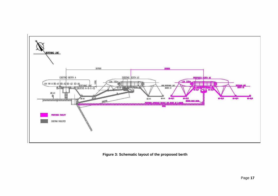
Berth will be designed to handle ships of LOA ranging from 105 to 228m. The berth
will handle 180 vessels in a year with average 15 vessels per month, similar to existing berths
which are currently in operation at existing jetty. A new Trestle on Piles will be constructed
from Knuckle Platform to the new Berth. The general layout and schematic layout of the
proposed berth is shown in Figure 2 & 3. The existing draft at the berth location is suitable for
safe berthing of required parcel size of ships.
The new Berth will be constructed with the facilities as described below.
4.1.1 Operating Platform
The deck level of Berths will be at +11.0 m CD with provision for installing 4 loading
arms on Berth. The Berth will consist of an operating platform made of concrete deck
supported on steel structures and steel piles. The operating platform shall be of 27 m x 21 m
size.

Page 6
Parameters of Berth are as follows
Table 1: Parameters of Proposed Berth
Parameters Berth
Parcel Size 3 – 50 KT
Vessel LOA (m) 105 – 228
Products HSD PCN PX Benzene MEG Acetic Acid
Pipelines Sizes 1 x 24” 1 x 24” 1 x 16” 1 x 12” 1 x 16” 1 x 12”
Loading Arms 1 x 12” 1 x 12” 1 x 10” 1 x 10”
Total Handling
Capacity
(MMTPA)
8 MMTPA
The Berth operating platform will be provided with the following facilities:
Oily water slops collection and disposal.
Field Instruments, cabling and junction boxes
Instrument and electrical cable trays, suitable for saline atmosphere (FRP)
Each product manifold shall have ESD valves on the Berth before connecting to
loading arms
Product recovery pumps will be provided for MEG, and Acetic Acid.
Sampling points
Separate dedicated MEG and acetic acid drain system
Utilities (Potable water, Fire water, Foam line, Slop line, Nitrogen supply for line
purging, Instrument air, Plant air)
Normal and Emergency lighting (includes Lighting Tower)
Earthing
Elevated Fire water / Foam Monitors etc.
Fire water loop as well as fire and gas detection system
Fire hose reel with Instantaneous Hose Coupling (IHC) connections in a box as per
code

Page 7
Life saving and safety equipment
Deluge valve activated sprinkler system
Firefighting equipment as per OISD 156 such as fire hydrants, potable fire monitor,
water barrier, fire hose reels with instantaneous coupling connections (IHC),
extinguishers etc.
Safety shower and eye wash fountain
Audio & visual indication for all general alarms
Manual Call Point (MCP) & Public Address System
Quick release hooks with local release by electric switch
Pedestal Crane – 5 MT capacity on Berth with reach over all the valves on
Berth platform to facilitate maintenance.
Porta cabin and adequate space for the movement of personnel and for carrying
out maintenance of above equipment / facilities (The porta cabin shall be equipped
with complete lighting, Public Address system etc.)
Emergency Escape route to sea (boat landing)
Cathodic protection
International fire water connection
Switch rack room near Berth to have power distribution board, motor starter, normal
+ emergency lighting distribution Board.
Switch rack room shall have F & G and FM 200 system for fire detection and
suppression.
Potable water tank of 1 Cu m capacity.
4.1.2 Breasting and Mooring Dolphins
a. Breasting Dolphins
Four Breasting Dolphins will be provided for ensuring safe berthing to cater berthing of
vessels of LOA range 105 m – 228 m. These shall be of steel structures on steel piles and
shall be provided with cone or Cell type fenders for absorbing the impact load while berthing
ships.

Page 8
Fenders will be designed to handle berthing forces of 65,000 DWT vessels. Breasting
dolphins shall be provided with Quick Release Hooks with Capstans, ladder access for boats
as required, Capstans and Safety Chains etc. and will be inter- connected with catwalks.
The Quick Release Hooks system on Breasting Dolphins shall be provided with local
release by electric switch on each Breasting Dolphin. A panel for operating the Breasting
Dolphins Quick Release Hooks shall be provided at each Switch Rack Room.
b. Mooring Dolphins
Five Mooring Dolphins will be provided for ensuring safe mooring of the vessels.
The dolphins shall be of steel structures on steel piles and shall be provided with Quick
Release Hooks with local release by electric or hydraulic switch, Mooring Rings, Chain
ladders, Capstans and Safety Chains etc. Mooring Hooks and Capstans will be designed and
provided to handle 50 KT parcel loaded vessels.
Mooring hook release system shall be provided with local release only with electro
hydraulic actuation. All mooring dolphins shall be connected with Catwalks for access and
ladder access to boats as required.
Mooring Dolphins will be connected to new trestle with catwalks as a secondary means
of escape.
All the piles required for Breasting dolphins, mooring dolphins, new pipe rack,
operating platform will be provided with cathodic protection.
4.1.3 New trestle From Knuckle Platform to Proposed Berth
From Knuckle platform to Berth, a new Trestle of approx. 650 m long will be built and
the trestle will be supported by piles. The trestle will carry all the product pipelines, utility
pipelines. Electrical and Instrument cables will be laid on cable tray provided on trestle. A
walkway will be provided along with the trestle.
New pipelines for HSD, MEG, Acetic Acid, PCN, Benzene and PX will be routed on
the new pipe trestle installed from knuckle platform to the Berth Platform. The firewater line
and utility lines for Berth will also be routed on the new pipe trestle.
A switch rack room shall be provided on the new trestle near the entrance to Berth
operating platform to accommodate electrical switchgear/distribution boards, marshaling
cabinets, F&G, DCS, ESD, Loading Arm PLCs, EV control system and other respective control
system.
Page 9
A fire monitor control panel shall be provided for berth on the trestle next to the switch
rack room to facilitate remote operation of fire water monitors. Adequate lighting facilities for
safe operations shall be provided.
Necessary structural modification at Knuckle platform will be carried out to
accommodate the above mentioned new facilities.
All the electrical and instrumentation and control cables will be routed on the cable tray
provided on the new pipe rack from knuckle platform to Berth Platform. From POC to knuckle
platform the cables will be routed on the existing cable tray supports with suitable modification
/ addition of supports.
A small boat landing facility, similar to existing berths, will be provided alongside of the
Berth platform.
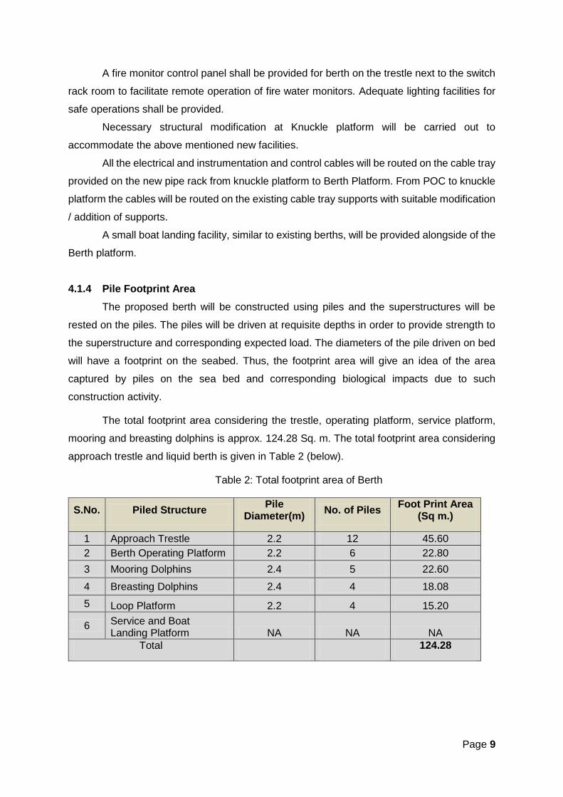
4.1.4 Pile Footprint Area
The proposed berth will be constructed using piles and the superstructures will be
rested on the piles. The piles will be driven at requisite depths in order to provide strength to
the superstructure and corresponding expected load. The diameters of the pile driven on bed
will have a footprint on the seabed. Thus, the footprint area will give an idea of the area
captured by piles on the sea bed and corresponding biological impacts due to such
construction activity.
The total footprint area considering the trestle, operating platform, service platform,
mooring and breasting dolphins is approx. 124.28 Sq. m. The total footprint area considering
approach trestle and liquid berth is given in Table 2 (below).
Table 2: Total footprint area of Berth
S.No. Piled Structure Pile
Diameter(m) No. of Piles
Foot Print Area (Sq m.)
1 Approach Trestle 2.2 12 45.60
2 Berth Operating Platform 2.2 6 22.80
3 Mooring Dolphins 2.4 5 22.60
4 Breasting Dolphins 2.4 4 18.08
5 Loop Platform 2.2 4 15.20
6 Service and Boat Landing Platform NA NA NA
Total 124.28

Page 10
4.1.5 Pipelines
Product Pipeline Route to Berth
Table 3: Product Pipeline Details and Route
Products Pipeline Sizes
MOC Connectivity
HSD 1 x 24” CS Tap-off from Existing Pipeline at Knuckle Platform to Berth
Benzene 1 x 12” CS Tap-off from Existing Pipeline at Knuckle Platform to Berth
MEG 1 x 16” SS 304 L New Pipeline from MTF B/L to Berth
Acetic Acid 1 x 12” SS 316 L New Pipeline from MTF B/L to Berth
PCN 1 x 24” CS Tap-off from Existing Pipeline at Knuckle Platform to Berth
PX 1 x 16” CS Tap-off from Existing Pipeline at Knuckle Platform to Berth
Apart from the product pipelines, the firewater, slop/oily water, foam line, potable water,
nitrogen, instrumentation and pipelines will be provided.
4.1.6 Loading Arms
Loading Arms on Berth
Berth will be provided with 1 number 12” CS loading arm for HSD & PCN, 1 number
12” CS loading arm for PX and Benzene & 2 numbers 10” SS loading arms - one each for
MEG and Acetic Acid.
A new PLC is envisaged at new switch rack room at Berth to control these new loading
arms.
For safe and easy transfer of products, loading arms will be provided on Berth. All
loading arms swivel joints will have split flange arrangement for packing replacement of swivel
joints. The greasing system will be centralized for swivel joints of loading arms.
Each loading arm will be provided with a Powered Emergency Release Coupler
(PERC). The hydraulic power pack and local control panel will be installed on the operating
platform. Cordless controls as well as pendant type controls shall be provided for operation of
the loading arms.
Isolation valves shall be provided at inlet and on return lines of hydraulic system of
each loading arm so that maintenance of individual loading arm can be done while others are
in operation.
Page 11
5. Vessel Berthing and Navigational Aids
The existing navigational channel will be used for navigation of vessels to proposed
berth. The depth in the existing channel and in proposed berthing area is sufficient for safe
navigation and berthing of 3 - 50 KT parcels size vessels. The existing lighted buoys and
markers along the channel will aid in safe navigation of vessels.
6. Pilotage
Pilotage shall be compulsory and vessels will be assisted by tugs for turning and
manoeuvring. Two tugs of 52 Tons bollard pull will be procured to assist operations at the
Berth. Additional mooring buoys for the new tugs will be provided at appropriate locations. All
the other required marine crafts such as mooring boats, speed boat for security etc. are
already available which are presently in use for operation of the existing marine terminal.
7. Health, Safety and Environment
As safety is the paramount aspect in the design of any marine terminal, no compromise
on safety shall be made. The highest standards are adopted in piping, routing, and selection
of hose pipes, controls, relays, operating systems, fire detection and fighting systems as
followed in existing installation.
Environmental, safety considerations and policies are an integral part of Reliance’s
Port & Terminal operations. From the inception stage, Berth will be fully designed to be safe
for both people working at the jetty and the marine environment on which the facilities are
proposed to be setup. Due care will be taken from the design phase of the projects so that the
spills will be minimal or negligible.
• Adequate number of life buoys shall be provided on the Berth platform.
• Safety shower and eye wash facility shall be located on the Berth.
• Gas detection systems to detect hydrocarbon leakage will be provided at Berths.
• All possibilities of oil / petrochemical spills on Berths during operations shall be
minimized. Any spills will be contained on the loading deck. Spillage of oily water
or petrochemicals to sea shall not be allowed.
• Berth will have provision for deployment of oil booms to contain any accidental
oil spills from Berths reaching the shore.
• Self-Contained Breathing Apparatus (SCBA) will be provided on berth for
emergency situation.
The terminal has a state of art infrastructure fully automated control rooms which are
engineered to have a safe working environment in accordance with local regulations and the

Page 12
company’s high level operating standards. Stringent safety procedures, applicable to both
companies and sub-contracted employees, will be practiced during the sites’ erection &
operations stages. Reliance has also made large investments in automation and installation
of advanced safety equipment and fire protection systems, which are maintained regularly.
Adequate and preventive measures are in place to control various emissions.
The terminal has an well-equipped Tier I Oil Spill Contingency Plan. The RIL port flotilla
like tugs and pollution control boats are equipped with various oil combating equipments like:
Oil absorbents pads and pillows, oil spill dispersants, Hi sprint boom, Air pack inflator, rotating
brush skimmers OSD spray booms etc. The terminal is equipped with two boats for security
surveillance and pollution prevention. The product jetty is equipped with permanent boom
along the jetty secured on top by wire ropes and below water level by sinkers covering an
length of about 1.1 km.
The jetty area is declared as “No waste disposal area”. All the vessels visiting the jetty
will have their own sewage treatment plant and will not be allowed to dispose any sort of waste
like bilge, chemicals, fuels, oils, greases, bituminous material, waste washing and concrete
drainage into the marine environment. Due to the proposed project, no significant solid /
hazardous waste will be generated.

Page 13
8. Operation and Maintenance
The existing Port Operation Center (P.O.C) shall control ship movements, berthing and
departure of ships. Utilities, fire-fighting and other operations shall also be controlled from the
P.O.C.
9. Power and Water Requirement
Reliance operates its own captive power plants and caters to the power requirements
all across the refinery complex as well as marine terminal. The water requirement for proposed
project will be met through the captive desalination facilities.
10. Site Analysis
10.1 Connectivity
By Road
The product jetty is connected to land through an approach trestle. The project is near
to the existing marine tank farm (MTF) within RIL complex. It is well connected with refinery
division through existing road passing through SH 92 and SH 6.
By Air
The nearest airport at Jamnagar is about 25 kms from the site.
By Sea Traffic
The convenient route of Gulf of Kutch and the demand for the new business
development in the export / import business encourage more transport of material at this
strategic location.
10.2 Land Form, Land Use and Land Ownership
The marine terminal is owned by RIL and falls within the limits of the Sikka Port of
GMB. The proposed berth will also fall within the port limits of GMB. The jetty limit has been
notified for commercial / industrial purpose, hence there is no change in the land use pattern
of the region.
10.3 Existing Infrastructure
Existing infrastructure at product jetty and MTF is well developed for the complex
namely POC, canteen, administration block, utility block, electrical substations, warehouse,
Page 14
store, workshop, tank farm, effluent treatment plant and raw and fire water storage reservoir
etc.
10.4 Climatic data of the region
Climate of the region is hot and humid. It is influenced by surrounding sea. The
maximum temperature during summer and minimum temperature during winter are reported
to be 47°C and 3°C respectively. Predominant wind directions vary from South and South-
West and North-East direction and annual average rainfall in the region is about 578 mm.
11. Project Schedule and Cost Estimate
11.1 Project Schedule
Start Date : Upon obtaining Environmental and CRZ Clearance
Completion Date : Two years from the date of grant of Environmental and CRZ
Clearance
11.2 Estimated project cost
The capex for the proposed Berth is approx. Rs. 750 crores
12. Conclusion
The proposed berth is required for handling additional product volumes expected from
manufacturing complex as well as to create risk redundancy at existing product jetty. Since
the proposed berth will be located at existing product jetty and will utilize the existing
infrastructure for its operation the likelihood of any significant impacts due to the same is not
envisaged. Although EIA studies will be performed for establishment of baseline and
evaluation of significant environment impacts if any.

Figure 1: Location of Proposed Berth

Figure 2: General layout of the proposed berth
Page 17
Figure 3: Schematic layout of the proposed berth