Power Measurement Basics - Stellenbosch...
45
Power Measurement Basics www.agilent.com/find/backtobas ics Power Measurement Basics
Transcript of Power Measurement Basics - Stellenbosch...

Power Measurement Basics www.agilent.com/find/backtobas
ics
Power Measurement Basics

Power Measurement Basics www.agilent.com/find/backtobas
ics
Agenda
l Importance and definitions of power measurements
l Average Power Measurementl Peak Power Measurementl Time Gated Power Measurementl Measurement uncertaintyl Considerations in choosing power
measurement equipmentl Appendices

Power Measurement Basics www.agilent.com/find/backtobas
ics
l Too low– Signal buried in noise
Importance of Proper Signal Levels
l Too high– Nonlinear distortion
can occur
– Or even worse!
RL 0.0 dBmATTEN 10 dB10 dB / DIV
START 150 MHz STOP 1.150 GHzRB 3.00 MHz VB 300 kHz ST 13.89 msec

Power Measurement Basics www.agilent.com/find/backtobas
ics
Why Not Measure Voltage?
l DC
l Low Frequency
l High Frequency
VInc
VRef
ZS
Z O
RL
VR
L
V RL
-
+
±
ZS
ZS
I
I

Power Measurement Basics www.agilent.com/find/backtobas
ics
Power: P = (I)(V)I
RV
+
-
Amplitude
t
P
I
V
DC component of powerAC component of power

Power Measurement Basics www.agilent.com/find/backtobas
ics
l Unit of power is the watt (W): 1W = 1 joule/sec
l Some electrical units are derived from the watt: 1 volt = 1 watt/ampere
l Relative power measurements are expressed in dB: P(dB) = 10 log(P/Pref)
l Absolute power measurements are expressed in dBm: P(dBm) = 10 log(P/1 mW)
Units and Definitions
Power: P = (I)(V)
Amplitude
t
P
I
V
DC component of power
AC component of power

Power Measurement Basics www.agilent.com/find/backtobas
ics
Types of Power Measurements
PeakPower Pulse Top
Amplitude Overshoot
Average Power
Duty CyclePulseDelay
PRI PRF
PulseWidth

Power Measurement Basics www.agilent.com/find/backtobas
ics
l Vector Signal Analyzerl Spectrum analyzerl Network analyzerl Power meter
Instruments used to Measure RF and Microwave Power

Power Measurement Basics www.agilent.com/find/backtobas
ics
Agenda
l Importance and definitions of power measurements
l Average Power Measurementl Peak Power Measurementl Time Gated Power Measurementl Measurement uncertaintyl Considerations in choosing power
measurement equipmentl Appendices

Power Measurement Basics www.agilent.com/find/backtobas
ics
Average Power
Average over several modulation cycles
timeAverage over many pulse repetitions
CW Signal

Power Measurement Basics www.agilent.com/find/backtobas
ics
Basic Measurement Method - Using a Power Meter
Substituted DC or low frequency equivalent
Net RF power absorbed by sensor
Power Sensor
PowerMeter Display
Diode DetectorsThermocouples
Thermistors

Power Measurement Basics www.agilent.com/find/backtobas
ics
Basic Measurement Method Explained
Diode SensorChopper
DiodeDetector
MeterSynchronousDetector LPF ADCRangingBPF
Square WaveGenerator
µProcessor
RF ACDC
220 Hz
DAC
AUTOZERO

Power Measurement Basics www.agilent.com/find/backtobas
ics
Power Ranges of the Various Sensor Types
-70 --60 -50 -40 -30 -20 -10 0 +10 +20 +30 +40 +50 [dBm]
Thermistors
Thermocouple square-law region
Extended range using an attenuator
Diode detector square-law region
Extended range using an attenuator
Wide Dynamic Range using Diode Detector for CW only or Modulated Signals

Power Measurement Basics www.agilent.com/find/backtobas
ics
Thermocouples
l The principles behind the thermocouple
Vh
Hot junction
Metal 1
Metal 2
- +V1
- +V2
Cold junction
-
+
1 2hV = V + V - V0
E-field
Bound Ions Diffused Electrons

Power Measurement Basics www.agilent.com/find/backtobas
ics
Thermocouples
l Thermocouple implementation
RF Input
Thin-FilmResistor
n - TypeSilicon
hot junction
hot
cold
cold junction
Thin-FilmResistor
To dc Voltmeter
Cc
C b
n - TypeSilicon
gold leads gold leads
RF power
Thermocouples

Power Measurement Basics www.agilent.com/find/backtobas
ics
Diode Detectors
l How does a diode detector work?
Vs CbRmatching
Rs
Vo
+
-

Power Measurement Basics www.agilent.com/find/backtobas
ics
Diode Detectors
Square Law Region of Diode Sensor
0.01 mW-70 dBm
VO (log)
Linear Region
[watts]0.1 nW
-20 dBm
Voµ PIN
P IN
Noise Floor
Vs CbRmatching
Rs
Vo
+
-

Power Measurement Basics www.agilent.com/find/backtobas
ics
Wide-Dynamic-Range CW-only Power Sensors

Power Measurement Basics www.agilent.com/find/backtobas
ics
E-series E9300 Power Sensors Technology
Innovative Design:
• Diode stack- attenuator-diode stack topology
• Two paths with an automatic switch point
Low Power Path
High Power Path
RF Input

Power Measurement Basics www.agilent.com/find/backtobas
ics
• Sensor diodes always kept in square law region.
• Accurate measurement of signals with high peak to average ratios.
• Accurate measurement of signals with arbitrarily wide modulation bandwidth.
• Flat calibration factors give accurate measurement of multi-tone signals.
Advantages of the E-series E9300 sensor architecture

Power Measurement Basics www.agilent.com/find/backtobas
ics
Agenda
l Importance and definitions of power measurements
l Average Power Measurementl Peak Power Measurementl Time Gated Power Measurementl Measurement uncertaintyl Considerations in choosing power
measurement equipmentl Appendices

Power Measurement Basics www.agilent.com/find/backtobas
ics
Peak Power MeasurementPeakPower
Average Power
Peak Power

Power Measurement Basics www.agilent.com/find/backtobas
ics
Sensor Diode Bulkhead
Thermistor-t°
3 dB
RF IN50ohm
Load Filter *(300 kHz, 1.5 MHz,5 MHz low pass)
GAIN SELECT
CHOP / CLOCK
CHOP / GAIN
SERIAL BUS
CW PATHISOLATE
NORMALPATH
Variable GainDifferential Amplifier *(300 kHz, 1.5 MHz, 5 MHz)
PEAK AUTO-ZERO
Thermistor BiasI2C BufferGain / Mode ControlSensor IDE2PROM
NORMALPATH
50 ohmload
Peak Power Measurement
AVERAGE ONLY PATHChopper
CW DifferentialAmp
SwitchedGainPreamp

Power Measurement Basics www.agilent.com/find/backtobas
ics
Agenda
l Importance and definitions of power measurements
l Average Power Measurementl Peak Power Measurementl Time Gated Power Measurementl Measurement uncertaintyl Considerations in choosing power
measurement equipmentl Appendices
Power Measurement Basics www.agilent.com/find/backtobas
ics
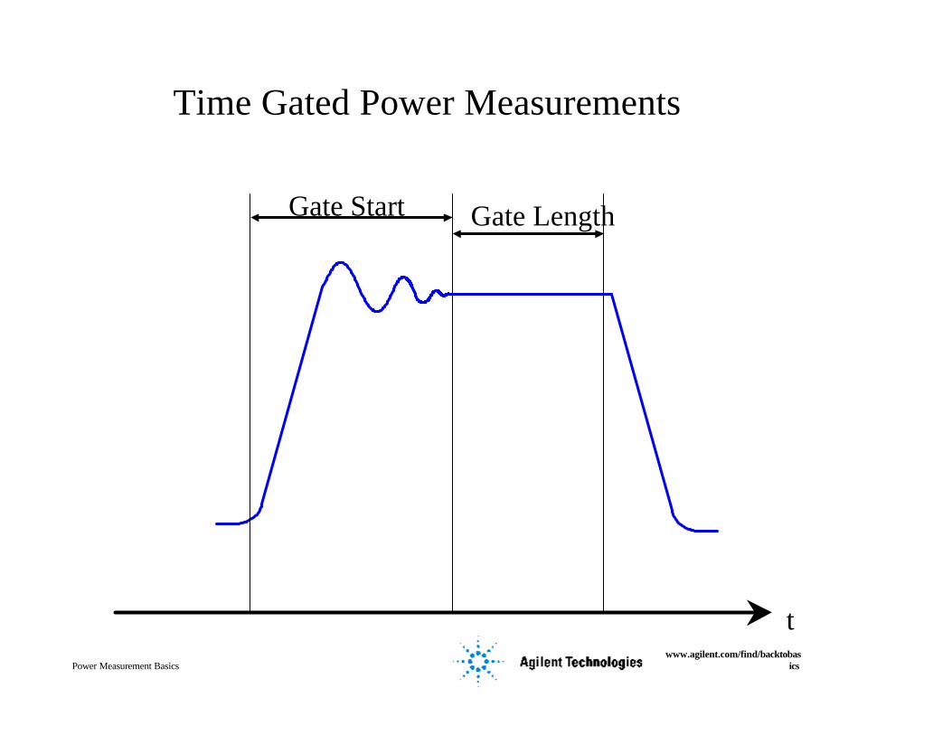
Time Gated Power Measurements
Gate Start Gate Length
t

Power Measurement Basics www.agilent.com/find/backtobas
ics
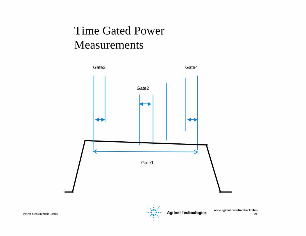
Time Gated Power Measurements
Gate4
Gate1
Gate2
Gate3
Power Measurement Basics www.agilent.com/find/backtobas
ics
Time Gated Power Measurements
Gate4
Gate1
Gate2
Gate3

Power Measurement Basics www.agilent.com/find/backtobas
ics
Sources of Power Measurement Uncertainty
l Sensor and source mismatch errorsl Power sensor errorsl Power meter errors
Mismatch
Sensor
Meter

Power Measurement Basics www.agilent.com/find/backtobas
ics
Calculation of Mismatch Uncertainty
Signal Source10 GHz
Power SensorPower Meter
Mismatch Uncertainty =±2 · 0.33 · 0.10 · 100% = ± 6.6%
Mismatch Uncertainty = ±2 · r · r · 100%SOURCE SENSOR
SOURCE
SWR = 2.0
SENSOR
SWR = 1.22r = 0.33 r = 0.10
Agilent E4412A Agilent E4418B

Power Measurement Basics www.agilent.com/find/backtobas
ics
Power Sensor Uncertainties(Effective Efficiency)
Various sensor losses
DC signal
PowerSensor
PowerMeter
Pr
ElementPi Pgl
Cal Factor: ηeKb= Pgl
Pi

Power Measurement Basics www.agilent.com/find/backtobas
ics
Power Meter Instrumentation UncertaintiesPower reference
uncertainty
Instrumentation uncertainty
+/- 1 count
Zero Set
Zero Carryover
Noise
Drift

Power Measurement Basics www.agilent.com/find/backtobas
ics
Calculating Power Measurement Uncertainty
Mismatch uncertainty:
Cal factor uncertainty:
Power reference uncertainty:
Instrumentation uncertainty:
Now that the uncertainties have been determined, how are they combined?
± 6.6%
± 3.1%
± 1.2%
± 0.5%
Power Measurement Basics www.agilent.com/find/backtobas
ics
Worst-Case Uncertainty
l In our example worst case uncertainty would be:
= 6.6% + 3.1% + 1.2% + 0.5% = ± 11.4%
+11.4% = 10 log (1 + 0.114) = + 0.47 dB
- 11.4% = 10 log (1 - 0.114) = - 0.53 dB

Power Measurement Basics www.agilent.com/find/backtobas
ics
RSS Uncertainty
l In our example RSS uncertainty would be:
= (6.6%) + (3.1%) + (1.2%) + (0.5%)
= ± 7.4%
+ 7.4% = 10 log (1 + 0.074) = +0.31 dB
- 7.4% = 10 log (1 - 0.074) = -0.33 dB
2 2 2 2

Power Measurement Basics www.agilent.com/find/backtobas
ics
Agenda
l Importance and definitions of power measurements
l Average Power Measurementl Peak Power Measurementl Time Gated Power Measurementl Measurement uncertaintyl Considerations in choosing power
measurement equipmentl Appendices

Power Measurement Basics www.agilent.com/find/backtobas
ics
Thermistors as Transfer Standards
NIST
NIST
Commercial Standards Laboratory
Manufacturing Facility
User
Rising Costs / Better Accuracy
Microcalorimeter
NationalReferenceStandard
Working Standards
MeasurementReference Standard
Transfer Standard
General TestEquipment

Power Measurement Basics www.agilent.com/find/backtobas
ics
SWR (Reflection Coefficient)

Power Measurement Basics www.agilent.com/find/backtobas
ics
Susceptibility to Overload
8478B Thermistor
Sensor
8481DDiode Sensor
8481A Thermocouple
Sensor
8481H Thermocouple
Sensor
Maximum Average Power
Maximum Energy per
Pulse
Peak Envelope Power
30 mW 300 mW 3.5 W 100 mW
10 W⋅µs 100 W⋅µs (1)
200 W 15 W 100 W 100 mW
E4412A Wide Dynamic Range
Diode Sensor
30 W⋅µs
200 mW
(1)
200 mW
(1) Diode device response is so fast, device cannot average out high-energy pulses
E9300A Wide Dynamic Range
Diode Sensor
315 mW
(1)
2W

Power Measurement Basics www.agilent.com/find/backtobas
ics
Agenda
l Appendix A -
Thermistor Mounts

Power Measurement Basics www.agilent.com/find/backtobas
ics
Thermistors
Characteristic curves of a typical thermistor element

Power Measurement Basics www.agilent.com/find/backtobas
ics
Thermistors
A self-balancing bridge containing a thermistor
RF Power
Thermistormount
R R
R
RT
-+
Bias

Power Measurement Basics www.agilent.com/find/backtobas
ics
Power Meters for Thermistor Mountsl 432A Power Meter
Thermistor mounts are located in the sensor, not the meter.

Power Measurement Basics www.agilent.com/find/backtobas
ics
Agenda
l Appendix B
Power Meter/Sensor Selection Guide

Power Measurement Basics www.agilent.com/find/backtobas
ics
100 kHz
10 MH
z
50 MH
z
2 GH
z
4.2 GH
z
6 GH
z
18 GH
z
26.5 GH
z
33 GH
z
40 GH
z
50 GH
z
75 GH
z
110 GH
z
Agilent Power Sensor Selection Guide -8480 Series
8481D
8481A
8481H
8481B
8485D
8482A
8482H
8482B
Q8486D
8483A (75 Ohm)
R8486D
8485A
8487D
W8486AV8486A
8487A
0 dBm to +44 dBm
-30 to +20 dBm
-70 to -20 dBm
-10 to +35 dBm
Q8486A
R8486A
Opt 033
Opt 033

Power Measurement Basics www.agilent.com/find/backtobas
ics
9 kHz
10 MH
z
50 MH
z
2 GH
z
4.2 GH
z
6 GH
z
18 GH
z
26.5 GH
z
33 GH
z
40 GH
z
50 GH
z
75 GH
z
110 GH
zAgilent Power Sensor Selection GuideE-Series Wide Dynamic Range Sensors
E9301A
E9300A
E4412A
E4413A
E9300H
E9300B
E9301H
E9301B-30 to +44 dBm
-60 to +20 dBm
-70 to +20 dBm
-50 to +30 dBm
E9304A
CW Only
H18