Power management in embedded multi-core architectures · Power management in embedded multi-core...
17
Power management in embedded multi-core architectures Karim Ben Chehida , Raphaël David [email protected] CEA LIST, Saclay
-
Upload
truongkien -
Category
Documents
-
view
223 -
download
0
Transcript of Power management in embedded multi-core architectures · Power management in embedded multi-core...

Power management in embedded multi-core architectures
Karim Ben Chehida, Raphaël David [email protected]
CEA LIST, Saclay

Outline
• Application and architectural trends
• The SCMP architecture
• Former LIST’s power management solutions
• New challenges
" 2

Embedded Applications trends
• Embedded systems must support various applications • They need more computing power
1 GOPS
0.1
10
100
1 TOPS
HD Audio
Multimedia
OpenGL1.1
OpenGL 2.0
H264
Digital TV
Mobile multimedia
MPEG2
3D Graphics
UMTS
EDGE
GPRS
GSM
WIMAX
3GPP-LTE
SDR
Telecom
DVB-S2
" 3
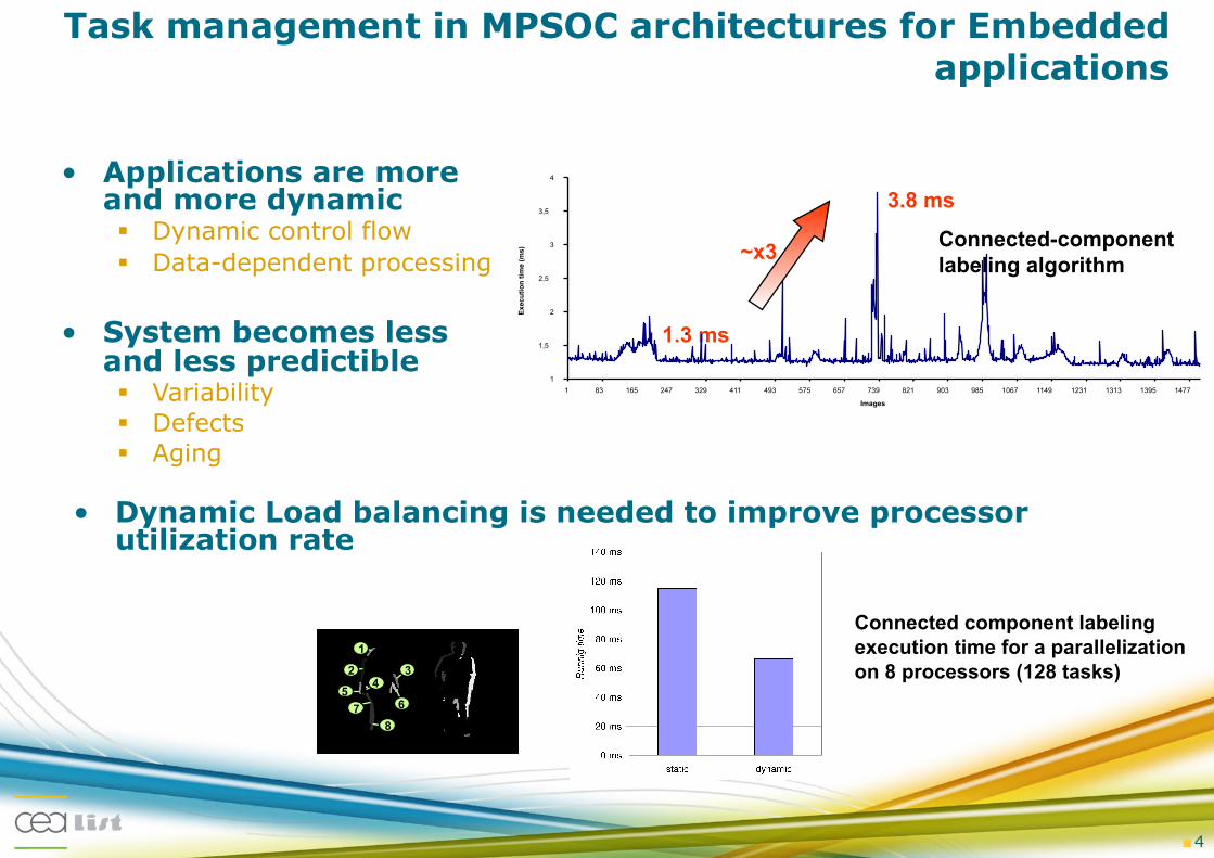
Task management in MPSOC architectures for Embedded applications
• Applications are more and more dynamic Dynamic control flow Data-dependent processing
• System becomes less and less predictible Variability Defects Aging
• Dynamic Load balancing is needed to improve processor utilization rate
Connected-component labeling algorithm
3.8 ms
1.3 ms
~x3
1 1,5
2 2,5
3 3,5
4
1 83 165 247 329 411 493 575 657 739 821 903 985 1067 1149 1231 1313 1395 1477 Images
Exec
utio
n tim
e (m
s)
Connected component labeling execution time for a parallelization on 8 processors (128 tasks)
8
2
1
5 4
7
3
6
" 4

" 5
• Software management of tasks is however not for free Low reactivity Low transistor and silicon efficiency Overhead hardly predictable
because of its dependencies regarding workload
• Benefits of hardware acceleration Overlapping between control and
computation activities Determinism Reactivity Low cost
Task management implementation issues
The Scheduler and the time tick processing overheads in MicroC/OS-II on a PowerPC, A Configurable Scheduler for Real-Time Systems – ERSA03
Tâche Tâche Tâche
System interface
Processeur
API
Task
Application
Interrupt/ signaling
HMI
Tâche Tâche Tâche task
Application
Processeur Processeur Procesors
Allocation and scheduling
Synchronizations
Memory Mgnt
File mgnt
System messaging
Task mgnt Time Mgnt
IO mgnt Internal com mgnt
Resources sharing
HAL
NoC
Memory
PE
Memory
PE Control
Memory
OS (Host
processor)
Computing
HW-RTOS

Hardware support for task management
• Full Hardware solution For asymmetric approaches
May need several 100kgate but support very aggressive real time scheduling approaches
• HW accelerated SW solution For SMP systems
Less than 100kgate Not so smart but allows secured
sharing of system information and centralized signalization schemes
• Mixed approach For multi-purpose asymmetric approaches Based on a small RISC processor with optimized coprocessor interface
PE and Memory
Allocation Selection
Control Interface / CPL (CI)
Task Exec. and
Synch.
CPU Mgnt
Scheduling PE Ctrl
Fault-tolerance Mgr
L1
Interconnect
Core
L1
Core
L1
Memory Interface
On/O
ff control
Cluster monitors
Core
Cluster monitors
Event/ Interrupt Manager
It Mgr C/S Regs
Fault-Tolerance C/S Registers
Power Mgt
Internal Registers
Prog. Notifier C/S Registers
Programmable Notifier
Synchronization C/S Registers
Synchro Regs Updater
Power C/S regs
Mem
ory
(L2,
L3, E
xter
n)
" 6

SCMP: a new architecture for dynamic applications
• New execution and programming model Simplify the task parallelism management Optimize the PE occupancy (load balancing) Asymmetric architecture with a global control Fast preemption and migration of tasks Explicit separated execution between control and computation
Low control overhead (HW accelerator)
Specific memory management Physically distributed and logically shared Write exclusive accesses Data and instruction virtualization
CPU Operating System (real-time)
SCMP
System Bus
Interconnection Resource
PE mem instr mem data
PE mem instr mem data
mem
controller I/O
I/O
mem mem mem
PE mem instr mem data
mem mem mem instr instr instr instr instr
Memory Configu-ration and Manage-ment Unit
GA GA GA GA
controller I/O
GA
I/O
OSoC : HW Controller
" 7

Power Management strategies in SCMP
• Use all hardware support Idle modes Variable Voltage/frequency
• Adapt power management strategies to application needs Real Time Best effort in dataflow applications
Choice of the ideal low power mode TIDLE
si
di
ai
Time
Power
PSMi
Sleep Wake up
Choice of the ideal slow down factor TIDLE
di
ai
Time
Power
IDLE
Speed up Slow down
ai : arrival time
si : WCET
di : deadline
si
di
ai
Time
Power
IDLE
" 8

– Low Power State Parameters :
• PS = State Power Consumption.
• ETR = Transition energy consumption
• TTR = Transition latency
• TBE = Break-Event Time: minimum time to spend in state S so that the transition become interesting.
PXA270 PSM
Time
Power
IDLE
What is the Idle period on processor P (predict the future !!!)
What is the ideal low power mode S corresponding to the predicted idle time ???
S
Sleep Wake up
The DPM techniques – Generalities
" 9
Idle mode management

Idle mode management
• In real Time Systems Characterize offline (using WCET) the variation of the
parallelism rate of each application Detect online these variations and deduce the Idle periods Activate the ideal low power mode (modified LEA) and predict
the corresponding awakening time
• In dataflow mode Switch to idle mode as soon as data buffer reaches a critically
low filling rate threshold Awake whenever data buffer has been filled enough
" 10

Voltage and frequency scaling
• In real time applications Take benefits of slack times
Limit the amount of Voltage/frequency modification Accumulate slacks until being able to activate DVFS for a long period of time
Assign the slack to the next task on the same processor (% resource dependency) to avoid wasting slack time when reaching joining points in applications
• In dataflow applications Adapt production and consumption rates to avoid stalls when pipeline is
unbalanced
EDVFS = 4,5 x 925mW + 6,5 x 116mW = 4,916J
-52% Joules
D1 D2 D0 T2 T1 T0
t(s)
925 116
0 0 1 2 3 4 5 6 7 8 9 10 11 12 13 14
Eth = 11 x 925mW = 10,175J T1 T2 T0 D1 D2 D0
925 0 t(s) 0 1 2 3 4 5 6 7 8 9 10 11 12 13 14
T1 T2 T0 D1 D2 D0
925 0 t(s) 0 1 2 3 4 5 6 7 8 9 10 11 12 13 14
Excess
" 11

SCMP proptotype
• Complete FPGA prototype 75 MHz prototypes on FCM4 boards from Scaleo Chip (StratixIII based) Including OSoC and additionnal power management accelerators
For real time DPM and DVFS management
4 Processing Elements Based on sparc processors With Data Prefetch Engines + standard cache memories
Multibanked memory system With HW support for dynamic allocation
A H B
PE0 PE1 PE2 PE3
Selection $D $D $D $D
$D $D
RAM DPS TLB
DPS TLB
DPS TLB
DPS TLB
GPTimer UART Debug
Host
M U L T I - B U S
$I
$I
$I
$I ITMP
UGM 0 ms
10 ms 20 ms 30 ms 40 ms 50 ms 60 ms 70 ms
1 2 4 8
Run
ning
tim
e
PE number
scheduling wait for data running labelling
" 12

Outline
• Application and architectural trends
• The SCMP architecture
• Former LIST’s power management solutions
• New challenges
" 13
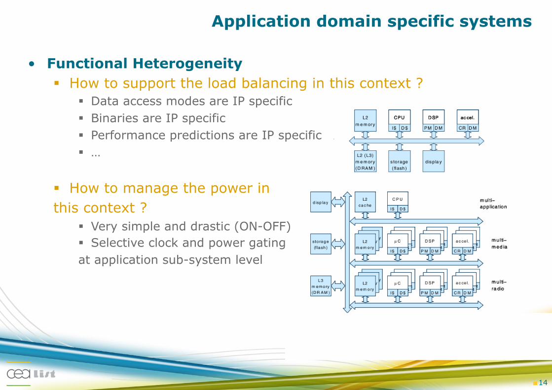
Application domain specific systems
• Functional Heterogeneity How to support the load balancing in this context ?
Data access modes are IP specific Binaries are IP specific Performance predictions are IP specific …
How to manage the power in this context ?
Very simple and drastic (ON-OFF) Selective clock and power gating at application sub-system level
" 14

• A many-core fabric Homogeneous or Heterogeneous resources Not clustered by application
• The fabric dynamic management allows to support: Faults (remanant or transient, aging…) Complex applications not fully predictable at compile time
Load balancing Power Management
• Possible approaches for complexity management
Globally static locally dynamic management:
Dynamic application deployment, no migration between clusters
Globally dynamic management Dynamic application deployment, possible inter-cluster migration Or Dynamic task deployment (at task creation)
" 15
From multi- to many-cores
Core Core Core Core
L1 L1 L1 L1
L2
Core Core Core Core
L1 L1 L1 L1
Synchronizer
XFC NI
Core Core Core Core
L1 L1 L1 L1
L2
Core Core Core Core
L1 L1 L1 L1
Synchronizer
XFC NI
Core Core Core Core
L1 L1 L1 L1
L2
Core Core Core Core
L1 L1 L1 L1
Synchronizer
XFC NI
Core Core Core Core
L1 L1 L1 L1
L2
Core Core Core Core
L1 L1 L1 L1
Synchronizer
XFC NI
Core Core Core Core
L1 L1 L1 L1
L2
Core Core Core Core
L1 L1 L1 L1
Synchronizer
XFC NI
Core Core Core Core
L1 L1 L1 L1
L2
Core Core Core Core
L1 L1 L1 L1
Synchronizer
XFC NI
Core Core Core Core
L1 L1 L1 L1
L2
Core Core Core Core
L1 L1 L1 L1
Synchronizer
XFC NI
Core Core Core Core
L1 L1 L1 L1
L2
Core Core Core Core
L1 L1 L1 L1
Synchronizer
XFC NI
Core Core Core Core
L1 L1 L1 L1
L2
Core Core Core Core
L1 L1 L1 L1
Synchronizer
XFC NI
Core Core Core Core
L1 L1 L1 L1
L2
Core Core Core Core
L1 L1 L1 L1
Synchronizer
XFC NI
Core Core Core Core
L1 L1 L1 L1
L2
Core Core Core Core
L1 L1 L1 L1
Synchronizer
XFC NI
Core Core Core Core
L1 L1 L1 L1
L2
Core Core Core Core
L1 L1 L1 L1
Synchronizer
XFC NI
Core Core Core Core
L1 L1 L1 L1
L2
Core Core Core Core
L1 L1 L1 L1
Synchronizer
XFC NI
Core Core Core Core
L1 L1 L1 L1
L2
Core Core Core Core
L1 L1 L1 L1
Synchronizer
XFC NI
Core Core Core Core
L1 L1 L1 L1
L2
Core Core Core Core
L1 L1 L1 L1
Synchronizer
XFC NI
Core Core Core Core
L1 L1 L1 L1
L2
Core Core Core Core
L1 L1 L1 L1
Synchronizer
XFC NI
Core Core Core Core
L1 L1 L1 L1
L2
Core Core Core Core
L1 L1 L1 L1
Synchronizer
XFC NI
Core Core Core Core
L1 L1 L1 L1
L2
Core Core Core Core
L1 L1 L1 L1
Synchronizer
XFC NI
Core Core Core Core
L1 L1 L1 L1
L2
Core Core Core Core
L1 L1 L1 L1
Synchronizer
XFC NI
Core Core Core Core
L1 L1 L1 L1
L2
Core Core Core Core
L1 L1 L1 L1
Synchronizer
XFC NI

• Advanced process variability From a design based on the worst case to a design based on the average case
with online adaptation For each processor, the frequency is evaluated and corrected online
Implies a GALS functioning model DVFS modes support tends to be generalized in complex systems Need a low footprint HW support for voltage and frequency adaptation (from DC-DC
VDD Hoping)
High performance heterogeneity Need to reconsider performance homogeneity hypothesis in the large scheduling
literature Tighter coupling of Power management policies with the allocation phase:
With the Load balancing policies With the system monitoring with the thermal management policies
• Effect of the temperature on the static power consumption overall power consumption
• Effect of the (frequency, voltage) operating point on the temperature
" 16
From multi- to many-cores

• The transition from multi-core to many core systems is not straightforward as far as the dynamic system management is concerned : HW acceleration of control primitives can lead to high controllability
At the lower hierarchy level for witch it can be well dimensioned
• Power management policies targeting many-core systems must take into account the process variability Reactive and proactive policies can be considered
• Many core system dynamic power management is more tightly coupled to the Task allocation phase With or without Load balancing techniques
• The effect of temperature on the power consumption and vice versa is not well estimated for 32nm and beyond … Benefits of coupling the Thermal and power management techniques…
" 17
Conclusion