Power-Gen Europe 2005 for Grid Connection - ABB Group-+ID197_200+-+ABB+Presentation+FACTS… ·...
30
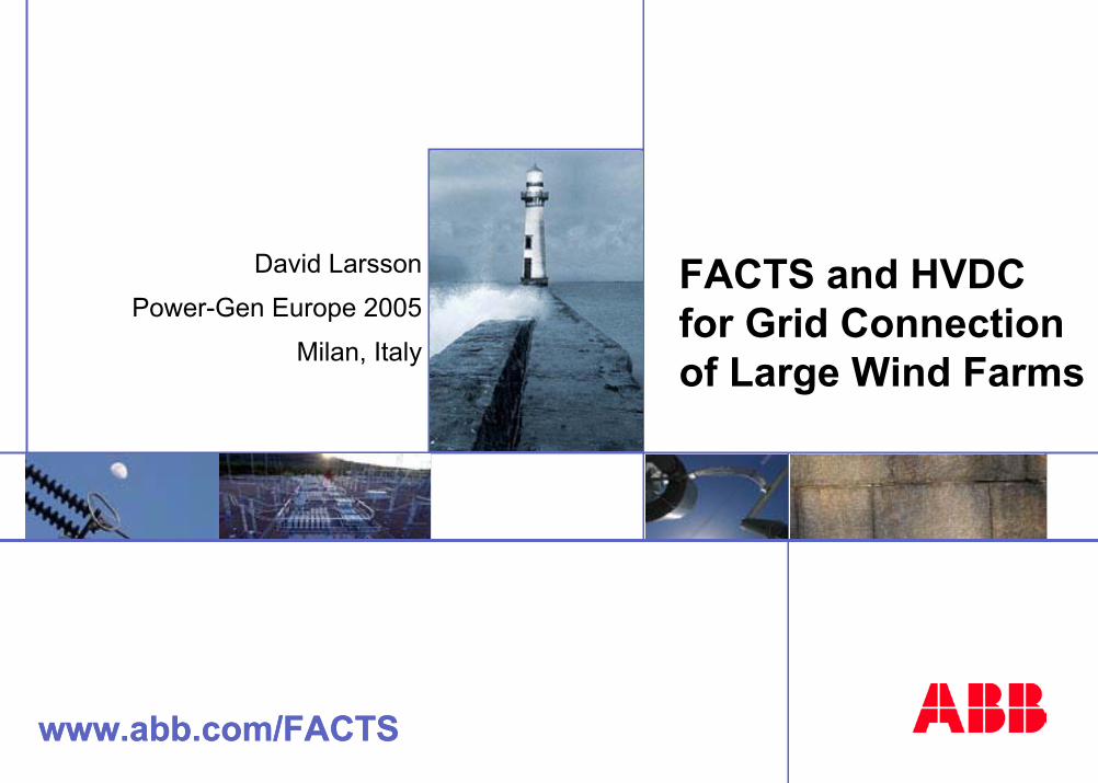
www.abb.com/FACTS FACTS and HVDC for Grid Connection of Large Wind Farms www.abb.com/FACTS David Larsson Power-Gen Europe 2005 Milan, Italy
Transcript of Power-Gen Europe 2005 for Grid Connection - ABB Group-+ID197_200+-+ABB+Presentation+FACTS… ·...
www.abb.com/FACTS
FACTS and HVDC for Grid Connection of Large Wind Farms
www.abb.com/FACTS
David Larsson
Power-Gen Europe 2005
Milan, Italy
©AB
B D
ate
25-N
ov-0
4-2
-FACTS
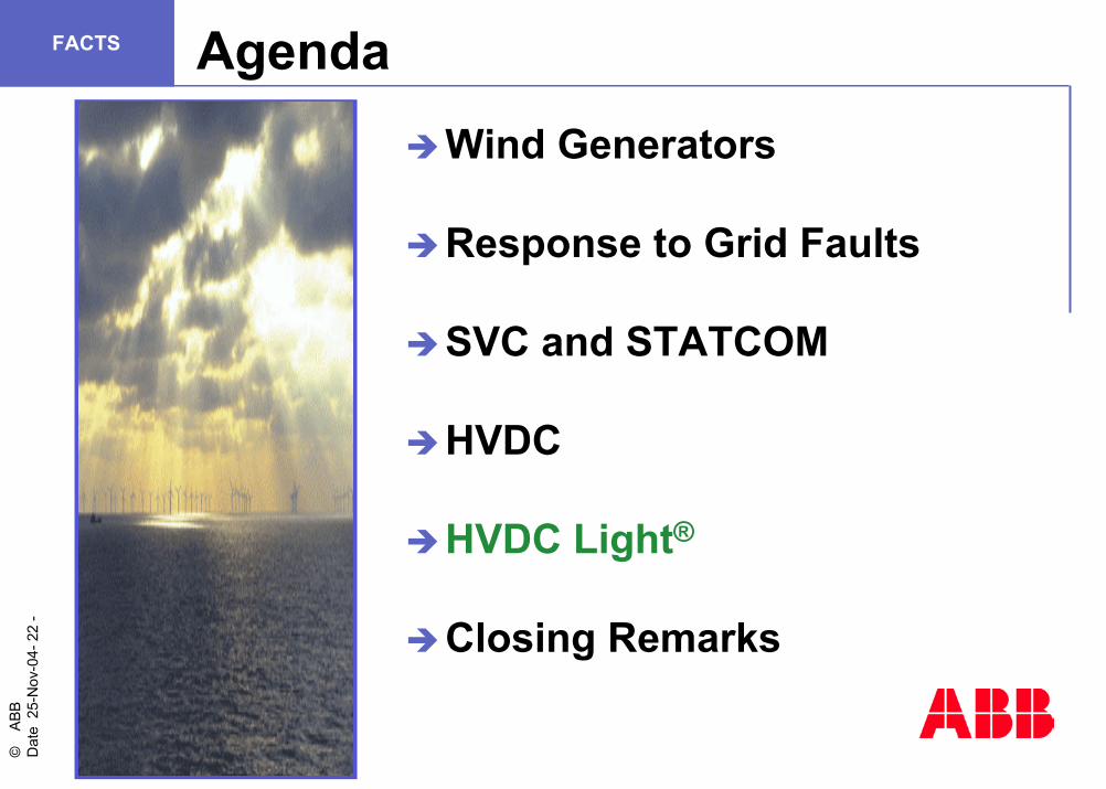
Wind Generators
Response to Grid Faults
SVC and STATCOM
HVDC
HVDC Light®
Closing Remarks
Agenda
PICTUREJPG-FORMAT
WEB OPTIMIZED RESOLUTION
©AB
B D
ate
25-N
ov-0
4-3
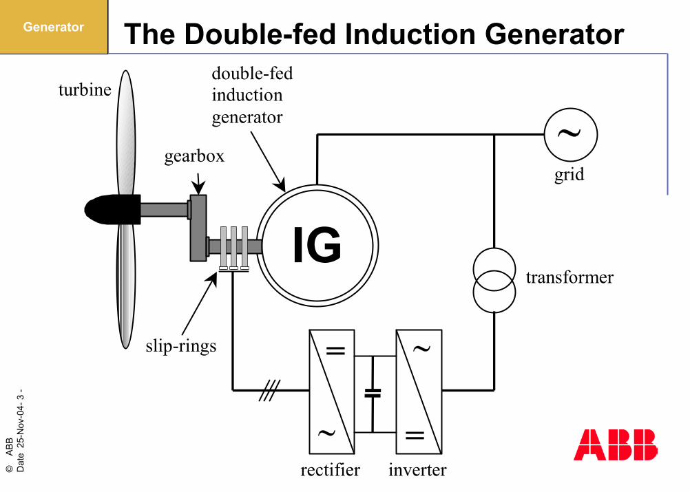
-FACTS The Double-fed Induction Generator
IG
=
∼ =
∼
∼turbine
gearbox
double-fedinductiongenerator
slip-rings
rectifier inverter
transformer
grid
Generator

©AB
B D
ate
25-N
ov-0
4-4
-FACTS Equivalent Circuits (for Positive-sequence)
i s rS xS xR
xm
rR /sShort-
circuitedinductiongenerator
uS
i s rS xS xR
xm
rR /sDoubly-
fedinductiongenerator
uR /s
uS
Generator
©AB
B D
ate
25-N
ov-0
4-5
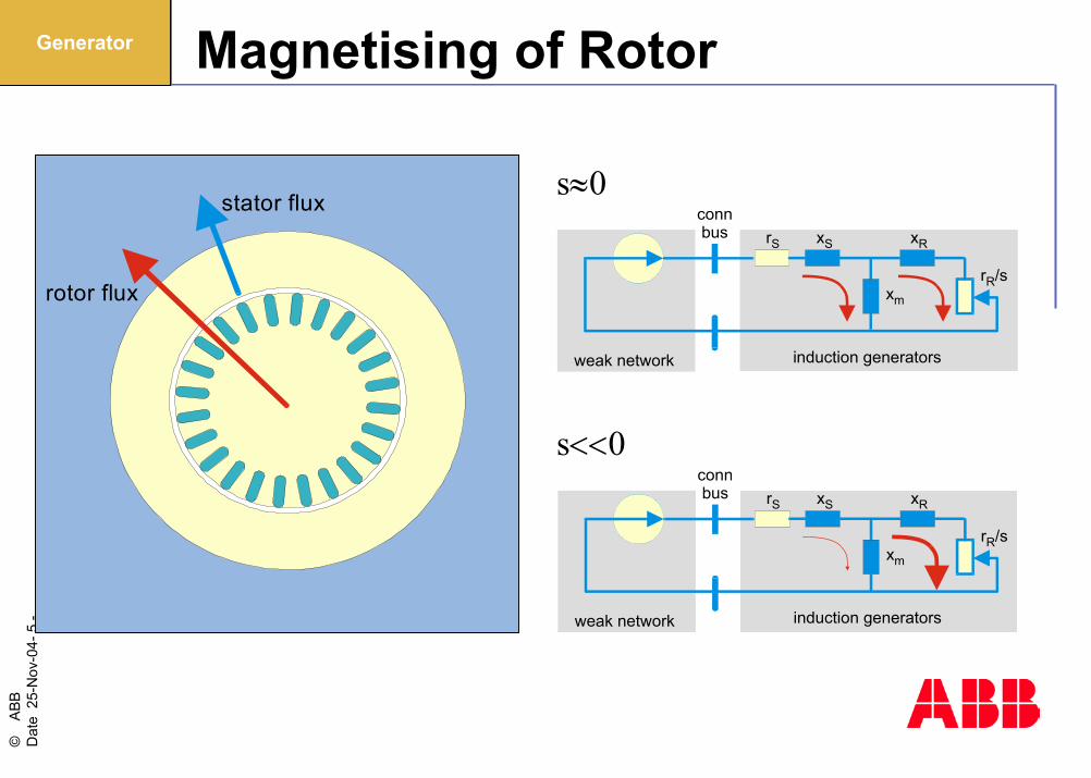
-FACTS Magnetising of Rotor
stator flux
rotor flux
weak network
connbus
induction generators
rS xS xR
xm
rR/s
weak network
connbus
induction generators
rS xS xR
xm
rR/s
s≈0
s<<0
Generator
©AB
B D
ate
25-N
ov-0
4-6
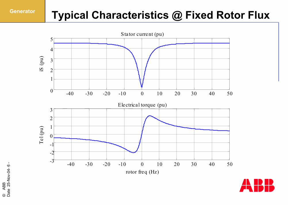
-FACTS Typical Characteristics @ Fixed Rotor Flux
-40 -30 -20 -10 0 10 20 30 40 500
12
3
4
5iS
(pu)
S ta tor current (pu)
-40 -30 -20 -10 0 10 20 30 40 50-3-2-10
123
rotor freq (Hz)
Tel (
pu)
Electrical torque (pu)
Generator
©AB
B D
ate
25-N
ov-0
4-7
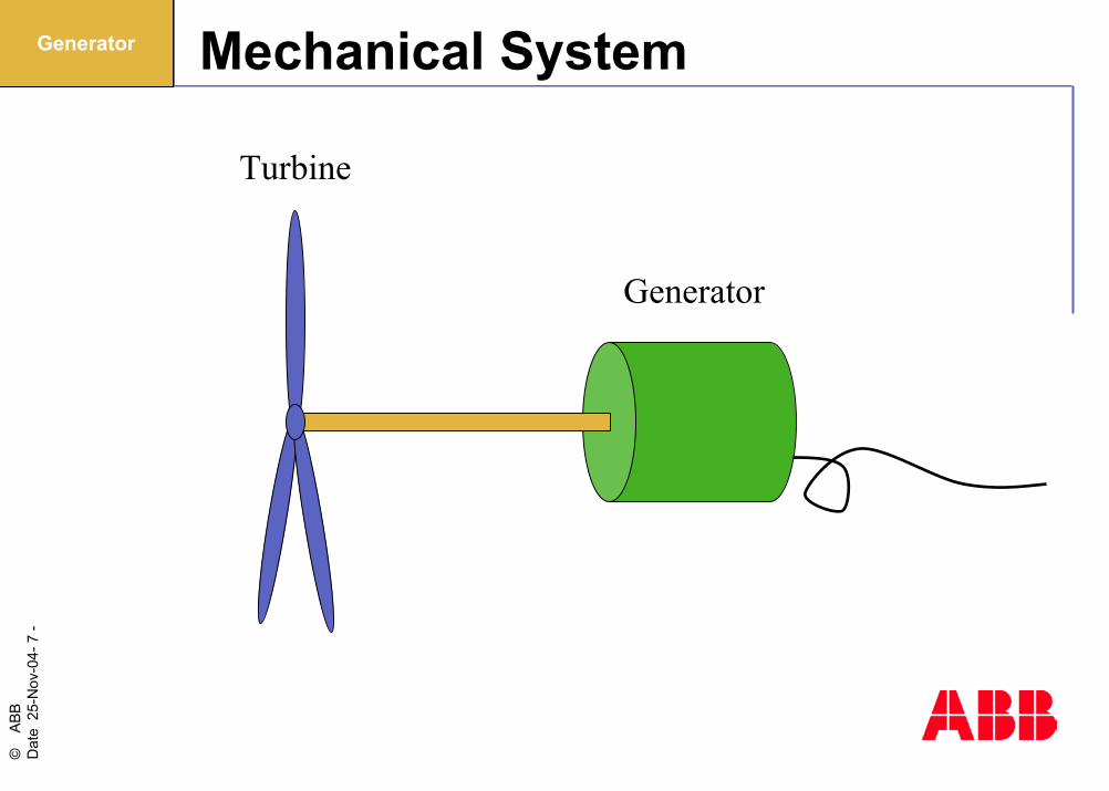
-FACTS Mechanical System
Turbine
Generator
Generator

©AB
B D
ate
25-N
ov-0
4-8
-FACTS
Wind Generators
Response to Grid Faults
SVC and STATCOM
HVDC
HVDC Light®
Closing Remarks
Agenda
PICTUREJPG-FORMAT
WEB OPTIMIZED RESOLUTION
©AB
B D
ate
25-N
ov-0
4-9
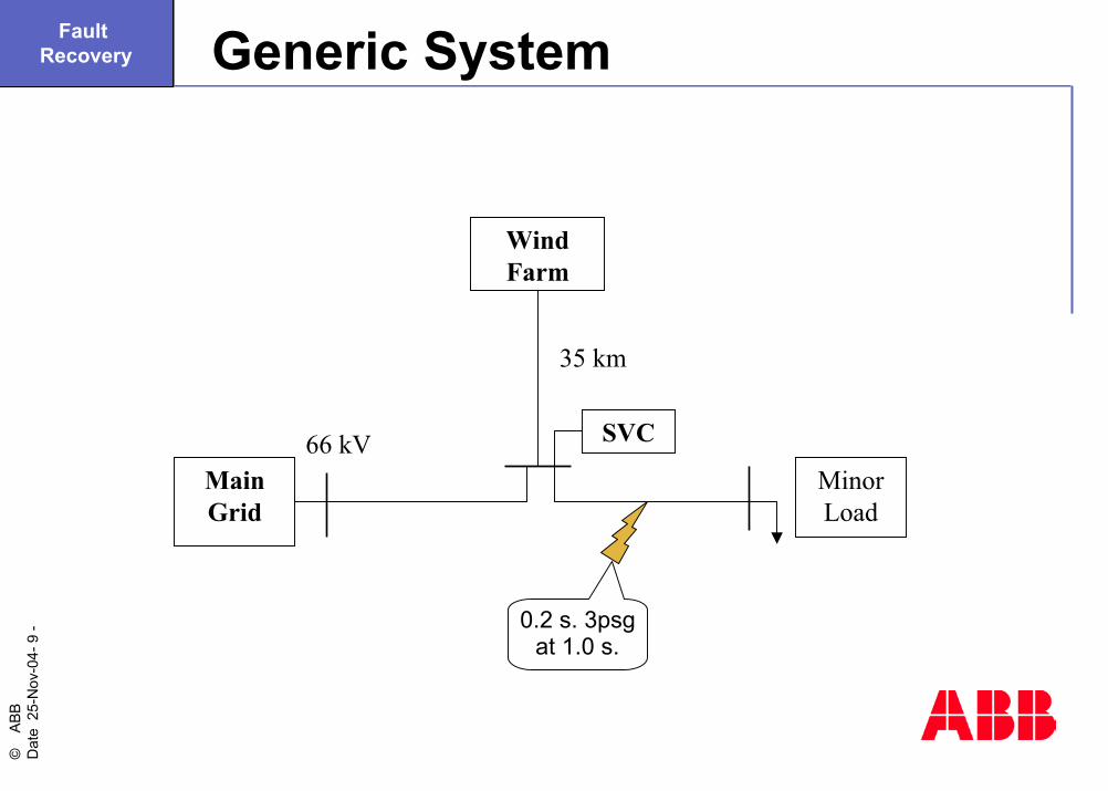
-FACTS Generic System
MinorLoad
MainGrid
WindFarm
35 km
66 kV SVC
0.2 s. 3psgat 1.0 s.
Fault Recovery
©AB
B D
ate
25-N
ov-0
4-10
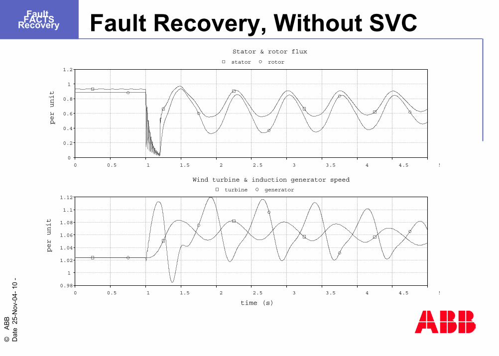
-FACTS Fault Recovery, Without SVC
0
0.2
0.4
0.6
0.8
1
1.2
per unit
0 0.5 1 1.5 2 2.5 3 3.5 4 4.5 5
stator rotor
0.98
1
1.02
1.04
1.06
1.08
1.1
1.12
per unit
0 0.5 1 1.5 2 2.5 3 3.5 4 4.5 5
time (s)
turbine generator
Stator & rotor flux
Wind turbine & induction generator speed
Fault Recovery
©AB
B D
ate
25-N
ov-0
4-11
-FACTS
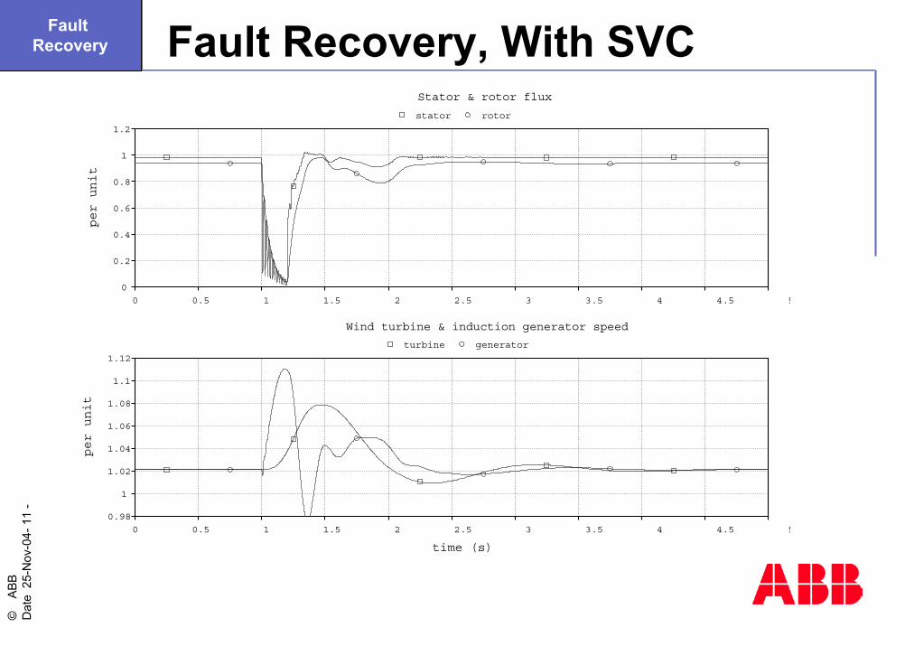
0
0.2
0.4
0.6
0.8
1
1.2
per unit
0 0.5 1 1.5 2 2.5 3 3.5 4 4.5 5
stator rotor
0.98
1
1.02
1.04
1.06
1.08
1.1
1.12
per unit
0 0.5 1 1.5 2 2.5 3 3.5 4 4.5 5
time (s)
turbine generator
Stator & rotor flux
Wind turbine & induction generator speed
Fault Recovery, With SVCFault Recovery
©AB
B D
ate
25-N
ov-0
4-12
-FACTS
Wind Generators
Response to Grid Faults
SVC and STATCOM
HVDC
HVDC Light®
Closing Remarks
Agenda
PICTUREJPG-FORMAT
WEB OPTIMIZED RESOLUTION

©AB
B D
ate
25-N
ov-0
4-13
-FACTS Combined VSC and TSC Scheme
132 kV
150 MVA
VSC+/- 53 Mvar
TSC94 Mvar
FC3 Mvar
~=
SVC & STATCOM
©AB
B D
ate
25-N
ov-0
4-14
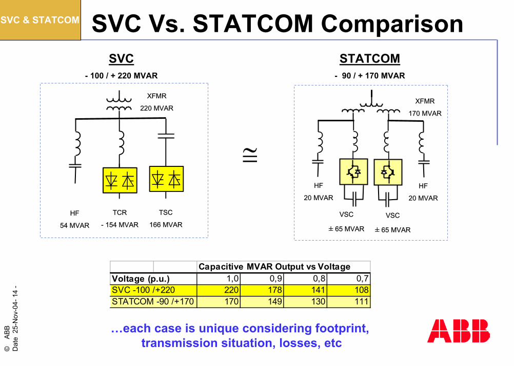
-FACTS SVC Vs. STATCOM Comparison
Capacitive MVAR Output vs VoltageVoltage (p.u.) 1,0 0,9 0,8 0,7SVC -100 /+220 220 178 141 108STATCOM -90 /+170 170 149 130 111
HF
54 MVAR
TCR
- 154 MVAR
TSC
166 MVAR
XFMR
220 MVAR
SVC- 100 / + 220 MVAR
STATCOM- 90 / + 170 MVAR
HF
20 MVAR
XFMR
170 MVAR
VSC
± 65 MVAR
VSC
± 65 MVAR
HF
20 MVAR
≅
…each case is unique considering footprint, transmission situation, losses, etc
SVC & STATCOM
©AB
B D
ate
25-N
ov-0
4-15
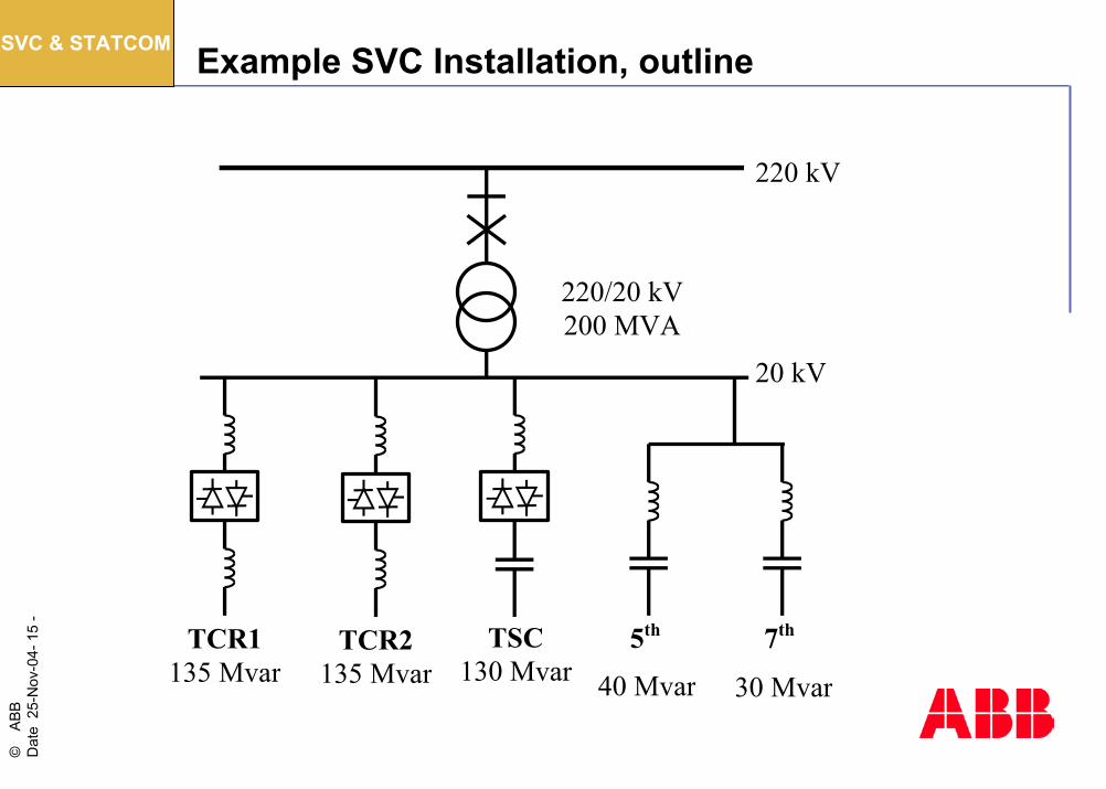
-FACTS Example SVC Installation, outline
TCR1 135 Mvar
TSC 130 Mvar
5th 7th
40 Mvar
220/20 kV 200 MVA
30 Mvar
20 kV
220 kV
TCR2 135 Mvar
SVC & STATCOM
©AB
B D
ate
25-N
ov-0
4-16
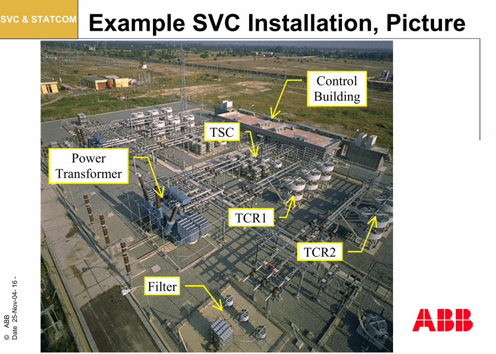
-FACTS Example SVC Installation, Picture
Control Building
TCR2
TCR1
Filter
TSC
Power Transformer
SVC & STATCOM
©AB
B D
ate
25-N
ov-0
4-17
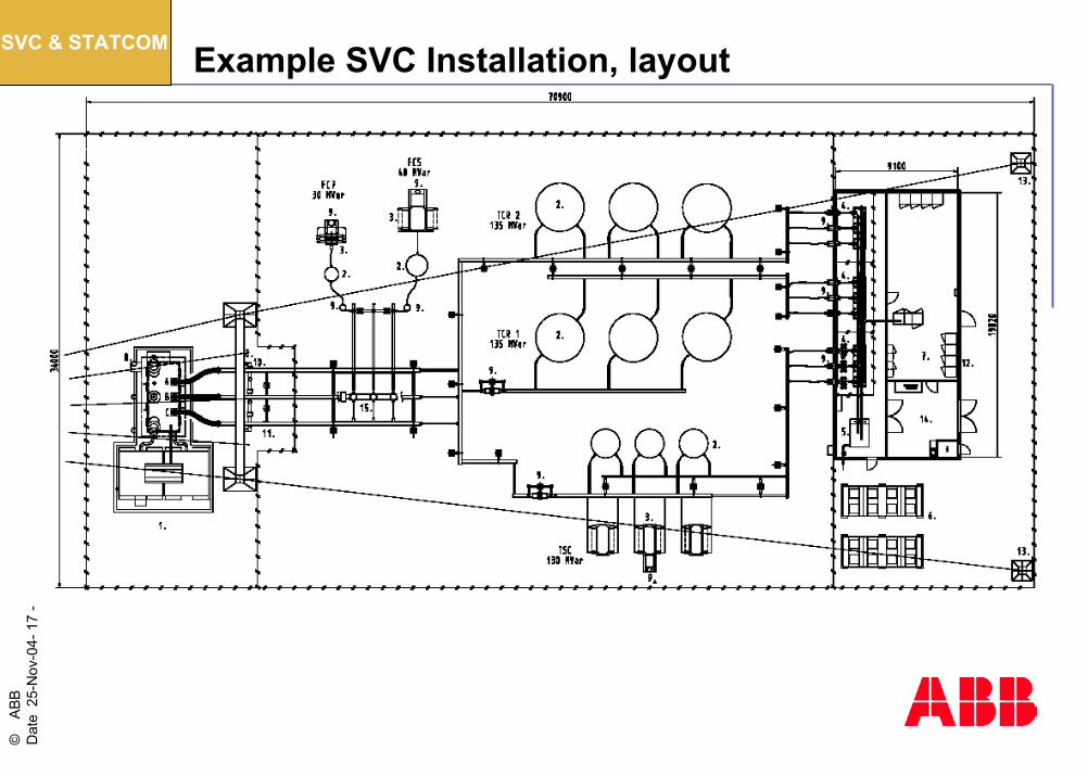
-FACTS Example SVC Installation, layoutSVC & STATCOM
©AB
B D
ate
25-N
ov-0
4-18
-FACTS
Wind Generators
Response to Grid Faults
SVC and STATCOM
HVDC
HVDC Light®
Closing Remarks
Agenda
PICTUREJPG-FORMAT
WEB OPTIMIZED RESOLUTION

©AB
B D
ate
25-N
ov-0
4-19
-FACTS Why HVDC? Part 1
One reason for choosing a High Voltage Direct Current (HVDC) trans-mission system for the connection of an offshore wind farm might be a long distance between the wind farm and the grid connection point, where HVAC cables can not be used due to their charging current.
HVDC
©AB
B D
ate
25-N
ov-0
4-20
-FACTS Why HVDC? Part 2
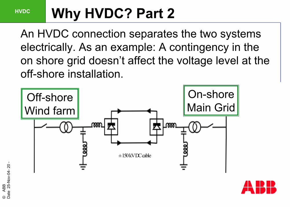
An HVDC connection separates the two systems electrically. As an example: A contingency in the on shore grid doesn’t affect the voltage level at the off-shore installation.
± 150kV DC cable± 150kV DC cable
Off-shoreWind farm
On-shoreMain Grid
HVDC
©AB
B D
ate
25-N
ov-0
4-21
-FACTS Why HVDC? Part 3
• It is possible to operate of the wind farm at different and/or varying frequency, e.g. for optimum use of the wind energy.
• Assuming VSC technology, both the off-shore installation and the on-shore grid can be supported with dynamic reactive power.
• Lower resistive losses in the interconnecting cable.
HVDC
©AB
B D
ate
25-N
ov-0
4-22
-FACTS
Wind Generators
Response to Grid Faults
SVC and STATCOM
HVDC
HVDC Light®
Closing Remarks
Agenda
PICTUREJPG-FORMAT
WEB OPTIMIZED RESOLUTION
©AB
B D
ate
25-N
ov-0
4-23
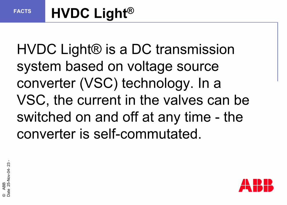
-FACTS HVDC Light®
HVDC Light® is a DC transmission system based on voltage source converter (VSC) technology. In a VSC, the current in the valves can be switched on and off at any time - the converter is self-commutated.
©AB
B D
ate
25-N
ov-0
4-24
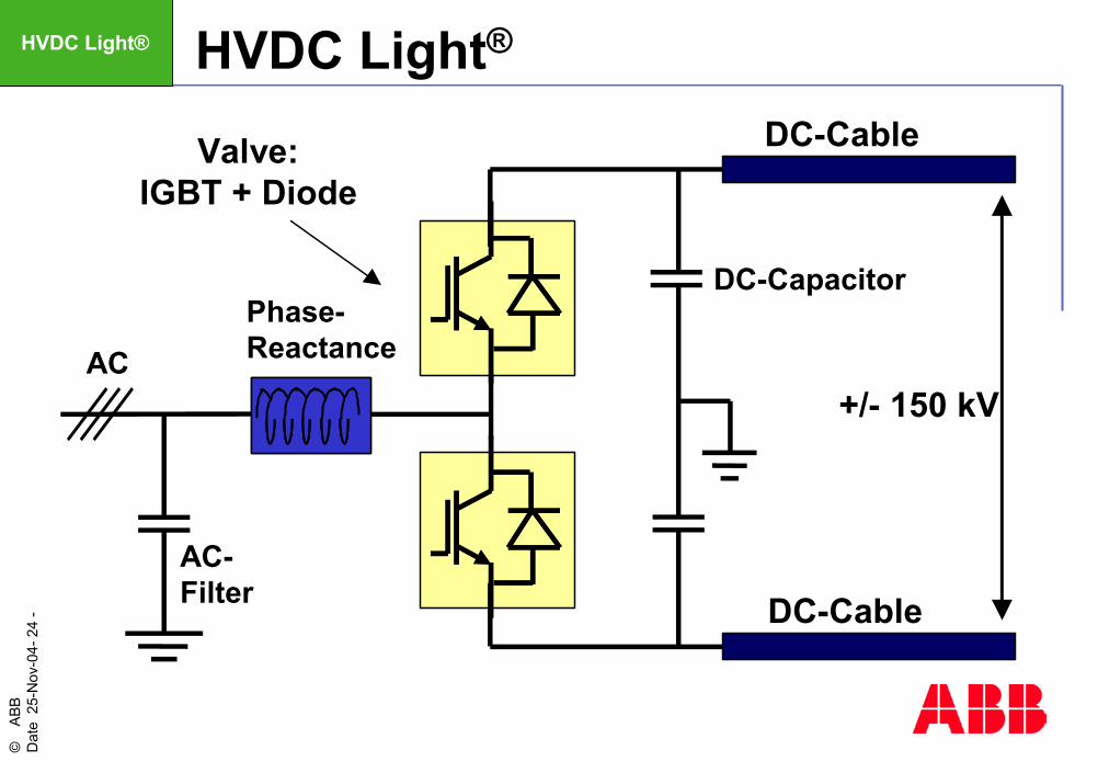
-FACTS HVDC Light®
Phase-Reactance
AC-Filter
Valve:IGBT + Diode
DC-Capacitor
DC-Cable
DC-Cable
+/- 150 kVAC
HVDC Light®
©AB
B D
ate
25-N
ov-0
4-25
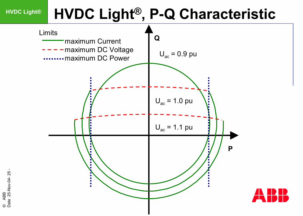
-FACTS HVDC Light®, P-Q Characteristic
P
Q
Uac = 0.9 pu
Uac = 1.0 pu
Uac = 1.1 pu
Limitsmaximum Currentmaximum DC Voltagemaximum DC Power
HVDC Light®
©AB
B D
ate
25-N
ov-0
4-26
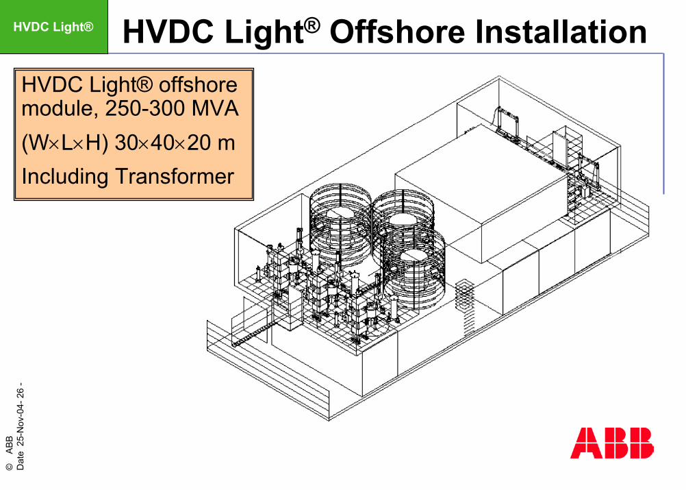
-FACTS HVDC Light® Offshore Installation
HVDC Light® offshore module, 250-300 MVA (W×L×H) 30×40×20 mIncluding Transformer
HVDC Light®
©AB
B D
ate
25-N
ov-0
4-27
-FACTS
Wind Generators
Response to Grid Faults
SVC and STATCOM
HVDC
HVDC Light®
Closing Remarks
Agenda
PICTUREJPG-FORMAT
WEB OPTIMIZED RESOLUTION
©AB
B D
ate
25-N
ov-0
4-28
-FACTS Conclusion 1
Both AC and DC are available and feasible for connecting large wind power plants to the grid.
The selection of technology depends on several parameters, a supplier with experience of both technologies should be able to advice.

©AB
B D
ate
25-N
ov-0
4-29
-FACTS Conclusion 2
An SVC at the PCC provide reactive power support to the grid at all operating scenarios and mitigates problems with flicker, stability and other quality issues.HVDC Light® is an alternative when the connection is long and/or the grid connection point is weak. With HVDC Light® it is possible to operate of the wind farm at different and/or varying frequency.