Power Electronics The Key Technology for Renewable Energy System...
67
Power Electronics – The Key Technology for Renewable Energy System Integration Frede Blaabjerg Professor, IEEE Fellow [email protected] Aalborg University Department of Energy Technology Aalborg, Denmark
-
Upload
duongkhanh -
Category
Documents
-
view
215 -
download
0
Transcript of Power Electronics The Key Technology for Renewable Energy System...
Power Electronics – The Key
Technology for Renewable Energy
System Integration
Frede Blaabjerg
Professor, IEEE Fellow
Aalborg University
Department of Energy Technology
Aalborg, Denmark
► Overview of power electronics and renewable energy systemState-of-the-art; Technology overview, global impact
► Demands for renewable energy systemsPV; Wind power; Cost of Energy; Reliabil ity, Mission Profiles, Grid Codes
OutlineOutline
2
► Power converters for renewablesPV inverters at different power; Wind power application; Power semiconductor devices
► Control for renewable systemsPV application; Wind power application
► Summary

3
Aalborg University and
Department of Energy Technology
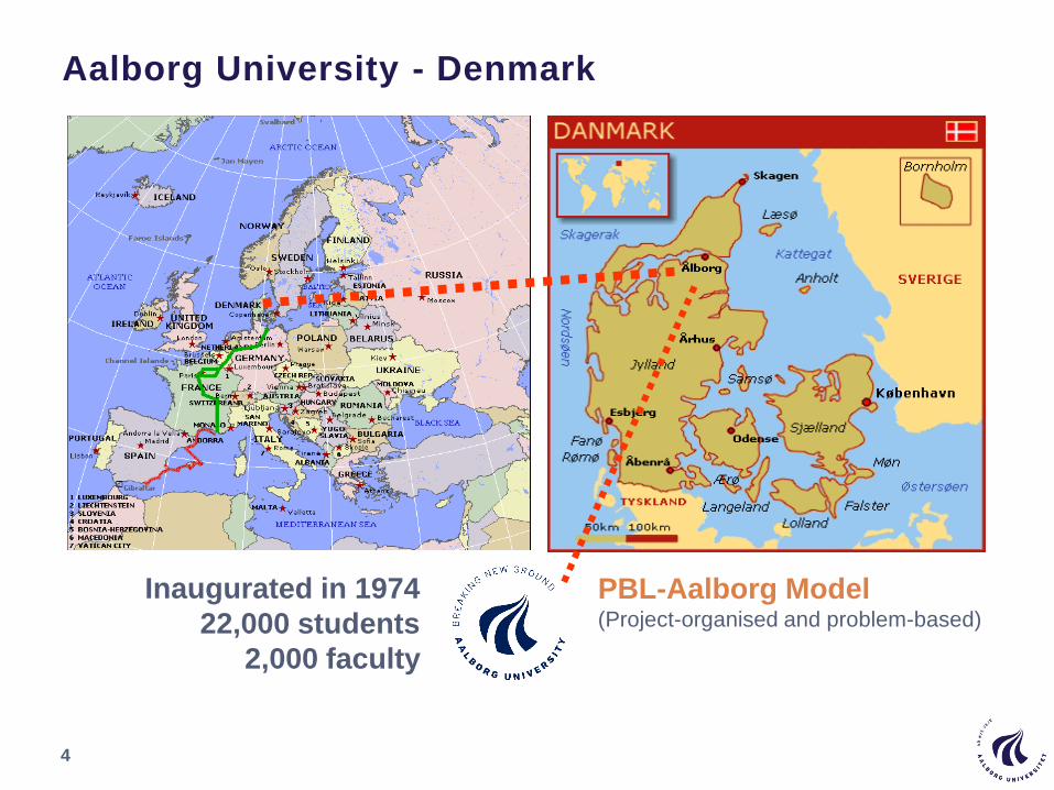
Aalborg University - Denmark
4
PBL-Aalborg Model (Project-organised and problem-based)
Inaugurated in 1974
22,000 students
2,000 faculty

Aalborg University - Campus
5
Overview of power electronics technology
and renewable energy systems
6
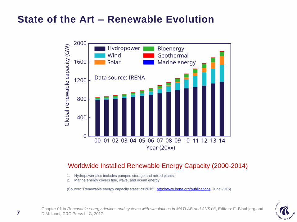
Worldwide Installed Renewable Energy Capacity (2000-2014)
1. Hydropower also includes pumped storage and mixed plants;
2. Marine energy covers tide, wave, and ocean energy
(Source: “Renewable energy capacity statistics 2015”, http://www.irena.org/publications, June 2015)
State of the Art – Renewable Evolution
7Chapter 01 in Renewable energy devices and systems with simulations in MATLAB and ANSYS, Editors: F. Blaabjerg and
D.M. Ionel, CRC Press LLC, 2017
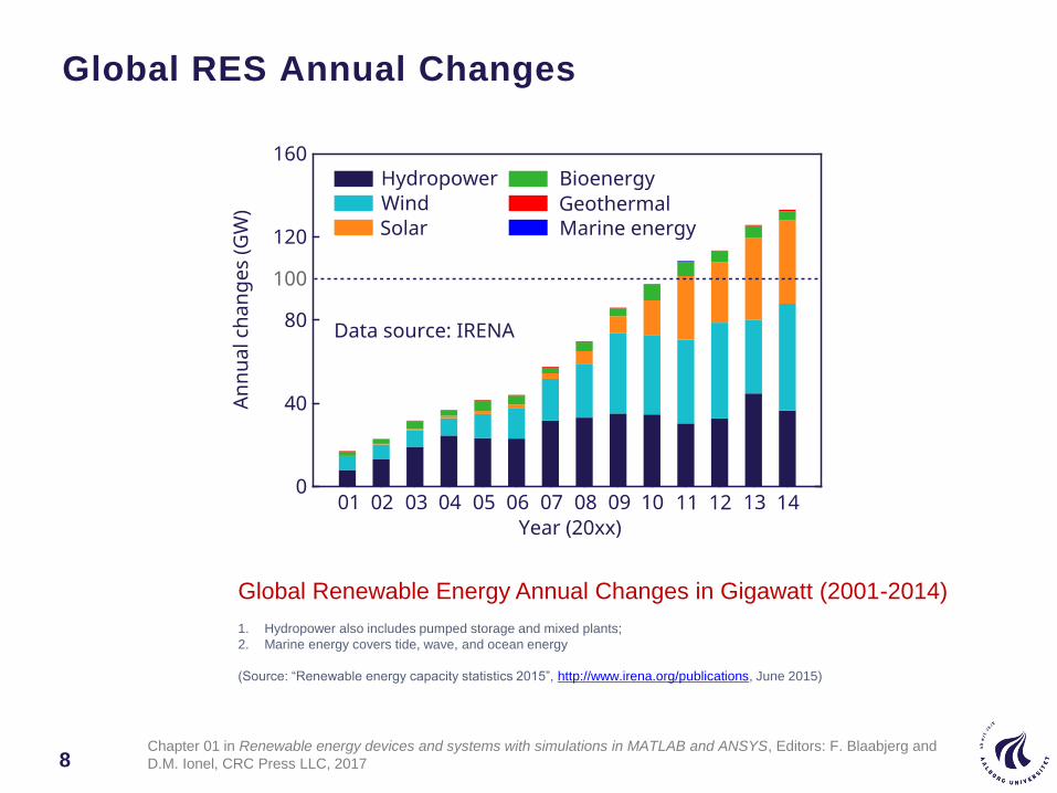
Global RES Annual Changes
8
Global Renewable Energy Annual Changes in Gigawatt (2001-2014)
1. Hydropower also includes pumped storage and mixed plants;
2. Marine energy covers tide, wave, and ocean energy
(Source: “Renewable energy capacity statistics 2015”, http://www.irena.org/publications, June 2015)
Chapter 01 in Renewable energy devices and systems with simulations in MATLAB and ANSYS, Editors: F. Blaabjerg and
D.M. Ionel, CRC Press LLC, 2017
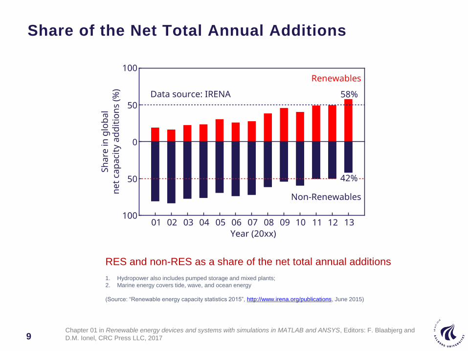
Share of the Net Total Annual Additions
9
RES and non-RES as a share of the net total annual additions
1. Hydropower also includes pumped storage and mixed plants;
2. Marine energy covers tide, wave, and ocean energy
(Source: “Renewable energy capacity statistics 2015”, http://www.irena.org/publications, June 2015)
Chapter 01 in Renewable energy devices and systems with simulations in MATLAB and ANSYS, Editors: F. Blaabjerg and
D.M. Ionel, CRC Press LLC, 2017
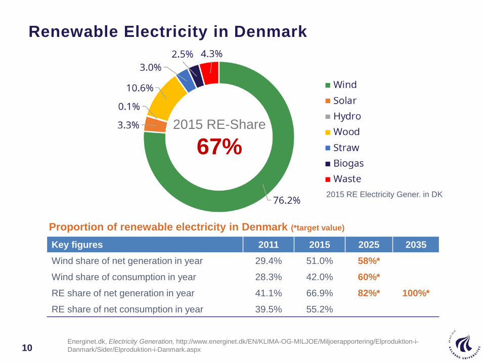
Renewable Electricity in Denmark
10
Proportion of renewable electricity in Denmark (*target value)
Key figures 2011 2015 2025 2035
Wind share of net generation in year 29.4% 51.0% 58%*
Wind share of consumption in year 28.3% 42.0% 60%*
RE share of net generation in year 41.1% 66.9% 82%* 100%*
RE share of net consumption in year 39.5% 55.2%
2015 RE Electricity Gener. in DK
2015 RE-Share
67%
Energinet.dk, Electricity Generation, http://www.energinet.dk/EN/KLIMA-OG-MILJOE/Miljoerapportering/Elproduktion-i-
Danmark/Sider/Elproduktion-i-Danmark.aspx
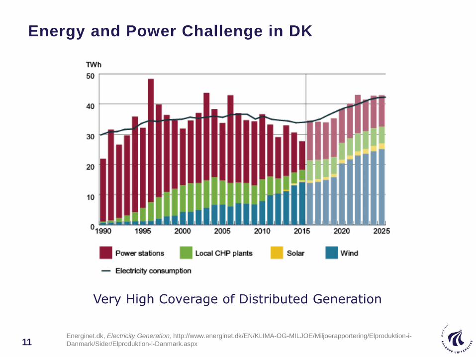
Energy and Power Challenge in DK
11
Very High Coverage of Distributed Generation
Energinet.dk, Electricity Generation, http://www.energinet.dk/EN/KLIMA-OG-MILJOE/Miljoerapportering/Elproduktion-i-
Danmark/Sider/Elproduktion-i-Danmark.aspx
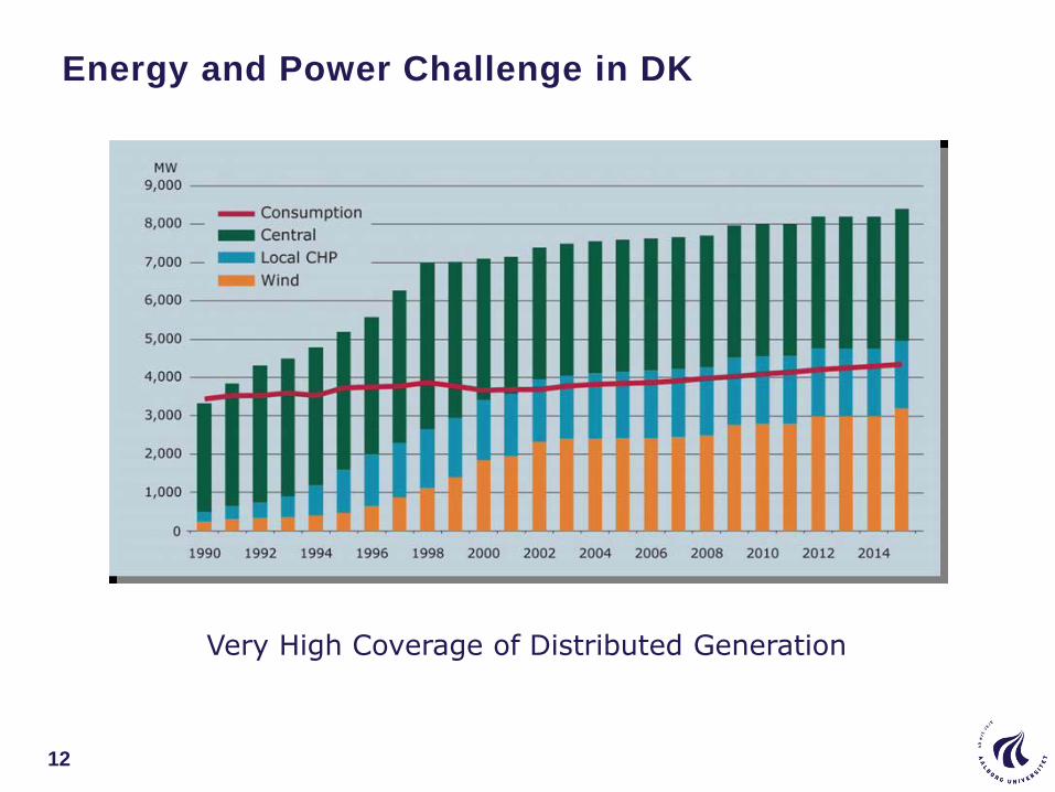
Energy and Power Challenge in DK
12
Very High Coverage of Distributed Generation
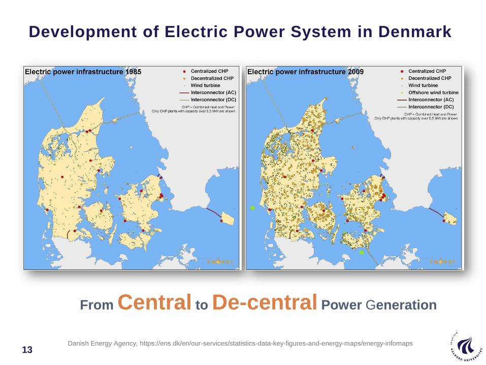
Development of Electric Power System in Denmark
13
From Central to De-central Power Generation
Danish Energy Agency, https://ens.dk/en/our-services/statistics-data-key-figures-and-energy-maps/energy-infomaps
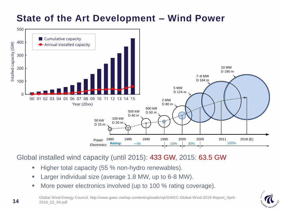
Higher total capacity (55 % non-hydro renewables).
Larger individual size (average 1.8 MW, up to 6-8 MW).
More power electronics involved (up to 100 % rating coverage).
Global installed wind capacity (until 2015): 433 GW, 2015: 63.5 GW
1980 1985 1990 1995 2000 2005 2011
50 kW
D 15 m
100 kW
D 20 m
500 kW
D 40 m
600 kW
D 50 m
2 MW
D 80 m
5 MW
D 124 m
7~8 MW
D 164 m
0% 10% 30% 100%Rating:Power
Electronics
2018 (E)
10 MW
D 190 m
State of the Art Development – Wind Power
14Global Wind Energy Council, http://www.gwec.net/wp-content/uploads/vip/GWEC-Global-Wind-2015-Report_April-
2016_22_04.pdf

DFIG: Doubly-fed induction generator
PMSG: Permanent magnet synchronous generator
IG: Induction generator
SG: Synchronous generator
Top 5 Wind Turbine Manufacturers & Technologies
15
Manufacturer Concept Rotor Diameter Power Range
Goldwind (China)PMSG
IG
70 – 109 m
110 m
1.5 – 2.5 MW
3 MW
Vestas (Denmark)DFIG
PMSG
80 –110 m
105 – 164 m
1.8 – 2 MW
3.3 – 8 MW
GE Energy (USA)DFIG
PMSG
77 – 120 m
113 m
1.5 – 2.75 MW
4.1 MW
Siemens (Germany)IG
PMSG
82 – 120 m
101 – 154 m
2.3 – 3.6 MW
3 – 6 MW
Gamesa (Spain)DFIG
PMSG
52 –114 m
128 m
0.85 – 2 MW
4.5 MW
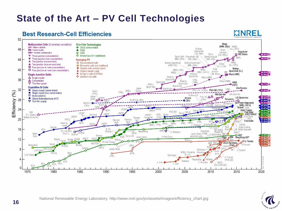
State of the Art – PV Cell Technologies
16National Renewable Energy Laboratory, http://www.nrel.gov/pv/assets/images/efficiency_chart.jpg
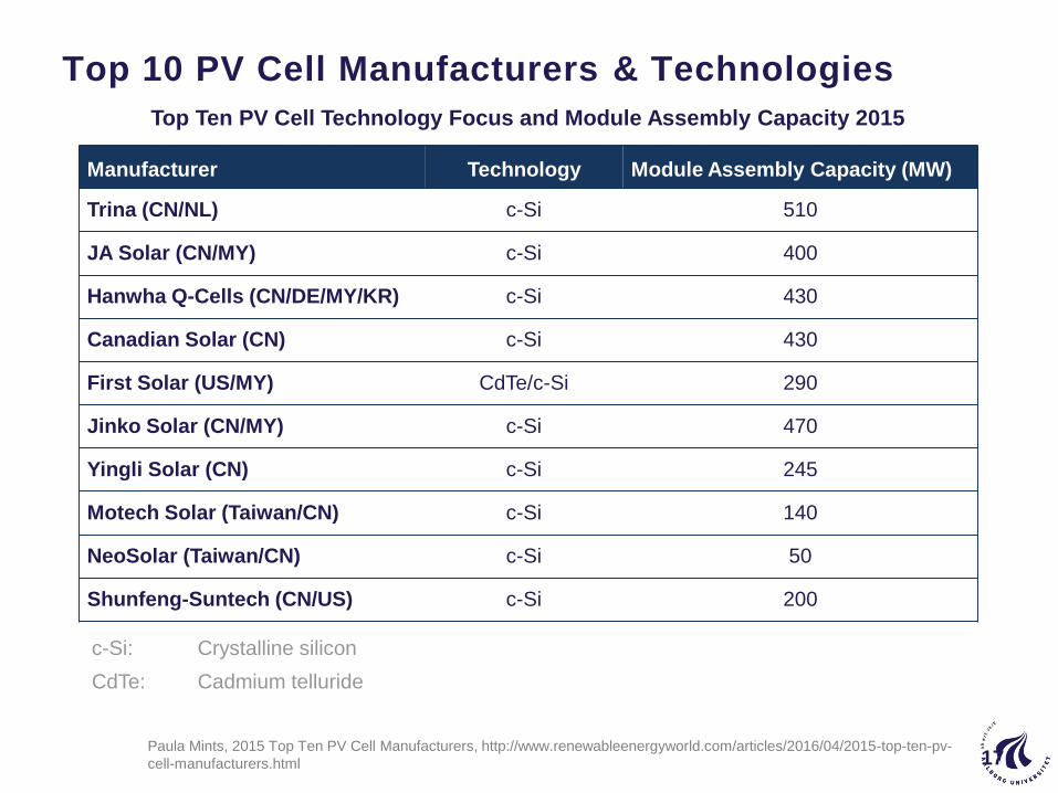
Top 10 PV Cell Manufacturers & Technologies
Manufacturer Technology Module Assembly Capacity (MW)
Trina (CN/NL) c-Si 510
JA Solar (CN/MY) c-Si 400
Hanwha Q-Cells (CN/DE/MY/KR) c-Si 430
Canadian Solar (CN) c-Si 430
First Solar (US/MY) CdTe/c-Si 290
Jinko Solar (CN/MY) c-Si 470
Yingli Solar (CN) c-Si 245
Motech Solar (Taiwan/CN) c-Si 140
NeoSolar (Taiwan/CN) c-Si 50
Shunfeng-Suntech (CN/US) c-Si 200
c-Si: Crystalline silicon
CdTe: Cadmium telluride
Top Ten PV Cell Technology Focus and Module Assembly Capacity 2015
Paula Mints, 2015 Top Ten PV Cell Manufacturers, http://www.renewableenergyworld.com/articles/2016/04/2015-top-ten-pv-
cell-manufacturers.html 17
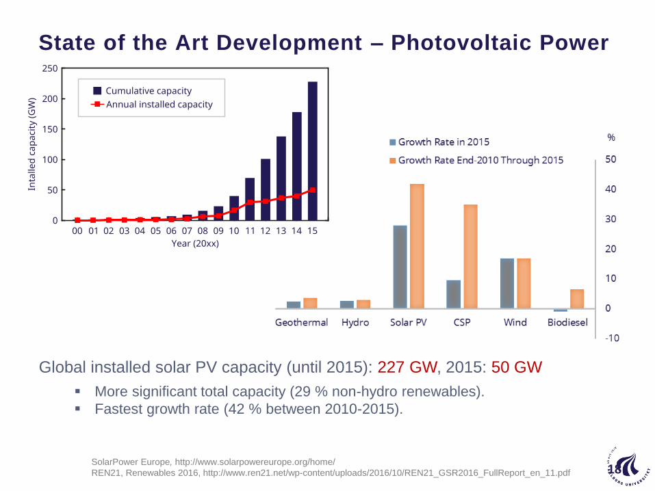
State of the Art Development – Photovoltaic Power
More significant total capacity (29 % non-hydro renewables).
Fastest growth rate (42 % between 2010-2015).
Global installed solar PV capacity (until 2015): 227 GW, 2015: 50 GW
18SolarPower Europe, http://www.solarpowereurope.org/home/
REN21, Renewables 2016, http://www.ren21.net/wp-content/uploads/2016/10/REN21_GSR2016_FullReport_en_11.pdf
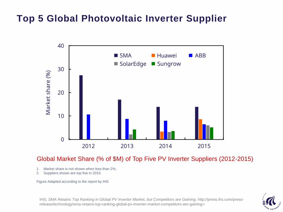
Top 5 Global Photovoltaic Inverter Supplier
19
Global Market Share (% of $M) of Top Five PV Inverter Suppliers (2012-2015)
1. Market share is not shown when less than 2%;
2. Suppliers shown are top five in 2015.
Figure Adapted according to the report by IHS
IHS, SMA Retains Top Ranking in Global PV Inverter Market, but Competitors are Gaining, http://press.ihs.com/press-
release/technology/sma-retains-top-ranking-global-pv-inverter-market-competitors-are-gaining-i
Demands for renewable energy systems
20
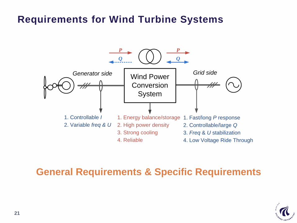
Requirements for Wind Turbine Systems
21
Wind Power
Conversion
System
1. Controllable I
2. Variable freq & U
P
Q
P
Q
1. Energy balance/storage
2. High power density
3. Strong cooling
4. Reliable
1. Fast/long P response
2. Controllable/large Q
3. Freq & U stabilization
4. Low Voltage Ride Through
Generator side Grid side
General Requirements & Specific Requirements

Input mission profiles for wind power application
22
Mission profile for wind turbines in Thyboron wind farm
► Highly variable wind speed
► Different wind classes are defined - turbulence and avg. speed
► Large power inertia to wind speed variation – stored energy in rotor.
► Large temperature inertia to ambient temp. variation – large nacelle
capacity
Wind speed Ambient temperature
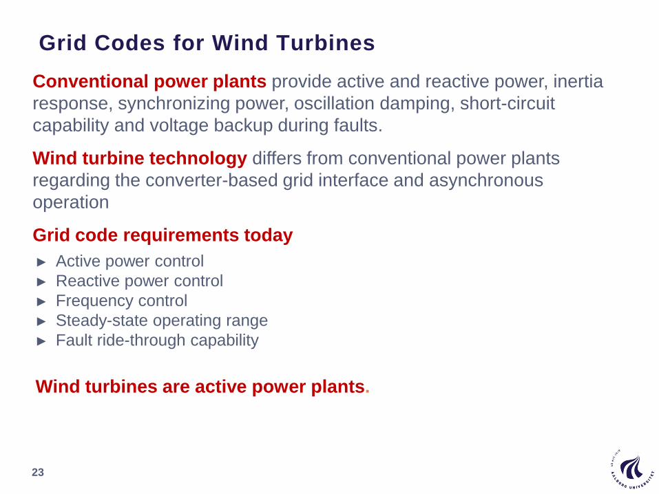
Grid Codes for Wind Turbines
23
Conventional power plants provide active and reactive power, inertia
response, synchronizing power, oscillation damping, short-circuit
capability and voltage backup during faults.
Wind turbine technology differs from conventional power plants
regarding the converter-based grid interface and asynchronous
operation
Grid code requirements today
► Active power control
► Reactive power control
► Frequency control
► Steady-state operating range
► Fault ride-through capability
Wind turbines are active power plants.
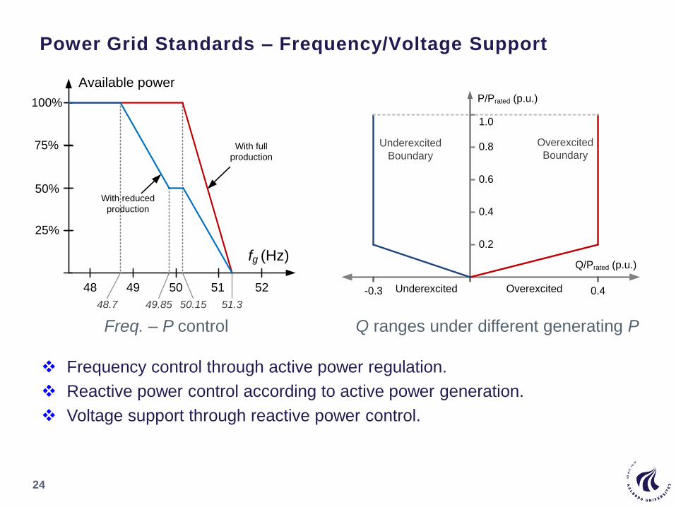
Power Grid Standards – Frequency/Voltage Support
24
Freq. – P control Q ranges under different generating P
Frequency control through active power regulation.
Reactive power control according to active power generation.
Voltage support through reactive power control.
100%
Available power
fg (Hz)
48 49 5251
51.350.15
75%
50%
25%
50
49.8548.7
With full
production
With reduced
production
P/Prated (p.u.)
Q/Prated (p.u.)
0.2
0.4
0.6
0.8
1.0
0.4OverexcitedUnderexcited-0.3
Underexcited
Boundary
Overexcited
Boundary

Power Grid Standards – Ride-Through Operation
25
0
25
75
90
100
150 500 750 1000 1500
Voltage(%)
Time (ms)
DenmarkSpain
Germany
US
Keep connected
above the curves
Grid voltage dips vs. withstand time
100%
Iq /Irated
Vg (p.u.)
0.5
0
Dead band
0.9 1.0
20%
Reactive current vs. Grid voltage dips
Withstand extreme grid voltage dips.
Contribute to grid recovery by injecting Iq.
Higher power controllability of converter.
Requirements during grid faults
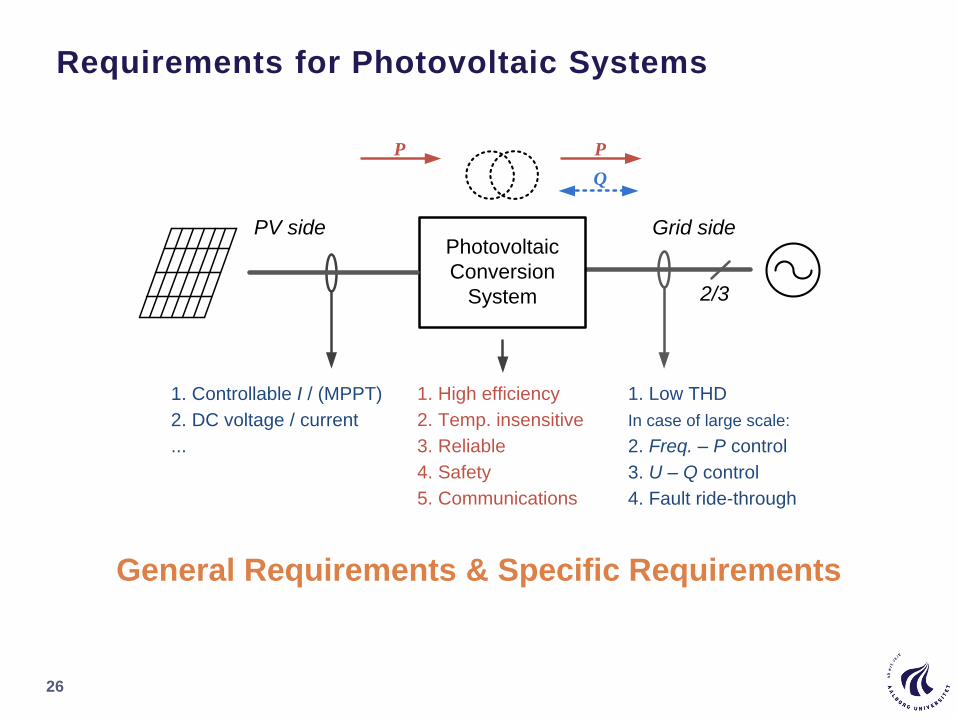
Requirements for Photovoltaic Systems
26
General Requirements & Specific Requirements
Photovoltaic
Conversion
System
1. Controllable I / (MPPT)
2. DC voltage / current
...
P P
Q
1. High efficiency
2. Temp. insensitive
3. Reliable
4. Safety
5. Communications
...
1. Low THD
In case of large scale:
2. Freq. – P control
3. U – Q control
4. Fault ride-through
...
PV side Grid side
2/3
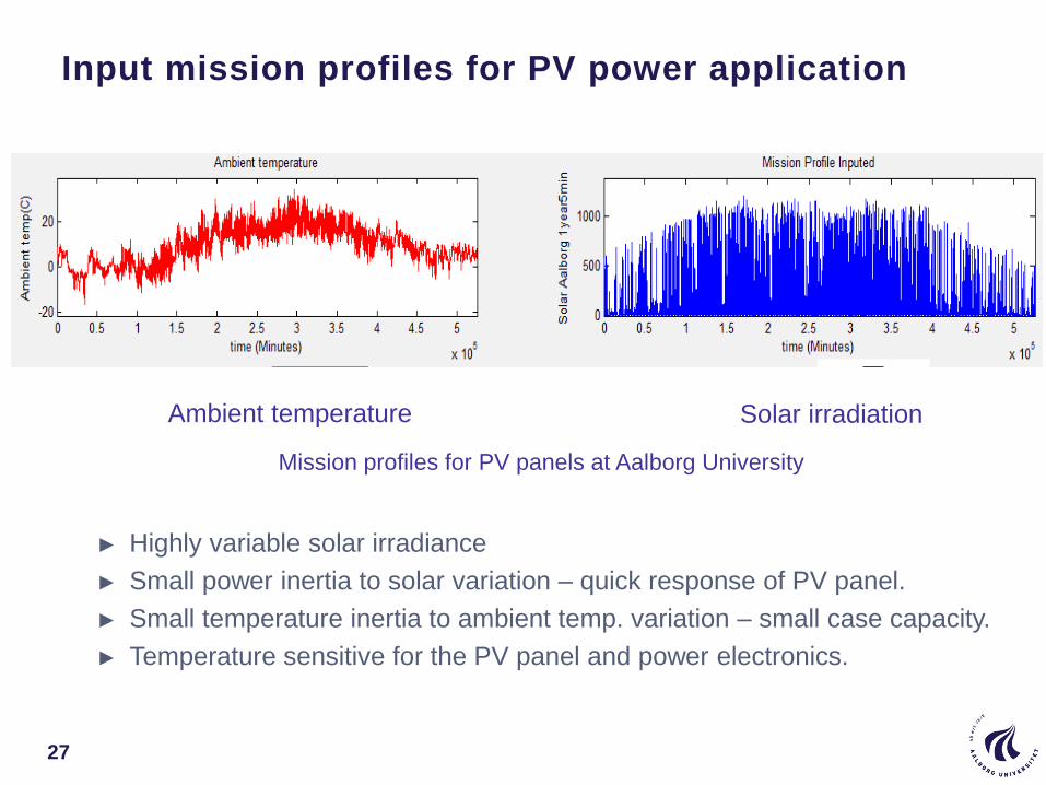
Input mission profiles for PV power application
27
Mission profiles for PV panels at Aalborg University
► Highly variable solar irradiance
► Small power inertia to solar variation – quick response of PV panel.
► Small temperature inertia to ambient temp. variation – small case capacity.
► Temperature sensitive for the PV panel and power electronics.
Solar irradiationAmbient temperature
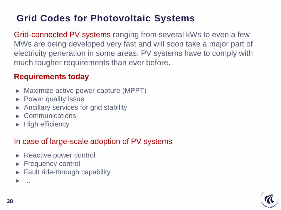
Grid-connected PV systems ranging from several kWs to even a few
MWs are being developed very fast and will soon take a major part of
electricity generation in some areas. PV systems have to comply with
much tougher requirements than ever before.
Requirements today
► Maximize active power capture (MPPT)
► Power quality issue
► Ancillary services for grid stability
► Communications
► High efficiency
In case of large-scale adoption of PV systems
► Reactive power control
► Frequency control
► Fault ride-through capability
► …
Grid Codes for Photovoltaic Systems
28
Typ
ica
l L
CO
E r
an
ge
s U
SD
/ k
Wh
Cost of fossil fuel
generation
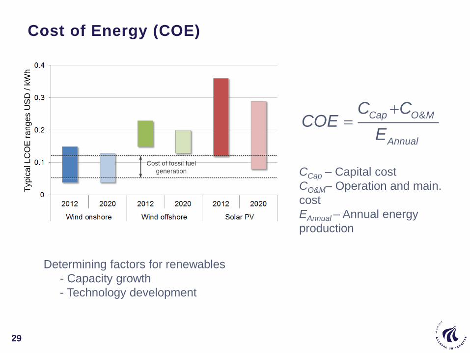
&Cap O M
Annual
C CCOE
E
CCap – Capital cost
CO&M– Operation and main.
cost
EAnnual – Annual energy
production
Determining factors for renewables
- Capacity growth
- Technology development
Cost of Energy (COE)
29
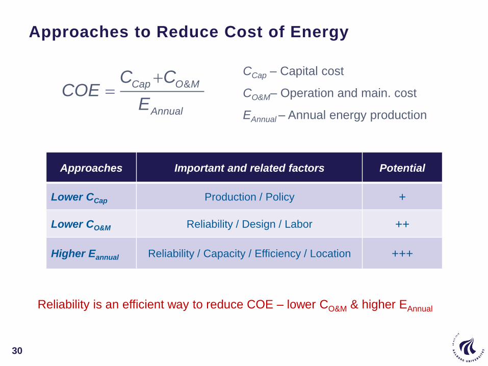
&Cap O M
Annual
C CCOE
E
CCap – Capital cost
CO&M– Operation and main. cost
EAnnual – Annual energy production
Approaches Important and related factors Potential
Lower CCap Production / Policy +
Lower CO&M Reliability / Design / Labor ++
Higher Eannual Reliability / Capacity / Efficiency / Location +++
Reliability is an efficient way to reduce COE – lower CO&M & higher EAnnual
Approaches to Reduce Cost of Energy
30
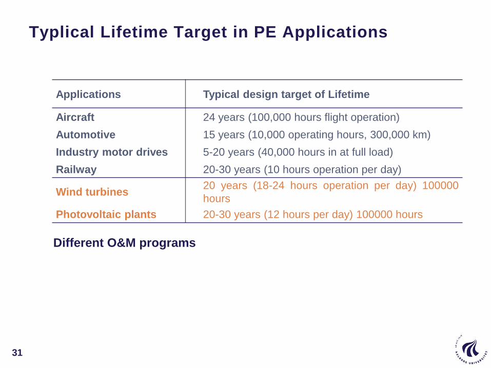
Applications Typical design target of Lifetime
Aircraft 24 years (100,000 hours flight operation)
Automotive 15 years (10,000 operating hours, 300,000 km)
Industry motor drives 5-20 years (40,000 hours in at full load)
Railway 20-30 years (10 hours operation per day)
Wind turbines20 years (18-24 hours operation per day) 100000
hours
Photovoltaic plants 20-30 years (12 hours per day) 100000 hours
Different O&M programs
Typlical Lifetime Target in PE Applications
31
Power converters for renewables
application
32
PV Inverter System Configurations
33
AC Bus
AC
DC
AC
DC
DC
DC
DC
DC
AC
DC
AC
DC
AC
DC Bus
DC
PV Strings
PV String
AC-Module
Inverter
3 phase1 or 3 phase1 phase 1 or 3 phase
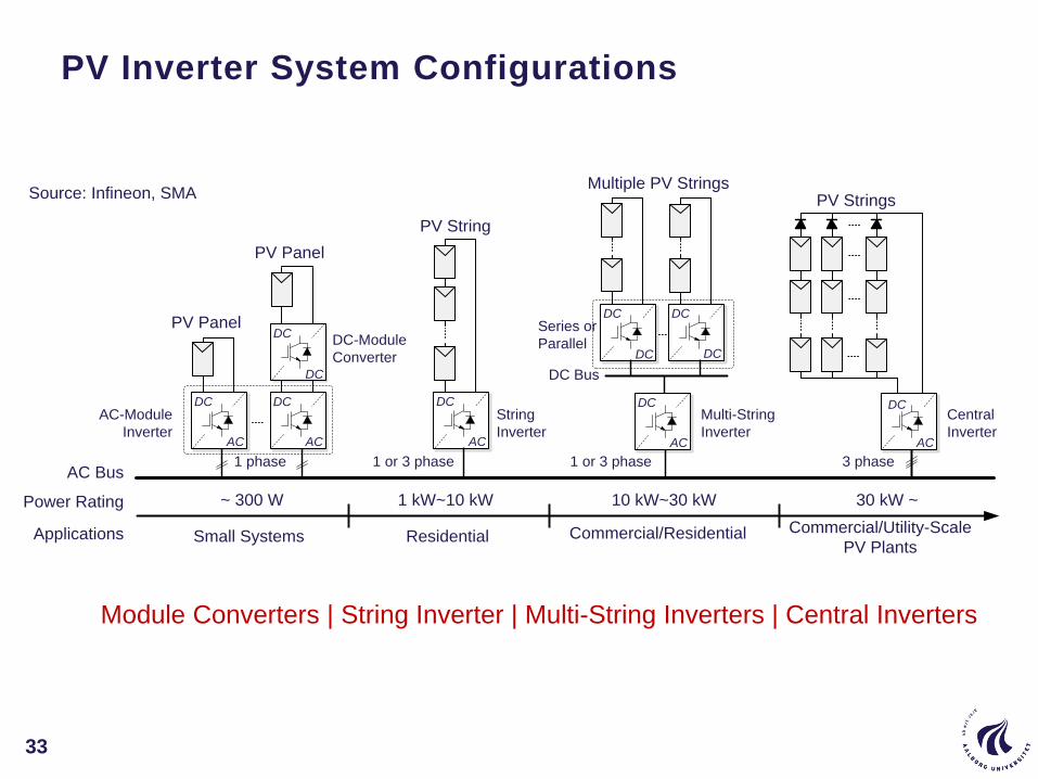
Source: Infineon, SMA
Power Rating ~ 300 W 1 kW~10 kW 10 kW~30 kW 30 kW ~
Applications Small Systems Residential Commercial/Residential Commercial/Utility-Scale
PV Plants
String
Inverter
Multi-String
Inverter
Central
Inverter
Multiple PV Strings
PV PanelDC
DC
PV Panel
DC-Module
Converter
Series or
Parallel
Module Converters | String Inverter | Multi-String Inverters | Central Inverters
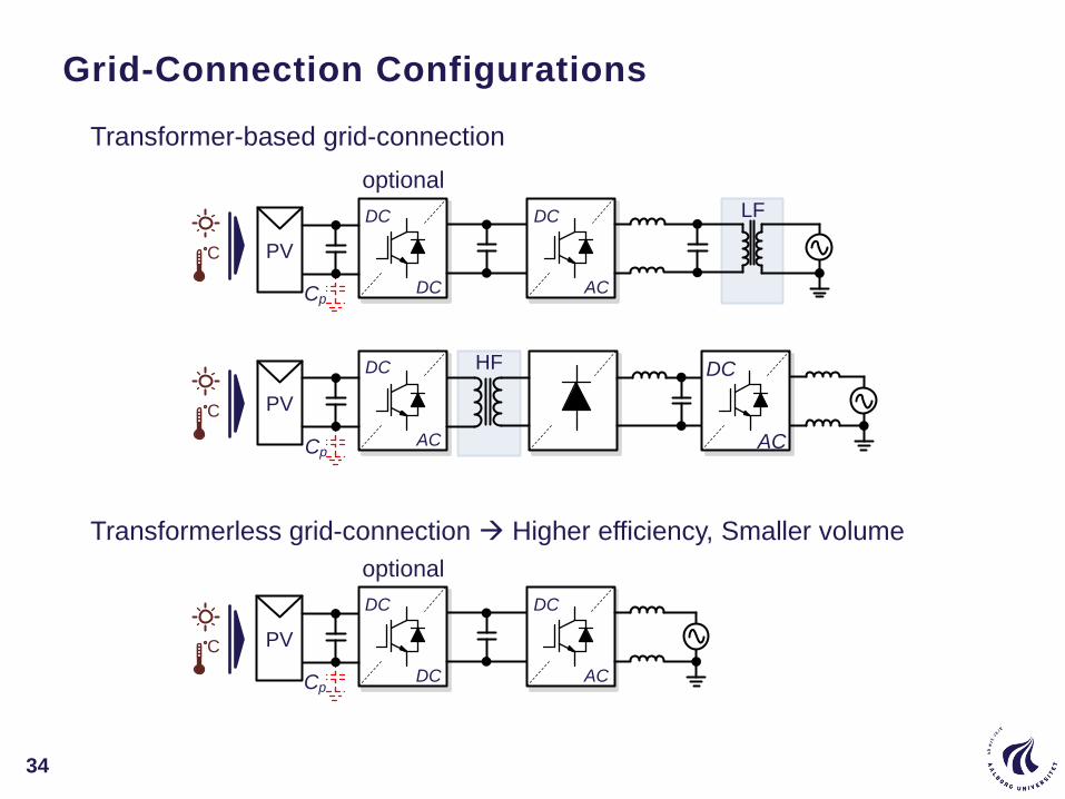
Grid-Connection Configurations
34
LF
DC
AC
DC
AC
DC
DC AC
HF
PV
PV
DC
Cp
Cp
DC
DC AC
PV
DC
Cp
optional
optional
C
C
C
Transformer-based grid-connection
Transformerless grid-connection Higher efficiency, Smaller volume
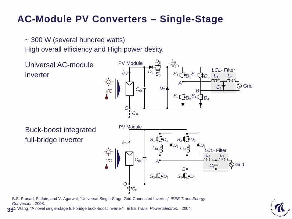
AC-Module PV Converters – Single-Stage
35
~ 300 W (several hundred watts)
High overall efficiency and High power desity.
Cdc
O
Grid
D1
D2
D3
D4
A
B
PV Module
iPV
CP
S1
S2
S3
S4
Cf
L1 L2
LCL- FilterS5
D5
D6
D7
L0
C
Cdc
O
Grid
D1
D2
D3
D4
A
B
PV Module
iPV
CP
S1
S2
S3
S4
Cf
L1 L2
LCL- FilterD5Lb1
C
D6Lb2
B.S. Prasad, S. Jain, and V. Agarwal, "Universal Single-Stage Grid-Connected Inverter," IEEE Trans Energy
Conversion, 2008.
C. Wang "A novel single-stage full-bridge buck-boost inverter", IEEE Trans. Power Electron., 2004.
Universal AC-module
inverter
Buck-boost integrated
full-bridge inverter

String/Multi-String PV Inverters
36
1 kW ~ 30 kW (tens kilowatts)
High efficiency and also Emerging for modular configuration in medium
and high power PV systems.
No common mode voltage VPE free for high frequency low leakage current
Max efficiency 96.5% due to reactive power exchange between the filter and CPV during freewheeling
and due to the fact that 2 switched are simultaneously switched every switching
This topology is not special suited to transformerless PV inverter due to low efficiency!
Bipolar Modulation is used:
Cdc
O
Gri
d
D1
D2
D3
D4
A
B
PV Strings
iPV
CP
S1
S2
S3
S4
Full-Bridge
Cf
L1 L2
LCL- Filter
C
Leakage circulating current

H5 Transformerless Inverter (SMA)
H6 Transformerless Inverter (Ingeteam)
Efficiency of up to 98%
Low leakage current and EMI
Unipolar voltage accross the filter,
leading to low core losses
High efficiency
Low leakage current and EMI
DC bypass switches rating: Vdc/2
Unipolar voltage accross the filter
Cdc
D5
O
Grid
LCL- Filter
D1
D2
D3
D4
A
B
PV Strings
iPVS3
S4
Cf
L1 L2S1
S2
S5
Full-Bridge
DC path
C
Cdc1
Cdc2
D5
D6
D7
D8
O
Grid
LCL- Filter
D1
D2
D3
D4
A
B
PV Strings
iPV S3
S4
Cf
L1 L2S1
S2S6
S5
Full-Bridge
DC path
C
Transformerless String Inverters
37
M. Victor, F. Greizer, S. Bremicker, and U. Hubler, U.S. Patent 20050286281 A1, Dec 29, 2005.
R. Gonzalez, J. Lopez, P. Sanchis, and L. Marroyo, "Transformerless inverter for single-phase photovoltaic
systems," IEEE Trans. Power Electron., 2007.

Constant voltage-to-ground Low leakage current, suitable
for transformerless PV applications.
High DC-link voltage ( > twice of the grid peak voltage)
A
B
Cdc1
O
Grid
LCL- Filter
D3
PV Strings
iPV
S3
Cf
L1 L2C
D1S1
D2S2
D4
S4
Cdc2
NPC Transformerless String Inverters
38
Neutral Point Clamped (NPC) converter for PV applications
P. Knaup, International Patent Application, Publication Number: WO 2007/048420 A1, Issued May 3, 2007.
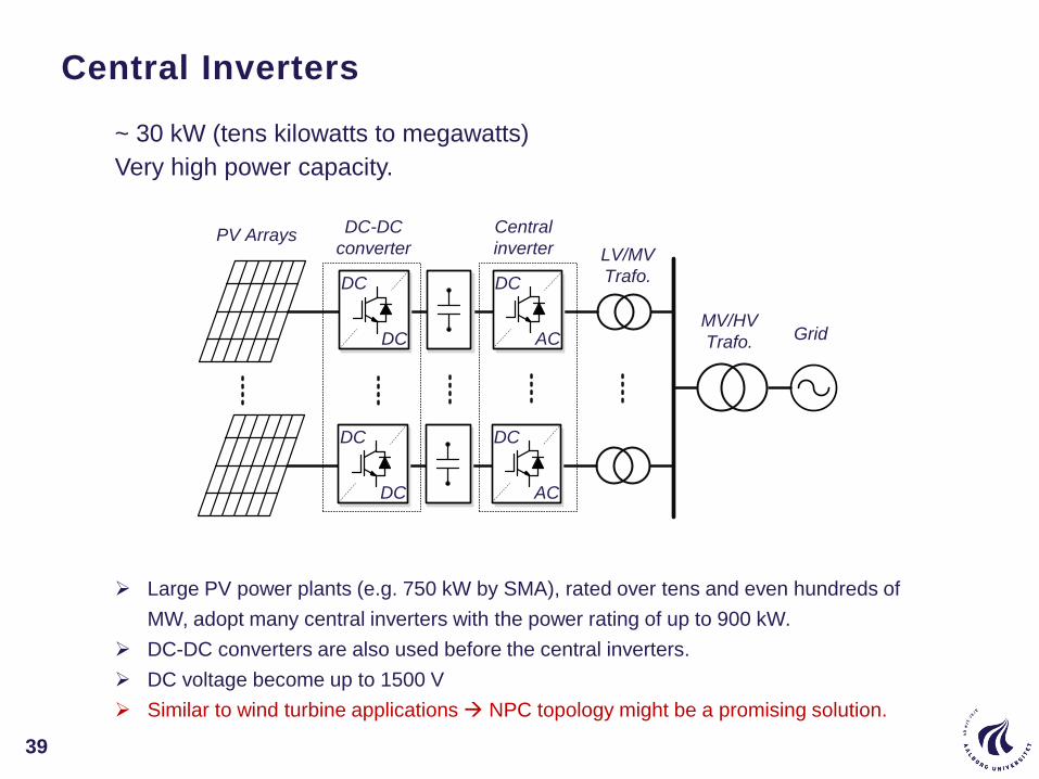
Large PV power plants (e.g. 750 kW by SMA), rated over tens and even hundreds of
MW, adopt many central inverters with the power rating of up to 900 kW.
DC-DC converters are also used before the central inverters.
DC voltage become up to 1500 V
Similar to wind turbine applications NPC topology might be a promising solution.
Central
inverter
DC
AC
DC
DC
DC
AC
DC
DC
DC-DC
converterPV Arrays
LV/MV
Trafo.
MV/HV
Trafo. Grid
Central Inverters
39
~ 30 kW (tens kilowatts to megawatts)
Very high power capacity.
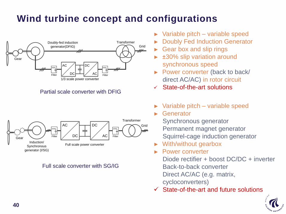
Wind turbine concept and configurations
40
Doubly-fed induction
generator(DFIG)
AC
DC
DC
AC
Grid
Filter
Gear
Transformer
1/3 scale power converter
Filter
Induction/
Synchronous
generator (I/SG)
AC
DC
DC
AC
Grid
Filter FilterGear
Transformer
Full scale power converter
► Variable pitch – variable speed
► Doubly Fed Induction Generator
► Gear box and slip rings
► ±30% slip variation around
synchronous speed
► Power converter (back to back/
direct AC/AC) in rotor circuit
State-of-the-art solutions
► Variable pitch – variable speed
► Generator
Synchronous generator
Permanent magnet generator
Squirrel-cage induction generator
► With/without gearbox
► Power converter
Diode rectifier + boost DC/DC + inverter
Back-to-back converter
Direct AC/AC (e.g. matrix,
cycloconverters)
State-of-the-art and future solutions
Partial scale converter with DFIG
Full scale converter with SG/IG
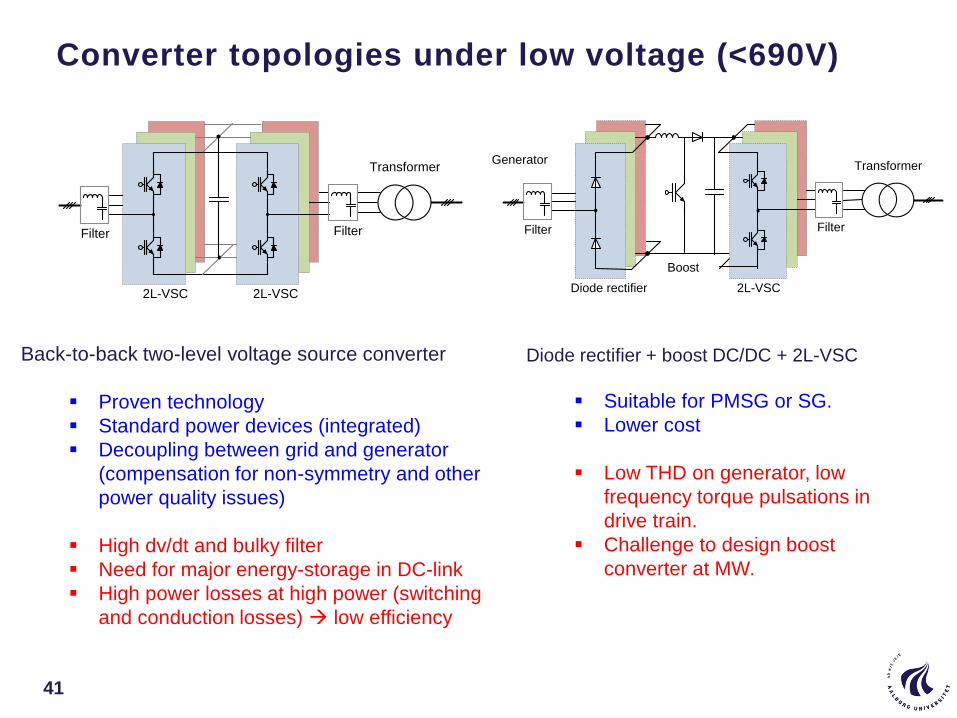
Converter topologies under low voltage (<690V)
41
Back-to-back two-level voltage source converter
Proven technology
Standard power devices (integrated)
Decoupling between grid and generator
(compensation for non-symmetry and other
power quality issues)
High dv/dt and bulky filter
Need for major energy-storage in DC-link
High power losses at high power (switching
and conduction losses) low efficiency
Transformer
2L-VSC
Filter Filter
2L-VSC
Transformer
Filter Filter
Boost
2L-VSCDiode rectifier
Generator
Diode rectifier + boost DC/DC + 2L-VSC
Suitable for PMSG or SG.
Lower cost
Low THD on generator, low
frequency torque pulsations in
drive train.
Challenge to design boost
converter at MW.
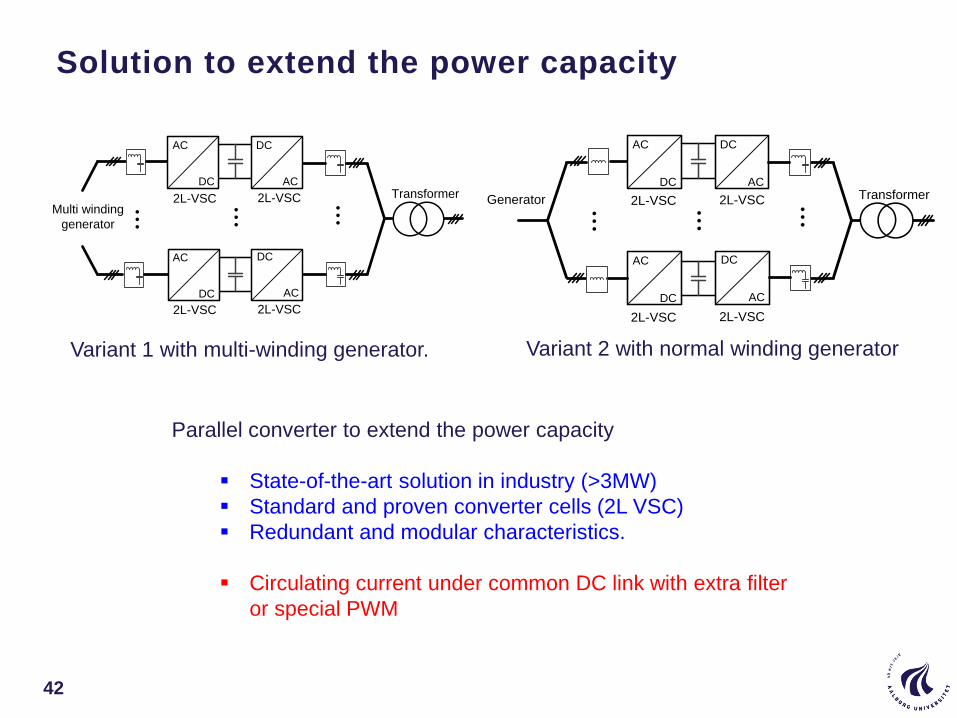
Solution to extend the power capacity
42
...Multi winding
generator
AC
DC
DC
AC
AC
DC
DC
AC
...
...
Transformer2L-VSC 2L-VSC
2L-VSC 2L-VSC
...
...
Transformer
AC
DC
DC
AC
AC
DC
DC
AC
...
Generator 2L-VSC 2L-VSC
2L-VSC 2L-VSC
Variant 2 with normal winding generatorVariant 1 with multi-winding generator.
Parallel converter to extend the power capacity
State-of-the-art solution in industry (>3MW)
Standard and proven converter cells (2L VSC)
Redundant and modular characteristics.
Circulating current under common DC link with extra filter
or special PWM
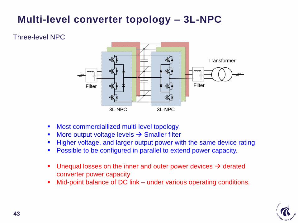
Multi-level converter topology – 3L-NPC
43
Transformer
3L-NPC
Filter Filter
3L-NPC
Three-level NPC
Most commerciallized multi-level topology.
More output voltage levels Smaller filter
Higher voltage, and larger output power with the same device rating
Possible to be configured in parallel to extend power capacity.
Unequal losses on the inner and outer power devices derated
converter power capacity
Mid-point balance of DC link – under various operating conditions.
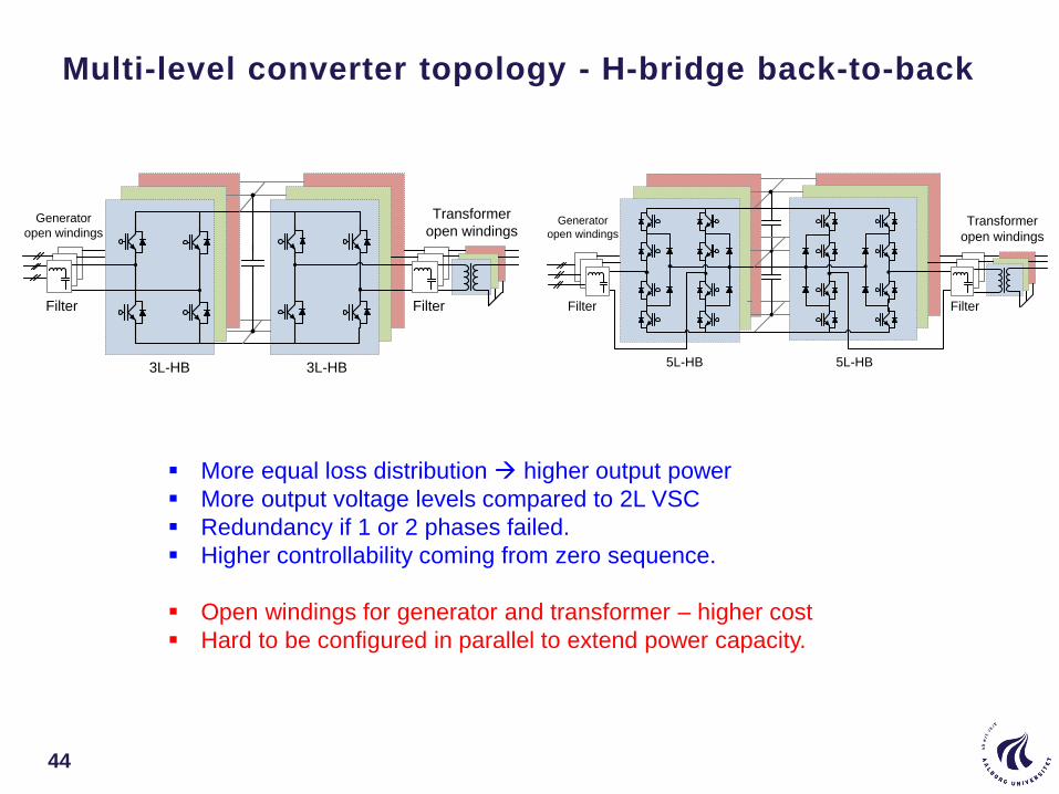
Multi-level converter topology - H-bridge back-to-back
44
Transformer
open windings
Filter Filter
3L-HB 3L-HB
Generator
open windings
5L-HB
Transformer
open windings
5L-HB
Filter Filter
Generator
open windings
More equal loss distribution higher output power
More output voltage levels compared to 2L VSC
Redundancy if 1 or 2 phases failed.
Higher controllability coming from zero sequence.
Open windings for generator and transformer – higher cost
Hard to be configured in parallel to extend power capacity.
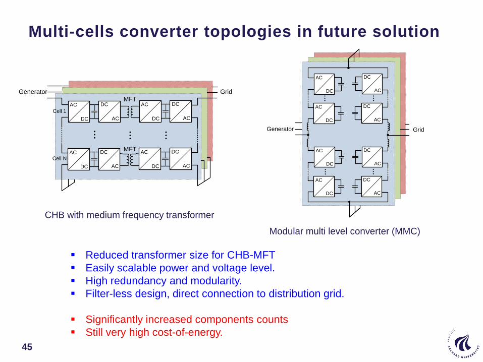
Multi-cells converter topologies in future solution
45
...
Cell 1
Cell N
...
AC
DC
DC
AC
AC
DC
DC
AC
...
AC
DC
DC
AC
AC
DC
DC
AC
MFT
MFT
GridGenerator ...
AC
DC
DC
AC...AC
DC
DC
AC
DC
AC...
DC
AC
...AC
DC
AC
DC
GridGenerator
CHB with medium frequency transformer
Modular multi level converter (MMC)
Reduced transformer size for CHB-MFT
Easily scalable power and voltage level.
High redundancy and modularity.
Filter-less design, direct connection to distribution grid.
Significantly increased components counts
Still very high cost-of-energy.

IGBT module IGBT Press-packIGCT Press-
pack
SiC-MOSFET
modulePower Density Low High High Low
Reliability Moderate High High Unknown
Cost High High High
Failure mode Open circuit Short circuit Short circuit Open circuitEasy maintenance + - - +
Insulation of heat sink + - - +Snubber requirement - - + -Thermal resistance Large Small Small Moderate
Switching loss Low Moderate Moderate LowConduction loss Moderate Moderate Moderate Large
Gate driver Moderate Moderate Large Small
Major manufacturersInfineon, Semikron,
Mitsubishi, ABBWestcode, ABB ABB
Cree, Rohm,
MitsubishiVoltage ratings 1.7 kV-6.5 kV 2.5 kV / 4.5 kV 4.5 kV / 6.5 kV 1.2 kV / 10 kV
Max. current ratings 1.5 kV - 750 A 2.3 kA / 2.4 kA 3.6 kA / 3.8 kA 180 A / 20 A
Potential power devices for wind power
46

Controls for renewable energy systems
47
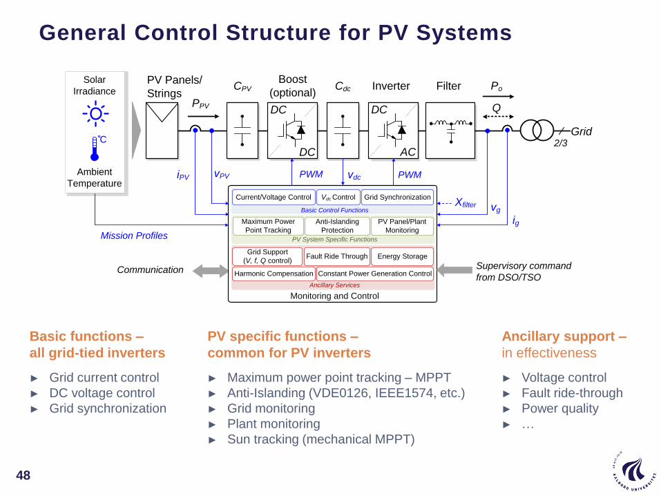
Basic functions –
all grid-tied inverters
► Grid current control
► DC voltage control
► Grid synchronization
PV specific functions –
common for PV inverters
► Maximum power point tracking – MPPT
► Anti-Islanding (VDE0126, IEEE1574, etc.)
► Grid monitoring
► Plant monitoring
► Sun tracking (mechanical MPPT)
Ancillary support –
in effectiveness
► Voltage control
► Fault ride-through
► Power quality
► …
PV Panels/
StringsPPV
Boost
(optional)
iPV vPV
vg
ig
Q
Ambient
Temperature
Solar
Irradiance
DC
DC
DC
AC
CPV Cdc Inverter Filter
vdc PWMPWM
Xfilter
Communication Supervisory command
from DSO/TSO
Mission Profiles
Grid2/3
PV Panel/Plant
Monitoring
Maximum Power
Point Tracking
Grid Support
(V, f, Q control)Energy Storage
Ancillary Services
PV System Specific Functions
Basic Control Functions
Current/Voltage Control
Fault Ride Through
Grid SynchronizationVdc Control
Monitoring and Control
Anti-Islanding
Protection
Harmonic Compensation Constant Power Generation Control
Po
C
General Control Structure for PV Systems
48
Maximum Power Point Tracking (MPPT)
49
0 5 10 15 20 250
1
2
3
4
5
0
20
40
60
80
Voltage (V)
Cu
rre
nt (A
)
Po
we
r (W
)
0
1
2
3
4
5
Cu
rre
nt (A
)
600 W/m2
800 W/m2
1000 W/m2
50 ºC 2
5 ºC 0
ºC
MPP MPP
uphill downhill uphill downhill
top
top
0
20
40
60
80
Po
we
r (W
)
0 5 10 15 20 25Voltage (V)
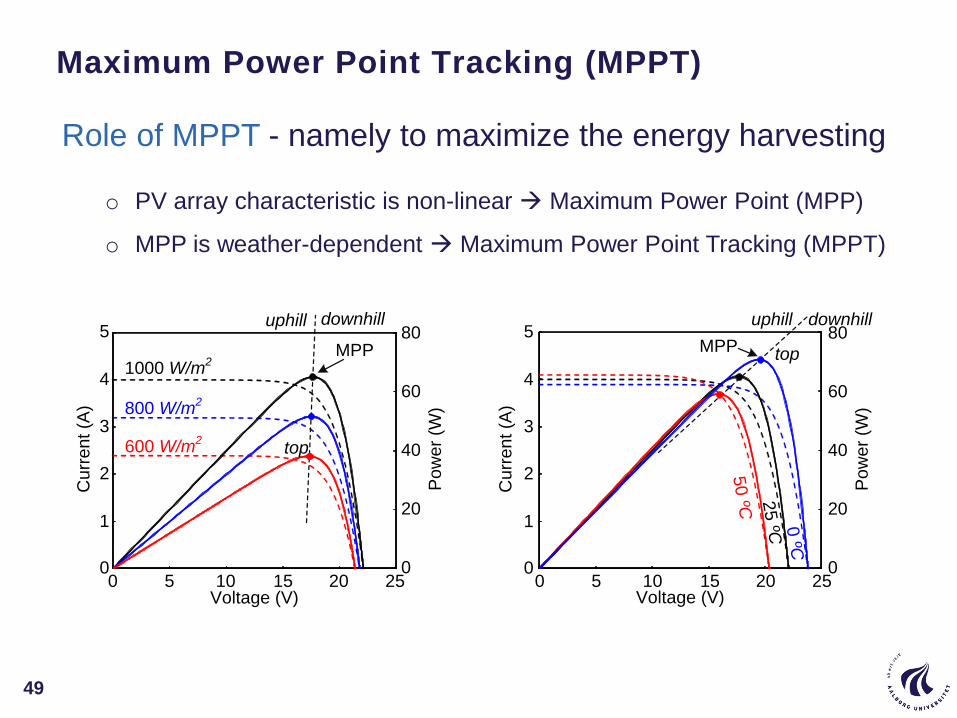
Role of MPPT - namely to maximize the energy harvesting
o PV array characteristic is non-linear Maximum Power Point (MPP)
o MPP is weather-dependent Maximum Power Point Tracking (MPPT)
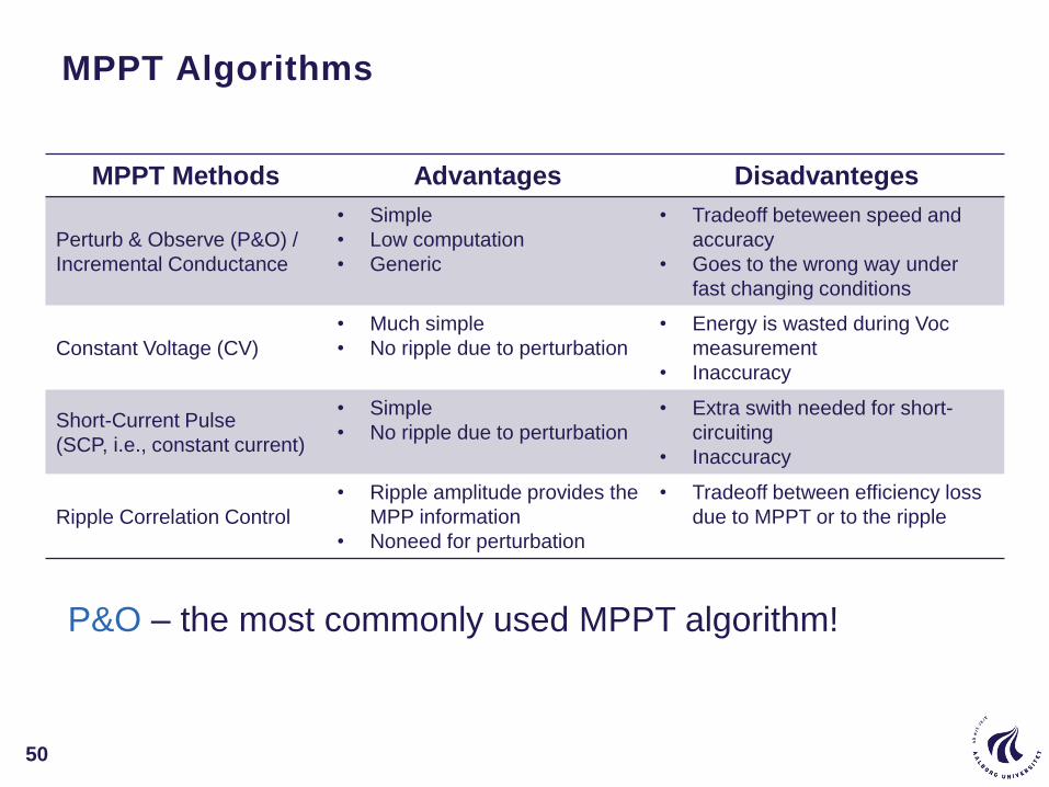
MPPT Algorithms
50
MPPT Methods Advantages Disadvanteges
Perturb & Observe (P&O) /
Incremental Conductance
• Simple
• Low computation
• Generic
• Tradeoff beteween speed and
accuracy
• Goes to the wrong way under
fast changing conditions
Constant Voltage (CV)
• Much simple
• No ripple due to perturbation
• Energy is wasted during Voc
measurement
• Inaccuracy
Short-Current Pulse
(SCP, i.e., constant current)
• Simple
• No ripple due to perturbation
• Extra swith needed for short-
circuiting
• Inaccuracy
Ripple Correlation Control
• Ripple amplitude provides the
MPP information
• Noneed for perturbation
• Tradeoff between efficiency loss
due to MPPT or to the ripple
P&O – the most commonly used MPPT algorithm!

Example of MPPT Control
51
Experiments of P&O on a 3-kW double-stage system:
0 4 8 12 16 20 24Time of a day (hour)
0
1
2
3
PV
po
we
r (k
W)
Red: theoretical power
Black: MPPT power
0 4 8 12 16 20 24Time of a day (hour)
0
1
2
3
PV
po
we
r (k
W)
Red: theoretical power
Black: MPPT power
Cloudy Day
Clear Day

Constant Power Generation (CPG) Concept
CPG – one of the Active Power Control (APC) functions
Y. Yang, F. Blaabjerg, and H. Wang, "Constant power generation of photovoltaic systems considering the distributed
grid capacity," in Proc. of APEC, pp. 379-385, 16-20 Mar. 2014.
Extend the CPG function for WTS in Denmark to wide-scale PV applications?
Gradient
production
constraint
Time
Active
Po
we
r
Possible active power
MPPT
control
MPPT
control
Delta production
constraint
Absolute (constant)
production constraint
Power ramp
constraint
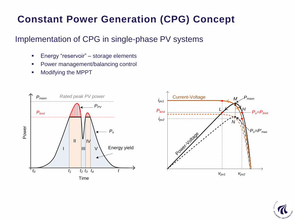
Constant Power Generation (CPG) Concept
Implementation of CPG in single-phase PV systems
Energy “reservoir” – storage elements
Power management/balancing control
Modifying the MPPT
Time
Po
we
r
Pmaxn
I III V
Po
Energy yield
t0 t1 t2 t3 t4 t
II IV
PPV
Plimit
Rated peak PV power
Pow
er-V
olta
ge
Pmaxn
vpv1 vpv2
Current-Voltageipv1
ipv2
Po=PlimitL H
M
N
Plimit
Po=P'max
0
500
1000
1500
2000
2500
3000
3500
200 250 300 350 400 4500
500
1000
1500
2000
2500
3000
3500
200 250 300 350 400 450
0
500
1000
1500
2000
2500
3000
3500
10:43:37 10:44:27 10:45:17 10:46:07 10:46:57 10:47:47 10:48:37 10:49:27 10:50:17
Available PV power
0
500
1000
1500
2000
2500
3000
3500
10:10:00 10:10:50 10:11:40 10:12:30 10:13:20 10:14:10 10:15:00 10:15:50 10:16:40
Actual PV
output power
10:43:37 10:45:17 10:46:57 10:48:37 10:50:170
0.5
1
1.5
2
2.5
3
3.5
PV
po
we
r (k
W)
CPG MPPTMPPT
2.4 kW
(80 % of rated)
Available PV power
Actual PV
output power
10:10:00 10:11:40 10:13:20 10:15:00 10:16:400
0.5
1
1.5
2
2.5
3
3.5
PV
po
we
r (k
W)
CPG MPPTMPPT
2.4 kW
(80 % of rated)
Ideal
Experiments
with CPG control
MPPT operation
CPG operation
0
0.5
1
1.5
2
2.5
3
3.5
PV
po
we
r (k
W)
200 250 300 350 400 450
Ideal
Experiments
with CPG control
MPPT operation
CPG operation
0
0.5
1
1.5
2
2.5
3
3.5
PV
po
we
r (k
W)
200 250 300 350 400 450
Time (hh:mm:ss) Time (hh:mm:ss)
PV voltage (V) PV voltage (V)
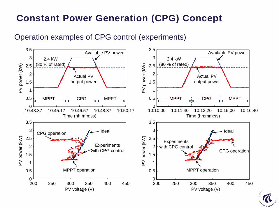
Constant Power Generation (CPG) Concept
Operation examples of CPG control (experiments)
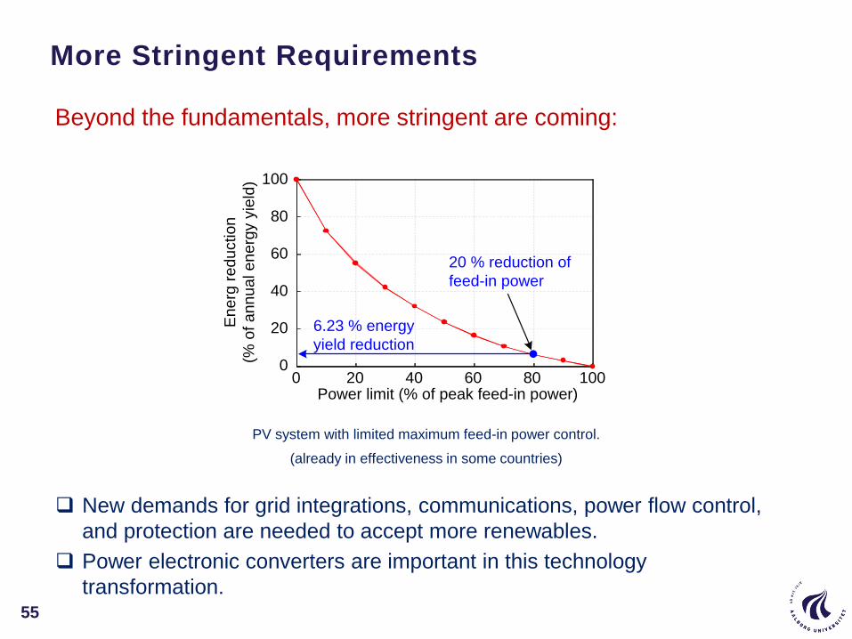
New demands for grid integrations, communications, power flow control,
and protection are needed to accept more renewables.
Power electronic converters are important in this technology
transformation.
PV system with limited maximum feed-in power control.
(already in effectiveness in some countries)
More Stringent Requirements
55
Beyond the fundamentals, more stringent are coming:
0 20 40 60 80 1000
20
40
60
80
100
Power limit (% of peak feed-in power)
En
erg
re
du
ctio
n
(% o
f a
nn
ua
l e
ne
rgy y
ield
)20 % reduction of
feed-in power
6.23 % energy
yield reduction
56
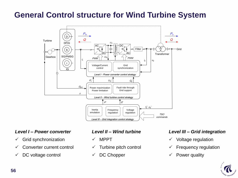
General Control structure for Wind Turbine System
Transformer
DFIG
SG/PMSG
IG
D
S
I
AC
DC
DC
AC
Filter Grid
Gearbox
Turbine
Level I - Power converter control strategy
Voltage/Current
control
Grid
synchronization
PWM PWM
Ps*
Pin
Udc*
Udc
Qg*
Level II – Wind turbine control strategy
Power maximization
Power limitation
Fault ride through
Grid support
θ
Ωgen
Level III – Grid integration control strategy
Inertia
emulation
P* Q*
Frequency
regulation
Voltage
regulation
fg* ,ug*
TSO commands
igis
Udc
Ch
op
pe
r
ug
Q
Po
Q
Level I – Power converter
Grid synchronization
Converter current control
DC voltage control
Level II – Wind turbine
MPPT
Turbine pitch control
DC Chopper
Level III – Grid integration
Voltage regulation
Frequency regulation
Power quality
57
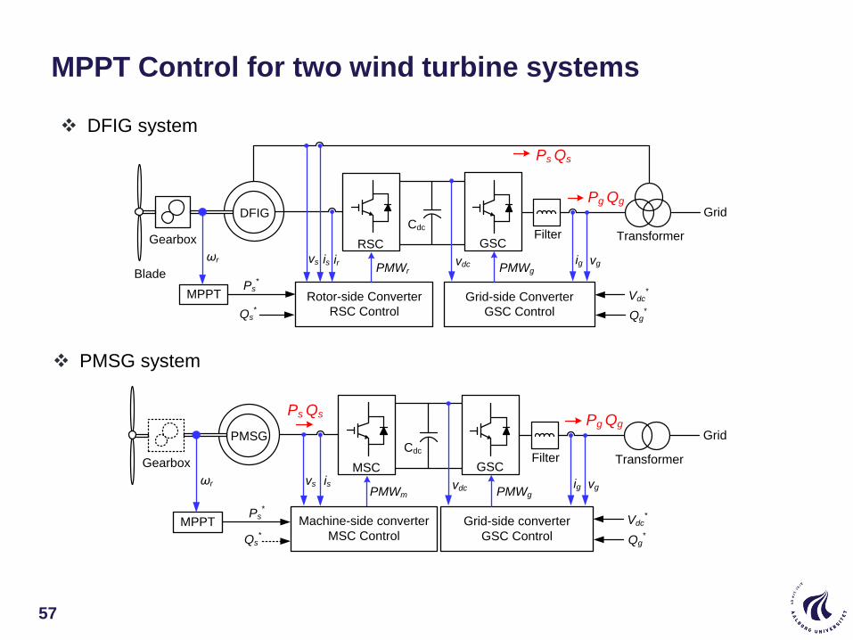
MPPT Control for two wind turbine systems
Blade
Gearbox
DFIG
RSC GSC
CdcFilter Transformer
Grid
Rotor-side Converter
RSC Control
Grid-side Converter
GSC Control
Pg Qg
Ps Qs
vdc
Ps*
Qs*
Vdc*
Qg*
MPPT
irvs isωr
PMWr PMWg
ig vg
Gearbox
PMSG
MSC GSC
CdcFilter Transformer
Grid
Machine-side converter
MSC Control
Grid-side converter
GSC Control
Pg Qg
Ps Qs
vdc
Ps* Vdc
*
Qg*
MPPT
isωr
PMWm PMWg
ig vgvs
Qs*
DFIG system
PMSG system

Summary
58
Cost of Energy more down incl low fai lure-rate
Reliabi l i ty important topic for future
Control of power electronic system emerging
Stabi l i ty in sol id state based power grid as wel l as conventional power system
More str ingent gr id codes wi l l st i l l be developed
Sti l l new technology in renewables (WBG etc..)
New power converters with new power devices
And much more..
Summary of presentation
59

Acknowledgment
60
Dr. Yongheng Yang, Dr. Xiongfei Wang and
Dr. Dao Zhou, Dr. Ke Ma
from Department of Energy Technology
Aalborg University
Look at
www.et.aau.dk
www.corpe.et.aau.dk
www.harmony.et.aau.dk


Thank you for your attention!
Aalborg University
Department of Energy Technology
Aalborg, Denmark
References
63
1. M. Liserre, R. Cardenas, M. Molinas, J. Rodriguez, ”Overview of Multi-MW wind turbines and wind parks”, IEEE Trans. on Industrial
Electronics, Vol. 58, No. 4, pp. 1081-1095, April 2011.
2. REN21 - Renewables 2014 Global Status Report, June, 2014. (Available: http://www.ren21.net)
3. Z. Chen, J.M. Guerrero, F. Blaabjerg, "A Review of the State of the Art of Power Electronics for Wind Turbines," IEEE Trans. on Power
Electronics, vol.24, No.8, pp.1859-1875, Aug 2009.
4. F. Blaabjerg, Z. Chen, S.B. Kjaer, “Power Electronics as Efficient Interface in Dispersed Power Generation Systems”, IEEE Trans. on
Power Electronics, Vol. 19, no. 4, pp. 1184-1194, 2004.
5. A.D. Hansen, F. Iov, F. Blaabjerg, L.H. Hansen, “Review of contemporary wind turbine concepts and their market penetration,” Journal of
Wind Engineering, Vol. 28, No. 3, pp. 247-263, 2004.
6. M.P. Kazmierkowski, R. Krishnan, F. Blaabjerg, Control in Power Electronics-Selected problems, Academic Press, 2002. ISBN 0-12-
402772-5.
7. F. Blaabjerg, M. Liserre, K. Ma, “Power Electronics Converters for Wind Turbine Systems,” IEEE Trans. on Industry Application, vol. 48,
no. 2, pp. 708-719, 2012.
8. F. Blaabjerg, K. Ma, “Future on power electronics for wind turbine systems,” IEEE Journal of Emerging and Selected Topics in Power
Electronics, vol. 1, no. 3, pp. 139-152, 2013.
9. H. Wang, M. Liserre, F. Blaabjerg, P. P. Rimmen, J. B. Jacobsen, T. Kvisgaard, J. Landkildehus, "Transitioning to physics-of-failure as a
reliability driver in power electronics," IEEE Journal of Emerging and Selected Topics in Power Electronics, Vol. 2, No. 1, pp.97-114, 2014.
10. H. Wang, M. Liserre, and F. Blaabjerg, “Toward reliable power electronics - challenges, design tools and opportunities,” IEEE Industrial
Electronics Magazine, vol.7, no. 2, pp. 17-26, Jun. 2013.
11. S. B. Kjaer, J. K. Pedersen, and F. Blaabjerg, “A review of single-phase grid connected inverters for photovoltaic modules,” IEEE Trans.
on Ind. Appl., vol. 41, no. 5, pp. 1292-1306, Sep. 2005.
12. K. Ma, F. Blaabjerg, and M. Liserre, “Thermal analysis of multilevel grid side converters for 10 MW wind turbines under low voltage ride
through”, IEEE Trans. Ind. Appl., vol. 49, no. 2, pp. 909-921, Mar./Apr. 2013.
13. K. Ma, M. Liserre, and F. Blaabjerg, “Reactive power influence on the thermal cycling of multi-MW wind power inverter”, IEEE Trans. on
Ind. Appl., vol. 49, no. 2, pp. 922-930, Mar./Apr. 2013.
14. C. Busca, R. Teodorescu, F. Blaabjerg, S. Munk-Nielsen, L. Helle, T. Abeyasekera, and P. Rodriguez, “An overview of the reliability
prediction related aspects of high power IGBTs in wind power applications,” Journal of Microelectronics Reliability, vol. 51, no. 9-11, pp.
1903-1907, 2011.
15. E. Koutroulis and F. Blaabjerg, “Design optimization of transformerless grid-connected PV inverters including reliability,” IEEE Trans. on
Power Electronics, vol. 28, no. 1, pp. 325-335, Jan. 2013.
16. K. B. Pedersen and K. Pedersen, “Bond wire lift-off in IGBT modules due to thermo-mechanical induced stress,” in Proc. of PEDG’ 2012,
pp. 519 - 526, 2012.

References
64
17. S. Yang, D. Xiang, A. Bryant, P. Mawby, L. Ran and P. Tavner, “Condition monitoring for device reliability in power electronic converters: a
review,” IEEE Trans. Power Electron., vol. 25, no. 11, pp. 2734-2752, Nov., 2010.
18. M. Pecht and J. Gu, “Physics-of-failure-based prognostics for electronic products,” Trans. of the Institute of Measurement and Control ,
vol. 31, no. 3-4, pp. 309-322, Mar./Apr., 2009.
19. Moore, L. M. and H. N. Post, “Five years of operating experience at a large, utility-scale photovoltaic generating plant,” Progress in
Photovoltaics: Research and Applications 16(3): 249-259, 2008.
20. Reliawind, Report on Wind Turbine Reliability Profiles – Field Data Reliability Analysis, 2011.
21. D. L. Blackburn, “Temperature measurements of semiconductor devices - a review,” in Proc. IEEE Semiconductor Thermal Measurement
and Management Symposium, pp. 70-80, 2004.
22. A. Bryant, S. Yang, P. Mawby, D. Xiang, Li Ran, P. Tavner, P. Palmer, "Investigation Into IGBT dV/dt During Turn-Off and Its Temperature
Dependence", IEEE Trans. Power Electron., vol.26, no.10, pp.3019-3031, Oct. 2011.
23. Z. Xu, D. Jiang, M. Li, P. Ning, F.F. Wang, Z. Liang, "Development of Si IGBT Phase-Leg Modules for Operation at 200 °C in Hybrid
Electric Vehicle Applications", IEEE Trans. Power Electron., vol.28, no.12, pp.5557-5567, Dec. 2013.
24. H. Chen, V. Pickert, D. J. Atkinson, and L. S. Pritchard, “On-line monitoring of the MOSFET device junction temperature by computation of
the threshold voltage,” in Proc. 3rd IET Int. Conf. Power Electron. Mach. Drives, Dublin, Ireland, Apr. 4–6, 2006, pp. 440–444.
25. D. Barlini, M. Ciappa, M. Mermet-Guyennet, and W. Fichtner, “Measurement of the transient junction temperature in MOSFET devices
under operating conditions,” Microelectron. Reliabil., vol. 47, pp. 1707–1712, 2007.
26. A. Isidori, F. M. Rossi, F. Blaabjerg, and K. Ma, "Thermal loading and reliability of 10 MW multilevel wind power converter at different wind
roughness classes", IEEE Trans. on Industry Applications, vol. 50, no. 1, pp. 484-494, 2014.
27. K. B. Pedersen, D. Benning, P. K. Kristensen, V.Popok, and K. Pedersen, "Interface structure and strength of ultrasonically wedge bonded
heavy aluminium wires in Si-based power modules," Journal of Materials Science: Materials in Electronics, Apr 2014.
28. K. Ma, A. S. Bahman, S. M. Beczkowski, F. Blaabjerg, “Complete Loss and Thermal Model of Power Semiconductors Including Device
Rating Information,” IEEE Trans. on Power Electronics, Vol. 30, No. 5, pp. 2556-2569, May 2015.
29. K. Ma, W. Chen, M. Liserre, F. Blaabjerg, “Power Controllability of Three-phase Converter with Unbalanced AC Source”, IEEE Trans. on
Power Electronics, Vol. 30, No. 3, pp. 1591-1604, Mar 2014.
30. K. Ma, M. Liserre, F. Blaabjerg, T. Kerekes, “Thermal Loading and Lifetime Estimation for Power Device Considering Mission Profiles in
Wind Power Converter,” IEEE Trans. on Power Electronics, Vol. 30, No. 2, pp. 590-602, 2015.
31. U. M. Choi, K. B. Lee, F. Blaabjerg, "Diagnosis and tolerant strategy of an open-switch fault for T-type three-level inverter systems," IEEE
Transactions on Industry Applications, vol. 50, no. 1, pp. 495-508, 2014.
32. Y. Yang, Huai Wang, Frede Blaabjerg, and Tamas Kerekes, “A hybrid power control concept for PV inverters with reduced thermal
loading,” IEEE Trans. Power Electron., Vol.29, No. 12, pp.6271-6275, 2014.
References
65
33. M. Liserre, F. Blaabjerg, and S. Hansen, “Design and Control of an LCL-Filter-Based Three-Phase Active Rectifier,” IEEE Trans. Ind.
Appl., vol. 41, no. 5, pp. 1281–1291, Sep. 2005.
34. L. Wei and R.A. Lukaszewski, “Optimization of the Main Inductor in a LCL Filter for Three Phase Active Rectifier”, 42nd IAS Annual
Meeting. Conference Record of the 2007 IEEE Industry Applications Conference, 2007, vol., no., pp.1816,1822, 23-27 Sept. 2007
35. J. Muhlethaler, M. Schweizer, R. Blattmann, J. W. Kolar, and A. Ecklebe, “Optimal Design of LCL Harmonic Filters for Three-Phase PFC
Rectifiers,” IEEE Trans. Power Electron., vol. 28, no. 7, pp. 3114–3125, Jul. 2013.
36. IEEE Application Guide for IEEE Std 1547™, IEEE Standard for Interconnecting Distributed Resources with Electric Power Systems
(2008)
37. “Generating plants connected to the medium voltage network - Guideline for generating plants connection to and parallel operation with
the medium voltage network”, BDEW Bundesverband der Energie- und Wasserwirtschaft e.V. Reinhardtstraße 32, 10117 Berlin (2008)
38. VDE-AR-N 4105: Generators connected to the low-voltage distribution network - Technical requirements for the connection to and parallel
operation with low-voltage distribution network (2010)
39. R. D. Middlebrook, “Design Techniques for Preventing Input-Filter Oscillations in Switched-Mode Regulators,” Proc. Power Convers.
Conf., 1978, pp. A3.1–A3.16.
40. Beres, R.N.; Xiongfei Wang; Blaabjerg, F.; Bak, C.L.; Liserre, M., "New optimal design method for trap damping sections in grid-connected
LCL filters," Energy Conversion Congress and Exposition (ECCE), 2014 IEEE , vol., no., pp.3620,3627, 14-18 Sept. 2014.
41. X. Wang, Y. W. Li, F. Blaabjerg, and P. C. Loh, “Virtual-impedance-based control for voltage-source and current-source converters," IEEE
Transactions on Power Electronics (Early Access Article, DOI: 10.1109/TPEL.2014.2382565).
42. X. Wang, F. Blaabjerg, and P. C. Loh, “Virtual RC damping of LCL-filtered voltage source converters with extended selective harmonic
compensation,” IEEE Transactions on Power Electronics (Early Access Article, DOI: 10.1109/TPEL.2014.2361853).
43. X. Wang, F. Blaabjerg, and P. C. Loh, “Grid-current-feedback active damping for LCL resonance in grid-connected voltage source
converters,” IEEE Transactions on Power Electronics (Early Access Article, DOI: 10.1109/TPEL.2015.2411851).
44. Y. Yang, H. Wang, and F. Blaabjerg, "Reduced junction temperature control during low-voltage ride-through for single-phase photovoltaic
inverters,“ IET Power Electronics, pp. 1-10, 2014.
45. D. Zhou, F. Blaabjerg, M. Lau, and M. Tonnes, "Thermal cycling overview of multi-megawatt two-level wind power converter at full grid
code operation", IEEJ Journal of Industry Applications, vol.2, no.4 pp.173–182, 2013.
46. K. B. Pedersen, P. K. Kristensen, V. Popok, and K. Pedersen, "Micro-sectioning approach for quality and reliability assessment of wire
bonding interfaces in IGBT modules", Microelectronics Reliability, Vol. 53, no. 9-11, pp. 1422–1426, Sep 2013.
47. K. Ma, F. Blaabjerg "Thermal optimized modulation method of three-level NPC inverter for 10 MW wind turbines under low voltage ride
through", IET Journal on Power Electronics, vol. 5, no. 6, pp. 920-927, Jul 2012.
48. R. Wu, F. Blaabjerg, H. Wang, and M. Liserre, "Overview of catastrophic failures of freewheeling diodes in power electronic circuits",
Microelectronics Reliability, Vol. 53, no. 9–11, Pages 1788–1792, Sep 2013.
References
66
48. F. Blaabjerg and K. Ma, "Wind Energy Systems," in Proceedings of the IEEE, vol. 105, no. 11, pp. 2116-2131, Nov. 2017.
doi: 10.1109/JPROC.2017.2695485
Open Access : URL: http://ieeexplore.ieee.org/stamp/stamp.jsp?tp=&arnumber=7927779&isnumber=8074545
49. F. Blaabjerg, Y. Yang, D. Yang and X. Wang, "Distributed Power-Generation Systems and Protection," in Proceedings of the IEEE,
vol. 105, no. 7, pp. 1311-1331, July 2017. doi: 10.1109/JPROC.2017.2696878
Open Access : URL: http://ieeexplore.ieee.org/stamp/stamp.jsp?tp=&arnumber=7926394&isnumber=7951054