KABA MAS Cencon 4 Software Reference Manual Table Of Contents
210
KABA MAS Cencon ® 4 Software Reference Manual Kaba Mas Welcome Kaba Mas, part of the world-wide Kaba group, is the world's leading manufacturer and supplier of high security, electronic safe locks. Its complete line of self- powered, battery, and mechanical locks meets virtually every safe lock requirement. Kaba Mas is dedicated to satisfying end-user needs for security, safety, and convenience. We welcome you to the world of Kaba Mas security and Cencon ® . Table Of Contents Chapter 1 - Introducing Cencon ® 1.1 The Cencon Program Package 1.2 System Overview 1.3 Personnel Classifications 1.3.1 Lock Users 1.3.1.1 First Line Maintenance (FLM) 1.3.1.2 Route Service Personnel (RSP) 1.3.1.3 Bank Personnel (B) 1.3.2 Software Users 1.3.2.1 Dispatcher 1.3.2.2 Supervisor 1.3.2.3 Special Supervisor 1.4 System Components 1.4.1 PC-Based Computer System 1.4.2 High Security Locks 1.4.2.1 Lock Operating Modes 1.4.2.2 Lock Storage Capacity 1.4.3 Smart Keys 1.4.3.1 Key Types 1.4.3.2 Smart Key Operation 1.4.3.3 Key Storage Capacity 1.5 System Data Definitions 1.6 System Precautions 1.7 System Processes 1.7.1 Activate Lock from Shelved Mode 1.7.2 FLM/Route Service Call 1.7.3 Route Call 1.7.4 Retrieve and Report on Audit Download from Lock 1.7.5 Shelve Lock 1.7.6 Add Bank Users To Lock After Activation 1.7.7 Delete Bank Users from Lock Chapter 2 - System Startup 2.1 Start the Cencon Program 2.2 Logon to the Cencon System 2.3 Main Window 2.4 Status Bar 2.5 Lock Operation in Shelved Mode 2.5.1 Open Lock in Shelved Mode 2.5.2 Change Shelved Mode Combination 2.6 Cencon Versus CenTran Considerations 2.7 Prepare System for Operation 2.7.1 Add Additional Users 2.7.2 Activate Locks Page 1 Document # 2071.127 Rev. A 12/09 Cencon 4 Reference Manual
Transcript of KABA MAS Cencon 4 Software Reference Manual Table Of Contents

KABA MAS
Cencon® 4 Software Reference Manual
Kaba Mas Welcome
Kaba Mas, part of the world-wide Kaba group, is the world's leading manufacturer and supplier of high security, electronic safe locks. Its complete line of self-powered, battery, and mechanical locks meets virtually every safe lock requirement. Kaba Mas is dedicated to satisfying end-user needs for security, safety, and convenience. We welcome you to the world of Kaba Mas security and Cencon®.
Table Of Contents
Chapter 1 - Introducing Cencon®
1.1 The Cencon Program Package
1.2 System Overview
1.3 Personnel Classifications
1.3.1 Lock Users 1.3.1.1 First Line Maintenance (FLM) 1.3.1.2 Route Service Personnel (RSP) 1.3.1.3 Bank Personnel (B) 1.3.2 Software Users 1.3.2.1 Dispatcher 1.3.2.2 Supervisor 1.3.2.3 Special Supervisor
1.4 System Components
1.4.1 PC-Based Computer System 1.4.2 High Security Locks
1.4.2.1 Lock Operating Modes 1.4.2.2 Lock Storage Capacity
1.4.3 Smart Keys 1.4.3.1 Key Types 1.4.3.2 Smart Key Operation 1.4.3.3 Key Storage Capacity
1.5 System Data Definitions
1.6 System Precautions
1.7 System Processes
1.7.1 Activate Lock from Shelved Mode 1.7.2 FLM/Route Service Call 1.7.3 Route Call 1.7.4 Retrieve and Report on Audit Download from Lock 1.7.5 Shelve Lock 1.7.6 Add Bank Users To Lock After Activation 1.7.7 Delete Bank Users from Lock
Chapter 2 - System Startup
2.1 Start the Cencon Program
2.2 Logon to the Cencon System
2.3 Main Window
2.4 Status Bar
2.5 Lock Operation in Shelved Mode
2.5.1 Open Lock in Shelved Mode 2.5.2 Change Shelved Mode Combination
2.6 Cencon Versus CenTran Considerations
2.7 Prepare System for Operation
2.7.1 Add Additional Users 2.7.2 Activate Locks
Page 1Document # 2071.127 Rev. A 12/09 Cencon 4 Reference Manual

2.8 Using Cencon 4
Chapter 3 - Cencon Software
3.0 Using Cencon Reports
3.1 Locks 3.1.1 Lock/Lock Operations Report
3.1.1.1 Activate Lock 3.1.1.2 Add Lock to a Collection 3.1.1.3 Add Lock to a Route 3.1.1.4 Add Users to a Bank Lock 3.1.1.5 Close a Lock 3.1.1.6 Close Locks With User Key 3.1.1.7 Close Locks Based on Verify of Open With Key 3.1.1.8 Delete Shelved Lock 3.1.1.9 Dispatch a Lock 3.1.1.10 Edit Lock Data 3.1.1.11 Export to File 3.1.1.12 Force Delete of Unshelved Lock 3.1.1.13 Import From File 3.1.1.14 Individual Lock Report 3.1.1.15 Manager Force Close w/o Seal 3.1.1.16 Map the Lock Location 3.1.1.17 Reassign 3.1.1.18 Reissue an Activate Key 3.1.1.19 Remove Users from a Bank Lock 3.1.1.20 Rename 3.1.1.21 Replace 3.1.1.22 Resynchronize the Cencon Database with Lock 3.1.1.23 Shelve Lock 3.1.1.24 Unassign an FLM Call 3.1.1.25 Undo Replace/Deleted Lock History Report 3.1.1.26 Update Activation of Gen2 Locks Activated in Compatibility Mode 3.1.1.27 Verify Shelve
3.1.2 Open Lock Log 3.1.3 Route Report
3.1.3.1 Route Lock Listing 3.1.4 Collections
3.1.4.1 Collection Lock Listing 3.1.5 Lock Open Alarm 3.1.6 Bank Branch Report 3.1.7 Lock Operations with Serial Connect
3.1.7.1 Activate FLM Mode 3.1.7.2 Shelve FLM Mode 3.1.7.3 Resynchronize Dispatching for FLM Mode 3.1.7.4 Set Access Between Single and Dual User for FLM Mode 3.1.7.5 Close Dispatch for FLM Mode 3.1.7.6 Activate Route Mode 3.1.7.7 Shelve Route Mode 3.1.7.8 Resynchronize Dispatching for Route Mode 3.1.7.9 Set Access Between Single and Dual User for Route Mode 3.1.7.10 Close Dispatch for Route Mode 3.1.7.11 Activate Bank Mode 3.1.7.12 Shelve Bank Mode 3.1.7.13 Resynchronize Users for Bank Mode 3.1.7.14 Set Access Between Single and Dual User for Bank Mode 3.1.7.15 Set Time Delay and Open Time Window for Bank Mode 3.1.7.16 View Bank Mode Users 3.1.7.17 Add Bank Mode Users 3.1.7.18 Delete Bank Mode Users 3.1.7.19 Set Lock Clock and Time Zone Daylight Savings Time Table 3.1.7.20 Create Lock Report 3.1.7.21 Create Lock Audit Report
3.2 Users
3.2.1 Add a User 3.2.2 Add a Windows Logon User 3.2.3 Change User Information 3.2.4 Change Information for Multiple Users 3.2.5 Rename a User 3.2.6 Delete a User 3.2.7 Display Open Locks for a User
3.3 Customers 3.4 History
3.4.1 Activity Log 3.4.2 Archived Activity Log 3.4.3 Lock Log History
Page 2Document # 2071.127 Rev. A 12/09 Cencon 4 Reference Manual

3.4.4 Archived Lock Log History 3.4.5 Deleted Lock History 3.4.6 User History 3.4.7 Archived User History 3.4.8 Archived Routes
3.5 Keys
3.5.1 Initialize Audit Download Key 3.5.2 Initialize Lock User Key Clock 3.5.3 Reinitialize User Key 3.5.4 Key report 3.5.5 Initialize a Lock Time Set Key 3.5.6 Create a Retrieve Bank Users Key (Gen2)
3.6 Authorization
3.6.1 Authorization Role Report 3.6.2 Authorization Definitions 3.6.3 Regions 3.6.4 Change Configuration Settings 3.6.5 Change Preferences 3.6.6 Security Hardware Report
Chapter 4 - Cencon Locks
4.1 Model Types and Operating Differences
4.1.1 Cencon Locks 4.1.2 Lock Operating Tips
4.2 Lock Operations
4.2.1 Open Lock In Shelved Mode 4.2.2 Change Shelved Mode Combination 4.2.3 Display Serial Number 4.2.4 FLM and Route Lock Activation 4.2.5 Open Lock - FLM or Route Mode 4.2.6 Open Lock - FLM or Route Dual Mode 4.2.7 View Last Close Seal Number 4.2.8 Display Audit Counts 4.2.9 Retrieve Audit Download From Lock 4.2.10 Shelve Lock (at Lock) 4.2.11 Bank Lock Activation 4.2.12 Bank Mode - Open Lock 4.2.13 Bank Mode - Add Users 4.2.14 Bank Mode - Remove Users 4.2.15 Bank Mode - Change User Combination 4.2.16 Set the Time on the Lock 4.2.17 Retrieve Bank Users from the Lock 4.2.18 Resynchronize the Database with Lock 4.2.19 Display Lock Level 4.2.20 Gen2 Lock Menu Prompts (70-79)
Appendix
Lock Error Codes Appendix A - Lock Keypad Commands Appendix B - Lock Displays and Prompts Appendix C - System Process Overview Appendix D - How to...
Activate Lock in FLM Mode (From Shelved Mode) Activate Lock in ROUTE Mode (From Shelved Mode) Activate Lock in BANK Mode (From Shelved Mode) Activate Lock in ROUTE Mode (Already in FLM Mode) Activate Lock in FLM Mode (Already in Route Mode) FLM/Route Service Call Pre-defined Routes Retrieve and Report on Audit Download Shelve Lock Add Bank Users To Lock After Activation Delete Bank Users from Lock
Appendix E - Determine Lock Level
Glossary
© 1996-2009 Kaba Mas LLC Document Number 2071.127 Rev. A 11/09 Cencon 4 Reference Manual
Page 3Document # 2071.127 Rev. A 12/09 Cencon 4 Reference Manual

Manual Conventions The Cencon Reference Manual is a comprehensive guide that contains information on the procedures you need to work with Cencon locks. This manual provides detailed information on Cencon features and step-by-step procedures for using the software. Some conventions that are followed are:
The Smart Keys needed for a particular operation will be shown beside the flowcharts that describe the operation. The screens shown in the manual that speak to inserting a key in a reader may depict either the use of the 2-port USB Key Box or the 4-port Key Reader in association with the PCI card. Input to the PC will be shown in bold type. The screen samples may not look exactly as they do on your system depending on which version of the Windows operating system you are using. Some samples in this document are from Windows XP and some are from Windows Vista. Highlighted items:
Note
Indicates a point to consider.
Important Note
Indicates information that is very important to know.
Helpful Hint
Indicates a technique or method that works well.
Caution
Indicates the need for care and caution to be observed during a procedure or process.
Warning
Indicates the possibility of loss of data or system integrity.
Before reading the Cencon Getting Started Guide, you should be familiar with basic Windows concepts and techniques. For detailed information, refer to your Windows documentation.
Page 4Document # 2071.127 Rev. A 12/09 Cencon 4 Reference Manual
Trademarks The following items are trademarks or registered trademarks of Kaba Mas in the United States and/or other countries.
Cencon Cencon S2000 PowerStar Technology Smart Key
Adobe and Adobe Reader are registered trademarks of Adobe Systems Incorporated in the United States and/or other countries.
iButton is a registered trademark of Dallas Semiconductor/Maxim.
Microsoft, Windows, Windows Server, Microsoft SQL Server, MapPoint, Word, and Excel are registered trademarks or trademarks of Microsoft Corporation in the United States and/or other countries.
Notice: The information in this manual is subject to change without notice and does not represent a commitment on the part of the Kaba Mas. Kaba Mas shall not be liable for technical or editorial errors or omissions contained herein; nor for incidental or consequential damages resulting from the furnishing, performance or use of this material.
Page 5Document # 2071.127 Rev. A 12/09 Cencon 4 Reference Manual

Cencon 4 Reference Manual
Chapter 1 - Introducing Cencon 4
1.1 The Cencon 4 Software Package
The following items are required to implement the Cencon 4 Software:
Cencon 4 Server License Kit: (Single Server Option - p/n 201190) Install CD (Includes Cencon 4 Software, Cencon Database Setup Utility, Software Reference Manual, and Adobe Reader) Cencon 4 Single Server License Certificate Software Getting Started Guide Quick Reference Cards (1 set) Cencon Software Maintenance & Support (CSM&S) Agreement Form 1 Change Key 7 Cencon Smart Keys:
2 red SA Keys 3 black Logon Keys 1 white Clock Set Key (for Gen2 locks) 1 grey ReSync Key (for Gen2 locks)
Mode Authorization License(s) (One or more)Bank Mode (p/n 201191). Includes 2 green B keys. FLM Mode (p/n 201192). Includes 2 blue F keys. Route Mode (p/n 201193). Includes 2 yellow R keys.
Cencon 4 orange Installation Key (p/n 202202) - Required to install Cencon 4 in conjunction with a USB Key Box on a new PC. Uniquely coded and tagged per company according to the mode licenses ordered. Packaged and shipped separately for security reasons. Cencon 4 Dispatch Kit: (p/n 201181)
Cencon USB Key Box - Uniquely coded per company. USB cable
An Enterprise / Multi-Server License Kit also is available - p/n 201194. This kit option includes all items in the Single Server Option and all 3 Mode Authorization Licenses shown above. A Cencon 4 Enterprise / Multi-Server License Certificate is provided instead of the Single Server License Certificate. The Installation Key and Dispatch Kits are still required for implementation and are still ordered separately.
If you are missing any of the above items, contact Kaba Mas Technical Support at 1 (800) 950-4744.
Optional Order Items:
Cencon 4 Software Maintenance & Support (CSM&S) Agreement Cencon On-Site Training for hands-on lock installation and complete lock and software operation. (2-day class required for new users.) CenTran 4 (XML) Software (p/n 201196) Cencon Key Maintenance Utility (KMU) Software Kit (p/n 201126)
(See www.KabaMas.com/cencon4 for more information.)
1.2 System Overview
Cencon 4 is a security program designed to control access to containers. It is capable of allowing one central location to monitor and control exactly who may access a particular lock and at what time (i.e., central control = Cencon.). Any number of locks may be controlled using Cencon, which is particularly well suited for companies that service Automated Teller Machines (ATMs). Through a combination of intelligent design and advanced technology, the Cencon system can achieve this control with no physical connection between the locks and the monitoring system.
Cencon 4 consists of three basic components:
1. PC-Based Computer Program 2. High-Security Locks 3. Smart Keys
The Cencon software controls access to Cencon locks in either or both of the following methods:
One Time Combination or "OTC" Method (FLM and Route Modes) Locks utilizing this access method will change their combination each time they are opened. The monitoring computer is able to anticipate what the next combination will be through a secure software algorithm that is built into both the locks and the central monitoring unit. It is impossible for either field service or monitoring personnel to know what combination will open a given safe next without first dispatching that combination to a particular key. A record of all security activity, including dates, times, and persons involved, is automatically maintained in the software, in the locks, and to a lesser degreein the keys themselves.
Repeating Access Code or "RAC" Method (Bank Mode) Locks utilizing this access method will open on a chosen combination for each key. The code chosen for a particular key can be reused to open the lock on a repeated basis, according to the access parameters established for this key, without requiring interaction with the software each time. Audit records of all lock activity, including dates, times and the persons involved, are automatically maintained in the locks and keys. This information may be reviewed through the Cencon computer program.
Access is further controlled by the advanced-design electronic keys known as Smart Keys. Once the lock is active in any of the modes, an opening can only occur with an OTC or RAC + the corresponding Smart Key. This dual token requirement of a physical device plus that user's known 6-digit number for opening the lock ensures security. If one of the two access tokens are compromised or lost, either the key or the combination, the lock remains secure. Audit information on locks, keys, and software may only be accessed by administrative personnel using the highest level of security safeguards. These audit records cannot be altered by anyone, not even those people who are granted the highest level of security in the system.
Page 6Document # 2071.127 Rev. A 12/09 Cencon 4 Reference Manual

It is important that you understand how the entire system operates, even though many of the operations will be carried out by other personnel. Before you start using the program, be sure to read the next few pages. They tell you what this package includes, the equipment you need to use the software, and they identify the components of the system and describe the people who will be working with them.
1.3 Personnel Classifications
There are two primary categories of people who can interact with the Cencon System: Lock Users, who open and close the lock in a particular mode, and Software Logon Users, who perform operations at the PC. For those who work with the PC system, authorization to system functions is defined through the Cencon PC software itself. The Personnel Classifications as designated in the system are as follows:
1.3.1 Lock Users
When a Lock User has a Smart Key programmed under their name, they typically keep that key with them at all times, and do not share the key with any other person. A particular Lock User's key can be initialized for any 1 of the 3 modes. The Lock User key cannot be used to logon to the Cencon software.
1.3.1.1 First Line Maintenance (FLM)
These are the field technicians whose duties include ATM repair work and lock installation. Due to the nature of their work, FLM techs are typically unaware of exactly where they may be dispatched on any given day. Each FLM tech carries a specially encoded Personal Identifier (Blue FLM Key) that, along with a dispatched combination, is required to access the lock.
1.3.1.2 Route Service Personnel (RSP)
Route personnel are field service people whose duties primarily consist of removing deposits from ATMs and replenishing currency for customer withdrawal. In some regions of the world, these users who drive Armored Cars / Armored Trucks are said to work for CIT (Cash In Transit) companies. Typically they service established routes with little variation, following a predetermined schedule. Route personnel carry specially encoded Personal Identifiers (Yellow Route Keys) that, along with a dispatched combination, are required to access the lock.
1.3.1.3 Bank Users
Bank Users are people whose duties include removing deposits from ATMs and replenishing currency for customer withdrawal. Typically, they service theATMs or safes only at the branch where they work. Bank Users carry specially encoded Smart Keys (green Bank keys), that identify them to the lock and are used along with a unique combination to access the safe. The access combination for a bank user is fixed until changed by that user.
1.3.2 Software Logon Users
The Cencon 4 software allows an unlimited number of unique Software Logon User types, called Roles, depending on what group of menu options the user should be given access to. Prior to Cencon 4 software, there have been only 3 different levels of access (Dispatcher, Supervisor, and Special Supervisor), which are described below as examples. The software has several other default Roles, such as Reporting and Bank Mode Only, for example. The use of some of these default roles allows functions that were previously unique to auxiliary programs used with the Cencon locks (CenBank, CenDemo, Key Maintenance Utility, Activation Only) to be incorporated into the Cencon software, yet controlled to certain personnel. Although the default Roles are not changeable, any type of Logon User can be uniquely customized by copying the default role and renaming it as a new role. Each Logon Users can either use an initialized black Smart Key + his or her chosen password to access the software, or access can be allowed when the user is logged into the Windows Operating System using Windows Authorization. At least one Special Supervisor logon key is required to be created in the system, though all other software logon users can choose to use Windows Authorization or a black Logon key. The software logon keys cannot be used at the Cencon lock to open it. Below, the 3 Logon User types that were used in previous Cencon versions are described, as an example of what each role may have with the software. For more information on creating and using Roles see sect. 3.6.1 on Authorization Definitions.
1.3.2.1 Dispatcher
The Dispatcher works directly with the Cencon software to issue lock combinations and direct the operations of the FLM and Route personnel (Bank users are not dispatched). Locks are opened and secured through a coordinated effort between the Dispatcher and an FLM or Route person. Each Dispatcher is permitted access to only certain sections of the Cencon program, depending on how the authorization levels are defined for certain activities.
1.3.2.2 Supervisor
The Supervisor directs the operations of the Dispatchers. The Supervisor normally has access to levels in the Cencon software that are not available to Dispatchers, including the viewing of activity records and the creation of service routes. Each Supervisor is permitted access to only certain sections of the Cencon software, depending on how the authorization levels are defined for certain activities.
1.3.2.3 Special Supervisor
The Special Supervisor always has unrestricted access to all levels of the Cencon program, so tight control should be taken over which personnel has been given this role or has access to this key. Since the system is required to have at least one Special Supervisor user, many customers will choose to lock this key in a secure location and not use it for daily operation, but instead only bring it out to log in during special situations.
1.4 System Components
The three basic components of the system are as follows:
1.4.1 PC-Based Computer System
The PC-Based Computer System is actually comprised of hardware and software components. Cencon 4 supports both the Cencon PCI Adapter Card and the Cencon Key Box. The Cencon PCI Adapter Card is installed into an open PCI adapter slot inside the PC. The Cencon Key Box is installed by attaching its cable to any USB port on your computer. These devices contain information which serves as unique identification for a specific company's system.
Note
Page 7Document # 2071.127 Rev. A 12/09 Cencon 4 Reference Manual

If a single company needs multiple stand-alone PC systems set up or multiple Cencon dispatching clients on the same network, multiple PCI Adapter Cards or Key Boxes can be issued to the same company with the same unique security code for that company burned into the device.
The Cencon PCI Adapter Card includes a second piece of hardware called the Smart Key Reader, consisting of 4 Smart Key ports. The key reader connects to the Cencon Adapter Card. Ports 0, 1 and 2 are configured as "read only" ports and are used for reading software logon keys only. Port 3 is used to create new keys and read audit keys. Because there are 2 versions of the Smart Key Reader, the location of Port 3 is described in 2 different ways: if the reader is the grey-colored, non-RoHS version (p/n 202019), Port 3 is the farthest from the key reader's cable. If the reader is the enclosed, black, RoHS-version (p/n 202212),Port 3 is the port on the far right-hand side.
Note
The non-RoHS version of the 4-port key reader (shown below on the left) is compatible with both older, plastic-fob keys and newer, metal fob keys. The RoHS version of the 4-port key reader (shown below on the right) is only compatible with the metal fob keys. The 2-port Cencon Key Box allows use of both metal and plastic-fob keys.
Shown above: P/N 202019. Non-RoHS-version Key Reader Shown Above: P/N 202212. RoHS-version Key Reader
The Cencon Key Box has two Smart Key ports, each having a green and a red status light. The blue LED in the middle is a power indicator when the unit is plugged in via the USB cable. A flashing green light indicates the port where the key needs to be inserted. Typically, the left-side port is used for reading an install key or a software logon key. The right-side port is used for creating or reading the audits from user keys or red SA keys. If there is an error reading the key, the red light is illuminated.
Shown above: P/N 202201. Cencon Key Box
FCC Notice
CENCON KEY BOX MODEL 202201
The Cencon Key Box is manufactured by Kaba Mas LLC, 749 W. Short Street, Lexington, KY, 40508, U.S.A., 859-253-4744, HTTP://www.kaba-mas.com. This device complies with Part 15 of the FCC Rules. Operation is subject to the following two conditions: (1) this device may not cause harmful interference, and (2) this device must accept any interference received, including interference that may cause undesired operation.
F
The software component is the PC-based Cencon 4 software. The software is designed to align itself with the internal software of the locks in generating unique One Time Combinations. Software functions also include the following:
User Management Lock Management Lock Activation/Shelving Reports and Auditing
In order to logon to the system, an authorized Logon User's Smart Key would be inserted into the Key Reader, and the authorized user's password must be entered. Instead of using a software logon key, a Windows user can be set up in the Cencon 4 software and be validated by Windows Authentication. Any user who is given Cencon software logon authority can logon and use the Cencon program.
1.4.2 High Security Locks
The Cencon locks are highly-secured, advanced-design locks. The original design was first developed for use on United States Government safes containing classified material. There are currently 2 different models of the Cencon lock series that will operate in conjunction with the Cencon 4 Software. They are as follows:
Page 8Document # 2071.127 Rev. A 12/09 Cencon 4 Reference Manual

Cencon Gen2 Cencon Gen1 (previously known simply as Cencon S2000)
Even though the locks are electromechanical, they require no wiring or batteries for opening the lock because they are self-powered. Power is generated by turning the dial knob on the lock to the left (counter-clockwise). After several turns of the knob, enough power is generated to allow the microprocessor in the lock to function. Combinations are then entered by pressing the numeric keys on the lock keypad, and a Smart Key is then presented to the lock's key reader. The software in the lock aligns itself with the PC software in generating unique One-Time-Combinations from the moment the lock is activated in FLM or Route mode.
Those users who are familiar with the operation of the Gen1 lock will notice few differences if operating the Gen2 lock as they did the Gen1 lock. However, many product enhancements exist with the Gen2 lock that are dependent on the type of PC equipment used to activate the lock.
See Chapter 4 - Cencon Locks for detailed information on the Cencon lock hardware.
1.4.2.1 Lock Operating Modes
Cencon locks may be set to operate in any of several different modes.
Note
It is important to note that any lock may be activated in two or more modes simultaneously (of the 3 modes not including shelved mode). These different modes in a lock can either all be controlled by the same company or by 2 or 3 different companies. Also note, once a certain company has activated one of the modes from their software, no other company can be in control of that particular mode until that mode's current controller deactivates (shelves) their control of that mode.
Shelved Mode
The Cencon lock opens on the fixed combination of 50-25-50 and does not require a key of any kind. This is the default factory mode that all new locks are in when they are shipped from Kaba Mas. It is also the mode that locks are placed in when they are completely shelved (i.e., all active modes) from service, i.e., they are not being used operationally as a security device.
Note
The Shelved Mode Combination can be changed to something other than 50-25-50. See "Change Shelved Mode Combination" in the System Start-Up section of this manual.
Route Mode
The Cencon lock requires the correct Route key and the correct OTC to open. After access is gained, the door closed, and the lock bolt extended, the Route key is presented to the lock to receive a Close Seal number. The Route mode user records and later relays the Close Seal to a Software Logon User. Multiple combinations may be issued to a Route Key as needed. In addition, the combinations to a predetermined list of locks (a route) may be issued to the Route person at the start of the work period. In this case the Close Seal numbers are automatically recorded in the Route person's Personal Identifier key when each lock is closed. At the end of the route the Close Seal numbers can be downloaded from the key into the Cencon computer or can be entered manually one by one, from a menu. If Two Person Integrity (TPI) is required, Route Mode may be set to require two different keys and combinations to open the lock (Route Mode with Dual Access).
FLM Mode
FLM Mode is similar to Route Mode, but typically each FLM user is only dispatched a single one-time-combination at a time. When the FLM user receives the Close Seal, a call is made to the Software Logon User, who enters the Close Seal into the Cencon software, freeing the FLM key to be dispatched to the next site which needs service. This mode is useful where the containers or locks may require periodic unscheduled maintenance. By default it is not possible to give more than one combination at a time to a particular FLM user, though this can be modified. This mode may also be set to require Two Person Integrity (FLM Mode with Dual Access).
Bank Mode
This is a special mode which allows the lock to be accessed by persons other than regular service personnel (typically bank employees) when the container is located at a bank. In Bank Mode, the lock will open repeatedly when using the confidential combination each unique to different authorized Bank user key, and will not issue a close seal number. Rather than receiving a close seal number, after the door is closed and the lock is secure, the Bank Mode User's key is presented to the lock to write a close audit record to the lock and the key. The bank personnel may change their combinations when desired by a simple procedure. Again, Two Person Integrity is an option (Bank Mode with Dual Access).
Bank locks may be set to operate with Time Delay when they are activated. If a lock is activated with Time Delay, the lock will only open after the Time Delay has expired and before the Window to Open (the time allowed after the Delay time to Open the lock before the lock resets) expires. When a lock is activated in Time Delay mode, the time delay applies to all Bank mode users.
1.4.2.2 Lock Storage Capacity
The maximum number of audit record lines that can be stored in a Cencon lock is around 500, depending on the access modes used, the type of lock and the type of audit records. After that limit is reached, the audit file will wrap around and begin overwriting the oldest records. Because the audit storage capacity in the Gen2 lock exceeds the storage capacity of the SA key, in order to view the oldest audit records, it may be necessary to directly connect the lock to a Cencon software PC using a special cable. However, typically an auditor is most concerned about the most recent set of records, so the SA key audit proves to be more than sufficient.
Note
An open and a corresponding close operation are recorded in 1 audit record line if performed by the same key, when used with a lock in Single Mode; therefore, the maximum number of opens and closes in the Cencon lock could be twice the number of audit lines; therefore it could be more than 1000 audit records.
1.4.3 Smart Keys
Page 9Document # 2071.127 Rev. A 12/09 Cencon 4 Reference Manual

Smart Keys are used by people who work with the Cencon system, whether it be at the PC using the software program or at the lock. A Smart Key is actually a Dallas Semiconductor electronic device imbedded in a plastic or metal fob. The keys are designed to be carried on a key ring like a traditional key. The keys are placed in the key reader attached to the PC and are initialized with unique data. The lock also has a key reader, where the Smart Key is presented, resulting in data verification and the writing of programming or audit records. These sophisticated electronic keys can securely hold large amounts of both temporary and permanent information.
1.4.3.1 Key Types
There are many key type designations, shown in the chart below, which can be classified into 3 different categories: Lock Users, Software Users, or Data Transfer Keys.
The Lock User and Software User keys are sometimes known as Personal Identifier (PI) Keys. They are called Personal Identifier Keys because they uniquely identify the owner of the key once they have been added to the system. The PI keys are meant to be programmed to 1 individual for audit purposes and are not meant to be shared, or else security will be compromised.
The Data Transfer keys are programmed at the Cencon software to be used at the lock for a particular function, and then brought back to the Cencon software. Although the Data Transfer keys are usually loaned to a particular employee who already has a Lock User key, the Data Transfer keys are not programmed with any restriction that requires any certain Lock User to only be able to use them.
*Note - Old vs. New Lock User Button Types (DS1994 / DS1427 vs. DS1963S)
The button types used in the historic F, R, and B keys (DS1994 + DS1427) are being phased out due to aging irreplaceable equipment by the manufacturer. Kaba Mas will continue to sell this version of the keys for several more years. This version of the F, R, and B keys will continue to work on both Gen1 and Gen2 locks.
Future Availability: The DS1963S buttons will use the same colors as the historic F, R, and B keys, but can be differentiated by the shape of the key fob. They are not supported on Gen 1 locks or in Gen 2 locks activated in Compatibility Mode. The hour-glass shaped F, R, and B keys which use DS1963S buttons will only work with Gen2 locks activated in Full Gen2 Mode (activated with a USB Key Box).
Customers should tag and label the keys with the type of key and the user name that is defined in the system.
Lock User Keys:
The Lock User keys maintain internal audit trails which record opening and closing times. The DS1994 and DS1427 keys contain internal clocks which are set at the PC when the key is initialized for a specific user and when the Initialize Lock User Key Clock operation is performed. The DS1963 key audits are time-stamped using the clock found in the Gen2 lock.
FLM (F) Key
This blue PI key is used by FLMs by touching it to the key reader on the side of a Cencon lock. This key lets the lock know that the FLM is authorized to open that particular lock. It is also used to get audit counts from locks in FLM Mode. A report may be generated from this key at the PC system, showing the user's activity.
Route (R) Key
The yellow Route PI key is used very much like an FLM PI, but by Route Personnel. It uses the same electronic device used in the F key and therefore has the same characteristics and capabilities. A report may be generated from this key just the same as with the F key.
Bank (B) Key
The green (teal) Bank PI key is used very much like the FLM and Route keys except that the combination does not change between uses. A report may be generated from this key just the same as with the F key.
Software User Keys: Logon (L) Key
This black PI key is used by an employee that has been given access to the Cencon software. The type of access the logon key has been assigned will
Kaba Part Abbreviation Description Category Compatibility Color Shape Button Type202020 F FLM mode personnel Lock User Gen1 & Gen2 Blue teardrop (bent) DS1994202022 R Route mode personnel Lock User Gen1 & Gen2 Yellow teardrop (bent) DS1994
202023 B Bank mode personnel Lock User Gen1 & Gen2Green (Teal) teardrop (bent) DS1427
202024 LLogon to Cencon (Ex: D, S, SS) Software User
all Cencon S/W versions Black teardrop (bent) DS1991
212030 A Additional logon to KMU Software User KMU software only Orange teardrop (bent) DS1429 202021 SA Supervisor Audit Data Transfer Gen1 & Gen2 Red teardrop (bent) DS1996
202202 IS Install Cencon 4 Software Data Transfer Cencon 4 & above only
Orange hourglass (flat) DS1963S
202226 CS Clock Set Data Transfer Gen2 + Cencon 4 only White hourglass (flat) DS1922L202224 RS Re-Sync Data Transfer Gen2 + Cencon 4 only Dark Grey hourglass (flat) DS1963S 202220 F* FLM mode personnel Lock User Gen2 + Cencon 4 only Blue hourglass (flat) DS1963S202222 R* Route mode personnel Lock User Gen2 + Cencon 4 only Yellow hourglass (flat) DS1963S202223 B* Bank mode personnel Lock User Gen2 + Cencon 4 only Green hourglass (flat) DS1963S
Page 10Document # 2071.127 Rev. A 12/09 Cencon 4 Reference Manual

depend on the authorization role given when it was initialized (Dispatcher, Supervisor, Bank Mode Only, etc.) This key must be inserted into the key reader at the Cencon PC client when the user is logging on to Cencon and may then be removed and secured. Users should log off during breaks and at the end of a work shift.
Note
In the Cencon 4 software, the logon key is only accessed during the logon process. To change the effective user, and/or region, one must log out of Cencon and log back in with the desired key in the reader.
Data Transfer Keys:
Supervisor Audit (SA) Key
The red Supervisor Audit key is initialized at the PC key reader with the information needed to take it into the field to activate locks, shelve locks, or audit a lock. A single SA key can be initialized to activate or shelve multiple locks. This key can also be used to retrieve audit records from locks, and to add and delete bank mode users from a lock. For Gen2 locks only, an SA key can be programmed to retrieve the list of bank users from a bank mode lock.
Install (IS) Key
The orange Install key is initialized by Kaba Mas with the information needed to identify the Cencon Customer and install Cencon on a computer. This unique key must be used during installations of Cencon 4 to allow a particular company's Key Box to be used on a particular PC. The company's unique security number programmed to the install key must also match the security number for that company programmed to all of their Key Boxes and PCI cards. The key and the tag attached to the key should be kept in a secure location after the installation process.
Clock Set (CS) Key
The white Clock Set key is initialized by Cencon 4 software and used to set the clock and the daylight savings time information in Gen2 locks.
Lock ReSynchronization (RS) Key
The dark grey Lock ReSync key is initialized by Cencon 4 software and used to resynchronize the data in the Cencon database with the data in a Gen2 lock.
1.4.3.2 Smart Key Operation
The Smart Keys used with Cencon provide a two-tiered approach to system security by requiring not only that anyone who opens a lock, or accesses system data on the computer has a key, but also that it is the correct type and has been properly initialized. For Lock User keys, the key is also used to provide a communications link between the central computer and the locks it controls. An audit trail of the Lock User key's activity is maintained inside the key itself.
The device that makes this possible is the Dallas Semiconductor iButton™ electronic device. This is the device in the key that looks like a watch battery. Yet, it is much more. Inside the stainless steel container there is a battery, and, in some models, a quartz crystal driven timekeeping system that provides real-time clock capabilities. Each key also has a unique serial number built into it that can be read but never changed. For more detailed information about the iButton™, you can refer to the Dallas Semiconductor web site at www.maxim-ic.com.
The iButton™ device is mounted in a convenient plastic or metal housing that allows it to be carried on a key chain and also provides a handle for inserting the key into the key reader at the PC or on the lock. When the key is inserted into the key reader, electrical connection is established between the internal electronics and the lock. Once the data communication is established, the lock can read data from the key and save the time and other data into the key's memory. Which function the lock performs depends partially on which type of key is inserted and what mode the lock is in.
The memory in the key is used to transfer data from the computer to the lock and from the lock to the computer. The data read from the key by the lock is used to assure that the key's user is authorized to perform the requested function. Data is also stored in the key by the lock, such as the data from a lock audit download to an SA key. The key can then be read by the computer to provide a record of lock activity.
Another function of some of the keys is to provide a time stamped record of activities performed at the lock. For Gen1 locks, this is done by using the real-time clock capability of the key. Power for the key is from a lithium battery inside the key which can last up to ten years, depending on frequency of use and temperature variations. The battery is used to run the quartz crystal that provides the time base for the real-time clock but is not necessary for the memory functions. For Gen2 locks, the audit times and dates recorded to the lock and the keys come from the real-time clock in the lock, no matter what type of Lock User Key is used.
1.4.3.3 Key Storage Capacity
The Smart Keys used with Cencon also have limits on the number of records that can be stored in them. The maximum for each key is determined by the amount of memory in the key and the type of records stored. For example, the SA key can hold several hundred audit record lines, depending on how the lock was configured and the types of audits. (Note that the SA key can only hold the records for a single lock at a time). Lock User Keys will also hold between 15-30 audit record lines of information, depending on the access modes used, the type of lock and the type of audit records. After that limit is reached, the audit file will wrap around and begin overwriting the oldest records. Because each audit record line could contain both an open time and a close time if opened by the same key in single access mode, this equates to a maximum number of open and close records on a Lock User Key between 30-60 event records.
1.5 System Data Definitions
It is very important to understand the definition and usage of the data fields that are set in the Cencon PC software.
Note
Page 11Document # 2071.127 Rev. A 12/09 Cencon 4 Reference Manual

Date and Time Values
All dates displayed by the Cencon software are in the international standard format defined by ISO (ISO 8601).
Dates in this standard appear as follows: YYYY-MM-DD, where:
YYYY is the year [all the digits, i.e. 2012] MM is the month [01 (January) to 12 (December)] DD is the day [01 to 31].
For example, "29th of December 2009", in this international format is displayed as 2009-12-29.
The international standard notation for the time of day is hh:mm:ss where:
hh is the number of complete hours that have passed since midnight (00-23) mm is the number of complete minutes that have passed since the start of the hour (00-59) ss is the number of complete seconds since the start of the minute (00-59).
Midnight is represented by hh = "00".
Region
Region Data Access Control is a security option available within the Cencon software. Region Control is active when the checkbox displayed in the 'Change Configuration Settings' screen has been selected. If the Region Control option is turned Off, then the Region field is optional data for locks, users, and routes, and lock users are not restricted from being dispatched to certain locks based on the region, nor are Logon users restricted to what data they can see and manage based on the region. If Region Control is turned On, it gives Cencon the ability to group users, locks, and routes into specific regions and then limit each user's access to only the users, locks and routes in their region. Every Cencon logon user would be assigned to either a Global region or Local region. The classification of a Global region or Local region does not alter the restriction that a lock user assigned to a region can never be dispatched to a lock assigned to a different region. Assignment to a Global region vs. a Local region affects what a Cencon logon user (i.e. Dispatcher, Supervisor, etc.) can see and manage within the Cencon System. Special Supervisors are always assigned to a global region, by default.
Local region logon users Only have access to users, locks and routes in their own region. Do not have access to the region maintenance functions. May only create users, locks, and routes in their region. Can never dispatch a lock user to a lock in a different region.
Global region logon users Have access to all users, locks and routes, regardless of the region. Can never dispatch or reassign a lock user in 1 local region to a lock in a different region. Even lock user that is designated as Global can only be dispatched to locks that are designated as Global, not to locks with any local region. A global logon user is required to select the region to be used for activating or shelving locks before the locks to be activated or shelved are specified. FLM/RSPs to be used in the activate or shelve process must belong to the region selected by the dispatcher. A global logon user can change the region assigned to any user, lock, or route.
Database Preparation A common example of how region control can be used is that several existing regional databases within a particular company, all using the same PCI security code and Company ID, could be merged to form a single common database accessed by all users. The logon users at the various branches could be given local regional access, which would allow them to only see, manage, and add locks and users within their local region. TheIT managers would only have 1 central database to manage and support rather than multiple regional databases. Customers should contact Kaba Mas for assistance or advice on this process.
See Region Maintenance for more information on Region Control.
Company ID
The value entered for this field is set during the original software installation and can be any four-digit number you wish to identify your company. You should choose a number that is, in some way, meaningful to your company, and yet complex. Once this ID is set, you cannot change it. You should also record this number, and keep it in a secure location, since the number is no longer visible during or after logging in to the Cencon 4 software. If you are a branch of a larger company, or you are upgrading, you must enter the Company ID that has already been chosen for your company. If you are planning to activate locks from Cencon running on a networked PC, the Company ID must be the same on all systems involved in the process.
Customer Names
The Customer Name is a unique identifier that allows optional grouping of locks, users, and routes (usually for specific customers). This is especially useful when a single company is servicing locks for multiple customers. Customer Names can also provide a way of grouping Locks that have similar characteristics, such as belonging to a branch bank, or being located in a certain geographical area, or any grouping that the organization controlling the locks finds useful.
Group I.D.
Group I.D. is a six character identification for a group of locks. The Lock Groups Feature allows a lock to be assigned to a group that may only be servicedby FLMs and RSPs who are assigned to service that same group or all groups. A group is defined by a six character item in the Lock definition record and may consist of two, four, or six non-blank alphanumeric characters. A Lock may be assigned to a group when it is activated or by using the "Edit Lock Data" process. An FLM or RSP User I.D. may be assigned to a group when the user is added to the Cencon System or by using the "Change User Information" process.
Lock Groups are active when the checkbox displayed in the 'Change Configuration Settings' screen has been selected. Otherwise, data in the Lock Group field is optional.
An FLM or RSP may be dispatched to service a Lock if any of the following conditions are true:
The FLM or RSP has no group assignment.
Page 12Document # 2071.127 Rev. A 12/09 Cencon 4 Reference Manual

The Lock has no group assignment. The FLM or RSP and the Lock have group assignments and the assignments match exactly. The FLM or RSP Group I.D. is a subset of the Lock Group I.D.
Example: If an FLM is assigned a Group I.D. of 'AB', then it may service any lock that contains 'AB' as the first two characters of the group (for instance, the key could be dispatched to locks in group AB11 and AB22).
Note
When developing Group I.D.s and deciding on the Group I.D. for a particular lock, keep in mind that you can create subgroups within groups by using each 2 characters of the six-character field.
Example: Using a Group I.D. of 112233, you can create other Group I.D.s that also begin with the characters "11". Then, for a particular FLM, you can grant security access for all locks that have a Group I.D. that begins with the characters "11" by specifying a partial Group of "11" as the user's Group when you add a new user to the system.
Activate, Shelve and Replace Lock processes are not affected by Lock Group definitions.
Existing restrictions such as Schedule Time Windows and security checks are not affected by Group I.D.
1.6 System Precautions
Although the Cencon locks, the PCI cards, and the Cencon Key Box are designed to be easy to install and use, there are a few areas where caution needs to be exercised.
Caution
Electrostatic Discharge (ESD): Kaba Mas locks and PCI cards are well protected from ESD damage once they are installed, but can be damaged during the installation process if proper precautions are not observed. When handling the locks, follow these precautions:
Everything on and around work stations which might come into contact with ESD sensitive devices should be conductive and connected to earth ground through a resistor. The purpose of the resistor is to prevent electrical shock in case something should come in contact with a voltage source. The technicians installing the locks and PCI cards should also be "grounded." Technicians can wear conductive wrist bands with "alligator" clips connected to a convenient source for earth ground. The stainless steel plate on the wrist band should directly contact the technician's skin. When handling the back covers of Cencon locks and the PCI cards, do not directly touch the electronic components. Handle the covers by the edges, being careful not to touch the connectors. Eliminate the use of all unnecessary plastics, paper, and synthetics during installation. In addition, all locks and PCI cards are shipped with static shielding material (that do not generate static charges) and an antistatic sleeve covering the cable end. Do not install the back cover assembly until the flex cable connectors have been seated into their proper positions. Touching these cables transmits ESD from the technician's body through the cables to the electronic components of the back cover.
The Cencon Key Box
Operators may become statically charged in a normal working environment. Inserting keys or just touching the Key Readers on the Cencon Key Box may cause the computer’s Operating System (OS) to disconnect from the Cencon Key Box. In this instance, un-plug and re-plug the USB cable between the computer and the Cencon Key Box. In addition, an ESD strike may cause the Cencon 4 software to malfunction. In this case, re-start the Cencon 4 software and continue your operation.
1.7 System Processes
There are numerous system processes that involve integrating activity at the PC software with activity at the lock. It is important that these processes be completed in their entirety. The following is an overview of each of these processes with links to the detailed "How To..." section of this document.
1.7.1 Activate Lock from Shelved Mode A lock's default mode is Shelved Mode. A key must first be programmed for "activation" and then used at the lock before it can become a functional security device. From the Cencon software a lock can be activated in FLM Mode, Route Mode, Bank Mode, or any combination of these modes at the same time. The lock activation key (SA key) must first be programmed at the PC. Depending on which mode(s) are to be activated, the appropriate lock user key(s) are also prepared at the PC. Then, these keys are taken to the lock, along with a standard Cencon change key, in order to perform the activation procedure.
Details: Activate Lock in FLM Mode Activate Lock in Route Mode Activate Lock in Bank Mode Activate Lock in Route Mode from FLM Mode Activate Lock in FLM Mode from Route Mode
1.7.2 FLM/Route Service Call A lock will need to be opened periodically by either an FLM Technician or a Route Person. First a combination must be dispatched from the Cencon PC System. The FLM or Route Person then takes the combination that was issued and their respective Personal Identifier Key to the lock. The lock is opened with the dispatched FLM or Route service combination, and the necessary service operations are performed. The lock is then closed and the Personal Identifier Key (F or R) is used to retrieve the Close Seal. The Close Seal is reported to the Cencon dispatcher to close the call.
Details:
Page 13Document # 2071.127 Rev. A 12/09 Cencon 4 Reference Manual

FLM/Route Service Call
1.7.3 Route Call When a Route is dispatched from the Cencon PC System, it may involve one or multiple locks and one or multiple visits to each lock. This involves using the Cencon software to first define a multi-lock route before the combinations for this route are ever dispatched. Once the combinations are issued, the Route Person takes those route combinations and the R Key to each of the respective locks in the route. A route may occur in a single day or can be spread over multiple days. Each lock is opened with the dispatched Route combination for that lock and the specific sequence of visitation to the lock. A single lock may be visited up to 3 times within a single route. Once the lock is open, the appropriate route activities are performed. The R key is then used to close the lock and obtain the close seal which is returned to the Cencon dispatcher to close the call. The close seal can be called in to the Dispatch center at the time a Lock is closed as with a single service call, or the Route person can wait until the route has been completed and can then turn in the R key to close the calls in the PC System with the key.
Details: Route Call
1.7.4 Retrieve and Report on Audit Download from Lock The audit records recorded in a lock may be written to an SA key which is then taken to the PC to be printed. The procedure is to use the Cencon software to initialize an SA key for the retrieval of the audit data. The key is then taken to the lock. The lock is powered up and the retrieve audit command is entered. The key is held to the key reader on the lock while the data is written into its memory. The key with the data now written in it is taken to the PC where the data is read and a report is either printed or displayed. No PI key is required and the lock does not have to be opened.
Details: Retrieve and Report on Audit Download from Lock
1.7.5 Shelve Lock A lock may be temporarily removed from active service by shelving it. This involves using the Cencon software to prepare an SA for the shelving and performing the shelve operation at the lock. The process is slightly different depending on the lock mode. Note that a lock can be shelved in multiple modes (FLM, Route, Bank) with the same key at the same time if the modes were activated on the same Cencon database.
Details: Shelve Lock in FLM Mode
1.7.6 Add Bank User(s) To Lock After Activation When a bank mode lock is activated, the users that are selected when the SA was programmed are added to the lock's authorization table. Additional users can be added at any time. The new users must first be added to Cencon if they do not already exist. Then the users must be given authorization to access the lock and the SA key is prepared at the PC to transfer the user data to the lock. This activity must be performed by an authorized Bank mode lock user because it requires that the lock be opened. This user must then take the SA Key and Change Key to the lock where users are going to be added.
Details: Add Bank Users To Lock After Activation
1.7.7 Delete Bank User(s) from Lock Part of maintaining the security of Bank Mode means deleting users from the lock when they no longer need access. This operation involves initializing an SA key with the information necessary to delete the users from the lock. A Bank mode lock user with opening authorization must then take the SA Key and Change Key to the lock where user(s) are going to be deleted, and open the lock to perform the Delete Users operation.
Details: Delete Bank Users from Lock
Page 14Document # 2071.127 Rev. A 12/09 Cencon 4 Reference Manual

Chapter 2 - System Startup
2.1 Start the Cencon Program
The contents of this chapter are intended to assist you with System Start-up. Before you proceed, you should already have completed the activities found in the Cencon 4 Software Getting Started Guide (P/N 2058.075).
To start the Cencon program:
1. Select the Start icon from the Windows task bar. 2. Select the Programs menu item. 3. Select the Cencon menu item.
4. Select the Cencon 4.0 icon.
When you start the Cencon system, you may need to identify the database connection, depending on how the Cencon system configuration data is set.
5. If you see the following window, you have not selected a Cencon database:
Select "Database Connection Settings" to access the dialogs which allow you to identify the appropriate Cencon database.
If the input field for "Set this ODBC Connection as fixed database logon" is checked, Cencon remembers the database connection for the next time the program is loaded.
Select the button labeled "Select ODBC Data Source" to select the ODBC connection for the database to be used with the Cencon system.
Select the Catalog tab if you need to modify the database catalog name:
Page 15Document # 2071.127 Rev. A 12/09 Cencon 4 Reference Manual

Select the Schema tab if you need to modify the database schema:
If using the default schema of "dbo" with one of the versions of Microsoft SQL Server, (i.e. Microsoft SQL Server 2000, 2005, 2005 Express, etc) you do not have to update the schema name.
6. The following window is displayed when a database is successfully identified:
Page 16Document # 2071.127 Rev. A 12/09 Cencon 4 Reference Manual

Continue with "Logon to the Cencon System". You can also refer to the "Cencon 4 Getting Started Guide" for additional details.
Page 17Document # 2071.127 Rev. A 12/09 Cencon 4 Reference Manual

2.2 Logon to the Cencon System
The Cencon startup window controls access to configuration settings and logon:
See the Cencon Getting Started Guide for details on the "Cencon PCIO Card and Key Box Settings" and the "Database Connection Settings" functions.
Cencon allows a user to logon using either an authorized black Software Logon User key (such as Dispatcher, Special Supervisor, etc.). Additionally, a user may logon using their authorized Windows logon password.
1. To logon using a key, select Logon to Cencon with Key. Insert the black key in the proper port. If the key is recognized as valid, enter the password as requested:
Remember that this field is case sensitive and recognizes spaces as well as characters.
Note
You cannot logon to the system using a nickname, or a user ID. You must use the password specified for the key in the key reader. The key in the key reader identifies the user trying to log onto the Cencon System.
Hint
If a window is displayed indicating that the User ID doesn't pass authority check, first check to make sure that the appropriate key is in the reader and that the reader is properly connected.
2. To logon using a Windows Logon password, select Logon to Cencon with Windows Logon. Note that the Windows user name must already be set up as a user within Cencon (in the same manner as a user key).
Caution
The Cencon logon key is only accessed during the logon process. Once you are logged on, you should remove your key from the key reader and secure the key. You should also be sure to close Cencon when you leave the PC, as recommended by the following message:
After a successful logon, the Cencon Main Menu window is displayed. Some of the items may not be displayed on your system depending on your user authority settings.
Page 18Document # 2071.127 Rev. A 12/09 Cencon 4 Reference Manual

2.3 Main Window
The Main Window displays only those functions authorized for the current user. Related functions are grouped as follows.
Accelerator Keys
The following accelerator keys are programmed to access functions on the main window: F1 = Help Ctrl + A = Activate Locks Ctrl + D = Dispatch Locks Ctrl + K = Close Locks with Key Ctrl + L = Lock Operations Ctrl + R = Route Report Ctrl + S = Close Lock Ctrl + U = Add User Keys Ctrl + W = Add Windows Logon User
Lock operations:
Note
The most commonly used functions (Dispatch, Reassign, and Close) are available via 2 methods. Both (A) by direct access from clicking the icons on the main menu, which requires typing in the lock name or lock serial number, and (B) from within the Lock reports, which allows you to search for the specific lock, right click the line of that lock, and choose from basic operations to perform on that lock. Within this document, most of these basic functions are shown accessed via the icon on the main menu; however, depending on your operational use of the software, you may discover that leaving the Lock Operations report open, searching for the locks from there, and performing all dispatching and closing by right-clicks improves your personal daily efficiency.
User operations:
History operations:
Key operations:
Page 19Document # 2071.127 Rev. A 12/09 Cencon 4 Reference Manual

System operations:
These functions are access options pertaining to functions for customizing and maintaining your Cencon system.
Note
If any operational item is not displayed or is displayed in gray (disabled), that item is not available to the current user (usually because they are not authorized to access the function). Security of the Cencon system is based on the key in the key reader, the function being requested, and the authorization role assigned to the function by the manager who installed or customized your software. Refer to the Authorization Functions chapter for more detailed information.
2.4 Status Bar
The Status Bar is located at the bottom of the Cencon Main Menu screen. Prior to logon, this area displays the Cencon software version information. After logon, this bar displays the name of current logged on user, their assigned role, and region information (if region control is active).
Page 20Document # 2071.127 Rev. A 12/09 Cencon 4 Reference Manual

2.5 Lock Operation in Shelved Mode
Note
If you are operating a Cencon lock and -dL appears on the display during an operation, it indicates that you should dial Left (Counter Clockwise). The purpose is both to give the lock additional power and to ensure the lock bolt is fully extended. CW= Clockwise; CCW = Counter Clockwise
2.5.1 Open Lock in Shelved Mode
Each Cencon Lock is shipped from the factory in Shelved Mode. The One Time Combination feature which requires a Smart Key is not available when the lock is shelved. Instead, the Shelved Mode combination is used to open the lock without any Smart Key. The default Factory Combination is set to 50-25-50. Practice opening the lock in shelved mode with the default factory combination until you are comfortable with its operation. The default combination may be changed, in which case the new combination would be used to open the lock while in Shelved Mode. The correct opening procedure for a shelved lock is:
1. Power Lock → EC Turn the dial to the left (CCW) until the letters EC (Enter Combination) appear in the display window.
2. EC → Enter Shelved Mode Combination → OPr Enter the current Shelved Mode combination, whether it be the Factory Combination of 50-25-50 or a newly set Shelved Mode combination, by sequentially pressing those digits on the lock keypad. The LCD will display the numbers as the combination is entered. When the combination has been correctly entered, OPr will be displayed, meaning "OPen right".
3. Opr → Retract Bolt Turn the dial to the right (CW) to retract the bolt.
4. Open Door
5. Close Door
6. Extend Bolt Turn the dial a minimum of one complete rotation to the left (CCW) to extend the bolt.
Note
After opening and closing any lock, you should always check to ensure that the lock is physically relocked (i.e., bolt fully extended and locked in place) by turning the dial to the right. If the bolt does not retract, you can be assured the lock is secured.
Helpful Hint
At any point while entering the combination during an opening sequence, if you notice that an incorrect number was pressed on the keypad, you may clear the entire operation and start again by pressing the star ( * ) key. This allows you to return to the EC prompt without getting a wrong try error (lightning bolt).
Caution - Lock Out (LCO)
When the combination is incorrectly entered, a lightning bolt error will flash on the display (with no other numbers following it). To clear this error and start again, press and hold the star ( * ) key. Even in Shelved Mode, it is important to avoid getting 5 wrong combination attempts in a row without a successful opening in between because the lock will be put into Lock-Out condition, displaying, "LCO." Clearing the LCO condition in Shelved Mode requires waiting 5 minutes and then entering the correct combination.
Gen2 Locks If there is a problem with the battery in the Gen2 lock when a lockout occurs, the lock must have power for the full timeout period. The display will alternately flash -dL and LCO to indicate this.
2.5.2 Change Shelved Mode Combination
Required Items: Change Key
For Cencon Locks with a code level of 71, or greater, you may change the Shelved Mode combination. You may change the default Factory Combination of 50-25-50 to a new combination to be used while the lock is still in Shelved Mode.
You can find how to determine the lock code level of a Cencon lock in Appendix E - Determine Lock Level.
This is an option that is only available while the lock is in Shelved Mode and is intended only for temporary use after the ATM is deployed but before the lock is activated. It is not recommended to keep the Cencon lock in this Shelved Mode condition, due to lack of security and control.
Warning
If this combination is lost or forgotten, there is no alternate way to open the lock. Also, while in Shelved Mode, the Gen1 lock records no audits of lock openings. A Gen2 lock records data and time of openings; however, of course, there is no user recorded in the audit for these openings.
Once you have changed the combination for the first time, you have the ability to change the combination again to a different Shelved Mode combination or back to the Factory combination of 50-25-50.
Note
Once a lock is "activated" in any mode, the Shelved Mode combination returns to the Factory Default of 50-25-50.
1. Power Lock → EC
Page 21Document # 2071.127 Rev. A 12/09 Cencon 4 Reference Manual

Turn the dial to the left (CCW) until EC (Enter Combination) is displayed.
2. EC → Enter Shelved Mode Combination → OPr Enter the current shelved mode combination (either 50-25-50 or a changed Shelved Mode combination) by pressing those digits on the lock's keypad. The numbers will be displayed on the LCD as they are entered.
3. OPr → Retract Bolt Turn the dial to the right (CW) to retract the bolt.
4. Open Door
5. Insert Change Key Insert the change key into the change key socket on the back of the lock.
Warning
Do not close the door. Leave the door open during this process until your are comfortable opening the lock with the new combination.
6. Extend Bolt Turn the Dial to the left (CCW) to extend the bolt.
7. Power Lock →
Turn the dial to the left (CCW) until (Change Key symbol along with Enter Combination) is displayed.
8. → Press #8 → EcF
Press the # button followed by 8. EcF (Enter combination, Factory) will be displayed.
9. EcF → Enter Current Shelved Mode Combination → EnF Enter the current shelved mode combination, EnF (Enter new Factory combination) will be displayed.
10. EnF → Enter New Combination → CnF Select and enter the new combination. CnF (Confirm new Factory combination) will be displayed.
11. CnF → Enter New Combination → POC Enter new combination again to confirm. POC (Pull Out Change key) will be displayed.
Warning
Record the new combination and store it in a secure place. If this combination is lost or forgotten, there is no alternate way to open the lock.
12. POC → Remove Change Key → EOP Remove the change key. EOP (End OPeration) is displayed.
13. Power Lock → EC Turn the dial to the left (CCW) until EC (Enter Combination) is displayed.
14. EC → Enter New Shelved Mode Combination → OPr Enter the shelved mode combination by pressing those digits on the lock's keypad. The numbers will be displayed as they are entered.
15. OPr → Retract Bolt Turn the dial to the right (CW) to retract the bolt.
16. Close Door
17. Extend Bolt Turn the dial to the left (CCW) to extend the bolt.
Page 22Document # 2071.127 Rev. A 12/09 Cencon 4 Reference Manual

2.6 Cencon Versus CenTran Considerations
The following table identifies the differences in supported field lengths for the Cencon database and the CenTran transaction file (.ti / .to) structure.
If you are using the CenTran 4 XML transaction files, the allowed field lengths are the same as the length supported in Cencon. Please refer to the CenTran 4 Programming Guide found on the Kaba Mas website for more information. http://www.kabamas.com
Field Name Allowed Length in CenTran 3.x & 4 with .TI / .TO Files Supported Length in Cencon 4 & CenTran 4 with XML Files
Lock Name 10 characters 64 characters
Logon User ID 20 characters 64 characters
FLM User ID 20 characters 64 characters
RSP User ID 20 characters 64 characters
Nickname 10 characters 64 characters
Route Name 8 characters 64 characters
Lock Serial Number 6 digits 9 digits
Page 23Document # 2071.127 Rev. A 12/09 Cencon 4 Reference Manual

2.7 Prepare System for Operation
The following activities are required to prepare Cencon for operation.
Before Creating Users and Activating Locks...
Depending on how you are using Cencon, certain information must be predefined so that it is available for selection during the process of creating users and activating locks. This data includes:
Bank Branches: If you are going to create any Bank users or locks, you must first define the Bank Branches to which they will be assigned using the Bank Branch Report.
User Types: If want to assign a customized authorization role to any new users, you need to create the new user roles before creating the users. See User Authorization for more information.
Region Definitions: If you are going to use Region control, you should first define your regions using the Region Report.
Customer ID: If you are going to assign a Customer ID to your users or locks, you should first define the Customers using the Customer Report.
2.7.1 Add Additional Users
If you are following this documentation in order, and you have followed all the steps covered in the Getting Started Guide, and if you have just created an empty database and not imported or upgraded any previous Cencon files, at this point there is only one logon user in the system, a Special Supervisor key. To add additional software logon users follow the procedure outlined below.
FLM, Route, and Bank users are the personnel that will perform operations at the Cencon lock. It is necessary to add these personnel before Activating locks, because lock activation requires having one or more of these personnel in the system. You can add the FLM technicians, Route personnel, and Bank users at this time as well, again using the following procedure.
The following steps are only meant to provide a minimal overview of the procedure. See Add a User for detailed information.
1. Start the Cencon program and logon as a user, such as the SS key, who has the authority to add new users.
2. From the Main Window click on User Operations.
3. From the Search For Users Dialog select Search. (Press the Enter key to select Search to avoid using your mouse.)
4. When the User I.D. Report displays, select Operations > Add a User.
5. The "Add a New User" dialog opens. Insert the new user's key into the key reader.
6. Enter a name for the user in the User ID field.
7. Select the User Type.
8. Enter the User Password if this is a Software Logon Key. (The password is not required for FLM, Route, and Bank users).
9. If Region Control is active, select a region.
10. If this is a bank user, select a Bank Branch and enter a enter a Bank User ID.
11. Select the Access Control tab to enter the appropriate access control restrictions for the user. If you are creating a supervisor or dispatcher key, this will control the times that the user can access the PC system (Special Supervisors always have access). If this is an FLM, Route, or Bank user, the information will control the times when the user can gain access to the locks.
Warning
If you define time access windows for your system users, be sure to take into consideration time orientation changes if applicable (i.e., Standard Time to Daylight Savings and vice versa). Your PC system will automatically adapt for these time changes, but the time windows carried in the keys will be off by an hour when your PC system goes to a different time orientation. To alleviate this problem, you can have a +1 hour and -1 hour allowance in your time window. If security measures will not tolerate this type of allowance in the window, each user's key must be brought back to the system for updating when the time changes. The function in the PC Software that is used to update the keys is Change User Information function and is found in the User Operations Report. For more detail see the section on Change User Information.
Caution
If you are using the time window capabilities of the system and you have a centralized dispatch center, keep in mind that accommodations will have to be made when adding FLM and Route Personnel to the system whose keys will be distributed to different time zones. The Window Opening Information will have to be adjusted by the difference (+/-) between the dispatch center and the time zone where the key will be sent.
12. Click on the Process button.
13. The User Created window opens. Click on "Yes" to add another user or "No" to exit.
Repeat steps 5 through 12 for any additional users that you would like to add at this time.
Page 24Document # 2071.127 Rev. A 12/09 Cencon 4 Reference Manual

Once FLM and/or Route users are added to the system, they can be assigned to activate new locks or be dispatched to existing locks.
2.7.2 Activate Locks
Once you have active FLM, Route and/or Bank users in the system, you can activate locks. To activate a lock, you should know the following information:
The name that you will assign to the new lock The FLM or Route person who will have the assignment of activating the lock (not needed for Bank mode activation). The lock's serial number (between 6 - 9 digits)
Note
The lock serial number can be obtained from the lock itself by powering the lock and pressing # 2.
The mode in which the lock will be activated Any of the Optional Data about the ATM that you want stored in the database: address/location, Customer Name, ATM Serial #, etc.
There are a number of different activation scenarios, examples of which are covered later in this document. How you will activate the lock will depend on the following information:
The mode(s) in which it will be activated Whether or not any other mode(s) are already active Whether you want to require Single combination access or Dual combination access
Detailed procedures for activating locks are found under Activate Locks. In addition to these areas of reference, detailed procedural flow charts can be found in the Appendices.
The general flow of an activation can be summarized here. See also the System Process Flow Charts section of the manual.
You must first activate the lock in the PC system by programming a red SA key. The SA key is used to transfer information from the Cencon PC System to the Cencon Lock. You also will need the User ID of the FLM or Route Person who will be activating the lock (FLM and/or Route mode activation only).
Once you activate the lock in the PC system, you will need all of the following components to activate the actual lock:
The programmed red SA Key The FLM or Route user's Personal Identifier Key (if activating FLM or Route mode) The activation combination A Change Key (Included in Instruction Kit for each lock)
The above items are taken to the Cencon lock and used to activate it. After the procedure to activate the lock at the lock is completed, the activation call needs to be 'closed' in the PC system. The person who activated the lock should relay the close seal number to the dispatch center so that the call can be closed. This 'close seal' number is either a two or four digit number that, when entered into the program, tells the software that the activation call has been completed. The lock has been activated and is ready to be used for regular dispatches.
Page 25Document # 2071.127 Rev. A 12/09 Cencon 4 Reference Manual

2.8 Using the Cencon System
Cencon is designed so that almost all functions are accessed from the related report - you simply open the appropriate report, select locks, routes, or users and then an operation from the Operations or Administration menu. A few of the very common functions, such as Lock Dispatch and Lock Close, can also be accessed directly from icons on the main window.
Note
The Lock Operations icon on the main screen opens a version of the Lock Report which has been optimized for load performance. This report offers the same functions as the full Lock Report but displays only a minimal subset of the data. Plus, for your convenience, the Lock Operations report includes the dispatched user ID and the combination for each currently open call. Thus it should be your primary tool for working with locks.
The following is a sample of some reports and their operations:
3.1.2 Lock Log Report - Displays information on open locks. Close a FLM/RSP service call for the selected lock. Reassign a FLM/RSP service call to different FLM(s)/RSP(s). Unassign a FLM Service call so that the FLM may be assigned a call to another lock. Edit Lock Data for the selected lock. Display detailed information about the selected lock. See also 3.1.1.14 Individual Lock Report.
3.1.1 Lock Report/Lock Operations Report - Displays information on all locks.
Operational Functions:
Dispatch a FLM/RSP to service the selected Lock. Close a FLM/RSP service call for the selected lock. Reassign a FLM/RSP service call to different FLM(s)/RSP(s). Unassign a FLM Service call so that the FLM may be assigned a call to another lock. Edit Lock Data for the selected lock. Display detailed information about the selected lock. See also 3.1.1.14 Individual Lock Report.
Administrative Functions:
Activate locks and reissue activate keys Shelve locks Verify shelve Delete shelved locks Replace and undo replace locks Rename locks Force close and force delete Import locks from XML file and export locks to XML file
3.1.3 Route Report - Displays routes. Add a new route. Edit route data for the selected route. Delete the selected route(s). Rename the selected route. List a route for dispatching, reassigning, closing the locks on the route. See also 3.1.3.1 Route Listing Report. Import all route files (.RTE) found from the currently set route directory. This is for routes not stored in the Cencon database, created either by previous versions of Cencon or by third party software. Import a specifically selected route file.
3.1.3.1 Route Listing Report - Displays the locks associated with a specific route. Browse to add locks to the route. This allows you to select locks from the lock report that you want added to the route. Remove the selected lock(s) from the route. Select users to service the route. Dispatch the locks on the route. Reassign the locks on the route. Close the locks on the route by menu, by manually entering close seals. Close the locks on the route by key, by reading close seals off of the dispatched route user's key. Display detailed information about the selected lock. See also 3.1.1.14 Individual Lock Report.
3.2 User ID Report - Displays information on Cencon users. Add a new key user and add a new Windows logon user. Change user information for the selected user(s). Delete the selected user. Rename the selected user. Display open locks that the selected user is currently dispatched to.
Page 26Document # 2071.127 Rev. A 12/09 Cencon 4 Reference Manual

3.0 Using Cencon Reports
The Cencon software provides report driven functionality. Almost every function is accessed by selecting items from the appropriate report (locks, users, routes, etc.) and then selecting a function to operate on the selected items. Direct access to a few frequently used functions is provided by icons on the main window.
Hint
The Lock reports are special cases in that the Lock Operations report is a subset of the full Lock report and is optimized to display and scroll quickly. Always use the Lock Operations report for accessing lock functions unless the additional data in the full report is needed.
The display of each report is performed in a separate task from other Cencon processes. A report remains on the screen until you close it or exit. Cencon Report screens contain a Title Bar, Menu Bar, Column Headings, a grid that displays columns and rows of data, vertical and horizontal scroll bars, and a status bar. You may re-size, move or hide the panel and columns.
General Operation:
The report generation may be cancelled at any time by closing the report window.
Other Cencon functions may be used while the report is being generated.
Operations on already displayed data may be performed while the report is being generated.
Although Cencon's report generation process is optimized to communicate as efficiently as possible across networks, it is important to limit the amount of data displayed in order to achieve optimal performance. Cencon allows the user to filter the report data by displaying a Search screen before the report is generated (for the Lock Log, Locks, Users, Activity Log, and Customer reports).
The Search screen may be used to request specific ranges and types of data and thus reduce the amount of data communicated through the network.
The search dialogs can remember and reload the previously entered search parameters. This option is enabled with a check box on each of the search dialogs.
The search dialogs include the option of searching for "exact" matches or "starts with" matches. For example, if "Exact" is selected and a lock name of "lock1" is entered, the report will only display information for the lock named "lock1". If "Exact" is not selected and "lock1" is entered, the report displays data for all locks whose names start with "lock1" (lock12, lock12345, etc.).
The following status messages are displayed in the bottom right corner of each report:
An informational message is displayed at the bottom left of the report screen to indicate the number of matching records, the number of records which fit into memory, and the range of records shown in the display.
Example:
Cencon Data Table Reports also have color coding in order to differentiate types of activity and report field attributes. The following legend describes the meaning of colors in the Cencon Reports:
White - Field cannot be edited. (In the case of Lock Reports = lock currently not dispatched; in User Report = user not currently dispatched.) Yellow - Field can be edited. (Only found in the Route Listing Report.) Light Red - Indicates an error condition. (In the case of Lock Reports = Gen2 lock currently has a ReSync key issued to it. Cannot dispatch.) Green - Indicates success. (In the case of Lock Reports = lock currently dispatched; in User Report = user currently dispatched.) Grey - Not applicable. (This field is not applicable to this lock or this user, for instance the Dual Mode User column for a lock in Single Mode.)
Important Note
Color coding is also used in the Lock Report and User Report to differentiate between different generations of locks and keys, which determines their compatibility with each other and with other functions in the software. In the Lock Report, the Lock Name field will either be white, grey, or blue. White = Gen1 lock Grey = Gen2 lock activated in Compatibility Mode Blue = Gen2 lock activated in Full Gen2 Mode
Status Icon Description
Retrieving and processing data for the report.
The report has finished processing. All data is displayed.
The report has finished processing but not all of the data fit into the computer's memory. When you scroll outside of the loaded data, additional records will automatically be accessed and some of the existing data will be removed to make room.
An error has occurred and only part of the data is displayed. Check your network and database status and rerun the report.
The user has started an operation and the report has stopped loading to avoid interference (and additional overhead) to the operation.
The number of records for the report. Displayed only briefly during startup processing.
Route data is being imported.
Page 27Document # 2071.127 Rev. A 12/09 Cencon 4 Reference Manual

In the User Report, the User Name field will either be white or blue. White = Current version of the F, R, or B key (DS1994 or DS1427). Blue = Future version of the F, R, or B key (DS1963S). The software will display an error if an operation that is only possible with one version of lock is attempted with a different version of lock. For instance, if you attempt to dispatch a user highlighted in Blue (DS1953S key) to a lock that is highlighted in White (Gen1) or Grey (Compatibility Mode). To filter a report for a certain version of lock, use the radio button for Lock Model on the search screen, since the color coding for the lock name is not able to be sorted from the report.
Menu Bar
The Menu Bar contains the commands for operations that may be performed on the report. Some Menu Bar options are specific to each type of report, but some are common to all reports. From the displayed screen you can use the "File" menu to print the report or to save it to a file. You can also use the "Edit" menu to copy the report data to paste into another file or to convert to a graphic HTML format. In most of the reports, you can also sort the report data by selectable criteria.
File - Select the File command to display a drop-down list of file options.
Close - Close the report and exit. Save - Save the report in a plain text format file using the report name as the file name. Save As - Save the report in a file using the file name provided by the operator and a format selected by the operator. Formats that may be selected are "Text Only (*.txt)", "Text (Tab delimited)(*.txt)" and "CSV (Comma delimited)(*.csv)". Print - Print the report. The Print panel appears to allow you to specify the print options to be used. Print Preview - Display images of the printed pages. Page Setup - Display the "Page Setup" panel that allows you to specify the paper size, orientation and margins to be used when printing the report.
Edit - Select the Edit command to display a drop-down list of edit options.
Copy - Copy the selected rows to the clipboard. Copy as HTML - Copy the selected rows to the clipboard in an HTML format. Find - Display a panel to allow you to specify the selection criteria to be used for selecting data for the report. The panel is unique for each report and is described in the help text for a report. Refresh - Refresh the data in the report display to include changes to data that have occurred since display of the report or the last refresh.
Hint
To Refresh the data on the report, as alternative methods from using selecting the Refresh option from the Edit drop-down along the report Menu, simply press Control + Z. A 3rd method to Refresh the report is pressing the F5 key.
Font - Click the Font command to display a drop-down list of font options.
Choose Font - Display the Font panel to allow you to select a Font and specify its characteristics.
Sort - The Sort command displays a drop down list of the options available for sorting the report data. The options contain a 'By [column_name]' entry for each column in a report. See the 'Column Headings' section of the specific report topic for column names. See the "Column Headings" section of this topic for another way to sort report data.
Note that sorting from this menu is a toggle operation - if the data is not sorted on this column, the first click sorts it and a subsequent click undoes the sort. If the data is already sorted by clicking on the column header, clicking on the column name also undoes the sort.
Format - Because you may alter the widths of columns, change the order of columns and hide columns, Cencon stores the current form of the columns when you close a report and restores the report to the same format the next time you display it. The "Format" menu item allows you to restore the size and order of columns to their default definitions.
Restore Default Column Widths - Restore all columns to their default widths. Restore Default Column Order - Restore all columns to their default order.
View - Select the View command to display a drop down list of the View options.
Status Bar - Click the Status Bar option to toggle display of the status bar. If the status bar is to be displayed the a check mark appears beside the option.
Help - Select the Help command to display Help text for the report. You may also display the Help text by pressing the "F1" key.
Column Headings
The grey area at the top of each column contains the name of the column. Click the column heading to perform an operation on the entire column.
To resize a column, place the cursor on the right boundary of the column where it changes to a splitter cursor (↔) to allow you to operate on the right boundary. You may increase or decrease the width of a column, drag the right boundary of the column heading by placing the cursor on the right boundary and holding the left mouse button down. You may set a column width to the size of the longest text in the column by placing the cursor on the right boundary and double clicking the left mouse button.
To hide a column, drag the right boundary to the left boundary. If a column completely overlays another column then there will be small gap at the top of the column boundary. You may reveal the overlaid column by placing the cursor over the right side of the boundary and dragging the boundary to the right. If you place the cursor over the left side of the boundary then dragging the boundary to the right expands the column to the left rather than revealing the hidden column.
Page 28Document # 2071.127 Rev. A 12/09 Cencon 4 Reference Manual

To move a column, position the cursor within the column heading, hold down the left button and drag the left edge of the move cursor to the left edge of the destination column heading. If you are moving the column left then it will be moved to the right of destination column. If you are moving the column right then it will be moved to the left of the destination column.
Cencon remembers the appearance of the columns and maintains it in subsequent displays of the report. You may use the "Format" menu item to restore the columns to their default appearance.
To order rows by the data in a column, click on the column heading. An "Up Arrow" icon appears in the column heading to indicate ascending sequence and the rows appear in ascending order by the selected column. Click the column heading again to change the sort order to descending sequence and a "Down Arrow" icon appears in the column heading. Subsequent clicks on the sort column alternates between ascending and descending sequence.
If the report data is displayed on the screen and there are more lines than can be shown in the body display box, a vertical scroll bar will appear on the panel to allow you to scroll hidden lines into view. Most of the reports are also wider than the viewable screen shows. You can use the left and right scroll bar at the bottom of the window to shift data left and right for viewing. You can also maximize the window to show more data.
Status Bar
The Status Bar appears at the bottom of a report panel if the option has been selected by the View command on the Menu Bar. The left side of the Status Bar displays a message that shows the number of rows in the report.
3.1.1 Lock/Lock Operations Reports
These reports list information pertaining to Cencon locks. The Lock Operations report is a subset of the full Lock report and is optimized to display and scroll quickly. Always use the Lock Operations report for accessing lock functions unless the additional data in the full report is needed. The following Search screen is displayed prior to generating the report to allow filtering for specific lock records:
Sample Lock report:
Sample Lock Operations report:
Page 29Document # 2071.127 Rev. A 12/09 Cencon 4 Reference Manual

Color Coding in the Report
The color coding of the names in the Lock Name column indicates the following:
White The lock is a Gen 1 lock. Blue The lock is a Gen 2 lock, activated in Full Gen2 Mode. Gray The lock is a Gen 2 lock which has been activated in Gen 1 compatibility mode (using a previous version of Cencon software or using Cencon 4 with a Cencon PCI Card or using CenBank software.)
If all other fields besides the Lock Name are Green, the lock is Open. If all other fields besides the Lock Name are White, the lock is Closed.
Common lock functions may be performed on a selected lock using the Operations drop-down menu or by clicking the right mouse button to display a popup menu. Other lock functions are accessed from the Administration drop-down menu. The menu items are enabled depending on the status of the selected lock and the authority of the user. Items which are not authorized for the current user are displayed in grey in the drop down menu and are not displayed at all in the popup menu.
Lock Report with Operations Menu:
Note that operations are enabled/disabled based on whether they are appropriate for the selected locks.
Lock Report with Administration Menu:
Page 30Document # 2071.127 Rev. A 12/09 Cencon 4 Reference Manual

Operational Functions:
Dispatch a user to service the selected Lock. Close a service call. Close Locks with User Key. Close Locks based on Verify of Open With Lock User Key. Reassign a service call to a different user. Unassign a Service call so that the user may be assigned a call to another lock. This operation pertains only to FLM mode locks (the menu item is disabled for Route mode locks). Edit Lock Data. Display Lock Details. Display the lock location on a map Add to Collection Add to Route Display the users assigned to the bank lock. Opens a user report which lists only the users assigned to the bank lock.
Administration Functions:
Activate Lock Reissue an activate Key Update a Gen 2 lock activated as Gen 1 Shelve Lock Verify Shelve Delete Shelved Lock Reset Pending Shelve State (Bank Locks) - Allows you undo the shelving of a bank lock (and to reissue a shelve key for a bank lock if it is lost). Force Delete of Unshelved Lock Replace Rename Manager Force Close w/o Seal Import Locks From an XML File Export the Selected Locks to an XML File Add Users to a Bank Mode Lock Remove Users From a Bank Mode Lock Resynchronize the Database with a Lock Remote Serial Operations with Lock (Gen2)
Note
Some functions require the selection of a lock or multiple locks before the menu item is available. Other functions are not dependent on the highlighting of any lock before the function shows that it is available to select (for example: Activate Locks, ReSync the database with Gen2 lock data, read close seals from a key, etc.)
3.1.1.1 Activate Locks
The activation of locks is a joint effort between a Software Logon User and Lock User. In this section we will only cover the activities of the Software Logon User.
Page 31Document # 2071.127 Rev. A 12/09 Cencon 4 Reference Manual

Note
Multiple locks (and multiple modes) can be programmed for activation at the same time on the same SA key (red). The maximum number of locks/lock modes that can be activated on one SA key depends on several factors including which modes are activated, the version of the lock, and (if Bank mode is being activated) the number of Bank mode users. Typically, it is not recommended to attempt to exceed more than 15 lock activations on the same SA key. In some scenarios, an error will display when attempting to program the SA activation key for less locks, and in other cases, the error would not display until many more lock activations were attempted on the same key.
Before Activating Locks
Depending on how you are using Cencon, certain information must be predefined so that it is available for selection during the process of activating locks. This data includes:
Bank Branches: If you plan to activate Bank locks, you must first define the Bank Branches to which they will be assigned using the Bank Branch Report.
Bank User: If you plan to activate Bank locks, you must add at least two bank users in the lock's assigned bank branch. See Add users.
FLM or Route User: If you plan to activate FLM or Route locks, you must add at least 1 lock user of that mode to dispatch when creating the lock activation key. See Add users.
Region Definitions: If you plan to use Region control, you should first define your regions using the Region Report.
Customer ID: If you plan to assign a Customer ID to your locks, you should first define the Customers using the Customer Report.
From the Administration Menu of a Lock Report, click on Activate Locks. Note that if region control is active, the current logon user's region is automatically assigned to the new locks.
To add new locks, press Add Lock for each different lock serial number to be added. This function creates an entry in the lock list and automatically fills in a default value for the Lock Name. To remove an entry from the list, highlight the appropriate row and press Remove Lock.
Select a row in the list of locks shown on the left-hand side of the screen, and enter the data for the lock on the right-hand side of the screen (Entries are required for the items in bold text on the Activation menu):
1. Update the default Lock Name.
Page 32Document # 2071.127 Rev. A 12/09 Cencon 4 Reference Manual

Caution
Lock Names are very critical in the Cencon System. They are case sensitive and can be up to sixty-four (64) characters in length.
Hint
The Activate function does not look at the selected lock(s) in the lock report.
However, if you are reactivating a lock which is in a shelved state or which is active in another mode, you do not have to reenter the lock's data; Cencon can look it up and fill it in for you. To use this feature, enter the serial number or name of the existing lock and press the "Search for Lock" button.
2. Enter the numeric Serial Number of the Lock. The lock serial number can be found on the original box in which the lock was shipped or by powering the lock and then pressing # 2.
Caution
Ensure that the Serial Number is entered in this field correctly, or else the SA activation key will give an error at the lock when attempting to activate it. Lock Serial Numbers may be from 6 to 9 digits. Any 0s in the first digits of the serial number can be ignored when typing the number into this field.
3. For the Lock Mode, select the desired mode from each of the drop-down list boxes. FLM, Route, and Bank modes can be activated from this panel. A
choice of Single User Access would mean that the Lock will require only a single combination and Personal Identifier Key to open the lock. If Dual User Access is chosen, the lock will require two combinations and Personal Identifier Keys to open the lock. Any combination of the three modes can be activated with the same key.
4. Optionally enter data about this lock or ATM in the remaining fields. The Lock Description/Location information and the User-Defined Lock fields allow up to 4 lines of 40 characters each. This information remains with the lock until it is shelved, although any of this data is able to be changed.
Mapping Considerations
Cencon supports mapping of lock locations using Microsoft MapPoint and the MapQuest internet service. These applications require accurate location information. In addition, MapQuest requires that the state/province name be the standard two character abbreviation.
5. If activating in Bank mode:1. Select a Bank Branch Name (from the left-hand side of the form). 2. Enter a Bank Mode Time Delay (optional). This is the number of minutes (from 1 to 99) that a user will have to wait, after entering a combination
and inserting the Personal Identifier Key before the lock will open. If no Time Delay to Open is desired, set this field to 0.
Note: The time delay for Gen1 locks must be at least 5 minutes.
3. Enter a Bank Mode Time Window (optional). The second part of activating with Time Delay is the Window to Open. This specifies the amount of time, in minutes (from 1 to 99), in which a user must re-insert their key to open the lock after the Time Delay has expired. If the lock is not opened before the Window to Open elapses, the lock resets and the combination(s) and key(s) must be repeated, the time delay elapsed and then the lock opened.
Note: The Time Delay and Time Window values must be either both zero or both non-zero.
Gen2 Locks If there is a problem with the battery in the Gen2 lock while a time delay is processing, the lock must have power for the full time delay period. The display will alternately flash -dL and the remaining time to indicate this.
4. Click on the "Bank Users" tab, on the right-hand side of the form. The Branch Users list displays all the users in the selected Bank Branch. Select and add the desired users to the Selected Users list.
Note: You must select at least two users and at least two users must not have time window restrictions.
Note: Cencon Gen1 locks are limited to 32 bank users and Gen2 locks are limited to 100 bank users.
6. Select the Test Open Mode (on the left-hand side of the activation screen.) This specifies the type of user being dispatched to test that the lock can be opened after activation.
7. If the lock is not being dispatched to test activation in Bank mode, you must dispatch a specific FLM or Route user to open the lock the first time. Enter the User Name (two names if dual user was selected). The Browse button can be used to select names from the User report.
8. Enter a Region designation for the lock(s) if Region Control function is turned On, and the logon user has a Global region designation. If the logon user has a local region, the lock(s) will be activated with that particular region designation. If the Region Control is Off, the Region field is optional.
9. If you are using Lock Groups, enter the Group I.D. for this lock.
Note
When developing Group I.D.s and deciding on the Group I.D. for a particular lock, keep in mind that you can create subgroups within groups by using each 2 characters of the six-character field. Example: Using a Group I.D. of 112233, you can create other Group I.D.s that also begin with the characters "11". Then, for a particular FLM, you can grant security access for all locks that have a Group I.D. that begins with the characters "11" by specifying a partial Group of "11" as the user's Group when you add a new user to the system.
10. The Lock TimeZone field will default to the Time Zone setting of the PC. If the lock(s) being activated will be located in a different time zone, this field can be modified.
Once you have reviewed your data and are ready to proceed with activation, insert a red SA key into the reader and click on Activate Locks. The system issues the combination(s) that will open the Lock(s) the first time after the Lock Activation process is successful. The following sample window displays a lock being activated in Bank mode and another lock being activated in FLM, Route, and Bank modes, with a Bank user being selected for the activation.
Page 33Document # 2071.127 Rev. A 12/09 Cencon 4 Reference Manual

Note
If you are activating more than one lock from the same SA key, multiple lock combinations will be shown.
Record the combination(s) to be issued to the FLM or RSP who will be activating the lock.
Activate screen showing the bank user selection tab:
Page 34Document # 2071.127 Rev. A 12/09 Cencon 4 Reference Manual
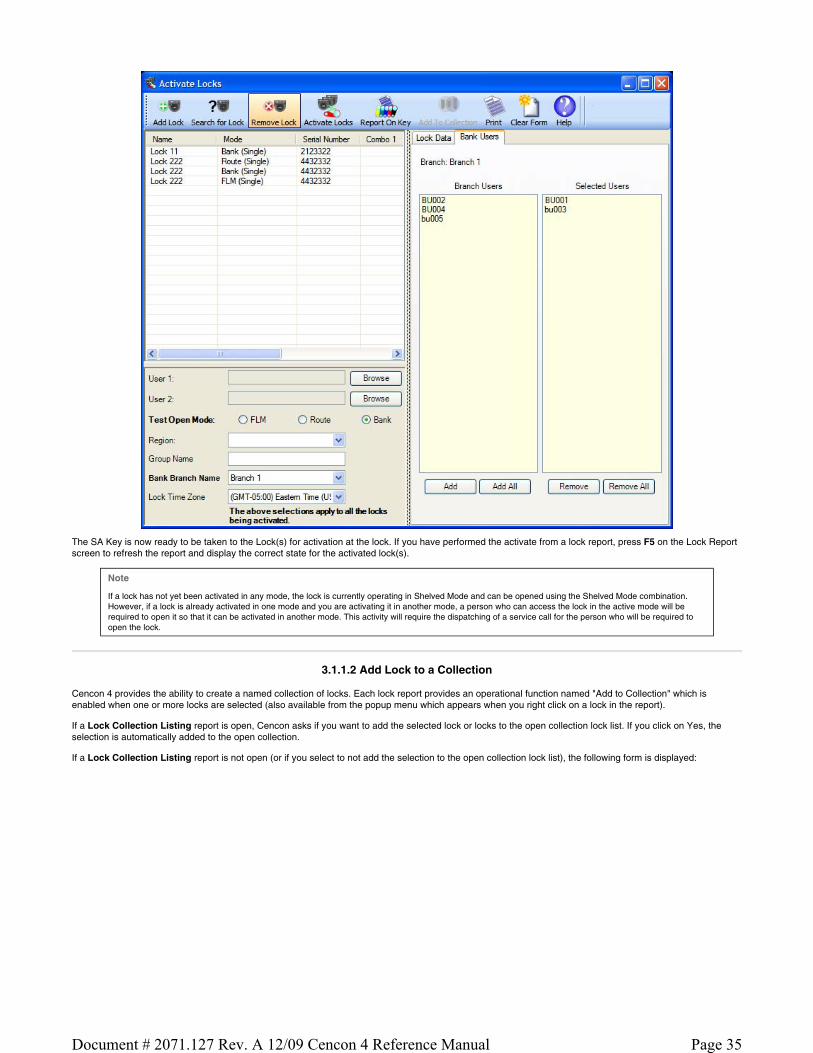
The SA Key is now ready to be taken to the Lock(s) for activation at the lock. If you have performed the activate from a lock report, press F5 on the Lock Report screen to refresh the report and display the correct state for the activated lock(s).
Note
If a lock has not yet been activated in any mode, the lock is currently operating in Shelved Mode and can be opened using the Shelved Mode combination. However, if a lock is already activated in one mode and you are activating it in another mode, a person who can access the lock in the active mode will be required to open it so that it can be activated in another mode. This activity will require the dispatching of a service call for the person who will be required to open the lock.
3.1.1.2 Add Lock to a Collection
Cencon 4 provides the ability to create a named collection of locks. Each lock report provides an operational function named "Add to Collection" which is enabled when one or more locks are selected (also available from the popup menu which appears when you right click on a lock in the report).
If a Lock Collection Listing report is open, Cencon asks if you want to add the selected lock or locks to the open collection lock list. If you click on Yes, the selection is automatically added to the open collection.
If a Lock Collection Listing report is not open (or if you select to not add the selection to the open collection lock list), the following form is displayed:
Page 35Document # 2071.127 Rev. A 12/09 Cencon 4 Reference Manual

To add the selected locks to a collection, click on a collection name to select it and press Add Locks. The dialog also allows for the creation of a new collection and the display of the locks in an existing collection.
See Section 3.1.4 for more information on Lock Collections.
3.1.1.3 Add Lock to a Route
Cencon 4 provides the ability to create routes, which are groups of multiple locks in route mode that can be dispatched simultaneously. The Add Lock to a Route menu item is used to add the selected lock (or locks) to the currently open route listing. The menu item is disabled if no route lock report is open.
See Section 3.1.3 for more information on Routes.
3.1.1.4 Add Users to a Bank Lock
After a Bank mode lock is initially activated and placed into service, there will be times when it is necessary to add more Bank mode users to the lock. Cencon provides an easy method for doing this. Before users can be added to a lock, they must first be added to the Cencon PC system (into the same bank branch as the lock) using the Add User Keys function on the main Cencon screen (or by selecting the Add a User function under Operations on the User Operation report). See Add Users Sect. 3.2.1.
Note
Cencon Gen1 locks support a maximum of 32 bank users which may be assigned user IDs in the range 00 - 79. Cencon Gen2 locks support a maximum of 100 bank users which may be assigned user IDs in the range 0 - 999,999.
From a lock report, select one or more active bank locks (as long as they are in the same Bank Branch). Then from the Administration drop-down menu, chooseAdd Users to a Bank Mode Lock menu item. The following dialog is displayed:
Page 36Document # 2071.127 Rev. A 12/09 Cencon 4 Reference Manual
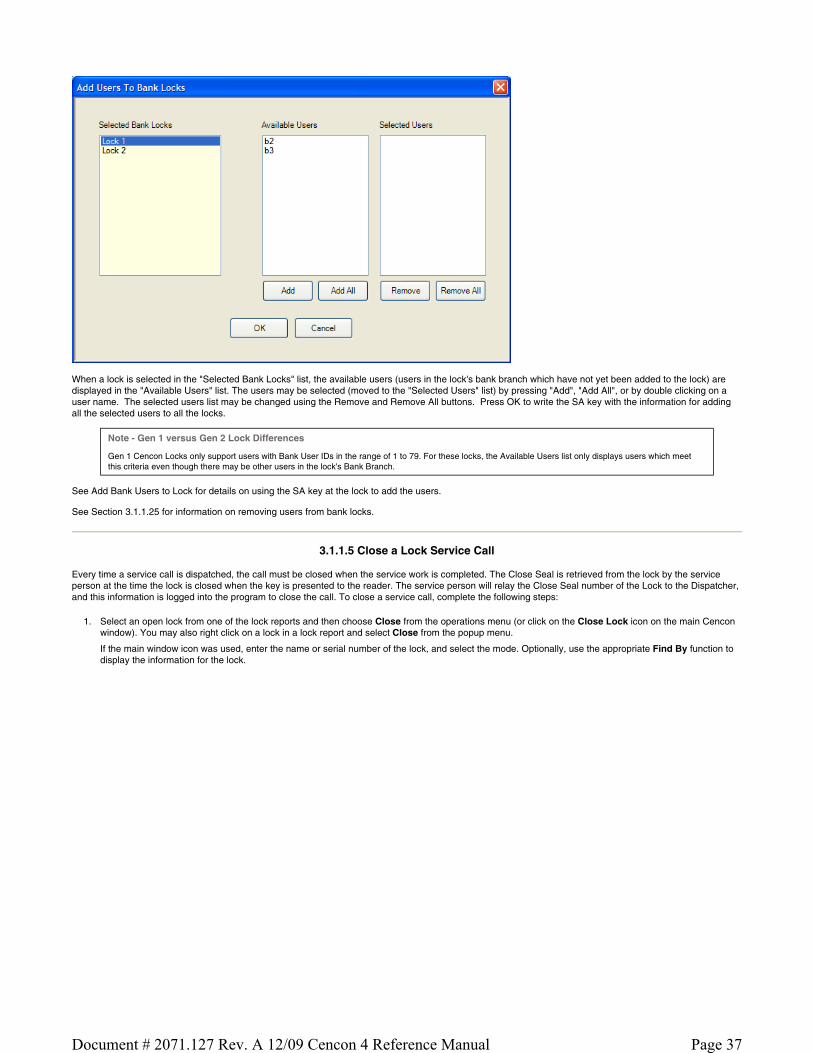
When a lock is selected in the "Selected Bank Locks" list, the available users (users in the lock's bank branch which have not yet been added to the lock) are displayed in the "Available Users" list. The users may be selected (moved to the "Selected Users" list) by pressing "Add", "Add All", or by double clicking on a user name. The selected users list may be changed using the Remove and Remove All buttons. Press OK to write the SA key with the information for adding all the selected users to all the locks.
Note - Gen 1 versus Gen 2 Lock Differences
Gen 1 Cencon Locks only support users with Bank User IDs in the range of 1 to 79. For these locks, the Available Users list only displays users which meet this criteria even though there may be other users in the lock's Bank Branch.
See Add Bank Users to Lock for details on using the SA key at the lock to add the users.
See Section 3.1.1.25 for information on removing users from bank locks.
3.1.1.5 Close a Lock Service Call
Every time a service call is dispatched, the call must be closed when the service work is completed. The Close Seal is retrieved from the lock by the service person at the time the lock is closed when the key is presented to the reader. The service person will relay the Close Seal number of the Lock to the Dispatcher, and this information is logged into the program to close the call. To close a service call, complete the following steps:
1. Select an open lock from one of the lock reports and then choose Close from the operations menu (or click on the Close Lock icon on the main Cencon window). You may also right click on a lock in a lock report and select Close from the popup menu.
If the main window icon was used, enter the name or serial number of the lock, and select the mode. Optionally, use the appropriate Find By function to display the information for the lock.
Page 37Document # 2071.127 Rev. A 12/09 Cencon 4 Reference Manual

2. Enter the two-digit or four-digit Close Seal of the Lock (relayed by the service person).
Note
An error message is displayed if you enter an incorrect close seal and the Lock will not be closed. The default dispatcher and supervisor authorizations allow three successive attempts to close a call. After a third unsuccessful entry the system requires a Special Supervisor to close the lock. The number of close attempts can be customized by modifying the authorization definitions for the dispatcher, supervisor, and other any roles besides the Special Supervisor.
3. Click on Close Lock. If the close seal was entered correctly, the program displays a message to indicate that the Lock has been closed.
Note
The Close Result for a normal close is "Lock call closed" (Gen1 and Gen2 locks).
For Gen2 locks only:
The Close Result for a lock with a triggered duress alarm is "Lock call closed. Close seal indicates duress."
The Close Result for a lock with a low/dead/removed battery or with a clock which has not been set is "Lock call closed. Close seal indicates low clock battery or clock not set."
3.1.1.6 Close a Lock Service Call Using a Key
Every time a service call is dispatched, the call must be closed when the service work is completed. The Close Seal is retrieved from the lock by the service person at the time the lock is closed. This function allows the dispatcher to close a call (or multiple calls) by reading the close seals from the Lock User key rather than selecting locks from a lock report and typing in the close seal(s). To close a service call using a key, complete the following steps:
1. Insert the user's key into the appropriate port of the key reader. 2. Click the Close Lock With Key icon on the main Cencon screen or open one of the lock reports and select Close Locks With User Key from the
Operations menu.
Cencon reads the lock information from the key and displays the locks which have been closed as shown below:
Page 38Document # 2071.127 Rev. A 12/09 Cencon 4 Reference Manual

Note
The close with key process uses the event time stamp from the lock (stored with the close seal on the key) to determine the valid seals. If the lock has a bad battery or the clock is not set, this time will be incorrect and you will receive a message indicating that there are no valid close seals on the key. If you see this message, you must enter the close seal manually in the right column of this form.
If you need to process a different user's key, insert the key into the reader and press Read Close Seals from Key.
If the key contains the close seal for the lock, the close seal is displayed as shown above (for lock 941090). If the seal is not on the key, select the lock, and enter the seal in the Close Seal field.
3. If you do not want to close one of the displayed locks, select the lock and press the Remove Lock from Being Closed button. The lock will remain in the list but its background will be grey.
4. Press the Close Locks toolbar button to close those locks which have close seals.
An error message is displayed if you enter an incorrect close seal, and the Lock will not be closed. The locks which were not closed because of an error condition are highlighted in red. Place the mouse cursor over the highlighted lock name to display the specific error message.
If the close seal was entered correctly, the program displays a message to indicate that the listed locks have been closed:
Page 39Document # 2071.127 Rev. A 12/09 Cencon 4 Reference Manual

3.1.1.7 Close Locks Based on Verify of Open With Key
Every time a lock is dispatched, the call must be closed when the service work is completed. Normally, a Close Seal is retrieved from the lock by the service person at the time the lock is closed. This function allows the dispatcher to close a call without a close seal by using the audit information on the key to verify that the lock was opened.
Note
This menu item is one of the carry-over functions from the Activation Only software, a program designed to meet the needs of companies who install, activate, and test the lock on ATMs in a factory environment. The primary purpose of this function is to allow the lock bolt to stay retracted while the empty ATM is in
transit to the field, and yet be able to have this call closed in the software (once the required open-only record is found on the key). This allows the safe door of the ATM to be shut but not locked during shipping. After the ATM arrives at its intended destination and is bolted to the floor, the first Lock User who extends the lock bolt and powers the lock will be asked to present the FLM or Route key. A close seal will display on the lock; however, this close seal does not need
to be entered into the software because this menu item was already used to close this lock.
In the normal day-to-day operation of most companies using this function would not be recommended and should be restricted to only the Special Supervisor role.
To close a service call without a close seal, complete the following steps:
1. Insert the user's key into the key reader. 2. Open one of the lock reports, select the Operations menu, and then the Close Locks Based on Verify of Open With Lock User Key menu item.
3. Cencon reads the lock audit information from the key and displays the locks which have been opened as shown below:
Page 40Document # 2071.127 Rev. A 12/09 Cencon 4 Reference Manual

If you need to process a different user's key, insert the key into the reader and press Read Audits from Key.
Note
This function cannot be used if the key contains valid close seals. If you see the following message, press OK and select the Close Lock with Key function to perform the close.
4. To view the information for a lock, select it in the list on the left side of the window. 5. Press the Close Locks toolbar button.
Warning
The analysis of the audit data on the key involves comparison of the dispatch time on the Cencon system and the open time from the key. To insure accurate comparisons, the time on the key must be reasonably close to the system time. Cencon displays an error message if the two
times differ by more than 5 minutes.
3.1.1.8 Delete Shelved Lock
This menu allows you to remove a Lock from the list of locks shown on the Lock Report. This option should only be used when a Lock has been shelved and responsibility for the lock has been transferred to another company. The lock must be closed first in order to be deleted using this function. Also, before deleting the lock, it should be shelved unless it has been destroyed and cannot be shelved. In that case, a Special Supervisor would need to use the Force Delete of Unshelved Lock function.
Hint
If a Lock is simply being temporarily removed from service, you should only shelve the lock, not delete it, so that any information that has been input into the database about this lock can remain with the lock file. That way, if the lock is reactivated, the data will not need to be reentered.
To delete a Lock, complete the following steps:
1. Open a lock report. 2. Select the shelved lock which is to be deleted.
3. Select the Administration Menu. 4. Press Delete Shelved Lock. The Delete dialog is displayed:
Page 41Document # 2071.127 Rev. A 12/09 Cencon 4 Reference Manual

5. Click on Individual Lock Report if you want to view the lock details before completing the operation. 6. Click on Delete Shelved Lock to finish the deletion. 7. A Delete successful message should be displayed.
Warning
If an active lock is accidentally deleted, the lock record goes to the Lock History file and can be restored back to the Lock Report. (See Section 3.4.5 Lock History Report). However, if the information in the Lock History file is no longer available for whatever reason, any active lock that was deleted may have to
be drilled.
3.1.1.9 Dispatch a Lock
To dispatch a service call to open a lock, the Dispatcher issues the combination for a particular lock to a particular Lock User Key through the Cencon program and then relays that information to that Lock User. The Lock User then uses his or her key and the One Time Combination to open the lock.
1. To access the dispatch dialog, select a closed lock from a lock report and then right-click and select the dispatch menu item or press the Dispatch Lock icon on the main Cencon window. The Dispatch Lock form is displayed:
2. If the main window icon was used, enter the name or serial number of the lock and then use the appropriate Find function to display the information for
the lock. This information is automatically filled in if the lock was selected from a lock report.
3. You can optionally click the Individual Lock Report button to display details on the status of the specified lock. 4. Enter the User ID of the person who will be assigned to the call. You may also click on the Browse button to select a user from the User ID report.
Page 42Document # 2071.127 Rev. A 12/09 Cencon 4 Reference Manual

Note
If you are using Lock Groups, make sure that the user that you assign to the call is authorized to service the lock.
5. If the Lock is in dual mode (requiring two users), enter the second User ID. Note that if one of the users has time windows set up, the other user must have time windows and the two sets of time windows must overlap.
6. Second Line Maintenance Call - Cencon provides a lock open alarm function which allows you to display a list of those locks have been open within a set time window (see Lock Open Alarm). If this dispatch is in FLM mode and is going to cause the lock to possibly be open for an extended period, check the Dispatch as Second Line Maintenance Call option to indicate that the lock open alarm process should ignore this open lock (when the Ignore Locks Open for Second Line Maintenance check box is selected on the alarm setup form). Typically, first line service calls are for basic maintenance or problems that are easily resolved. The option to designate a dispatch as a Second Line Maintenance Call is not available in Route mode.
7. Click on Dispatch to proceed with the dispatch. The system will display the next One Time Combination(s) that will open the lock.
Relay this information to the service personnel for opening of the lock.
Note
The combination issued is only valid for the user to whom it is issued. It is not possible to issue the next one-time-only combination for this same Lock until you have closed this service call.
When the lock is successfully dispatched, the Close Lock button is enabled. Click on the Close Lock button to open the Close Lock form for this lock. Press Exit to close the Dispatch Lock form.
3.1.1.10 Edit Lock Data
This option allows you to change the data for a single lock or a group of locks.
Note
Editing data on a lock will not change the lock information in historical reports, such as the Lock Log (currently dispatched locks) or past records in the Activity Log.
Note
You may select a maximum of 200 locks to be edited.
1. Select one or more locks in one of the Lock Reports and then choose "Edit Lock Data" from the drop down or popup menu.
Page 43Document # 2071.127 Rev. A 12/09 Cencon 4 Reference Manual

The selected locks are shown in the list on the left of the dialog. Clicking on a lock name updates the information in the window with the data for that lock.
2. Modify the desired data fields by checking the corresponding check box and entering new data. Note that the data will be changed for all the selectedlocks. Select "Update all modes of all locks" if you also want all modes of each lock to be updated.
Mapping Considerations...
Cencon supports mapping of lock locations using Microsoft MapPoint and the MapQuest internet service. These applications require accurate location information. In addition, MapQuest requires that the state/province name be the standard two character abbreviation.
3. Click on Update. A confirmation summary message is displayed:
3.1.1.11 Export Lock Data
This function allows you to export an XML file containing lock data. This is useful for transferring access of locks from one branch or one database of a company to another database within that company. For example, some companies have one Cencon system they use only for lock activation and testing. Once the lock is active in System A, and saved as an XML file as described below, the file is delivered electronically and imported into the System B, the company's main dispatch center's database. At this point, System B can begin dispatching combinations to this lock, and System A should delete that lock file. (See Section 3.1.1.13 Import From File.)
To export a lock file, complete the following steps:
1. Open a lock report. 2. Select the locks you want to export. 3. Select the Administration Menu.
4. Click Export the Selected Locks To an XML File.
The Select File dialog is displayed.
5. Select a location and file name for the XML file and click Save.
A "Success" message should be displayed.
Warning
A Cencon lock XML file that is created is only intended for importing into another database within the same company (using the same security information.) The file should not be opened or used for any other purpose than importing into that company's Cencon software. Failure to heed this warning may result
in data loss and drilling of containers.
Page 44Document # 2071.127 Rev. A 12/09 Cencon 4 Reference Manual

3.1.1.12 Force Delete of an Unshelved Lock
This function allows you to forcibly remove a Lock from the list of locks in the Lock Report, regardless of it's status. In most normal situations, a lock would be taken out of a system after it has been properly shelved and the verify shelve key operation has updated the status of the lock on the system. At that point, it could be deleted using the Section 3.1.1.8 Delete Shelved Lock.
This function is helpful for database cleanup of lock files by a manager in cases where there is no physical, active lock with this lock serial number in a customer's system. For example, a lock serial number may have been typed in incorrectly during the activation process, thereby creating an SA activation key and a lock file on the system both of which are useless. Another example is a lock that was destroyed and is no longer able to be used or shelved. It is recommended to control the access to this function to the highest level of managers.
Danger
This feature should be used with great care since you will be bypassing all the functions of Cencon which synchronize lock operations.
To force the deletion of a Lock, complete the following steps:
1. Open a lock report. 2. Select the locks which are to be deleted.
3. Select the Administration Menu. 4. Click Force Delete of Unshelved Locks. The following verify dialog is displayed:
5. Click on OK to finish the deletion. 6. A Delete successful message should be displayed.
3.1.1.13 Import Lock Data
This function allows you to import an XML file containing lock data from another Cencon database within your company. This is useful for transferring locks and remote activation of locks.
To import a lock file, complete the following steps:
1. Open a lock report. 2. Select the Administration Menu.
3. Press Import Locks from XML File. 4. The Import dialog is displayed. Press Import Locks From File and select the XML file containing the locks you want to import to your system. Below is a
sample of this dialog after a file containing one lock has been imported:
Page 45Document # 2071.127 Rev. A 12/09 Cencon 4 Reference Manual

5. Click on a lock row to display the lock details on the right section of the window. 6. Select a lock and click on Remove Lock from List to prevent an import of that lock.
7. click on Add Locks to Cencon Database to perform the import. 8. "Imported successfully" or an error message is displayed in the Result column for each lock.
Warning
A Cencon lock XML file that is created is only intended for importing into another database within the same company (using the same security information.) The file should not be opened or used for any other purpose than importing into that company's Cencon software. Failure to heed this warning may result
in data loss and drilling of containers.
3.1.1.14 Individual Lock Report
The Individual Lock Report is used to display the details of a single lock, including if the lock is open and the previous combination dispatched to the lock.
From any of the lock reports, select the lock you want to display additional information on. Right click on the lock, and select Individual Lock Report.
A window is displayed that looks similar to the following. The information displayed will vary depending on what information has been entered for the lock and if the lock is open or not.
The File menu provides access to Save and Print functions.
3.1.1.15 Manager Force Close w/o Seal
This function allows you to forcibly close a Lock without knowing the close seal. Personnel who have been trained in the Cencon software will understand the rare situations where the use of this function may be beneficial. The main example is if a database had crashed and several combinations had been used at a lock since the previous back-up. When the back-up database is restored, to get the software audit count back in synchronization with the lock, once the manager knows the audit count of the lock, a series of dispatches and force closes could be done in the software. For Gen2 locks, an alternate method of recovery is explained in Section 3.1.1.22 Resynchronize the Cencon Database with Lock.
Danger
This feature should be used with great care since you will be bypassing the functions of Cencon which synchronize lock operations. The ability to access this function should be limited to only managers with the highest authority who have been fully trained to know when using this function is appropriate.
If managers habitually allow locks to be forced closed and the dispatched combination not used, the risk is very great that containers will need to be drilled
because the Cencon system is not being used as instructed. Out-of-synch situations often result in drilling when combined with lost combinations, lost keys, and abuse of the force close function.
Page 46Document # 2071.127 Rev. A 12/09 Cencon 4 Reference Manual

To close a lock without a close seal, complete the following steps:
1. Open a lock report. 2. Select the lock which is to be closed.
3. Select the Administration Menu. 4. Press Manager Force Close w/o Seal. The following close dialog is displayed:
Clicking the mouse on the "click here for more details" text provides the following additional information:
5. Click on Individual Lock Report if you want to view the lock details before completing the operation. 6. Click on Close Lock to finish the Force Close operation. A Close successful message should be displayed once you verify that this is what you truly want
to do.
3.1.1.16 Map Lock Locations
Cencon 4 provides the ability to send lock address information to external mapping software. Cencon 4 supports the following:
Microsoft MapPoint. MapPoint is a commercially available product and is not included in the Cencon 4 software package. MapQuest - a free internet mapping service (an active internet connection is required).
Note
Page 47Document # 2071.127 Rev. A 12/09 Cencon 4 Reference Manual

MapPoint is not supported under the 64 Bit version of Cencon.
Both of the above products require that accurate address information be entered in the proper data fields for each selected lock. Use the Preferences dialog (on the main Cencon window) to select the desired mapping software.
To display lock locations on a map, select one or more locks from one of the lock reports, and then choose Display the Lock Location on a Map.
Note
Microsoft MapPoint can display multiple lock locations simultaneously. If using MapQuest, only select one lock at a time for displaying on the map.
If the address information appears to be sufficient to locate the lock, Cencon passes the data to the mapping program for display. Refer to the mapping software's documentation for information on using the specific mapping product.
Mapping Considerations
The mapping applications require accurate location information. In addition, MapQuest requires that the state/province name be the standard two character abbreviation.
Sample MapPoint map displaying two lock locations:
3.1.1.17 Reassign a Service Call
The Dispatcher may find it necessary to reassign a call to a different user than the one originally scheduled to perform the work.
The Dispatcher can also temporarily "unassign" an FLM user from an FLM service call; however, the unassign function must be accessed via the lock report. (See 3.1.1.24 Unassign an FLM Call). Typing in an asterisk on the Reassign user field no longer unassigns the call as in previous versions. The unassignoption is designed for use when a user has accidentally been dispatched to the wrong lock and must be freed up to service the correct lock.
To reassign a service call, complete the following steps:
Select an open lock from one of the lock reports and then choose the Reassign menu item or click on the Reassign icon on the main window.
If the main window icon was used, enter the name or serial number of the lock and then use the appropriate Find function to display the information for thelock.
Page 48Document # 2071.127 Rev. A 12/09 Cencon 4 Reference Manual

The Name of the user to whom the service call is currently assigned is displayed, along with the lock combination. If the Lock was assigned in Dual mode, both names and both combinations are displayed.
Enter the new User Names(s) in the appropriate Name fields to reassign the call (or use the Browse function to select a user name). Click on Reassign.
If the reassign is successful, the system displays the combination(s) for the new user(s).
Note
Note that both combinations (the user originally dispatched and the user who was reassigned) have the ability to open the lock. However, only the combination that is entered first will actually open the lock. Once a combination is entered, the other combination will be invalid and will not open the lock. Only one Close
Seal is able to be retrieved from the lock for a given call, no matter how many different users to which the call was reassigned.
3.1.1.18 Reissue an Activate Key
This function provides for the reissue of an activation key in the event of SA key loss or data error.
From a lock report, select any one of the locks which should be on the activation key (the software does not allow you to select multiple lock for this function - just select any one of the locks and the software will automatically search for any others that were activated on that same SA key based on the original time the SA key was programmed and the lock status). Click on the Administration Menu, followed by Reissue Activate Key for Locks. The following dialog is displayed. Note that all the locks which were on the original key are displayed.
Page 49Document # 2071.127 Rev. A 12/09 Cencon 4 Reference Manual

If the list is correct, insert an SA key into the reader and press OK. The message "SA Key Reissued" is displayed when the key is ready.
Any locks that have been successfully activated, which is evident in the software because the audit count is 2 or higher, will not allow a Reissue of an Activation Key. Furthermore, any locks that were imported from a previous version of Cencon or CenBank software will not allow a Reissue of an Activation Key, even if the audit count is still at 1.
Note
The original combination(s) dispatched in to the FLM or Route Lock User Key during the activation process will still work after the Reissued Activation SA key is used. If the activation combination(s) were not written down, they can be obtained via the Individual Lock Report or Lock Operations Report.
3.1.1.19 Remove Users from a Bank Lock
There will be times when it is necessary to delete a Bank Mode Lock User’s authorization to access a bank lock. This procedure will delete the user’s authorization to access a bank lock but will not remove the user from the Cencon System.
From a lock report, select one or more bank locks within the same Bank Branch ID, and then select the "Administration/Remove Users from a Bank Lock" menu item. The following dialog is displayed:
When a lock is selected in the "Selected Bank Locks" list, the users currently assigned to the lock are displayed in the "Lock Users" list. The users may be selected (moved to the "Users to be Removed" list) by pressing "Remove" or by double clicking on a user name. The "Users to be Removed" list may be changed using the Restore and Restore All buttons. Press OK to write the SA key with the information for removing all the selected users from all the locks.
Page 50Document # 2071.127 Rev. A 12/09 Cencon 4 Reference Manual

Note
This function displays an error if you try to delete all the users (or all but 1 user for a lock in dual mode). You must have at least the minimum number of users required to open the lock.
See Delete Bank Users from Lock for details on using the SA key at the lock to remove the users.
Caution
If an SA key is programmed in the software to Delete Bank Users the manager should ensure that the key is properly used successfully at all of the intended locks. If any errors display during the process of reading the Delete Users SA key a second SA key initialized for Bank Mode User
Table Download (see section 3.5.6 Initialize a Key to Retrieve the Bank Users from a Lock) should be used at the lock and read in the software. If the Delete Bank Users key was not used successfully at the intended locks, it is possible that the particular Bank User Key(s) can
still open the lock, even though the software shows that an SA key was created to delete the key(s) from the lock.
See Section 3.1.1.24 for information on adding additional Bank Mode Lock Users to bank mode locks.
3.1.1.20 Rename Lock
This menu option allows you to rename a lock.
To rename a lock:
1. Open a lock report. 2. Select the lock to be renamed.
3. Select the Administration Menu. 4. Press Rename Lock. The Rename Lock dialog is displayed:
5. Enter a new name for the lock. 6. Click on Rename.
3.1.1.21 Replace Lock
This menu option allows you to replace a lock when it must be removed due to the lock back cover having been destroyed, due to factory reset of the back cover, or for any other reason. This process creates, in essence, a new activation SA key to be used to activate a lock that is not currently active in a particular mode. By using the Replace Lock function, the lock data stored in the Cencon software (name, description, etc.) will not have to be retyped and the Delete a Lock function will occur automatically for the lock serial number being replaced.
Warning
A Cencon Lock that is to be replaced must NOT be deleted from the Cencon system. The Lock must be seen as active in the PC system and closed (i.e., no combination dispatched) to be properly replaced.
To replace a lock:
1. Open a lock report. 2. Select the lock to be replaced.
3. Select the Administration Menu. 4. Press Replace Lock. The Replace Lock dialog is displayed:
Page 51Document # 2071.127 Rev. A 12/09 Cencon 4 Reference Manual

5. Enter the Serial Number of the new lock.
Note
The lock serial number will automatically be changed for all active modes of the lock.
6. If the Lock Mode is not Bank, enter the RSP/FLM User ID that you want to do the replacement of the lock. 7. Insert an SA key into the key reader.
8. Click on Replace Lock. 9. The combination for opening the lock is displayed as shown below (the combination will be blank for Bank Mode):
10. Record the combination and select Exit to close the window.
Note
You can undo the replacement of a lock, where the lock being replaced was in error.
The data for the lock being replaced is kept in the lock history table with the original serial number, and placed in a lock status of 'Replaced'.
To undo the lock replacement, delete the new lock and use the Undo Replace function in the Lock History Report.
Page 52Document # 2071.127 Rev. A 12/09 Cencon 4 Reference Manual

3.1.1.22 Resynchronize the Cencon Database with a Lock
Note
This feature is only available for Cencon Gen2 locks.
This function allows you to resynchronize the misaligned audit count in the software for a Gen2 lock with the actual audit count of the lock. The resynchronization occurs by retrieving data from the lock with the grey ReSync key and then reading this key in the software which updates the corresponding information in the Cencon database. This procedure consists of the following:
1. Insert a dark grey resynchronization key into the Key Reader. 2. From a lock report, select a Gen2 lock and Initialize a Key to Resynchronize Lock (Gen2) from the Administration menu.
3. A message is displayed when the initialization is complete. At this point, the lock's report entry is marked with a red background to indicate that it is in the process of being resynchronized. Use the Cancel a Resynchronize Lock Operation (Gen2) menu item to cancel this process. 4. Take the key to the selected lock and retrieve the lock data. (See Resynchronize the Database with a Lock for details.)
5. Insert the returned key into the key reader and select Resynchronize the Database with Lock Data (Gen2) from the Administration menu. (It does not matter if any lock or locks are selected when reading the ReSync key since the software knows which lock to update based on the information on the
key.) A status message is displayed when the database update is complete and the red background color in the lock report is removed.
Note
Once a ReSync key has been issued for a particular lock and mode that is not already dispatched, that lock in the lock report signifies this condition by being highlighted in light red. The lock will not allow a new dispatch to occur for a particular mode while that lock and mode are in the resynchronize state (when a
ReSync key has been programmed for that lock, but has not yet been returned and read in the software.)
If the ReSync key was issued on a lock that was already dispatched, the lock remains highlighted green. In this condition, be aware that the a combination dispatched may or may not open the lock, and if the combination was used, the data on the returned ReSync key may be invalidated depending on the order of
events.
3.1.1.23 Shelve Lock
This option allows you to deactivate (shelve) a lock mode or modes for a lock that is currently active. At the time the SA key is prepared, a combination is dispatched (if FLM or Route mode is being shelved) to be used to open the lock to perform the shelving. The shelving combination, the prepared SA Key, a valid Lock User Key (FLM, Route, or Bank mode), and a Change Key are then used to perform the shelving procedure on the Lock. To program the shelve key:
1. Open a lock report. 2. Select the locks to be shelved.
3. Select the Administration Menu. 4. Select Shelve Locks. The Shelve dialog is displayed:
5. Insert an SA key into the Key Reader. 6. Click on a lock to view its details before processing.
7. Click on Write Shelve Lock Key.
Page 53Document # 2071.127 Rev. A 12/09 Cencon 4 Reference Manual

8. A Shelve success summary message is displayed and the shelving combinations are displayed in the shelve form.
9. The SA Key is now ready to be taken to the Lock(s) for shelving at the lock (see section 4.2.10 Shelve Lock (at Lock) for details). Once shelving has been completed, the SA Key must be returned to the PC System to verify the process for each lock shelved.
Note
If a lock was opened and closed but not shelved while it was opened, another combination must be issued to the FLM or Route Person as a Service Call. This dispatch will change the lock status from Pending Shelve back to Active; however, the shelving key that was previously created is still valid to
be used. The lock can then be opened again and the shelving can be completed.
Note
If a lock is being shelved in all modes, the Shelved Mode combination returns to the Default Factory Combination of 50-25-50.
3.1.1.24 Unassign an FLM Service Call
An FLM Lock User can be "unassigned" from an FLM service call. This option is designed for use when a user has accidentally been dispatched to the wrong lock and must be freed up to service the correct lock. To unassign a service call, complete the following steps:
Select an open lock from one of the lock reports and then choose the Unassign menu item. This operation pertains only to FLM mode locks; the menu item is disabled for Route mode locks.
The Name of the user to whom the service call is currently assigned is displayed, along with the lock combination. If the Lock was assigned in Dual mode, both names and both combinations are displayed.
Click on Unassign Lock.
If the unassign is successful, the system displays a message in the Result area of the Unassign window.
Caution
Unassigning a FLM user from a call does not cancel the call. The lock is still in an open status in the software. In fact, be aware that if the FLM user was told the combination before the unassign occurred, the FLM technician could still use the combination to open the
lock. Once a combination is dispatched to a user, the only way to prevent that user's combination from working at the lock is to reassign the combination to a 2nd user, and have the 2nd user open the lock with that combination before the 1st user.
Note
When an FLM lock is in an unassigned state, the next time a user needs to service that lock, the Reassign function must be used. Even if the original user that had been unassigned opens the lock, the lock still must be reassigned (or assigned back to the original user) in order to close the call. See
section 3.1.1.17 Reassign a Service Call for details on the Reassign function.
Page 54Document # 2071.127 Rev. A 12/09 Cencon 4 Reference Manual

3.1.1.25 Undo Replace/Deleted Lock History Report
This report lists a history of deleted lock records. Each time a lock is deleted or replaced, the record from the Lock report is moved to the Deleted Lock History report. Thus, the two reports have the same initial search screen and report format. See the Lock Report for more information.
The following operations result in an entry in the Deleted Lock History report:
Delete shelved lock Force delete of unshelved lock
Replace lock Update activation of Gen2 locks activated in compatibility mode
The only Operations for this report are:
Restore the Lock (Selected Mode Only), This function attempts to restore only the lock data on the selected line (does not look for other modes of the same lock).
Undo the Replacement of the Lock (All Modes). Use this function on locks with a Status of "Replaced" to undo (restore) the replacement of all modes of the selected lock. As a safety precaution, the lock must have already been deleted from the lock table.
If the lock was open when it was deleted (occurs if the Force Delete function was used), the following dialog is displayed:
A successful restore displays the following:
3.1.1.26 Update Activation of Gen2 Locks Activated in Compatibility Mode
This option allows you to change the status of a Gen2 lock which was activated in Gen1 compatibility mode. Gen2 locks which are activated under a previous version of Cencon or which were activated with Cencon 4 using a PCI card are automatically placed in what is called "compatibility mode". In this mode, Gen2 locks behave mostly like Gen1 locks and do not support many Gen2 unique functions. When a Cencon Key Box is available for use with the Cencon 4 system, these locks should be updated to give them full Gen2 functionality. To update Gen2 locks in compatibility mode:
1. Open a lock report. 2. Select the Gen2 lock(s) to be updated. (The Gen2 Compatibility Mode locks will have the Lock Name highlighted in grey rather than white or blue.)
3. Select the Administration Menu. 4. Press Update Activation of Gen2 Locks Activated in Compatibility Mode. The following form is displayed:
Page 55Document # 2071.127 Rev. A 12/09 Cencon 4 Reference Manual
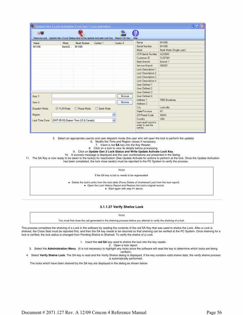
5. Select an appropriate user(s) and user dispatch mode (the user who will open the lock to perform the update) 6. Modify the Time and Region values if necessary.
7. Insert a red SA key into the Key Reader. 8. Click on a lock to view its details before processing.
9. Click on Update Gen 2 Lock Status and Write Update Activate Lock Key. 10. A success message is displayed and the user combinations are presented in the dialog.
11. The SA Key is now ready to be taken to the lock(s) for reactivation (See Update Activate for actions to perform at the lock. Once the Update Activation has been completed, the lock close seal(s) must be reported to the PC System to verify the process.
Note
If the SA key is lost or needs to be regenerated:
Delete the lock's entry from the lock table (Force Delete of Unshelved Lock from the lock report). Open the Lock History Report and Restore the lock's original record.
Start again with step #1 above.
3.1.1.27 Verify Shelve Lock
Note
You must first close the call generated in the shelving process before you attempt to verify the shelving of a lock.
This process completes the shelving of a Lock in the software by reading the contents of the red SA Key that was used to shelve the Lock. After a Lock is shelved, the Close Seal must be reported first, and then the SA key needs to be returned so that shelving can be verified at the PC System. Once shelving for a lock is verified, the lock status is changed from Pending Shelve to Shelved. To verify the shelve of a Lock:
1. Insert the red SA key used to shelve the lock into the key reader. 2. Open a lock report.
3. Select the Administration Menu. (It is not necessary to highlight any locks since the software will read the key to determine which locks are being verified.)
4. Select Verify Shelve Lock. The SA key is read and the Verify Shelve dialog is displayed. If the key contains valid shelve data, the verify shelve process is automatically performed.
The locks which have been shelved by the SA key are displayed in the dialog as shown below:
Page 56Document # 2071.127 Rev. A 12/09 Cencon 4 Reference Manual

5. If you need to process a different SA key, insert the key into the Key Reader and click on Read Shelve Lock Key.
If the process is successful, the message "Locks shelved successfully" is displayed, and the database records for the Locks shelved through the use of the Supervisor Audit Key are placed in the "Shelved" mode. These Locks cannot be used again until the "Activate Lock" process is used to re-activate them.
Note
If a lock was opened and closed but not shelved while it was opened, another combination must be issued to the FLM or Route Person as a Service Call. This dispatch will change the lock status from Pending Shelve back to Active; however, the shelving key that was previously created is still valid to be used. The
lock can then be opened again and the shelving can be completed.
3.1.2 Open Lock Log
This report lists information pertaining to open locks. The following Search screen is displayed prior to generating the report to allow filtering for specific lock records:
Sample Open Lock Log:
Page 57Document # 2071.127 Rev. A 12/09 Cencon 4 Reference Manual
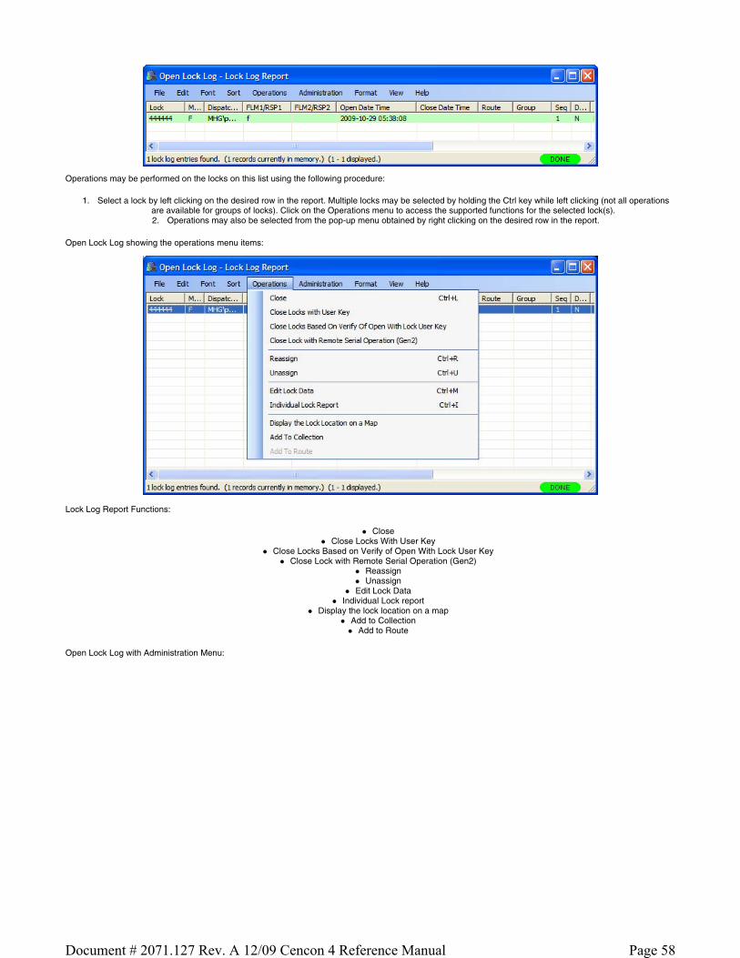
Operations may be performed on the locks on this list using the following procedure:
1. Select a lock by left clicking on the desired row in the report. Multiple locks may be selected by holding the Ctrl key while left clicking (not all operations are available for groups of locks). Click on the Operations menu to access the supported functions for the selected lock(s). 2. Operations may also be selected from the pop-up menu obtained by right clicking on the desired row in the report.
Open Lock Log showing the operations menu items:
Lock Log Report Functions:
Close Close Locks With User Key
Close Locks Based on Verify of Open With Lock User Key Close Lock with Remote Serial Operation (Gen2)
Reassign Unassign
Edit Lock Data Individual Lock report
Display the lock location on a map Add to Collection
Add to Route
Open Lock Log with Administration Menu:
Page 58Document # 2071.127 Rev. A 12/09 Cencon 4 Reference Manual

Administration Functions:
Rename Replace
Undo Replace Manager Force Close w/o Seal Force Delete of Unshelved Lock
Remote Serial Operations with Lock (Gen2)
Note
If any information (description, group ID, address, etc.) is edited about a lock that is already in an open status, the updated information does not appear in the Lock Log. The information about each lock is whatever was in the lock file before the lock was dispatched.
3.1.3 Route Report
The Route Report is used to display and manage routes of locks. From the main window, click on Route Report. A window similar to the following is displayed:
A variety of common operations can be done with the report, to include printing, saving in various formats, and sorting the contents of the report. You can refer to these common report operations in section 3.0 Reports.
The operations menu provides access to a set of operations unique to the Route Report as shown below:
Page 59Document # 2071.127 Rev. A 12/09 Cencon 4 Reference Manual

Add Route
This operation allows you to add a new route. You can do this by selecting Add a Route from the Operations menu.
The following dialog is displayed:
You will need to enter a name for the route you want to create. Optionally you can set a customer ID and region ID. If you are using region control, and currently logged in as a Global user, you will need to set the region ID to match the region assigned to the locks you are going to place on the route. If the current dispatcher is restricted to a local region, then that region will automatically be assigned to a new route being created. Once you have set up the information for the new route, click the OK button.
Edit Route Data
This operation allows you to edit the information for an existing route. You will need to first select the route you want to edit from the report. Then select Edit Route Data from the Operations menu. A dialog similar to the following is displayed.
Edit the information for the route as desired, and then click on OK. A confirmation message will be displayed for the update of the route.
Delete Route
This operation allows you to delete an existing route. You will need to first select the route you want to delete from the report. Then select Delete Route from the Operations menu. A dialog similar to the following will be displayed.
Page 60Document # 2071.127 Rev. A 12/09 Cencon 4 Reference Manual

Select Yes to proceed with deleting the route. If the route has locks open, they can still be closed out from the Lock Report or the Open Lock Log Report. If the route is later recreated with the same name, any open locks on the route will automatically be added back to the report.
Rename Route
This operation allows you to rename an existing route. You will need to first select the route you want to rename from the report. Then select Rename Route from the Operations menu. A dialog similar to the following is displayed.
Enter a new name and press OK to proceed with renaming the route.
Route Lock Listing
This operation allows you to display a report of the locks on a route, as well as manage the locks on a route. You will first need to select the route you want to display from the report. Then select Route Lock Listing from the Operations menu. The Route Listing Report will be displayed for the route you selected. See section 3.1.3.1 Route Listing Report for details on using the Route Listing Report. An alternative method is to double-click on the route you want to display. This operates in the same manner as selecting the option from the Operations menu.
Import All Routes From Route Directory...
This operation allows you to import all the route files (.RTE) found in the current route directory. The route directory is specified in the Cencon preferences settings.
Caution
The default key assignments do not import from the .RTE file.
Select Import All Routes From Route Directory from the Operations menu. If region control is active, the following dialog is displayed to select the region to assign to the routes being imported:
Select the region you want to assign to the routes files being imported, and select OK. The route files in the directory are imported, and the status indicator at the bottom of the Route Report changes to Import. As routes are imported, the status bar displays their names, and the number of routes to be imported. If the Route Report is closed, then the import of the route files will be stopped. Once all of the route files have been imported, a message similar to the following will be displayed to indicate completion of the import. If one of the routes being imported already exists by the same name assigned to a different region, then that route file import will fail. A route import can also fail if none of the locks assigned to the route actually exist in the Cencon System database. This will not prevent the import of the other route files.
Page 61Document # 2071.127 Rev. A 12/09 Cencon 4 Reference Manual

Select a Route File to be Imported to the Database
This operation allows you to import a specific route file. Select Select a Route File to be Imported to the Database from the Operations menu. A dialog similar to the following is displayed to allow you to select the file to import:
If region control is active, the following dialog will be displayed to select the region to assign to the route being imported. You will need to select the region you want to assign to the route being imported, and select OK.
The route file will then be imported, and the Route Report will be updated with the name of the new route. If the route already exists, the existing route will be over-written. If a route already exists by the same name assigned to a different region, then the import will fail.
When a route file is imported, the default user IDs for the route are not set. You will need to assign user(s) to the route before or during the dispatching of the route.
Archive Routes
Selecting Archive opens the following window:
Page 62Document # 2071.127 Rev. A 12/09 Cencon 4 Reference Manual

Enter the number of days for the archive (based on the last date the locks on the route were dispatched) and press OK to proceed to the confirmation screen:
The records are copied to the Route Archive table and removed from the Route table.
3.1.3.1 Route Listing Report
The Route Listing Report is used to display the details of a route of locks, and to allow administration of a route. It provides support for the following operations:
Adding locks to a route Deleting locks from a route
Setting the RSP user(s) for dispatch on a route Dispatching a route and listing the dispatched combinations
Reassigning all or part of a route and listing the updated combinations Closing all or part of a route by manual entry of lock close seals
Closing all or part of a route by reading from an RSP key Display additional details on selected individual locks.
Copy/Paste locks between routes
You can open this report on a route in the following manner:
Open the Route report from the main Cencon window by clicking on Route Report.
Open the route you want to display, by selecting the route name and double-clicking on it.
Alternatively, you can select the route name and right click on it. A drop down menu will be displayed. From the drop down menu, select Route Lock Listing. A window similar to the following will be displayed:
Page 63Document # 2071.127 Rev. A 12/09 Cencon 4 Reference Manual

A variety of common operations can be done with the report, to include printing, saving in various formats, and sorting the contents of the report. You can refer to these common report operations in section 3.0 Reports.
Note
This report is unique among Cencon reports in that it contains editable fields (yellow background) which are accessed with a left mouse click. Because the editable fields have priority, you must use the right mouse click to select rows for the menu operations.
The following window shows the set of operations unique to the Route Listing Report:
Browse To Add Lock To Route
This operation allows you to add locks to the route. 1 route listing report must be currently open to add locks to it. From the Operations menu, select Browse To Add Lock To Route. Alternatively, click on the Add Locks button on the tool bar. The Lock Report will be displayed, with the search automatically set up for route mode locks. If region control is active, the region will automatically be set up as the same region as is assigned to the route. From the lock report, select a lock or a group of locks and then press Operations followed by Add to Route. If you add a lock multiple times, it will be added using the next route sequence number. A single lock can only have up to three dispatches on a route.
Remove Lock From Route
This operation allows you to delete a lock from the route. Select a lock within the route. From the Operations menu, select Remove Lock From Route. Alternatively, select a lock within the route and right click on the lock. Select Remove Lock From Route from the drop down menu. A third method is to select a lock within the route and press the Delete key on your keyboard. The lock you have selected will be deleted from the route.
Set Users
This sets the RSP user names to the selected locks on the route. If no locks are selected, then this will set the entered RSP user names to the entire route. If the route locks are open, then this can be done using Reassign. From the Operations menu, select Set Users. The following window will be displayed:
Page 64Document # 2071.127 Rev. A 12/09 Cencon 4 Reference Manual

If all the locks on the route are in single mode, then the second RSP user field will be disabled in the window. If one or more locks on the route are in dual mode, then both RSP user fields will be enabled. Enter the RSP user ID that you want to assign to the route and click on OK.
Dispatch
This dispatches the route to the currently assigned RSP users. If RSP users are not assigned, or if RSP users are not the same for the entire route, then the Set Users window will be displayed to prompt you for the RSP User IDs to dispatch. After you set the users, then the route will be updated with the combinations dispatched to the RSP users.
From the Operations menu, select Dispatch. Alternatively, click on the Dispatch button on the toolbar. The window similar to the following will be displayed.
Note
The Route Listing report will update its colors depending on the status of the report. If a lock is not open, then the lock name and RSP user ID can be edited, as well as its route sequence number. Fields that can be edited are shown in yellow. If a lock is open, then the lock will be highlighted in green. The field for
the close seal of the lock will be in yellow, indicating that field can be edited for entering the close seal of the lock.
White - Indicates a lock is closed and that the field can't be edited. Green - Indicates a lock is open.
Yellow - Indicates a field can be edited. If a lock is open, the close seal can be entered. If a lock is not open, then the RSP ID can be entered, or the lock name or sequence can be changed.
Red - Indicates that an error occurred with the last operation attempted against the lock, or that the lock is already open on another route with the same sequence number. The reason for the error with the lock will be displayed in the Result field of the report.
Reassign
This operation reassigns open locks on the route to another RSP user ID(s). You can reassign the entire route, or just part of the route. The report will update with the new RSP user IDs and their combinations.
To reassign part of a route, select those locks on the route you want to reassign. Alternatively, leave all the locks unselected, and the entire route will be reassigned. From the Operations menu, select Reassign, or click on Reassign in the toolbar. The Set Users dialog will be displayed, allowing you to enter the new RSP user IDs you are wanting to reassign the route locks to. Click on Set Users and the report will be updated with the new RSP user IDs and the assigned combinations.
Page 65Document # 2071.127 Rev. A 12/09 Cencon 4 Reference Manual

Note
Note that both combinations have the ability to open the lock. However, only the combination that is entered first will actually open the lock. Once a combination is entered, the other combination will be invalid and will not open the lock. Only one Close Seal can be retrieved from the lock for the opening.
Close
This operation allows you to close the locks on the route by entering in the close seals for the locks. This is done by first entering in the close seals into the yellow edit field in the report, in the Seal column. The close seal must be for the correct route sequence of the lock, if the lock has been dispatched multiple times on the route.
If a lock route sequence has been skipped by the personnel dispatched to the lock, then the skipped sequence can be "forced closed" by entering 'F' for the close seal. When you enter 'F' for a close seal, it will automatically be expanded to 'FF' or to 'FFFF'. You can not force close the last sequence of a lock on a route.
Once you have entered the close seals for the locks you are going to close, open the Operations menu and select Close, or click on Close in the toolbar. If any close seals are incorrect, then the lock will be highlighted in red and the error displayed in the Result field. If this occurs, you will need to re-enter the correct close seal, and try to close the lock again.
Close with Key
This operation allows you to close the locks on a route by reading the close seals from the RSP user's key. You will need to place the RSP user's key into the key reader in order to read the lock close seals from the key. From the Operations menu, select Close with Key, or click on Close with Key in the toolbar.
Individual Lock Report
This operation allows you to display details on an individual lock on the route. Select a lock on the route. Then, from the Operations menu, select Individual Lock Report. Alternatively, you can right click on a lock, and select Individual Lock Report from the drop down menu. A report window is displayed detailing the status of the selected lock. See the Individual Lock Report for details on the individual lock report.
Edit Menu Operations
Copy / Paste
These Edit operations allow you to copy and paste locks between routes, or to copy the locks on a route to another application. Select the locks on the route you want to copy, and select Copy from the Edit menu. Then open the route you want to copy the locks to, from the Route report, or create a new route as desired. Then select Paste from the Edit menu. The copied locks will be pasted into the other route.
You can also copy locks from the report using Copy As HTML from the Edit menu. This allows you an easy way to paste locks from a route into Microsoft© Excel or Word, and preserve the formatting of the data. However, this method is not supported for copying locks between routes. The Copy operation must be used for that.
3.1.4 Collection Report
The Collection Report is used to display and manage collections of locks. Lock Collections can be created with a combination of any locks in any modes and can be used for any purpose the user sees fit. One use of a collection is the type of customer who activates many locks at a time on 1 given SA key for locks being staged in an office or a manufacturing facility. After the activation process is completed, the user may want to re-dispatch another test opening combination to 1 Lock User Key for all those locks simultaneously rather than dispatching each lock individually. Collections may also be used to manage locks in a particular geographic grouping, a customer grouping, or locks that have the same standard service day.
From the main window, click on Lock Collections. A window similar to the following is displayed:
A variety of common operations can be done with the report, to include printing, saving in various formats, and sorting the contents of the report. You can refer to these common report operations in section 3.0 Reports.
The operations menu provides access to a set of operations unique to the Collection Report as shown below:
Page 66Document # 2071.127 Rev. A 12/09 Cencon 4 Reference Manual

Add Collection
This operation allows you to add a new Collection. You can do this by selecting Add a Collection from the Operations menu.
The following dialog is displayed:
Enter a name for the collection you want to create. The Owner name is automatically initialized to the name of the current Cencon user. Once you have set up the information for the new collection, click on OK.
Change Owner
This operation allows you to change the owner for an existing Collection. You will need to first select the Collection you want to edit from the report. Then select Change Owner from the Operations menu. A dialog similar to the following is displayed.
Edit the Owner Name and then click on OK. A confirmation message is displayed.
Delete Collection
This operation allows you to delete an existing Collection. You will need to first select the collection you want to delete from the report. Then select Delete Collection from the Operations menu. A dialog similar to the following will be displayed.
Select OK to proceed with deleting the Collection.
Copy Collection
Page 67Document # 2071.127 Rev. A 12/09 Cencon 4 Reference Manual

This operation allows you to copy an existing Collection to a new collection. You will need to first select the collection you want to copy. Then select Copy Collection from the Operations menu. A dialog similar to the following will be displayed.
Enter a name of the new collection and optionally change the default owner name. Select OKs to proceed with copying the Collection. The following confirmation message indicates success:
Display Locks for a Collection
This operation allows you to display a report of the locks in a Collection, as well as manage the locks in a Collection. You will first need to select the Collection you want to display from the report. Then select Display Locks for a Collection from the Operations menu. The Collection Listing Report is displayed for the collection you selected. See section 3.1.4.1 Collection Locks Report for details on using this report. An alternative method is to double-click on the collection you want to display. This operates in the same manner as selecting the option from the Operations menu.
3.1.4.1 Collection Lock Report
The Collection Lock Report is used to display and manage the locks in a lock collection. From the Lock Collection's Operations menu, click on Display Locks for a Collection. A window similar to the following is displayed:
Operations Menu:
Page 68Document # 2071.127 Rev. A 12/09 Cencon 4 Reference Manual

The operations of the Collection Locks report are the same as for the Lock Report/Lock Operations Reports except for the following:
Dispatch All FLM Locks/Dispatch All Route Locks
If either of the dispatch all locks functions is selected, the Dispatch User Selection window allows you to select the name(s) of the users for the dispatch:
Enter a user and press OK to dispatch the locks. The locks are all dispatched to the selected user and the combinations displayed as shown in the example below:
Browse to Add Locks to Collection
This operation allows you to add locks to the open collection. From the Operations menu, select Browse to Add Locks to Collection. Alternatively, select the
Page 69Document # 2071.127 Rev. A 12/09 Cencon 4 Reference Manual

lock (or locks) you want to add, right click on the selection, and click on Browse to Add Locks to Collection. The Lock Operations Report is displayed (preceded by the search form). From the lock report, select a lock or a group of locks and then press Operations followed by Add to Collection. You will be asked if want to add the selected locks to the open collection (if a collection lock report screen is currently displayed.) If you click on "Yes", the selection is automatically added to the open collection. If you click on "No", Cencon opens the collection selection form which allows you select an alternate collection.
Remove Lock From Collection
This operation allows you to delete a lock from a collection. Select a lock within the collection. From the Operations menu, select Remove Lock From Collection. Alternatively, select a lock within the collection and right click on the lock. Select Remove Lock From Collection from the drop down menu. The lock you have selected is deleted from the collection.
3.1.5 Lock Open Alarm
The Lock Open Alarm allows you to display a list of those locks which have been open within a set time window. The Lock Open Alarm Settings form allows you to select the desired time constraints and to create a filter which specifies which locks are allowed to trigger the alarm. An automatic check is made at intervals specified in the Setup dialog.
The open lock interval check function is active if Start Alarm has been pressed in the Lock Open Alarm dialog. When the interval expires the Lock Open Alarm dialog window appears with a listing of the locks which have an open time within the set time window. Press Start Alarm to continue.
If the alarm has not been started, the Refresh Results toolbar button may be used to to manually initiate a status check.
Note
To work with one of the displayed locks, double click on its row. Cencon will open the Lock Operations report for the selected lock.
Setup Alarm
This operation allows you to select the open time window and to create a filter which specifies that the time window is only checked for a certain set of locks. There are also control settings which can cause the alarm window to be hidden while the alarm is running and which remember the settings between uses of the alarm function.
The following dialog is displayed:
Page 70Document # 2071.127 Rev. A 12/09 Cencon 4 Reference Manual

The Check for Locks Open Longer than value tells the alarm to display all locks with an open time greater than or equal to this length of time. At least one of the values must be non-zero.
The Ignore Locks Open Longer than value tells the alarm to ignore locks which have been open longer than this time value. The ignore feature is not active if all three values are zero. An error is displayed if the ignore time is more recent than the limit time.
The Ignore Locks Open for Second Line Maintenance option prevents the monitoring of locks which were dispatched as second line maintenance calls (calls which are known in advance to require an extended period of open time for maintenance). If this box is checked, locks dispatched as second line maintenance calls will not trigger an open alarm.
The Hide Lock Open Alarm Form While Alarm Is Running check box makes the form invisible until there are open locks to display. If you want to view the form while it is hidden, click on the Lock Open Alarm icon on the main window.
Note
If you select the check box Start the Lock Open Alarm When Cencon Starts, the "Hide" selection is ignored when Cencon starts to insure that you aware the alarm is running.
The Update Interval specifies how often the software checks the open locks for the criteria you have specified. This value must be greater than zero minutes.
Example:
If you want to know when any locks have been open for more than 8 hours but don't care about older opens from a month ago, set the "Check for Locks Open Longer than" Hours value to 8 and the "Ignore Locks Open Longer than" Day value to 30. Select a time interval at which Cencon should refresh the lock status, such as every 15 minutes.
Once you have set up the information for the alarms, click on OK.
Start Alarm
Activate the alarm.
Stop Alarm
Deactivate the alarm.
Page
Page 71Document # 2071.127 Rev. A 12/09 Cencon 4 Reference Manual

Provides access to Save, Copy, and Sort operations.
Refresh Results
Force an immediate check of the lock open status.
3.1.6 Bank Branch Report
The Bank Branch Report is used to display and manage Bank Branches. All Bank mode locks and Bank users must be assigned to a Bank Branch. From the main window, click on Bank Branch Report. A window similar to the following is displayed:
A variety of common operations can be done with the report, to include printing, saving in various formats, and sorting the contents of the report. You can refer to these common report operations in Reports.
The operations menu provides access to a set of operations unique to the Bank Branch Report as shown below:
Add a Branch
This operation allows you to add a new Bank Branch. You can do this by selecting Add a Branch from the Operations menu.
The following dialog is displayed:
Enter a Name, Branch ID, and Customer ID (optional) for the bank branch you want to create. Once you have set up the information for the new branch, click OK.
Page 72Document # 2071.127 Rev. A 12/09 Cencon 4 Reference Manual

Change Customer ID
This operation allows you to edit the information for an existing Bank Branch. You will need to first select the Bank Branch you want to edit from the report. Then select Change Customer ID from the Operations menu. A dialog similar to the following is displayed.
Select the desired Customer ID and then click on OK. A confirmation message is displayed when the update is complete.
Delete Branch
This operation allows you to delete one or more Bank Branches. You will need to first select the Bank Branch(es) you want to delete from the report. Then select Delete Branch from the Operations menu. A dialog similar to the following will be displayed.
Select OK to proceed with the deletion.
Display the Locks in the Branch
This operation allows you to display a report of the locks in a Bank Branch, as well as manage the locks in a Bank Branch. You will first need to select the Bank Branch you want to display from the report. Then select Display the Locks in the Branch from the Operations menu (or by right clicking on the desired Bank Branch). A Lock Operations Report is generated to display the locks assigned to the selected Bank Branch.
Display the Users in the Branch
This operation allows you to display a report of the users in a Bank Branch, as well as manage the users in a Bank Branch. You will first need to select the Bank Branch you want to display from the report. Then select Display the Users in the Branch from the Operations menu (or by right clicking on the desired Bank Branch). A User Report is generated to display all the users assigned to the selected Bank Branch.
3.1.7 Lock Operations with Serial Connect
Note
This feature is only available for Cencon Gen 2 locks.
This function allows you to communicate with a Gen 2 lock using a serial connection to your PC through a Cencon Serial Adapter. The connection can be either directly through a serial cable or through a network connection. The user interface allows you to retrieve information from the lock and perform most of the lock operations which are normally done with keys (such as activate, shelve, set the time, etc.).
Typical Procedure (serial connection):
Connect a serial communications cable between your PC and the Cencon Serial Adapter device. Connect the Cencon Serial Adapter Cable between the Cencon Serial Adapter device and the Cencon lock. Start Cencon and select Lock Operations with Serial Connect. To connect to the lock:
Directly through a serial cable - click in the Connection box and select the type of connection you are using (Communications Port (COM1) for this example). You will need to have connected the lock using a Cencon Serial Adapter to a serial communications port on your computer. Each serial communications port on your computer will be listed in the drop down selection in the form.
Page 73Document # 2071.127 Rev. A 12/09 Cencon 4 Reference Manual

Through a network connection - type the lock's network address in the Connection box at the top of the form. You will need to have connected the lock using a Cencon Network Adapter to your network, and configured it as needed using the Cencon Network Adapter Utility. If a network port other than the default needs to be set, then that can be entered after the network address, separated by a colon:
Page 74Document # 2071.127 Rev. A 12/09 Cencon 4 Reference Manual

Note
When you connect to a lock using a network connection, the network address and port used to connect up to that lock will automatically be saved to the Cencon database. To connect back up to that lock at a later date, you can select that lock from one of the Cencon reports and select Remote Serial Operations With Lock (Gen2). The Lock Operations With Serial Connect form will be displayed and the previously used network address will be used to connect to the lock. You can also close out a dispatch to the lock in the same manner, by selecting Close Lock With Remote Serial Operation (Gen2) from the report's operation menu.
Press Refresh/Connect to Lock to complete the connection.
Toolbar functions:
Refresh/Connect to Lock Connect to the attached lock and update the status displayed for the connected lock.
Set Lock Clock Set the time in the lock, based off of the time on your host computer. If one or more modes are active from your software, this will also set the daylight savings time transition table for each mode based off of the selected time zone. A form will be displayed to select the time zone for each authorized active mode.
Lock Report Display a report similar to the Cencon Individual Lock report but also including additional information which can only be accessed through the direct connection. This report will display the current status of the lock and information for each active mode of the lock.
Audit Report Display a standard Cencon lock audit report. This report displays all the available audits since it is not subject to the memory limitations of storing the audits on the SA key.
Note
In order to read the status of a lock, set the clock, generate a lock report, or generate an audit report, you must have authorization to access the lock. If the lock is shelved, then anyone can set the clock or get an audit dump from the lock. If one or more modes are active on the lock, then you must have control of at least one of the modes of the lock to get information from the lock. Each lock mode may be under the control of a different company, and each mode has it's own security implemented. If you attempt to access a lock that you don't control one of the modes of, you will not be able to read information from the lock. Additionally, you will only be able to access information specific to the lock modes you control and the audit trail of the lock.
Mode Specific Functions Click on specific function to view details.
FLM Mode Activate FLM Mode Shelve FLM Mode Resynchronize Dispatching for FLM Mode
Page 75Document # 2071.127 Rev. A 12/09 Cencon 4 Reference Manual

Set Access Between Single and Dual User for FLM Mode Close Dispatch for FLM Mode
Route Mode Activate Route Mode Shelve Route Mode Resynchronize Dispatching for Route Mode Set Access Between Single and Dual User for Route Mode Close Dispatch for Route Mode
Bank Mode Activate Bank Mode Shelve Bank Mode Resynchronize Users for Bank Mode Set Access Between Single and Dual User for Bank Mode Set Time Delay and Open Time Window for Bank Mode View Bank Mode Users Add Bank Mode Users Delete Bank Mode Users
3.1.7.1 Lock Operations with Serial Connect - Activate FLM Mode
FLM Activation
To activate the attached lock in FLM mode:
Select the FLM Mode tab on the Serial Connect form. Press the Activate Lock Mode button. Enter the lock data (required items are in bold type). Press Apply Activation
Note
When activating a lock mode using the serial connection to the lock, a change key must be inserted into the back of the lock to validate that you have physical access to the lock. Other functions such as shelving the lock, setting access between single and dual user, and reading the status of the lock do not require a change key to be inserted in the back of the lock. This is because the security of the serial communications for the activated mode has already been set up during activation.
Initial activation form:
Page 76Document # 2071.127 Rev. A 12/09 Cencon 4 Reference Manual

Successful activation:
The lock FLM mode is now active, and can have users dispatched to open it.
3.1.7.2 Lock Operations with Serial Connect - Shelve FLM Mode
FLM Shelve
To shelve the attached lock in FLM mode:
Select the FLM Mode tab on the Serial Connect form. Press the Shelve button. Press OK when asked if you are sure you want to shelve the lock.
Note
Once you have shelved a lock mode using the serial connection to the lock, you can not reactivate the lock mode without having physical access to the back of the lock to insert a change key. This is because the security of the serial communications for a mode being activated is set up during activation of the lock mode. When shelving a mode, that security for the mode is already set up. You can shelve a mode remotely, however you must have physical access to the inside of the lock container to insert in a change key into the back of the lock to reactivate the lock.
Initial form for active FLM mode:
Page 77Document # 2071.127 Rev. A 12/09 Cencon 4 Reference Manual

Prompt for shelving FLM mode:
Successful Shelve:
Page 78Document # 2071.127 Rev. A 12/09 Cencon 4 Reference Manual

The lock FLM mode has been shelved.
3.1.7.3 Lock Operations with Serial Connect - Resynchronize Dispatching for FLM Mode
Resynchronize Dispatching for FLM Mode
This operation reads the current dispatching status of the lock and updates the Cencon database entry for the lock to match. It will ensure that the Cencon database matches the lock in the case of having to recover from a backup of the database.
To resynchronize dispatching for the the attached lock in FLM mode:
Select the FLM Mode tab on the Serial Connect form. Press the Resync Dispatching button.
Note
You can not resynchronize the Cencon database dispatching with the Cencon Gen 2 lock while a call is dispatched to the lock. If you have a call open to the lock and the lock is out of synchronization with the Cencon database, you will need to do a Manager Auto-Close w/o Close Seal to close out the call first. You would then resynchronize the Cencon database with the lock. After resynchronizing the Cencon database with the lock you would be able to dispatch to the lock again.
Initial form for active FLM mode:
Page 79Document # 2071.127 Rev. A 12/09 Cencon 4 Reference Manual

Successful resynchronization of the Cencon database with the lock:
Page 80Document # 2071.127 Rev. A 12/09 Cencon 4 Reference Manual

The lock FLM mode has been resynchronized, and can have users dispatched to open it.
3.1.7.4 Lock Operations with Serial Connect - Set Access Between Single and Dual User for FLM Mode
Set Access Between Single and Dual User for FLM Mode
This operation sets the lock between needing a single user or needing dual users to open the lock, and also updates the Cencon database as needed.
To set access between single and dual users for the the attached lock in FLM mode:
Select the FLM Mode tab on the Serial Connect form. Press the Set Access button. Select the type of access required between single and dual user to open the lock. Press the Set Access button.
Note
You can not change single or dual user access while a call is dispatched to the lock. You will need to wait until the call has been completed first. After the call has been completed, you will be able to change the access between single user or dual user being required to open the lock.
Initial form for active FLM mode:
Form for selecting single or dual user mode access on the lock:
Page 81Document # 2071.127 Rev. A 12/09 Cencon 4 Reference Manual

The lock FLM mode has been set between single and dual user mode.
3.1.7.5 Lock Operations with Serial Connect - Close Dispatch for FLM Mode
Close Dispatch for FLM Mode
This operation reads the status and the audit trail of the lock, determines if a valid dispatch has opened and closed the lock, and closes out the dispatch to the lock in the Cencon system. This is primarily intended for locks connected remotely on a network, to allow dispatches to locks to be closed out in a convenient and secure manner without having to call in a close seal from the lock.
To close a dispatch for the the attached lock in FLM mode:
Select the FLM Mode tab on the Serial Connect form. Press the Close button. A report of the results of the close operation will be displayed.
Note
The lock must be completely closed for this operation to work. If the bolt is retracted, the door sensor indicates the container door is open (if connected), or the change key is in the lock, then the dispatch to the lock can't be closed out in this manner.
Initial form for active FLM mode:
Page 82Document # 2071.127 Rev. A 12/09 Cencon 4 Reference Manual

Report for the results of closing the dispatch to the lock:
Page 83Document # 2071.127 Rev. A 12/09 Cencon 4 Reference Manual

3.1.7.6 Lock Operations with Serial Connect - Activate Route Mode
Route Activation
To activate the attached lock in Route mode:
Select the Route Mode tab on the Serial Connect form. Press the Activate Lock Mode button. Enter the lock data (required items are in bold type). Press Apply Activation
Note
When activating a lock mode using the serial connection to the lock, a change key must be inserted into the back of the lock to validate that you have physical access to the lock. Other functions such as shelving the lock, setting access between single and dual user, and reading the status of the lock do not require a change key to be inserted in the back of the lock. This is because the security of the serial communications for the activated mode has already been set up during activation.
Initial activation form:
Page 84Document # 2071.127 Rev. A 12/09 Cencon 4 Reference Manual

Successful activation:
Page 85Document # 2071.127 Rev. A 12/09 Cencon 4 Reference Manual

The lock Route mode is now active, and can have users dispatched to open it.
3.1.7.7 Lock Operations with Serial Connect - Shelve Route Mode
Route Shelve
To shelve the attached lock in Route mode:
Select the Route Mode tab on the Serial Connect form. Press the Shelve button. Press OK when asked if you are sure you want to shelve the lock.
Note
Once you have shelved a lock mode using the serial connection to the lock, you can not reactivate the lock mode without having physical access to the back of the lock to insert a change key. This is because the security of the serial communications for a mode being activated is set up during activation of the lock mode. When shelving a mode, that security for the mode is already set up. You can shelve a mode remotely, however you must have physical access to the inside of the lock container to insert in a change key into the back of the lock to reactivate the lock.
Initial form for active Route mode:
Prompt for shelving Route mode:
Page 86Document # 2071.127 Rev. A 12/09 Cencon 4 Reference Manual

Successful Shelve:
The lock Route mode has been shelved.
3.1.7.8 Lock Operations with Serial Connect - Resynchronize Dispatching for Route Mode
Resynchronize Dispatching for Route Mode
This operation reads the current dispatching status of the lock and updates the Cencon database entry for the lock to match. It will ensure that the Cencon database matches the lock in the case of having to recover from a backup of the database.
To resynchronize dispatching for the the attached lock in Route mode:
Select the Route Mode tab on the Serial Connect form. Press the Resync Dispatching button.
Note
You can not resynchronize the Cencon database dispatching with the Cencon Gen 2 lock while a call is dispatched to the lock. If you have a call open to the lock and the lock is out of synchronization with the Cencon database, you will need to do a Manager Auto-Close w/o Close Seal to close out the call first. You would then resynchronize the Cencon database with the lock. After resynchronizing the Cencon database with the lock you would be able to dispatch to the lock again.
Initial form for active Route mode:
Page 87Document # 2071.127 Rev. A 12/09 Cencon 4 Reference Manual

Successful resynchronization of the Cencon database with the lock:
Page 88Document # 2071.127 Rev. A 12/09 Cencon 4 Reference Manual

The lock Route mode has been resynchronized, and can have users dispatched to open it.
3.1.7.9 Lock Operations with Serial Connect - Set Access Between Single and Dual User for Route Mode
Set Access Between Single and Dual User for Route Mode
This operation sets the lock between needing a single user or needing dual users to open the lock, and also updates the Cencon database as needed.
To set access between single and dual users for the the attached lock in Route mode:
Select the Route Mode tab on the Serial Connect form. Press the Set Access button. Select the type of access required between single and dual user to open the lock. Press the Set Access button.
Note
You can not change single or dual user access while a call or a route is dispatched to the lock. You will need to wait until the call or route has been completed first. After the call or route has been completed, you will be able to change the access between single user or dual user being required to open the lock.
Initial form for active Route mode:
Page 89Document # 2071.127 Rev. A 12/09 Cencon 4 Reference Manual

Form for selecting single or dual user mode access on the lock:
Page 90Document # 2071.127 Rev. A 12/09 Cencon 4 Reference Manual

The lock Route mode has been set between single and dual user mode.
3.1.7.10 Lock Operations with Serial Connect - Close Dispatch for Route Mode
Close Dispatch for Route Mode
This operation reads the status and the audit trail of the lock, determines if a valid dispatch has opened and closed the lock, and closes out the dispatch to the lock in the Cencon system. This is primarily intended for locks connected remotely on a network, to allow dispatches to locks to be closed out in a convenient and secure manner without having to call in a close seal from the lock.
If the route mode lock has been dispatched to multiple sequences on a route, then this operation will close out route sequences as well. If a route sequence has been skipped at the lock, then that route sequence will be force closed as needed in the route dispatch.
To close a dispatch for the the attached lock in Route mode:
Select the Route Mode tab on the Serial Connect form. Press the Close button. A report of the results of the close operation will be displayed.
Note
The lock must be completely closed for this operation to work. If the bolt is retracted, the door sensor indicates the container door is open (if connected), or the change key is in the lock, then the dispatch to the lock can't be closed out in this manner.
Initial form for active Route mode:
Page 91Document # 2071.127 Rev. A 12/09 Cencon 4 Reference Manual

Report for the results of closing the dispatch to the lock:
Page 92Document # 2071.127 Rev. A 12/09 Cencon 4 Reference Manual

3.1.7.11 Lock Operations with Serial Connect - Activate Bank Mode
Bank Mode Activation
To activate the attached lock in Bank mode using Serial Connect:
Select the Bank Mode tab on the Serial Connect form. Press the Activate Lock Mode button. Enter the lock data (required items are in bold type). Select the Bank Users tab and add the users who need access to the lock. Press Apply Activation from either the Bank Mode or the Bank Users tab.
Note
You will need to first select a bank branch to assign the Bank mode lock to before selecting users to add to the lock. The list of users available to add to the lock is determined by the bank branch that the lock is assigned to. If you change what bank branch the lock is assigned to, any prior user selections will be cleared.
Initial activation form:
Page 93Document # 2071.127 Rev. A 12/09 Cencon 4 Reference Manual

Select Bank Users:
Page 94Document # 2071.127 Rev. A 12/09 Cencon 4 Reference Manual
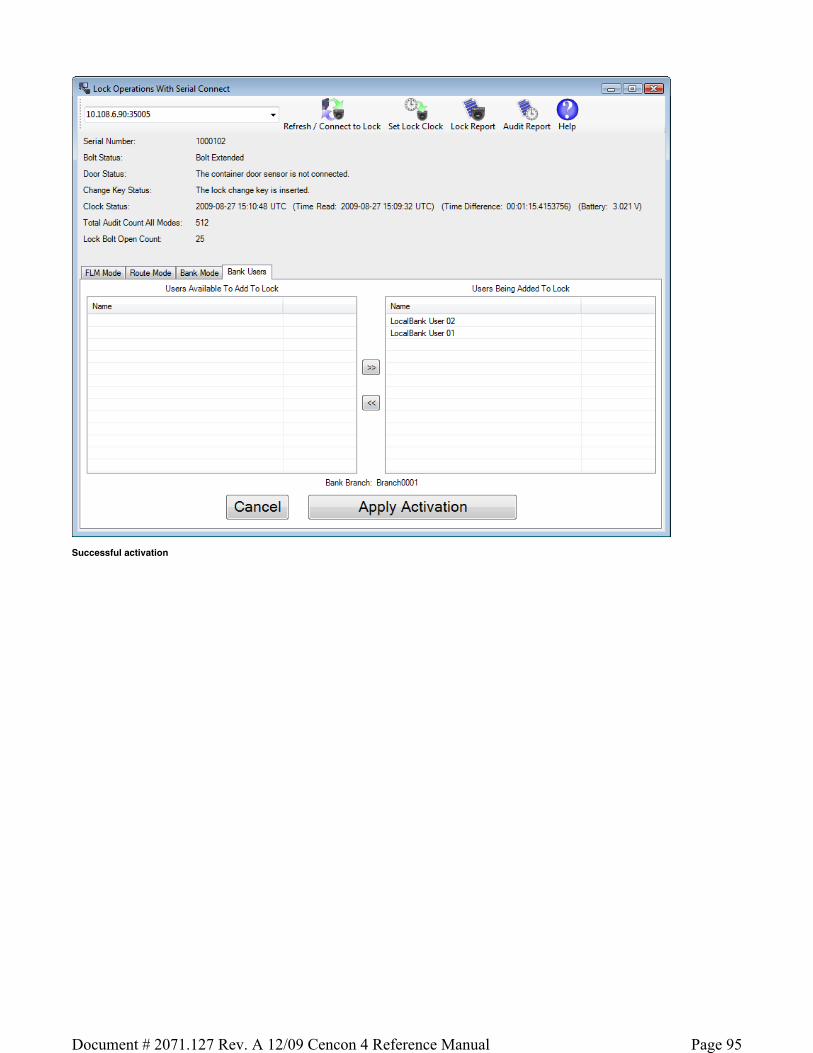
Successful activation
Page 95Document # 2071.127 Rev. A 12/09 Cencon 4 Reference Manual

The lock Bank mode is now active, and users assigned to the Bank mode lock can change their combinations and open it.
3.1.7.12 Lock Operations with Serial Connect - Shelve Bank Mode
Bank Shelve
To shelve the attached lock in Bank mode:
Select the Bank Mode tab on the Serial Connect form. Press the Shelve button. Press OK when asked if you are sure you want to shelve the lock.
Note
Once you have shelved a lock mode using the serial connection to the lock, you can not reactivate the lock mode without having physical access to the back of the lock to insert a change key. This is because the security of the serial communications for a mode being activated is set up during activation of the lock mode. When shelving a mode, that security for the mode is already set up. You can shelve a mode remotely, however you must have physical access to the inside of the lock container to insert in a change key into the back of the lock to reactivate the lock.
Initial form for active Bank mode:
Page 96Document # 2071.127 Rev. A 12/09 Cencon 4 Reference Manual

Prompt for shelving Bank mode:
Successful Shelve:
Page 97Document # 2071.127 Rev. A 12/09 Cencon 4 Reference Manual

The lock Bank mode has been shelved.
3.1.7.13 Lock Operations with Serial Connect - Resynchronize Users for Bank Mode
Resynchronize Users for Bank Mode
This operation reads the current user table of the lock and updates the Cencon database entry for the lock to match. It will ensure that the Cencon database matches the lock in the case of having to recover from a backup of the database.
To resynchronize dispatching for the the attached lock in Bank mode:
Select the Bank Mode tab on the Serial Connect form. Press the Resync Users button.
Note
If a user that is assigned access to the bank mode lock is not in the Cencon database, that user can not be resynchronized as having access in the Cencon database. This might occur if the database had to be recovered from a backup that did not have the users set up yet. It could also occur if the users were removed from the lock by key, the users deleted from the Cencon database, and the remove user key was never used at the lock. If this occurs, you will need to add the users back to the Cencon database and then resynchronize the bank mode lock user table with the Cencon database again.
Initial form for active Bank mode:
Page 98Document # 2071.127 Rev. A 12/09 Cencon 4 Reference Manual

Successful resynchronization of the Cencon database with the lock:
Page 99Document # 2071.127 Rev. A 12/09 Cencon 4 Reference Manual

The lock Bank mode user table has been resynchronized.
3.1.7.14 Lock Operations with Serial Connect - Set Access Between Single and Dual User for Bank Mode
Set Access Between Single and Dual User for Bank Mode
This operation sets the lock between needing a single user or needing dual users to open the lock, and also updates the Cencon database as needed.
To set access between single and dual users for the the attached lock in Bank mode:
Select the Bank Mode tab on the Serial Connect form. Press the Set Access button. Select the type of access required between single and dual user to open the lock. Press the Set Access button.
Page 100Document # 2071.127 Rev. A 12/09 Cencon 4 Reference Manual

Note
You can not change single or dual user access while a call is dispatched to the lock. You will need to wait until the call has been completed first. After the call has been completed, you will be able to change the access between single and dual user required.
Initial form for active Bank mode:
Form for selecting single or dual user mode access on the lock:
Page 101Document # 2071.127 Rev. A 12/09 Cencon 4 Reference Manual

The lock Bank mode has been set between single and dual user mode.
3.1.7.15 Lock Operations with Serial Connect - Set Time Delay and Open Time Window for Bank Mode
Set Time Delay and Open Time Window for Bank Mode
This operation sets the time delay period after a bank mode user enters their combination and presents their key to the lock for the user to be able to actually open the lock. This operation also sets the time window that the user can open the lock once the time delay period has elapsed. The option to set a time delay before opening and a time window to open is available only to Bank mode.
To set the time delay and open time window for the the attached lock in Bank mode:
Select the Bank Mode tab on the Serial Connect form. Press the Set Delay button. Enter the desired time delay and open time window. If a time delay value of 0 is entered, then the lock is allowed to open immediately. Press the Set Open Delay button.
Initial form for active Bank mode:
Page 102Document # 2071.127 Rev. A 12/09 Cencon 4 Reference Manual

Form for entering the time delay and open time window for the lock:
Page 103Document # 2071.127 Rev. A 12/09 Cencon 4 Reference Manual

The lock Bank mode time delay and open time window has been set.
3.1.7.16 Lock Operations with Serial Connect - View Bank Mode Users
View Bank Mode Users
To view the bank users assigned to the attached lock:
Select the Bank Users tab on the Serial Connect form. The display shows the users currently assigned to the lock.
Note
This tab displays the users currently assigned to the Bank mode lock based off of the Cencon database. If the Cencon database is not up to date with the lock, then you can resynchronize the Cencon database with the lock using the Resynchronize Users for Bank Mode operation.
Form displaying the current users for the Bank mode lock:
Page 104Document # 2071.127 Rev. A 12/09 Cencon 4 Reference Manual

3.1.7.17 Lock Operations with Serial Connect - Add Bank Mode Users
Add Bank Mode Users
To add bank users to the attached lock:
Select the Bank Users tab on the Serial Connect form. The display shows the users currently assigned to the lock. Select the Add Users button on the Bank Users tab. The display shows the form for adding users to the lock. Select which users you want to add to the lock from the list of available users. Select the Apply Adding Users To Lock button on the Bank Users tab. The selected users will be added to the lock.
Note
This tab displays the users currently assigned to the Bank mode lock based off of the Cencon database. If the Cencon database is not up to date with the lock, then you can resynchronize the Cencon database with the lock using the Resynchronize Users for Bank Mode operation.
Form displaying the current users for the Bank mode lock:
Page 105Document # 2071.127 Rev. A 12/09 Cencon 4 Reference Manual

Form used to select users to add to the Bank mode lock:
Page 106Document # 2071.127 Rev. A 12/09 Cencon 4 Reference Manual

3.1.7.18 Lock Operations with Serial Connect - Delete Bank Mode Users
Delete Bank Mode Users
To delete bank users from the attached lock:
Select the Bank Users tab on the Serial Connect form. The display shows the users currently assigned to the lock. Select the Delete Users button on the Bank Users tab. The display shows the form for deleting users from the lock. Select which users you want to delete from the lock from the list of users assigned access to the lock. Select the Apply Deleting Users From Lock button on the Bank Users tab. The selected users will be deleted from the lock.
Note
This tab displays the users currently assigned to the Bank mode lock based off of the Cencon database. If the Cencon database is not up to date with the lock, then you can resynchronize the Cencon database with the lock using the Resynchronize Users for Bank Mode operation.
Form displaying the current users for the Bank mode lock:
Page 107Document # 2071.127 Rev. A 12/09 Cencon 4 Reference Manual

Form used to select users to delete from the Bank mode lock:
Page 108Document # 2071.127 Rev. A 12/09 Cencon 4 Reference Manual

3.1.7.19 Lock Operations with Serial Connect - Set Lock Clock and Time Zone Daylight Savings Time Table
Set Lock Clock and Time Zone Daylight Savings Time Table
This operation sets the time in the lock, based off of the time on your host computer. If one or more modes are active, this will also set the daylight savings time transition table for each mode based off of the selected time zone. A form will be displayed to select the time zone for each authorized active mode.
To set the clock and time zone daylight savings time tables for the lock modes:
Select the Set Clock button on the Lock Operations with Serial Connect toolbar. If any modes of the lock are active, then a dialog displaying the time zone selection to make for each mode is displayed. Select the time zones for the different modes as needed, and then press the Set Clock And Daylight Savings Time Tables button. If the lock is shelved, only the clock will be set. If the lock has modes active, the clock wil be set and any modes you have authorization to set will have their daylight savings time table updated.
Note
Only the active modes you are authorized to set the time zone daylight savings time tables on will be updated. If you do not have authorization to update the appropriate active modes on the lock, or the modes on the lock are controlled by another company, you will not be able to update those modes.
Initial form for active FLM mode:
Page 109Document # 2071.127 Rev. A 12/09 Cencon 4 Reference Manual

Dialog for selecting the time zones to use to update the lock clock and time zone daylight savings time tables:
3.1.7.20 Lock Operations with Serial Connect - Create Lock Report
Create Lock Report
This operation reads the status of the lock as well as the status of each mode of the lock. It also reads the database information for each mode of the lock from the Cencon database. It then displays a report similar to the Cencon Individual Lock report but also including additional information which can only be accessed through the direct connection. This report will display the current status of the lock and information for each active mode of the lock. This report can be long, depending on the number of authorized active modes on the lock.
To create a lock report:
Select the Lock Report button on the Lock Operations with Serial Connect toolbar. A report of the status of the lock will be displayed.
Note
Only information for the lock modes that your company controls will be displayed. If your company does not control any of the active lock modes on the lock, then you will not be able to display any of the mode information for that lock.
Initial form for active FLM mode:
Page 110Document # 2071.127 Rev. A 12/09 Cencon 4 Reference Manual

Lock Report:
Page 111Document # 2071.127 Rev. A 12/09 Cencon 4 Reference Manual

3.1.7.21 Lock Operations with Serial Connect - Create Lock Audit Report
Create Lock Audit Report
This operation reads the status of the lock as well as the audit trail of the lock. It then displays a report similar to the report from a supervisor audit key, however there is no size restriction on the number of audits. This report can be long, depending on the number of audits on the lock.
To create a lock audit report:
Select the Audit Report button on the Lock Operations with Serial Connect toolbar. A report of the audit trail from the lock will be displayed.
Note
If the lock has one or more modes active and your company does not control any of the active lock modes on the lock, then you will not be able to download
Page 112Document # 2071.127 Rev. A 12/09 Cencon 4 Reference Manual

audit information from the lock.
Initial form for active FLM mode:
Lock Audit Report:
Page 113Document # 2071.127 Rev. A 12/09 Cencon 4 Reference Manual

Page 114Document # 2071.127 Rev. A 12/09 Cencon 4 Reference Manual

3.2 User Report
This function displays a report containing functions for maintaining the users on your Cencon system.
Under Users, click on User Operations. The following search dialog is displayed:
The Ranges tab:
Enter optional values to search for particular users and press Search to display the User Report. Note that the search process automatically swaps date start
Page 115Document # 2071.127 Rev. A 12/09 Cencon 4 Reference Manual

and end values if you accidentally enter an end date which is earlier than the start date.
If you enter a group name, you will see all users in that specific group. Check the Include All Users Who Have Access to Locks in the Specified Group Name checkbox if you also want to see all users who have access to the locks in the specified group.
Sample User Report:
Color Coding in the Report
Users who are currently dispatched to locks are displayed in the User Report with a green background.
In addition, users assigned to a DS1963 key have their User ID highlighted with a blue background.
A variety of common operations can be done with the report, to include printing, saving in various formats, and sorting the contents of the report. You can refer to these common report operations in section 3.0 Reports.
The following operations are available from the User Operations Menu:
Add a User
Add a Windows Logon User
Edit the data for the key in the reader
Display a key report for the key in the reader
Change User Information
Change Information for Multiple Users
Rename a User
Delete a User
Display Open Locks for the Selected User
Display the Bank Locks the User is Assigned To
Page 116Document # 2071.127 Rev. A 12/09 Cencon 4 Reference Manual

3.2.1 Add a User
This operation allows you to add new users to your Cencon installation.
Before Creating Users...
Depending on how you are using Cencon, certain information must be predefined so that it is available for selection during the process of creating users. This data includes:
Bank Branches: If you are going to create any Bank users you must first define the Bank Branches to which they will be assigned using the Bank Branch Report.
User Types: If want to assign a customized authorization role to any new users, you need to create the new user roles before creating the users. See User Authorization for more information.
Region Definitions: If you are going to use Region control, you should first define your regions using the Region Report.
Customer ID: If you are going to assign a Customer ID to your users you should first define the Customers using the Customer Report.
To add a New User, complete the following steps from the User Report:
1. Select Operations and click on Add a New User. The Add a New User window is displayed:
The second tab of the dialog allows you to set up time restrictions and frequency of use limitations:
Page 117Document # 2071.127 Rev. A 12/09 Cencon 4 Reference Manual

2. Enter a name for the User (maximum of 64 characters).
Caution
User names are very critical in the Cencon System. They are case sensitive and can be up to sixty-four (64) characters in length. However, if you are using Centran 2 in conjunction with your Cencon system, you need to consider that the Centran User name field is limited to 20 characters.
Suggested User IDs
Using "Bill" as a name is valid, however, you may have more than one "Bill" in your organization. Using "98709003" as a user ID is also valid but may get confusing especially when one or more numbers gets out of order when we do not read them correctly. Additionally, in dispatching a person we know as "Bill" using the number "98709003" as the user ID can also be confusing. It is suggested that user IDs be alpha or alphanumeric. It is also suggested that you use "Nicknames". For example, a user can be identified as "FLM1" and use "Bill N" in the Nickname field. Another example could be a user identified as "Tom1" and use "Fleming" (last name) in the Nickname field. Spaces are allowed in ID fields so "Bill Jones" is valid. However you choose to identify users, some thought should be given to it before you begin.
3. Use of the Nickname field is optional. Enter a Nickname for the User if desired.
Caution
Nickname can be up to sixty-four (64) characters in length. However, if you are using Centran in conjunction with your Cencon system, you need to consider that the Centran Nickname field is limited to 10 characters.
4. For User Type, select the appropriate type from the drop-down list box. If you select Bank as the user type, additional bank specific fields are displayed:
Page 118Document # 2071.127 Rev. A 12/09 Cencon 4 Reference Manual

Bank Branch Select the branch to which the user should be assigned.
Bank User ID Enter a numeric value for the user's Bank User ID. This value must be unique within the Bank Branch.
Bank Combination The default bank user combination is "50 25 50". If you want to change the default for this user, enter the six digits of a new combination.
Combination must be changed at the lock Select this check box if you want to require that the user change their combination the first time the key is used at the lock.
5. For User Password, enter a password for the User. For a logon user, this password will be used for logon to Cencon in conjunction with the user key. The software logon keys (i.e. Dispatcher, Supervisor, Special Supervisor) require a password to be set for logon. For lock user keys (i.e. FLM, Route, or Bank), the password is optional.
Note
For FLM/RSP Users, the password is stored in the User ID table without encryption, for use by third-party systems working with Cencon or Centran. Cencon Logon users (i.e. Dispatchers, Supervisors, Special Supervisors) passwords are encrypted in the User ID table and are not accessible by third-party systems.
6. If you are using Lock Groups, fill in the Group ID or a partial group identification for the locks that this user should be able to access.
Group ID Usage
If you have Group IDs enabled, you will be able to enter a group ID for a new FLM/RSP user. The user will be restricted to being dispatched to locks that have a group ID that begins with the same series of characters as the group ID of the user, or to locks that do not have a group ID set.
Example: Let's say that there have been several locks with Group IDs created that that all begin with the characters "RED". Another set of locks with Group IDs has been created that all begin with the characters "BLUE". Then, for a particular FLM or RSP, you can grant security access for all locks that have a Group ID that begins with the characters "RED" by specifying a partial Group of "RED" for the user. I.E, that user could access group IDs "RED12", "RED13" and "RED14", but could not access group IDs "BLUE12", "BLUE13" and "BLUE14".
7. Access Control - The group of fields on the Access Control tab are used to define a time slot, or a series of time slots, during which the user is authorized to operate Cencon locks. If this group of fields is left blank, the user will have unrestricted time access to the locks. Otherwise, users can be assigned time windows in which they have authorized access to the locks. There can be different times for different days of the week or multiple windows on particular days. Up to three sequences of days and times can be entered for each user. You may also specify that the user is only authorized for limited number of dispatches or within a specified date range.
Warning
If you define time access windows for your system users, be sure to take into consideration time orientation changes if applicable (i.e., Standard Time to Daylight Savings and vice versa). Your PC system will automatically adapt for these time changes, but the time windows carried in the keys will be off by an hour when your PC system goes to a different time orientation. To alleviate this problem, you can have a +1 hour and -1 hour allowance in your time window. If security measures will not tolerate this type of allowance in the window, each user's key must be brought back to the system for updating when the time changes. The function in the PC Software that is used to update the time windows in the keys is Change A User ID and is found on the User ID/Key Maintenance Menu under the Special Supervisor's functions. For more detail see the following section on Change A User ID.
Caution
If you are using the time window capabilities of the system and you have a centralized dispatch center, keep in mind that accommodations will have to be made when adding FLM and Route Personnel to the system whose keys will be distributed to different time zones. The Window Opening Information will have to be adjusted by the difference (+/-) between the dispatch center and the time
Page 119Document # 2071.127 Rev. A 12/09 Cencon 4 Reference Manual

zone where the key will be sent.
There are three fields used to define the user's access windows.
Days Window in Effect
This defines which days of the week the user is authorized to open locks. It can be from one to all seven days. Place the cursor on each box you want to select and press the spacebar to select that day or just click on the box with the mouse pointer.
Start Time
This is the time the authorization time slot starts.
Duration
This field is the length of the time period (in hours and minutes) that the user is authorized to access the locks. This is not the "end time" for the authorized access period.
Dispatches Allowed
This field limits the number of times the user may be dispatched to a lock. The user is disabled from further dispatches when this limit is reached. Set to "0" to allow unlimited dispatches (the default). The user's current dispatch count is compared to the entered value. Thus, it is possible for the user to be immediately disabled if their current dispatch count (viewable on the Key Report) is greater than or equal to the entered value. This value may be changed to control future user access.
Access Limit Start and End Dates
This field specifies a date range during which the user is enabled for dispatches. If the boxes are not checked, the user is always enabled based on the time windows settings. The user is authorized beginning on the Start Date and is not authorized on or after the End Date.
Note
If the user access windows fields are left blank, the user will have unrestricted access to the lock or PC System.
8. If region control is active, and the current dispatcher is not restricted to a local region, then the region ID can be selected from a drop down list of regions. This determines what region the new user is assigned to. If the current dispatcher is assigned to a local region, then any users created by that dispatcher are automatically assigned to the same region.
Regions Usage
Region control is a method of controlling what locks and FLM/RSP IDs can be viewed or accessed by different Cencon logon users.
Regions also control which locks that FLM/RSP IDs can be dispatched to. FLM/RSP IDs can not be dispatched to locks assigned to a different region.
This is done by assigning a region ID to locks and users. A region ID is a name up to 64 characters long. There is a table of region IDs that is maintained to keep track of what regions have been defined.
There are two types of regions: Global and Local. A Cencon logon assigned to a global region can view and administer any lock and FLM/RSP ID in the system. A Cencon logon assigned to a local region can only view and administer locks and FLM/RSP IDs with the same assigned region. The type of region only affects what Cencon logon users can view. It make no difference as to how regions are used for lock operations.
Assume you have two regions: Lexington which is a global region, and Richmond which is a local region.
The following are assigned to the Lexington global region:
The following are assigned to the Richmond local region:
DispatcherLex can see and dispatch all of the locks - LockLex1, LockLex2, LockRich1, LockRich2. DispatcherLex can also see and dispatch all of the FLM/RSP IDs - FLMUserLex1, FLMUserLex2, FLMUserRich1, FLMUserRich2.
DispatcherRich can only see and dispatch the locks assigned to region Richmond - LockRich1, LockRich2. DispatcherRich can also only see and dispatch the users assigned to region Richmond - FLMUserRich1, FLMUserRich2.
The FLM IDs FLMUserLex1 and FLMUserLex2 can only be dispatched to the locks assigned to the same Lexington region - LockLex1, LockLex2.
The FLM IDs FLMUserRich1 and FLMUserRich2 can only be dispatched to the locks assigned to the same Richmond region - LockRich1, LockRich2.
9. Enter Service Branch and user full name information as desired.
Locks: LockLex1, LockLex2
FLM IDs: FLMUserLex1, FLMUserLex2
Dispatcher: DispatcherLex
Locks: LockRich1, LockRich2
FLM IDs: FLMUserRich1, FLMUserRich2
Dispatcher: DispatcherRich
Page 120Document # 2071.127 Rev. A 12/09 Cencon 4 Reference Manual

10. Insert the key to be assigned to the User into the Key Reader. 11. Click on Process to process the entered information. The following window is displayed to confirm the user creation and to allow creation of another user.
Click on Yes to return to the Add User window. To enter additional Users, repeat the above steps until all desired Users are added.
12. Click on No to return to the User Report.
3.2.2 Add a Windows Logon User
This option allows you to add a new Windows User to your Cencon system. To add a Windows User, complete the following steps from the User Report's Operations menu:
1. Click on Add a Windows Logon User. The following window is displayed:
You can search for existing users registered on your network with your current Windows logon domain. To do this, click the Search/Refresh User List button.
The data field is populated with users registered on your network. There may be a noticeable time delay while this data is being displayed depending on the network access speed and the number of users. You can enter a name or partial name and then select to search for entries matching that name. Only the name will be used in the search. The domain searched for is always your current Windows logon domain. If you leave the entered name blank, you will get all users for the current domain.
Page 121Document # 2071.127 Rev. A 12/09 Cencon 4 Reference Manual

Note
Depending on the number of users on your network and the number you wish to add as Cencon users, it may be more efficient to export all active users to a spreadsheet and create a SQL script to import them to Cencon. Contact Kaba Mas technical support for assistance.
The following is an example of searching for a name or partial name from the current Windows logon domain:
2. Select a user name from the list. 3. The User Information and Access Control data is created in the same manner as the Add a User procedure.
3.2.3 Change User Information
This option allows you to change the information for an existing User.
To change information on a user, complete the following steps from the User Report:
Select a user by clicking on the row for that user.
Right-click on the highlighted row, and select Change User Information. The "Edit User" window is displayed for the selected user ID.
The User Information and Access Control data is modified in the same manner as for the Add a User procedure.
3.2.4 Change information for Multiple Users
Page 122Document # 2071.127 Rev. A 12/09 Cencon 4 Reference Manual

This option allows you to select multiple users in the User Report and change a subset of the user data for all the selected users.
To change information on a group of users, complete the following steps from User Report menu:
1. Highlight users by holding down the Control key and clicking the rows of the selected users. 2. Right-click on the selected group, and choose Change Information for Multiple Users as in the following example:
The following dialog opens:
3. Edit the data. For more information on these fields, refer to 3.2.1 Add a User. Note that the new data will replace the existing data for all the selected users.
4. Click on Update All Selected Users to process the entered information. In this example, Cencon will update the Service Branch and Region for all the selected users. A confirmation message similar to the following is displayed:
3.2.5 Rename a User
This option allows you to change a user's name.
Page 123Document # 2071.127 Rev. A 12/09 Cencon 4 Reference Manual

To rename a user, select a user in the User Report and then press Rename a User in the Operations menu. The following dialog displays some of the data for the selected user and allows you to enter a new name:
Click on Rename to update the user.
3.2.6 Delete A User
This option allows you to delete a User from the system.
Note
You cannot delete a user if there are open locks assigned to that user.
Select a user in the User Report and then click on Delete a User. The "Delete a User" window displays the user's name and asks for verification of the deletion:
Note
If the user's key is in the reader, it is erased as part of this operation. If you later perform a Restore User operation from the User History Report and do not have the key inserted at that time, the key may be unusable because the necessary security information and the time widows are not restored.
Insert the user's key and press OK. If you do not insert the user's key, the user is deleted from Cencon but the information on the key is not reset, as in the following:
3.2.7 Display Open Locks for the Selected User
This function is used to display a report of the locks dispatched to the selected user.
Select a user in the User Report and then select Display Open Locks for the Selected User from the Operations menu. This automatically opens the Lock Operations Report to display only those locks open for the selected user. See Lock Operations Report for details on that report.
Page 124Document # 2071.127 Rev. A 12/09 Cencon 4 Reference Manual

3.3 Customers
This function allows you to add new customer data records, update existing records, delete a record, or find a record.
Cencon provides no processing functions for the Customer Data other than to maintain the data table and to display the data stored there. The data items have labels that imply the type of data stored but Cencon does not impose any limitations or validity checks to the data.
To create or maintain Customer Data, select Customer Report from the main Cencon Window. The Search Customers window allows you to specify information for searching for particular customers:
The Customer ID field may be searched either for an exact match or for a value containing the entered text, depending on the "Return exact matches for the Customer ID." checkbox. The Customer Number is only searched for an exact match. All other fields are searched for values which contain the entered search text.
Sample Customer Report:
A variety of common operations can be done with the report, to include printing, saving in various formats, and sorting the contents of the report. You can refer to these common report operations in section 3.0 Reports.
The following operations are available from the Customer Report Operations Menu:
Add a Customer Select this operation to open the Add a Customer window:
Page 125Document # 2071.127 Rev. A 12/09 Cencon 4 Reference Manual

Change Customer Information Select a user and then the Modify a Customer operation to open the edit window:
Delete a Customer This function deletes the selected customer.
Display Open Locks for a Customer This function is used to display a report of the locks dispatched to the selected customer. Select a customer in the Customer Report and then select Display locks for the selected customer from the Operations menu. This opens the Lock Operations Report, automatically filtered to display the open locks for the selected user. See Lock Operations Report for details on that report.
Map the Selected Customer Locations Cencon provides the ability to send customer address information to external mapping software. Cencon Version 4 supports the following software:
Microsoft MapPoint 2006. MapPoint is a commercially available product and is not included in the Cencon 4 software package. MapQuest - a free internet mapping service (an active internet connection is required).
Use the Preferences dialog (on the main Cencon window) to select the desired mapping software.
Mapping Considerations...
Mapping applications require accurate location information. In addition, MapQuest requires that the state/province name be the standard two character abbreviation.
To display customer locations on a map, select one or more customers from the Customer Report and then choose Map the selected Customer Locations.
If the address information appears to be sufficient to locate the customer, Cencon passes the data to the mapping program for display. Refer to the mapping software's documentation for information on using the specific mapping product.
Page 126Document # 2071.127 Rev. A 12/09 Cencon 4 Reference Manual

3.4.1 Activity Log Report
This report lists the information in the Cencon activity log. The following Search screen is displayed prior to generating the report to allow filtering for specific activity records:
Sample Activity Log report:
Note that lines in the report associated with failures are highlighted. For instance, attempts to dispatch a lock that is already open, attempting to enter the wrong close seal to close out a lock, trying to dispatch a key that does not exist in the Cencon System database, etc, would be highlighted as failed events in the activity log.
The only Operation for this report is Archive. Selecting Archive opens the following window:
Page 127Document # 2071.127 Rev. A 12/09 Cencon 4 Reference Manual

Enter the number of days for the archive and press OK. The records are copied to the Activity Log Archive and removed from the Activity Log.
3.4.2 Archived Activity Log Report
This report lists the archived activity data. It has the same initial search screen and data presentation as the List Activity Log report.
There are no Operations for this report.
Sample report:
3.4.3 Lock Log History Report
This report lists a history of the lock closing data. Each time a lock is closed, the record from the Open Locks data table is moved to the Lock Log History data table. Thus, the two reports have the same initial search screen and report format. See the List Open Locks report for more information.
Sample report:
Page 128Document # 2071.127 Rev. A 12/09 Cencon 4 Reference Manual

The only Operation for this report is Archive. Selecting Archive opens the following window:
Enter the number of days for the archive and press OK. The records are copied to the Lock Log History Archive and removed from the Lock Log History.
3.4.4 Lock Log History Archive Report
This report lists the archived Lock Log History data. It has the same initial search screen and data presentation as the List Open Locks report and the Lock Log History report.
There are no Operations for this report.
3.4.6 User History Report
The User History Report is used to display sets of user records from the Cencon System User ID History database table. It does this based on the search criteria that you specify, for which records you want displayed.
Explanation For The User ID History Table
The User History table maintains a record of who was previously using a key, and the time period that they were assigned to the key.
This allows audit dumps from locks to correctly show the user name according to who was using a key at the time the event occurred.
If you rename what user has a certain key, then there needs to be a way to look up whether it was the old user or the new user that did an activity at a lock. This is based off of the time of the event. If the event occurred prior to the starting date for the current user of the key, then the key and date is compared against the User History Log table. The user from the key's history is displayed if that person was assigned to the key when the event occurred.
Additionally, if the key is no longer in the User table because the user was deleted from the system, then there needs to be a way to look up the key for displaying lock audit events that occurred prior to that person being deleted. In this instance also, where the key can't be found in the User table, the key is looked up in the User History Log table.
The following search dialog appears for the User History Report, if the User History Report is not already open. If the User History Report is already open, then it remains with it's previous contents.
Page 129Document # 2071.127 Rev. A 12/09 Cencon 4 Reference Manual

This search dialog allows you to specify search criteria for which users you want to have displayed by the report. The "Fields" tab is shown above.
The search dialog also has a check box to allow you to select if you want the search settings you enter to be saved for next time you open the report. This also specifies that you want the sort settings to be saved for the report. If this checkbox is not selected, then your previous search settings will not be restored next time you open the report.
There are additional search settings on the "Ranges" tab of the search dialog. This is displayed by clicking on the "Ranges" tab.
This tab allows you to select to search by certain ranges of values. This includes being able to specify a range of combinations currently issued to the user, and ranges of dates for the creation, deletion, and last used date of the user.
Page 130Document # 2071.127 Rev. A 12/09 Cencon 4 Reference Manual

Once you are satisfied with the search criteria that you want for the User IDs, click on Search to display the result of the search. The report is displayed as follows:
Note
The User ID History report has the deletion date field set for the users. This is different from the User ID report, where this field will always be blank.
Depending on the number of records resulting from the search, the report may take some time to finish loading records. You can still conduct operations, close the report, etc, while the report is still loading records. While the report is loading records, a status indicator at the bottom of the report will display Loading in red. Once the report finishes loading records, this indicator will change to green and show Done.
If the number of records resulting from the search are too big to fit safely into local memory, then the report status indicator will display in yellow Partial. If this occurs, you can still look at the entire results of the report, but not all of it can be stored locally at the same time. The report will fetch and unload records as needed to display the section of the report you scroll to. The status bar at the bottom of the report will indicate your position in the report and the number of records currently in memory.
A variety of common operations can be done with the report, to include printing, saving in various formats, and sorting the contents of the report. You can refer to these common report operations in section 3.0 Reports.
The operations menu provides access to a set of operations unique to the User History Report.
Archive Report
Selecting Archive opens the following window:
Enter the number of days for the archive and press OK. The records are copied to the User History Archive and removed from the User History.
Reactivate User
Selecting Reactivate User restores the selected user (or users) to Cencon. If the user's key is on the reader and the user has time windows defined, the time windows are written to the key. The following message indicates successful restoration of a deleted user:
3.4.7 Archived User History Report
The Archived User History Report is used to display sets of user records from the Archived User History database table. It does this based on the search criteria that you specify, for which records you want displayed.
The following search dialog appears for the Archived User History Report, if it is not already open. If the Archived User History Report is already open, then it remains with it's previous contents.
Page 131Document # 2071.127 Rev. A 12/09 Cencon 4 Reference Manual

This search dialog allows you to specify selection criteria for the users you want to have displayed in the report. The "Fields" tab is shown above.
The search dialog also has a check box to allow you to select if you want the search settings you enter to be saved for next time you open the report. This also specifies that you want the sort settings to be saved for the report. If this checkbox is not selected, then your previous search settings will not be restored next time you open the report.
There are additional search settings on the "Ranges" tab of the search dialog.
This tab allows you to select to search by certain ranges of values. This includes being able to specify a range of combinations currently issued to the user, and ranges of dates for the creation, deletion, and last used date of the user.
Page 132Document # 2071.127 Rev. A 12/09 Cencon 4 Reference Manual

Once you are satisfied with the search criteria that you want for the Users, click on Search to display the result of the search. The report is displayed as follows:
Note
The Archived User History report has the deletion date field set for the users. This is different from the User ID report, where this field will always be blank.
Depending on the number of records resulting from the search, the report may take some time to finish loading records. You can still conduct operations, close the report, etc, while the report is still loading records. While the report is loading records, a status indicator at the bottom of the report will display Loading in red. Once the report finishes loading records, this indicator will change to green and show Done.
If the number of records resulting from the search are too big to fit safely into local memory, then the report status indicator will display in yellow Partial. If this occurs, you can still look at the entire results of the report, but not all of it can be stored locally at the same time. The report will fetch and unload records as needed to display the section of the report you scroll to. The status bar at the bottom of the report will indicate your position in the report and the number of records currently in memory.
A variety of common operations can be done with the report, to include printing, saving in various formats, and sorting the contents of the report. You can refer to these common report operations in section 3.0 Reports.
There are no operations for this report.
3.4.8 Archived Route Report
This report lists the archived routes.
The only Operation for this report is the ability to restore an archived route. The Restore function fails with an error if any of the archived route locks are not in the Cencon database.
Sample report:
3.5.1 Initialize Audit Download Key
This option allows you to prepare a Supervisor Audit Key for use in auditing a Lock. To initialize an SA Key, insert an SA Key into the key reader and click on Initialize Audit Download Key in the main Cencon window. The following is displayed:
Page 133Document # 2071.127 Rev. A 12/09 Cencon 4 Reference Manual

If the key will be used to access the audit data from a Bank Mode lock, click on the check box and select the lock's Bank Branch name as in the following:
Click on Initialize Key to perform the initialization.
Caution
To retrieve an audit from a Lock, you must always initialize the SA key first. Failure to do so could cause unpredictable results in your audit.
The Display Key Report button opens the Key Report for the key in the reader.
See Retrieve Audit Download From Lock for details on using the key at the lock.
3.5.2 Initialize Lock User Key Clock
The historic (current) FLM, Route, and Bank mode Lock User keys (utilizing iButton types DS1994 and DS1427) have an internal clock that is used by the lock to time stamp lock operations (Gen1). The clock in the key is set to GMT by using the time in your PC and the GMT offset. If you request a key report on a Lock Key and notice the time is not correct, you should use this menu to reset the clock in the key.
Note
This process does not need to be performed to update the time in the keys for a change to Daylight Savings Time or back to Standard Time. The Cencon PC System will automatically accommodate for that type of time change when reading the audit times for a user key.
To initialize the clock in a Lock Key, insert a lock Key into the key reader and click on Initialize Lock User Key Clock in the main Cencon window. The following is displayed:
Click on Initialize Key Clock. A confirmation message is displayed:
Page 134Document # 2071.127 Rev. A 12/09 Cencon 4 Reference Manual

The Display Key Report button opens the Key Report for the key in the reader. The Read Key button is used to reread the key in the reader if you change keys.
Note
An alternative method of updating the time in keys is by using the Key Maintenance Utility (KMU). For more information on the KMU see the Kaba Mas web site at: www.kabamas.com
3.5.3 Reinitialize a User Key
This function can be used to reinitialize a key that did not initialize properly or to reinitialize a key that has been used in another system.
Caution
This operation deletes the key's audit data.
To reinitialize a user key, insert the key into the key reader and click on Re-initialize User Key in the main Cencon window. The following is displayed:
Click on Re-Initialize User Key. A confirmation message is displayed:
The Display Key Report button opens the Key Report for the key in the reader. The Read Key button is used to reread the key in the reader if you change keys.
3.5.4 Key Report
This function displays a report on the data in a key. To report on the data in a key, insert the key into the key reader and click on Key Report in the main Cencon window. Cencon determines the key type and displays a report which is customized for that type. The following is a sample report for an FLM type user key:
The top of the Key Report displays basic information about the key:
Page 135Document # 2071.127 Rev. A 12/09 Cencon 4 Reference Manual

The center of the Key Report displays information on the key's user from the Cencon database:
The bottom of the Key Report displays audit data from the key:
Page 136Document # 2071.127 Rev. A 12/09 Cencon 4 Reference Manual

User Key Times
The Close times from lock user keys are only accurate within plus or minus 32 seconds. If more exact times are desired, use the times from a lock audit.
For example, the open and close times for the second event in the above screen image are both 2009-07-06 13:35:47. This is the result of an open and close occurring less than 32 seconds apart.
Lock Audit Report Details
The following section of the lock audit report provides details as the current activation status of the lock:
Note the "User" items which indicate the key(s) used to open the lock to perform the activation:
The first line has "Not Set" for both User Key 1 ID and User Key 2 ID. Since FLM mode was the first mode activated on the lock, the Factory Combination was used for the initial opening and no key was required. The second line indicates that Bank mode was activated at a later time. The key "00000030D922", user ID "f" was used to open the lock to start the Bank activation procedure. If the FLM mode had been "dual", two FLM keys would have been required and there would be an entry under User Key 2 ID also.
The following table provides descriptive information for the lock audit.
Transactor Audit Transaction Description
LockConsecutive Failed Attempts Limit (NOTE: in previous software versions, audit was shown as "3/5 Attempts")
Beginning of a lock out (LCO) due to 5 repeated incorrect factory combos, incorrect FLM, Route, or Bank user combos, or incorrect bank user combos presented when changing combo. See "Troubleshooting Single Lighting Bolt."
Lock Silent Alarm Reset Duress alarm is found on from a previous operation. Last opening added 1 to the 5th digit of the combination.
Lock Clock Set Key Used A white Clock Set key was used at the lock
Lock Clock Reset Indicates clock reset to 1/1/2000 12:00:00 AM due to loss of or surge of battery power due to an external event.
Lock Factory/Shelved Mode Open The lock was opened with the factory/shelved mode combination
Lock Factory/Shelved Mode Closed The bolt was extended after an opening with the factory/shelved mode combination
Page 137Document # 2071.127 Rev. A 12/09 Cencon 4 Reference Manual

3.5.5 Initialize Lock Time Set Key
Cencon Gen 2 locks have an internal clock that is used by the lock to control entry and to create time stamps for lock operations. The time in the lock is set to GMT using the white DS1922 key which has been initialized by Cencon to the time in your PC.
Note
To insure accurate time in your locks:
Check that the time on your PC is correct when initializing the DS1922 key. Since the clock in the DS1922 key has a known drift of about 2 minutes a month, you should plan to reinitialize time set keys regularly.
Lock Factory/Shelved Mode Combo Changed The lock factory/shelved mode combination was changed
FLM*/Route*/Bank* Open Only Lock opening by user key in the listed mode (or 1 of the 2 users in dual mode)
FLM*/Route*/Bank* Close Only initial close seal retrieval by a user key if the last audit record written was not an opening by this same user key
FLM*/Route*/Bank* Open/Close A consecutive open and a close record by the same user key
FLM*/Route* Close seal retrieval Subsequent close seal retrieval by FLM or Route user key (#4)
FLM/Route Resync Combo State A resync key was used to resynchronize the listed mode's combo state with the PC software
FLM/Route/Bank Time Zone And DST Transition Table Updated
A clock set key was used to update the time zone information and DST transition table for the mode
Bank Change Combo Bank user key changed combination
* These records also show up as audits on the F, R, or B user key.
SA Key Audit Download Valid SA audit download key presented ("Aud")
SA Key Initialize FLM (or Route or Bank) Mode listed was activated; added to main audit trail in Gen2 ("InI")
SA Key Shelve FLM (or Route or Bank) Mode listed was shelved (deactivated); added to main audit trail in Gen2 ("ShL")
SA Key Add User Add Bank mode users to the user table ("Add")
SA Key Delete User Delete Bank mode users from the user table ("dEL")
SA Key Bank User Table Download Bank user table downloaded to SA key ("udP")
SA Key FLM (or Route or Bank) Update Activation The activation was updated from Compatibility mode to full Gen2 mode for the listed mode ("UPA")
External Sensor Door Open Door found open when checking for closed door (after bolt gets extended and lock powered up.)
External Sensor Remote Disable Asserted Remote disable signal found asserted when lock was powered up.
Serial (Shelved Mode) Clock Write The lock clock was anonymously updated via serial communications (if no modes active)
Serial (Shelved Mode) Activate FLM (or Route or Bank) Mode Listed mode was activated via serial communications while the lock was in Factory/Shelved mode
Serial (Kaba Mas) Clock Write Kaba Mas updated the lock clock via serial communications
Serial (Kaba Mas) Factory Reset FLM (or Route or Bank) Mode Mode was shelved via serial communications by Kaba Mas
Serial (FLM, Route or Bank) Clock Write Listed mode updated the lock clock via serial communications
Serial (FLM, Route or Bank)
Time Zone And DST Transition Table Updated
Listed mode's time zone info and DST transition table were updated via serial communications
Serial (FLM, Route or Bank)
Access Configuration (Single/Dual) Written Listed mode's access configuration (single user access / dual user access) was changed via serial communications
Serial (FLM, Route or Bank)
Confirm Close The mode's close seal (or close confirmation) was retrieved via serial communications that had not yet been obtained by a key in that mode.
Serial (FLM, Route or Bank) Shelve Mode Listed mode was shelved via serial communications
Serial (Bank) Users Added Bank mode users added via serial communications
Serial (Bank) Users Deleted Bank mode users deleted via serial communications
Serial (Bank) Time Delay Configuration Written Bank mode time delay configuration was changed via serial communications
Page 138Document # 2071.127 Rev. A 12/09 Cencon 4 Reference Manual

Note
This process does not need to be performed to update the time in the lock for a change to Daylight Savings Time or back to Standard Time. The lock automatically accommodates for that type of time change.
To initialize a time set key, insert the white DS1922 Key into the key reader and click on Initialize Key to Set Lock Time in the main Cencon window. The following is displayed:
The Display Key Report button opens the Key Report for the key in the reader. The Read Key button is used to reread the key in the reader if you change keys.
The Key information box displays the current time zone and time from the key. The Set Time Zone To selection defaults to the time zone set on the PC.
To initialize a key, select the desired time zone and press the Initialize Key button. A confirmation message is displayed:
See Set the Lock Time for details on using the time set key.
3.5.6 Create a Retrieve Bank Users Key (Gen2)
To retrieve the list of bank users assigned to a Gen 2 lock, insert a red SA Key into the key reader and click on Create a Retrieve Bank Users Key (Gen2) in the main Cencon window. The following is displayed:
Click on Initialize Key. A confirmation message is displayed. To use this key at a lock, see Retrieve Bank Users From Lock.
The Display Key Report button opens the Key Report for the key in the reader. The Read Key button is used to reread the key in the reader if you change keys.
Page 139Document # 2071.127 Rev. A 12/09 Cencon 4 Reference Manual
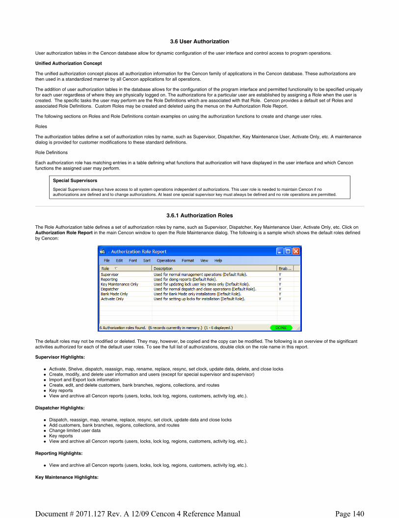
3.6 User Authorization
User authorization tables in the Cencon database allow for dynamic configuration of the user interface and control access to program operations.
Unified Authorization Concept
The unified authorization concept places all authorization information for the Cencon family of applications in the Cencon database. These authorizations are then used in a standardized manner by all Cencon applications for all operations.
The addition of user authorization tables in the database allows for the configuration of the program interface and permitted functionality to be specified uniquely for each user regardless of where they are physically logged on. The authorizations for a particular user are established by assigning a Role when the user is created. The specific tasks the user may perform are the Role Definitions which are associated with that Role. Cencon provides a default set of Roles and associated Role Definitions. Custom Roles may be created and deleted using the menus on the Authorization Role Report.
The following sections on Roles and Role Definitions contain examples on using the authorization functions to create and change user roles.
Roles
The authorization tables define a set of authorization roles by name, such as Supervisor, Dispatcher, Key Maintenance User, Activate Only, etc. A maintenance dialog is provided for customer modifications to these standard definitions.
Role Definitions
Each authorization role has matching entries in a table defining what functions that authorization will have displayed in the user interface and which Cencon functions the assigned user may perform.
Special Supervisors
Special Supervisors always have access to all system operations independent of authorizations. This user role is needed to maintain Cencon if no authorizations are defined and to change authorizations. At least one special supervisor key must always be defined and no role operations are permitted.
3.6.1 Authorization Roles
The Role Authorization table defines a set of authorization roles by name, such as Supervisor, Dispatcher, Key Maintenance User, Activate Only, etc. Click on Authorization Role Report in the main Cencon window to open the Role Maintenance dialog. The following is a sample which shows the default roles defined by Cencon:
The default roles may not be modified or deleted. They may, however, be copied and the copy can be modified. The following is an overview of the significant activities authorized for each of the default user roles. To see the full list of authorizations, double click on the role name in this report.
Supervisor Highlights:
Activate, Shelve, dispatch, reassign, map, rename, replace, resync, set clock, update data, delete, and close locks Create, modify, and delete user information and users (except for special supervisor and supervisor) Import and Export lock information Create, edit, and delete customers, bank branches, regions, collections, and routes Key reports View and archive all Cencon reports (users, locks, lock log, regions, customers, activity log, etc.).
Dispatcher Highlights:
Dispatch, reassign, map, rename, replace, resync, set clock, update data and close locks Add customers, bank branches, regions, collections, and routes Change limited user data Key reports View and archive all Cencon reports (users, locks, lock log, regions, customers, activity log, etc.).
Reporting Highlights:
View and archive all Cencon reports (users, locks, lock log, regions, customers, activity log, etc.).
Key Maintenance Highlights:
Page 140Document # 2071.127 Rev. A 12/09 Cencon 4 Reference Manual

Initialize audit download key Initialize FLM, Route, and Bank key clocks Initialize key to retrieve bank users Display a key report for lock audit, Bank, FLM, and Route keys
Bank Mode Only Highlights:
Activate, Shelve, map, rename, replace, and update data for bank locks Add customers, bank branches, regions, and collections (bank related only) Create, modify, and delete bank user information and bank users View and archive all Cencon reports (users, locks, lock log, regions, customers, activity log, etc.).
Activate Only Highlights:
Activate, Shelve, dispatch, reassign, map, rename, replace, set clock, update data, delete, and close locks Create, modify, and delete user information and users (FLM, Route, and Bank only) Import and Export lock information Create, edit, and delete customers, bank branches, regions, collections, and routes Key reports View and archive all Cencon reports (users, locks, lock log, regions, customers, activity log, etc.).
The Operations menu provides access to the maintenance functions for this data:
As an example, assume you want to create a new role which only allows the user to dispatch, reassign and close FLM locks. From the Authorization Role Report, select Add Role. The Add Role dialog is displayed. Enter a descriptive Role Name ("FLM Dispatcher" for this example) and some optional descriptive text:
Press Create to add the custom role to Cencon. The new role is now displayed in the Authorization Role Report:
The next step is to assign the specific tasks users assigned to this role may perform. This is done using the Role Definition Report which opens automatically as the new role is created. To access the Role Definition Report for other roles, double click on the Role name or click on the Role and select Role Definition Listing from the Operations menu. The Role Definition Report initially contains only the Logon role (and the only available operation is Add) since the new role has not been assigned any other permitted tasks:
Page 141Document # 2071.127 Rev. A 12/09 Cencon 4 Reference Manual

Select add to open the task selector:
Since our new user is only allowed to dispatch, reassign, and close FLM locks, select the Dispatchable Lock category to display the available tasks related to dispatching locks. Then select Dispatch Lock, Reassign Lock, and Close Lock in the Operations list, followed by FLM only in the Types list for each operation selected.
Page 142Document # 2071.127 Rev. A 12/09 Cencon 4 Reference Manual

Finally, select Add Operation to assign the selected tasks to the new role. The newly defined role will now be displayed in the User Type selection list on the Add a New User form. Resultant Authorization Definition Report for the new role:
Other Authorization Role Report operations:
Edit Role Data The role edit dialog allows you to make changes to the name, description and status of the selected role:
Delete Role Delete the selected role. A verification dialog is displayed:
A role may not be deleted if there are any users assigned to it:
Page 143Document # 2071.127 Rev. A 12/09 Cencon 4 Reference Manual

Copy Role
Sample Role Copy dialog:
Enter a name for the new role and an optional description. Press Copy to create the new role and copy all the authorization definitions from the existing role to the new role:
Enable Role
Allows the role to operate normally.
Disable Role Disables all users assigned to the role such that they may not perform any Cencon operations.
Role Definition Listing This function opens the Authorization Definition Report.
3.6.2 Authorization Definitions
This report (accessed from the Authorization Role Report) allows you to manage all the operations allowed for the selected role. The following is a sample Role Definition Report for the Dispatcher role:
Page 144Document # 2071.127 Rev. A 12/09 Cencon 4 Reference Manual

For example, the above report indicates that the Dispatcher Role is authorized to change the user nickname for FLM type users and Route type users but not for any other users.
Note
The Sort and Copy operations on this report only operate on the Name and Type columns. Clicking on the Description column heading causes the report to be refreshed as unsorted.
The available operations are:
Add Use the Add dialog to add additional operations. For example, the following Add dialog gives our Dispatcher role the authorization to also change the nickname for Special Supervisors:
Note
As noted on the dialog, operations which have already been added to the current role are not displayed.
Page 145Document # 2071.127 Rev. A 12/09 Cencon 4 Reference Manual
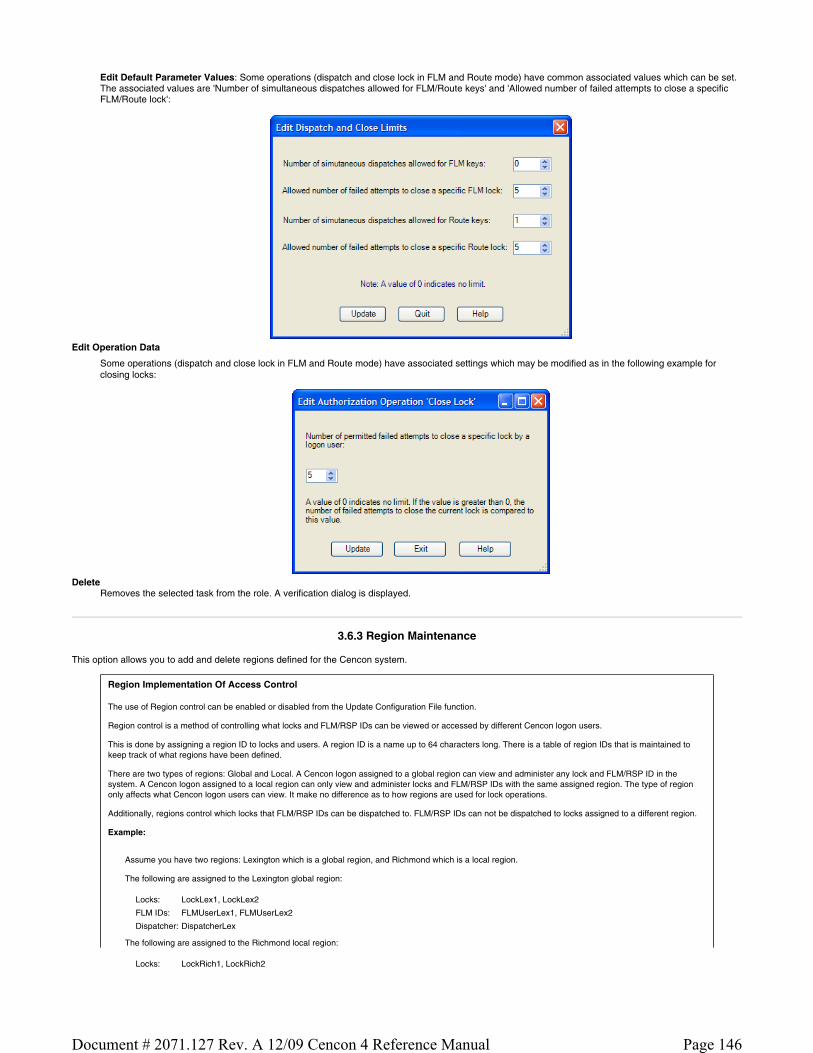
Edit Default Parameter Values: Some operations (dispatch and close lock in FLM and Route mode) have common associated values which can be set. The associated values are 'Number of simultaneous dispatches allowed for FLM/Route keys' and 'Allowed number of failed attempts to close a specific FLM/Route lock':
Edit Operation Data
Some operations (dispatch and close lock in FLM and Route mode) have associated settings which may be modified as in the following example for closing locks:
Delete
Removes the selected task from the role. A verification dialog is displayed.
3.6.3 Region Maintenance
This option allows you to add and delete regions defined for the Cencon system.
Region Implementation Of Access Control
The use of Region control can be enabled or disabled from the Update Configuration File function.
Region control is a method of controlling what locks and FLM/RSP IDs can be viewed or accessed by different Cencon logon users.
This is done by assigning a region ID to locks and users. A region ID is a name up to 64 characters long. There is a table of region IDs that is maintained to keep track of what regions have been defined.
There are two types of regions: Global and Local. A Cencon logon assigned to a global region can view and administer any lock and FLM/RSP ID in the system. A Cencon logon assigned to a local region can only view and administer locks and FLM/RSP IDs with the same assigned region. The type of region only affects what Cencon logon users can view. It make no difference as to how regions are used for lock operations.
Additionally, regions control which locks that FLM/RSP IDs can be dispatched to. FLM/RSP IDs can not be dispatched to locks assigned to a different region.
Example:
Assume you have two regions: Lexington which is a global region, and Richmond which is a local region.
The following are assigned to the Lexington global region:
The following are assigned to the Richmond local region:
Locks: LockLex1, LockLex2
FLM IDs: FLMUserLex1, FLMUserLex2
Dispatcher: DispatcherLex
Locks: LockRich1, LockRich2
Page 146Document # 2071.127 Rev. A 12/09 Cencon 4 Reference Manual

DispatcherLex can see and dispatch all of the locks - LockLex1, LockLex2, LockRich1, LockRich2. DispatcherLex can also see and dispatch all of the FLM/RSP IDs - FLMUserLex1, FLMUserLex2, FLMUserRich1, FLMUserRich2.
DispatcherRich can only see and dispatch the locks assigned to region Richmond - LockRich1, LockRich2. DispatcherRich can also only see and dispatch the users assigned to region Richmond - FLMUserRich1, FLMUserRich2.
The FLM IDs FLMUserLex1 and FLMUserLex2 can only be dispatched to the locks assigned to the same Lexington region - LockLex1, LockLex2.
The FLM IDs FLMUserRich1 and FLMUserRich2 can only be dispatched to the locks assigned to the same Richmond region - LockRich1, LockRich2.
FLM IDs: FLMUserRich1, FLMUserRich2
Dispatcher: DispatcherRich
Click on Regions under the System Category on the main window. The Region Maintenance window is displayed:
The region operations are Add, Modify and Delete:
To add a region, click on Add a Region. The Create New Region window is displayed. Enter the name of the new region, select the region type, and click on Add and Exit if you are just adding one region or Add to continue adding new regions.
Use Modify Region to change the type of an existing region. Use Delete Region to delete a region.
3.6.4 Update Configuration File
To update the configuration file, complete the following steps:
1. Click on Change Configuration Settings. The Update Configuration Data window is displayed.
Page 147Document # 2071.127 Rev. A 12/09 Cencon 4 Reference Manual
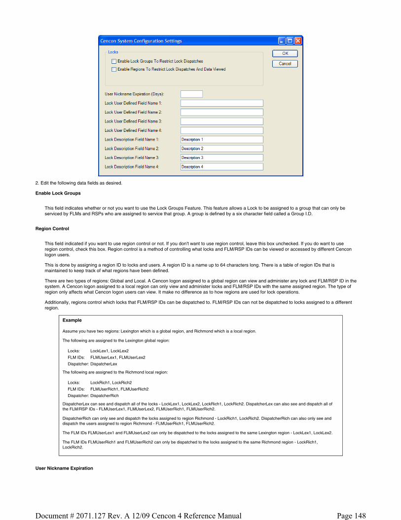
2. Edit the following data fields as desired.
Enable Lock Groups
This field indicates whether or not you want to use the Lock Groups Feature. This feature allows a Lock to be assigned to a group that can only be serviced by FLMs and RSPs who are assigned to service that group. A group is defined by a six character field called a Group I.D.
Region Control
This field indicated if you want to use region control or not. If you don't want to use region control, leave this box unchecked. If you do want to use region control, check this box. Region control is a method of controlling what locks and FLM/RSP IDs can be viewed or accessed by different Cencon logon users.
This is done by assigning a region ID to locks and users. A region ID is a name up to 64 characters long. There is a table of region IDs that is maintained to keep track of what regions have been defined.
There are two types of regions: Global and Local. A Cencon logon assigned to a global region can view and administer any lock and FLM/RSP ID in the system. A Cencon logon assigned to a local region can only view and administer locks and FLM/RSP IDs with the same assigned region. The type of region only affects what Cencon logon users can view. It make no difference as to how regions are used for lock operations.
Additionally, regions control which locks that FLM/RSP IDs can be dispatched to. FLM/RSP IDs can not be dispatched to locks assigned to a different region.
Example
Assume you have two regions: Lexington which is a global region, and Richmond which is a local region.
The following are assigned to the Lexington global region:
The following are assigned to the Richmond local region:
DispatcherLex can see and dispatch all of the locks - LockLex1, LockLex2, LockRich1, LockRich2. DispatcherLex can also see and dispatch all of the FLM/RSP IDs - FLMUserLex1, FLMUserLex2, FLMUserRich1, FLMUserRich2.
DispatcherRich can only see and dispatch the locks assigned to region Richmond - LockRich1, LockRich2. DispatcherRich can also only see and dispatch the users assigned to region Richmond - FLMUserRich1, FLMUserRich2.
The FLM IDs FLMUserLex1 and FLMUserLex2 can only be dispatched to the locks assigned to the same Lexington region - LockLex1, LockLex2.
The FLM IDs FLMUserRich1 and FLMUserRich2 can only be dispatched to the locks assigned to the same Richmond region - LockRich1, LockRich2.
User Nickname Expiration
Locks: LockLex1, LockLex2
FLM IDs: FLMUserLex1, FLMUserLex2
Dispatcher: DispatcherLex
Locks: LockRich1, LockRich2
FLM IDs: FLMUserRich1, FLMUserRich2
Dispatcher: DispatcherRich
Page 148Document # 2071.127 Rev. A 12/09 Cencon 4 Reference Manual

This field designates the number of days allowed to pass before a nickname for a user expires and must be changed to a different nickname. Nicknames can be designated for FLM and Route personnel for added security purposes. If not using nicknames in the system or you do not wish to define an expiration time for nicknames, set the value to 0.
Lock User Defined Fields 1 - 4
These fields designate the column titles to be used when they are displayed on a lock report.
Lock Description Fields 1 - 4
These fields designate the column titles to be used when they are displayed on a lock report.
3. Click on OK.
3.6.5 Change Preferences
To update the preferences, complete the following steps:
1. Click on Change Preferences. The Preferences Settings window is displayed.
2. Edit the following data fields as desired:
Help Files Directory Specify the location of the Cencon Help files.
Default Route File Directory Specify the default location for route definition files.
Mapping Software Specifies which mapping software to use for displaying geographic locations.
MapPoint is a licensed Microsoft product. It allows you to display multiple locations on a single map.
MapQuest is a free internet service (internet connection required) which displays a single location on a map.
Language Specifies the language translation used for window text and messages.
3. Click on OK to save the settings.
3.6.6 Security Hardware Report
Select Security Hardware Report to display information about the active security device. There are no operations for this report.
Sample Cencon Key Box security report:
Page 149Document # 2071.127 Rev. A 12/09 Cencon 4 Reference Manual
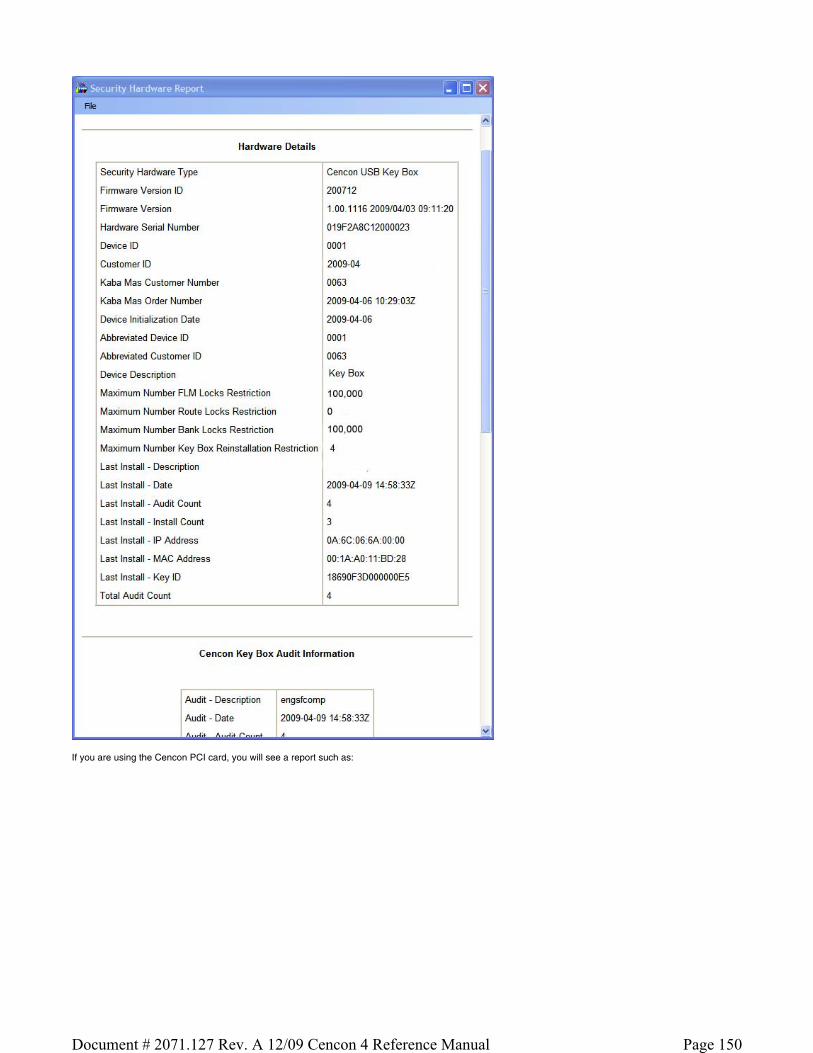
If you are using the Cencon PCI card, you will see a report such as:
Page 150Document # 2071.127 Rev. A 12/09 Cencon 4 Reference Manual

The File menu provides access to the following standard functions:
Save Save As Page Setup Print Exit
Page 151Document # 2071.127 Rev. A 12/09 Cencon 4 Reference Manual

Chapter 4 - Cencon Locks
4.1 Model Types and Operating Differences
4.1.1 Cencon Locks
The Cencon Locks operate in conjunction with the Cencon Software. From a functional standpoint, all Cencon locks offer the same basic capabilities. For more than a decade, the Cencon lock which we now refer to as Gen1, has met and exceeded the market's needs
Cencon Gen2 Locks
Those users who are familiar with the operation of the Gen1 lock will notice few differences if operating the Gen2 lock as they did the Gen1 lock. However, many product enhancements exist with the Gen2 lock that are dependent on the type of PC equipment used to activate the lock. A few highlights are as follows:
Compatibility Mode occurs when the Gen2 lock's mode is activated from Cencon software using a PCI card (FLM or Route) or from the CenBank software (Bank Mode).
Gen2 Features Available in Compatibility Mode:
Clock is in the lock, providing more accurate audit times and provide a consistent basis for all keys servicing that lock Time-stamped audits of factory mode activity. bEC indicates upon power-up that clock battery is low or dead (after up to 9 years). cEC notifies user when the clock has been reset to 1/1/2000 after battery was removed/replaced. Clearing Lock Out is easier (now any authorized key + combo can clear the LCO after the penalty period is complete). Connector for Door Contact Switch and Remote Disable function input to the lock. Pressing Keypad Prompts (#7x) displays helpful information to the field user: which modes are active; current GMT date/time; last open record and activation record by mode; key serial number & type; etc. Faster Downloading of Audit records to SA key. More audit memory storage, new audit types, and clearer audit descriptions. Back Cover can be returned to Kaba Mas for firmware upgrades in the future. Lock will not continue to display "IPI" after mode shelved or factory reset, when the key forgot to get its last close seal Improved ESD-resistance to the memory.
Full Gen2 Mode
To take advantage of its full range of features, the Gen2 lock would need to be originally activated from the Cencon 4 software using a new USB Key Box. Alternatively, if Gen2 locks were originally activated in compatibility mode and then later imported into Cencon 4 which used the USB Box, an "update activation key" could be programmed and taken to the lock in order to reinitialize it into full Gen2 Mode.
Gen2 Features Available in full Gen2 Mode (all of the Gen2 Features Available in Compatibility Mode plus the following):
Algorithm Encryption method made more secure. Lock Synchronization Key to re-sync locks with database in rare cases of audit count mismatch. Allows usage of future DS1963 keys for F, R, or B mode. Starts using a 4-digit Close Seal, improving security by encoding duress and clock/battery warning back to the dispatcher. Allows use of the Serial Interface Connection, to do remote operations or operations directly connected to Cencon PC (audit, activate, shelve, etc.). Allows a Lock Serial Number greater than 1 million to be activated and dispatched. Additional information from #7: local time by mode; which customer and USB key box activated each mode; etc. Bank Mode Features:
Expanded bank mode User Table; from 32 to 100 user IDs available. Bank mode allows User Table download to determine current active users. Time delay range will be expanded from 5-99 minutes to 1-99 minutes. Ability to set the default Bank mode combinations on the key during activation in the software.
Battery Notes
All time window processing and audit time stamps are based on the time maintained in the lock. The cEC prompt is a modified "Enter Combination" prompt which indicates that the clock has not been set. If you see this prompt, use the Cencon software to create a clock set key (see Initialize Lock Time Set Key for details).
The bEC prompt is a modified "Enter Combination" prompt which indicates that the clock battery needs replacing. When selecting a user to change the battery, choose a user who does not have time windows restrictions. If using a bank user key to open the lock and a time delay is set, the lock will honor the delay but will require additional power ups during the delay period (each power up cycle provides about 2 minutes of time).
4.1.2 Lock Operating Tips
The method for powering locks is to turn the dial to the left (counter-clockwise), using full wrist turns, until EC appears.
When performing operations that involve opening the lock, you have an approximate 40-60 second window in which to enter the combination(s) and present the key order to get OPr and open the lock. If any delay in activity occurs during that window which might cause the lock to get low on power, you should dial left to "repower" lock. Especially in dual mode, it is sometimes necessary to power the lock before entering the second combination to ensure that the lock does not power down during the operation. If the lock loses power, the operation must be restarted.
After opening and closing any lock, you should always check to ensure that the lock is physically relocked (i.e., bolt fully extended and locked in place) by turning the dial to the right. If the bolt does not retract, you can be assured the lock is secured.
4.2 Lock Operations
Page 152Document # 2071.127 Rev. A 12/09 Cencon 4 Reference Manual

The following section covers detailed Lock Operations. A few general items that apply throughout this section are noted below.
CW= Clockwise; CCW = Counter Clockwise
Note
When performing operations that involve opening the lock, you have an approximate 40-60 second window in which to enter the combination(s) and present the key(s) in order to get OPr and open the lock. If any delay in activity occurs during that window which might cause the lock to get low on power, you should dial left to "repower" the lock. Especially in dual mode, it is sometimes necessary to power the lock before entering the second combination to ensure that the lock does not power down during the operation. If the lock loses power, the operation must be restarted.
Note
If -dL appears on the lock display at anytime during an operation, it indicates that you should dial Left (CCW).
Note
After opening and closing any lock, you should always check to ensure that the lock is physically relocked (i.e., bolt fully extended and locked in place) by turning the dial to the right. If the bolt does not retract, you can be assured the lock is secured.
4.3 Lock Operations with a Door Contact Switch
If a Gen2 Cencon lock is attached to a Door Contact Switch, close seals (FLM and Route modes) and close confirmations (Bank mode) cannot be retrieved if the door is open. When the door is open, instead of an IPI prompt the lock displays OPd (Open door) and powers down, indicating that the door is open and that the close seal or close confirmation cannot be retrieved. This situation is most likely to occur If the lock bolt is extended with the door open, in which case the user is probably not going to be able to close the door and must reopen the lock to do so.
The user will require a second dispatched combination (FLM and Route modes) to open the lock, close the door, and extend the bolt to obtain the close seal (FLM and Route mode) or close confirmation (Bank mode). This second combination is obtained by the dispatcher by performing a Manager Force Close w/o Seal followed by a dispatch.
In order to dial to the EC prompt to enter the second combination to reopen the lock and allow the door to be closed, the user must dial clockwise to bypass the OPd prompt.
After EC is displayed, the user enters the second combination and presents the key in the normal manner. At this point, the lock automatically closes out the last call. An example of the lock audit for this is:
FLM, Open Sensor - door open FLM, Open/Close
It is the responsibility of the safe manufacturer to secure the Door Contact Switch and associated cables to prevent tampering.
Page 153Document # 2071.127 Rev. A 12/09 Cencon 4 Reference Manual
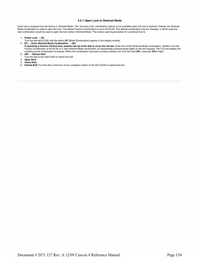
4.2.1 Open Lock In Shelved Mode
Each lock is shipped from the factory in Shelved Mode. The "one time only" combination feature is not available when the lock is shelved. Instead, the Shelved Mode combination is used to open the lock. The default Factory Combination is set to 50-25-50. The default combination may be changed, in which case the new combination would be used to open the lock while in Shelved Mode. The correct opening procedure for a shelved lock is:
1. Power Lock → EC Turn the dial left (CCW) until the letters EC (Enter Combination) appear in the display window.
2. EC → Enter Shelved Mode Combination → OPr If operating a Cencon Vertical lock, position the lip of the dial to cover the red bar. Enter the current Shelved Mode combination, whether it be the Factory Combination of 50-25-50 or a new Shelved Mode combination, by sequentially pressing those digits on the lock keypad. The LCD will display the numbers as the combination is entered. When the combination has been correctly entered, the LCD will read OPr, meaning "OPen right."
3. OPr → Retract Bolt Turn the dial to the right (CW) to retract the bolt.
4. Open Door 5. Close Door 6. Extend Bolt Turn the dial a minimum of one complete rotation to the left (CCW) to extend the bolt.
Page 154Document # 2071.127 Rev. A 12/09 Cencon 4 Reference Manual

4.2.2 Change Shelved Mode Combination
For Cencon Locks with a code level of 71, or greater, you may change the Shelved Mode combination. You may change the default Factory Combination of 50-25-50 to a new combination to be used while the lock is still in Shelved Mode. Once you have changed the combination for the first time, you may want to change the combination again to a different Shelved Mode combination. You can even change it back to the Factory combination of 50-25-50 if you would like.
Required Items: Change Key, Current Shelved Mode Combination
Note
You can only change the Shelved Mode combination while operating in Shelved Mode. Once a lock is "activated" in any mode, the Shelved Mode combination returns to the Factory Default of 50-25-50.
To change the Shelved Mode combination:
1. Power Lock → EC Turn the Dial to the left (CCW) until "EC" (Enter Combination) is displayed.
2. EC → Enter Shelved Mode Combination → OPr If operating a Cencon Vertical lock, position the lip of the dial to cover the red bar. Enter the current Shelved Mode combination (either 50-25-50 or a changed Shelved Mode combination) by sequentially pressing those digits on the lock keypad. The numbers will be displayed on the LCD as they are entered. When the combination has been correctly entered, the LCD will read OPr, meaning "OPen right."
3. OPr → Retract Bolt Turn the Dial to the right (CW) to retract the bolt.
4. Open Door 5. Insert Change Key
Insert the change key into the change key socket on the back of the lock. 6. Extend Bolt
Turn the Dial to the left (CCW) to extend the bolt. Do not close the door.
7. Power Lock →
Turn the dial to the left (CCW) until (the Change Key symbol along with Enter Combination) is displayed.
8. → Press #8 → EcF
Press the "#" button followed by the "8" button. EcF (Enter current Factory combination) will be displayed. 9. EcF → Enter Current Shelved Mode Combination → EnF
Enter the current shelved mode combination, "EnF" (Enter new Factory combination) will be displayed. 10. EnF → Enter New Combination → CnF
Select and enter the new combination. "CnF" (Confirm new Factory combination) will be displayed.
Note
The new Shelved Mode combination should be recorded and stored in a secure area.
11. CnF → Enter New Combination → POC Enter new combination again to confirm. POC (Pull Out Change key) will be displayed.
12. POC → Remove Change Key → EOP Remove the change key. EOP (End OPeration) is displayed.
13. EOP → Power Lock → EC Turn the dial to the left (CCW) until EC (Enter Combination) is displayed.
14. EC → Enter New Shelved Mode Combination → OPr If operating a Cencon Vertical lock, position the lip of the dial to cover the red bar. Enter the new shelved mode combination by pressing those digits on the lock's keypad. The numbers will be displayed on the LCD as they are entered. When the combination has been correctly entered, the LCD will read OPr, meaning "OPen right."
15. OPr → Retract Bolt Turn the Dial to the right (CW) to retract the bolt.
16. Close Door 17. Extend Bolt
Turn the Dial to the left (CCW) to extend the bolt.
Page 155Document # 2071.127 Rev. A 12/09 Cencon 4 Reference Manual

4.2.3 Display Serial Number
The Lock's Serial Number may be displayed at any time.
1. Power Lock → EC Power the Lock by turning the dial to the left (CCW) until EC appears in the display window.
2. EC → Press #2 → Sn- xx xx xx or Sn- xxx xxx xxx Press # followed by 2.
For Gen1 locks: The lock will display Sn- (Serial number) followed by the serial number, displaying two digits at a time. If the Lock Serial Number is 998877, "Sn-", then "99", then "88", then "77" will be displayed.
For Gen2 locks: The lock will display Sn- (Serial number) followed by the serial number, displaying three digits at a time. If the Lock Serial Number is 1000022, "Sn-", then "001", then "000", then "022" will be displayed.
3. Sn- xx xx xx or Sn- xxx xxx xxx → Record Serial Number Record the Serial Number. You will need this number when you activate the lock.
Note
As long as the Gen2 serial number starts with 000 (3 zeros) you can enter this Gen2 serial number into versions of Cencon and CenBank software released before 2009, by ignoring the first 3 digits and typing in only the last 6 digits. If your Gen2 lock serial number begins the first 3 digits with 001 or higher, you must be using Cencon version 4.0 or higher to activate the lock.
Note
This display can be canceled by pressing the asterisk (*) key, or it will automatically be canceled when the lock powers down.
Page 156Document # 2071.127 Rev. A 12/09 Cencon 4 Reference Manual

4.2.4 FLM and Route Lock Activation
Lock activation requires a coordinated effort between a Dispatcher and an FLM or Route Person. Remember that a lock may be activated in more than one mode at a time, which means that sometimes the lock will already be activated in one mode when you want to activate it in another.
A Dispatcher activates the lock at the PC using the software program and the red SA key. An FLM or Route Person physically goes to the lock to complete the activation, using the initialized SA key, a blue F or yellow R key, change key and an activation combination obtained from the Dispatcher.
Note
If the lock is already active in another mode, a service call must be issued for that mode so that the lock can be opened for the new activation.
A Change Key is required for this procedure. This is a tool that will normally be in the possession of the FLM or Route Service Person. The change key has two prongs that, when extended, fit securely into the change key holes on the back of the lock body. Any change key may be used in any Cencon Lock. The change key is not encoded or unique in any way.
To Activate Lock from Shelved Mode:
This process should be followed when the lock is not currently activated in any mode; that is, it is in Shelved Mode.
Required Items: Shelved Mode Combination, Change Key, SA Key, F or R Key
1. Power Lock → EC Turn the dial to the left (CCW) until EC (Enter Combination) appears in the display window.
2. EC → Enter Shelved Mode Combination → OPr If operating a Cencon Vertical lock, position the lip of the dial to cover the red bar. When EC is displayed, key in the current Shelved Mode combination. This could either be the default Factory Combination of 50-25-50 or a unique combination that was set while the lock was in Shelved Mode. OPr (OPen right) is displayed.
3. OPr → Retract Bolt At OPr turn the dial to the right (CW) to retract the bolt.
4. Open Door 5. Insert Change Key
Extend the prongs on the change key and insert it into the change key socket on the back of the Lock. 6. Extend Bolt
With the door open, turn the dial to the left (CCW) to extend the bolt.
7. Power Lock →
Turn the dial to the left (CCW) until (the Change Key symbol along with Enter Combination) appears in the display window.
8. → Enter Shelved Mode Combination → ISA
If operating a Cencon Vertical lock, position the lip of the dial to cover the red bar. When is displayed, key in the current Shelved Mode
combination. Again, this could either be the default Factory Combination of 50-25-50 or a unique combination that was set while the lock was in Shelved Mode. ISA (Insert Supervisor Audit key) is displayed.
9. ISA → Insert and Hold SA Key → Ini Insert and hold the SA Key in the key reader on the side of the lock. The lock will display Ini (Initializing) with a flashing bar over the "n" while the information is being processed.
10. Ini → POC Continue to hold the SA Key in the reader until POC (Pull Out Change Key) is displayed.
11. POC → Remove SA Key & Pull Out Change Key → OPr At the POC prompt remove the SA Key and Pull Out the Change key. OPr (OPen right) is displayed.
12. OPr → Retract Bolt At OPr turn the dial to the right (CW) to retract the bolt.
13. Extend Bolt Turn the Dial to the left (CCW) to extend the bolt.
14. Power Lock → EC Turn the dial to the left (CCW) until EC (Enter Combination) appears in the display window.
15. EC → Enter Activation Combination → IPI If operating a Cencon Vertical lock, position the lip of the dial to cover the red bar. When EC is displayed, key in the activation combination. This is the combination that was issued at the PC software. IPI (Insert Personal Identifier) is displayed.
16. IPI → Insert Personal Identifier Key → OPr At IPI insert a valid FLM or Route key. OPr is displayed.
Note
If you have activated the lock in Dual Access Mode, the lock will prompt EC2 for the second combination and then IP2 for the second user's key before OPr will appear.
17. OPr → Retract Bolt At OPr turn the dial to the right (CW) to retract the bolt.
18. Close Door 19. Extend Bolt
Turn the dial to the left (CCW) to extend the bolt. 20. Power Lock → IPI
Turn the dial to the left (CCW) until IPI (Insert Personal Identifier) appears. 21. IPI → Insert Personal Identifier Key → cxx or Cxx xx (Close Seal)
At IPI insert a valid FLM or Route key.
Page 157Document # 2071.127 Rev. A 12/09 Cencon 4 Reference Manual

For Gen1 locks: The lock will display cxx (close seal) where xx is a two-digit number that is the Close Seal number for this opening. For Gen2 locks: The lock will display Cxx xx (Close seal) where xx xx is a four-digit number that is the Close Seal number for this opening.
Note
To remove a two-digit close seal from the display, turn the dial to the left (CCW) until EOP appears. To stop the display of a four-digit close seal, press and briefly hold the * key. If you do not choose to manually eliminate the display of the close seal, it will automatically disappear when the lock powers down.
Note
An audit record will be recorded each time a key is inserted in the opening and closing operations.
22. cxx or Cxx xx → Record Close Seal This Close Seal number should be called in to the Dispatch Center to close the activation call.
To Activate an FLM or Route Lock Mode from an Active FLM or Route Mode:
This procedure should be used when the lock has already been activated in at least one mode, either FLM or Route, and you wish to activate the other Cencon operating mode.
Note
Since the Lock has already been activated in one Mode and you are activating another, you will be required to meet someone at the Lock who has the authority to open it.
Required Items: Default Factory Combination, Change Key, SA Key, Activation Combination, F or R Key, Service Call Combination and F or R Key for Active Mode.
1. Power Lock → EC Turn the dial to the left (CCW) until EC (Enter Combination) appears in the display window.
2. EC → Enter Service Call Combination for Active Mode → IPI If operating a Cencon Vertical lock, position the lip of the dial to cover the red bar. When EC is displayed, key in the one time combination that is already active. When the final number of the combination is keyed, the display will prompt IPI (Insert Personal Identifier).
3. IPI → Insert Personal Identifier Key → OPr At IPI insert the Personal Identifier Key for the mode that is already active into the Lock's key reader. OPr (OPen right) is displayed.
4. OPr → Retract Bolt At OPr turn the dial to the right (CW) to retract the bolt.
5. Open Door 6. Insert Change Key
Extend the prongs on the change key and insert it into the change key socket on the back of the Lock. 7. Extend Bolt
With the door open, turn the dial left (CCW) to extend the bolt.
8. Power Lock →
Turn the Dial left (CCW) until (the change key symbol along with Enter Combination) appears in the display window.
9. → Enter Factory Combination → ISA
If operating a Cencon Vertical lock, position the lip of the dial to cover the red bar. Enter the Default Factory Combination of 50-25-50. ISA (Insert Supervisor Audit key) is displayed.
10. ISA → Insert and Hold SA Key → Ini Insert and hold the SA Key in the key reader on the side of the lock. The lock will display Ini (Initializing) with a flashing bar over the "n" while the information is being processed.
11. Ini → POC Continue to hold the SA Key in the reader until POC (Pull Out Change Key) is displayed.
12. POC → Remove SA Key & Pull Out Change Key → OPr At the POC prompt remove the SA Key and Pull Out the Change key. OPr (OPen right) is displayed.
13. OPr → Retract Bolt At OPr turn the dial to the right (CW) to retract the bolt.
14. Extend Bolt With the door open, turn the dial left (CCW) to extend the bolt.
15. Power Lock → IPI Turn the Dial CCW until IPI (Insert Personal Identifier) appears in the display window.
16. IPI → Insert Personal Identifier Key → cxx or Cxx xx (Close Seal) At IPI insert a valid FLM or Route key. For Gen1 locks: The lock will display cxx (close seal) where xx is a two-digit number that is the Close Seal number for this opening. For Gen2 locks: The lock will display Cxx xx (Close seal) where xx xx is a four-digit number that is the Close Seal number for this opening.
Note
To remove a two-digit close seal from the display, turn the dial to the left (CCW) until EOP appears. To stop the display of a four-digit close seal, press and briefly hold the * key. If you do not choose to manually eliminate the display of the close seal, it will automatically disappear when the lock powers down.
Note
Page 158Document # 2071.127 Rev. A 12/09 Cencon 4 Reference Manual

An audit record will be recorded each time a key is inserted for opening and closing operations.
17. cxx or Cxx xx → Record Service Call Close Seal This is the Close Seal number for the original service call that opened the Lock. It should be called in to Dispatch to close out this service call.
18. Power Lock → EC Turn the dial to the left (CCW) until EC (Enter Combination) appears.
19. EC → Enter Activation Combination → IPI If operating a Cencon Vertical lock, position the lip of the dial to cover the red bar. When EC is displayed, key in the activation combination for the new mode being activated. IPI is displayed.
20. IPI → Insert Personal Identifier Key → OPr At IPI insert the Personal Identifier Key for the new mode being activated. OPr (OPen right) is displayed.
21. OPr → Retract Bolt At OPr turn the dial right (CW) to retract the bolt.
22. Close Door 23. Extend Bolt
Extend the bolt and secure the Lock by turning the dial left (CCW). 24. Power Lock → IPI
Turn the dial left (CCW) until IPI (Insert Personal Identifier) appears. 25. IPI → Insert Personal Identifier Key → cxx or Cxx xx (Close Seal)
At IPI insert a valid FLM or Route key. For Gen1 locks: The lock will display cxx (close seal) where xx is a two-digit number that is the Close Seal number for this opening. For Gen2 locks: The lock will display Cxx xx (Close seal) where xx xx is a four-digit number that is the Close Seal number for this opening.
Note
To remove a two-digit close seal from the display, turn the dial to the left (CCW) until EOP appears. To stop the display of a four-digit close seal, press and briefly hold the * key. If you do not choose to manually eliminate the display of the close seal, it will automatically disappear when the lock powers down.
Note
An audit record will be recorded each time a key is inserted for opening and closing operations.
26. cxx or Cxx xx → Record Activation Close Seal This Close Seal number should be called in to the Dispatch Center to close the activation call.
To Activate an FLM or Route Lock Mode from an Active Bank Mode:
This procedure should be used when the lock has already been activated in Bank mode and you wish to activate another Cencon operating mode.
Note
Since the Lock has already been activated in one Mode and you are activating another, you will be required to meet someone at the Lock who has the authority to open it.
Required Items: Default Factory Combination, Change Key, SA Key, Activation Combination, F or R Key, Bank User Combination and B Key for Active Mode.
1. Power Lock → EC Turn the dial to the left (CCW) until EC (Enter Combination) appears in the display window.
2. EC → Enter Bank User Combination for Active Mode → IPI If operating a Cencon Vertical lock, position the lip of the dial to cover the red bar. When EC is displayed, key in the one time combination that is already active. When the final number of the combination is keyed, the display will prompt IPI (Insert Personal Identifier).
3. IPI → Insert Personal Identifier Key → OPr At IPI insert the Personal Identifier Key for Bank mode into the Lock's key reader. OPr (OPen right) is displayed.
4. OPr → Retract Bolt At OPr turn the dial to the right (CW) to retract the bolt.
5. Open Door 6. Insert Change Key
Extend the prongs on the change key and insert it into the change key socket on the back of the Lock. 7. Extend Bolt
With the door open, turn the dial left (CCW) to extend the bolt.
8. Power Lock →
Turn the Dial left (CCW) until (the change key symbol along with Enter Combination) appears in the display window.
9. → Enter Factory Combination → ISA
If operating a Cencon Vertical lock, position the lip of the dial to cover the red bar. Enter the Default Factory Combination of 50-25-50. ISA (Insert Supervisor Audit key) is displayed.
10. ISA → Insert and Hold SA Key → Ini Insert and hold the SA Key in the key reader on the side of the lock. The lock will display Ini (Initializing) with a flashing bar over the "n" while the information is being processed.
11. Ini → POC Continue to hold the SA Key in the reader until POC (Pull Out Change Key) is displayed.
12. POC → Remove SA Key & Pull Out Change Key → OPr At the POC prompt remove the SA Key and Pull Out the Change key. OPr (OPen right) is displayed.
Page 159Document # 2071.127 Rev. A 12/09 Cencon 4 Reference Manual

13. OPr → Retract Bolt At OPr turn the dial to the right (CW) to retract the bolt.
14. Extend Bolt With the door open, turn the dial left (CCW) to extend the bolt.
15. Power Lock → IPI Turn the Dial CCW until IPI (Insert Personal Identifier) appears in the display window.
16. IPI → Insert Personal Identifier Key → EOP (End of OPeration) At IPI insert a valid Bank key to confirm the lock is closed and to display EOP (End of OPeration)
Note
An audit record will be recorded each time a key is inserted for opening and closing operations.
17. Power Lock → EC Turn the dial to the left (CCW) until EC (Enter Combination) appears.
18. EC → Enter Activation Combination → IPI If operating a Cencon Vertical lock, position the lip of the dial to cover the red bar. When EC is displayed, key in the activation combination for the new mode being activated. IPI is displayed.
19. IPI → Insert Personal Identifier Key → OPr At IPI insert the Personal Identifier Key for the new mode being activated. OPr (OPen right) is displayed.
20. OPr → Retract Bolt At OPr turn the dial right (CW) to retract the bolt.
21. Close Door 22. Extend Bolt
Extend the bolt and secure the Lock by turning the dial left (CCW). 23. Power Lock → IPI
Turn the dial left (CCW) until IPI (Insert Personal Identifier) appears. 24. IPI → Insert Personal Identifier Key → cxx or Cxx xx (Close Seal)
At IPI insert a valid FLM or Route key. For Gen1 locks: The lock will display cxx (close seal) where xx is a two-digit number that is the Close Seal number for this opening. For Gen2 locks: The lock will display Cxx xx (Close seal) where xx xx is a four-digit number that is the Close Seal number for this opening.
Note
To remove a two-digit close seal from the display, turn the dial to the left (CCW) until EOP appears. To stop the display of a four-digit close seal, press and briefly hold the * key. If you do not choose to manually eliminate the display of the close seal, it will automatically disappear when the lock powers down.
Note
An audit record will be recorded each time a key is inserted for opening and closing operations.
25. cxx or Cxx xx → Record Activation Close Seal This Close Seal number should be called in to the Dispatch Center to close the activation call.
Page 160Document # 2071.127 Rev. A 12/09 Cencon 4 Reference Manual

4.2.5 Open Lock - FLM or Route Mode
Once a lock has been activated in FLM and/or Route Mode, a "one time combination" is needed to open the lock. This combination is issued from the Cencon software. The correct opening procedure for an activated lock is:
Required Items: Issued Combination, Blue F or Yellow R Key
1. Power Lock → EC Turn the dial to the left (CCW) until EC (Enter Combination) appears in the display window.
2. EC → Enter Combination → IPI If operating a Cencon Vertical lock, position the lip of the dial to cover the red bar. When EC is displayed, key in the one time combination. When the final number of the combination is keyed, the display will prompt IPI (Insert Personal Identifier).
3. IPI → Insert Personal Identifier Key → OPr At IPI insert a valid FLM or Route key in the lock's key reader. OPr (OPen right) is displayed.
4. Opr → Retract Bolt At OPr turn the dial to the right (CW) to retract the bolt.
5. Open Door 6. Perform Operations
Perform the service or route operations for the lock. 7. Close Door 8. Extend Bolt → IPI
Extend the bolt and secure the lock by turning the dial left (CCW). When the lock is fully locked, the display will prompt IPI (Insert Personal Identifier). 9. IPI → Insert Personal Identifier Key → cxx or Cxx xx (Close Seal)
At IPI insert a valid FLM or Route key. For Gen1 locks: The lock will display cxx (close seal) where xx is a two-digit number that is the Close Seal number for this opening. For Gen2 locks: The lock will display Cxx xx (Close seal) where xx xx is a four-digit number that is the Close Seal number for this opening.
Note
To remove a two-digit close seal from the display, turn the dial to the left (CCW) until EOP appears. To stop the display of a four-digit close seal, press and briefly hold the * key. If you do not choose to manually eliminate the display of the close seal, it will automatically disappear when the lock powers down.
Note
An audit record will be recorded each time a key is inserted for opening and closing operations.
10. cxx or Cxx xx → Record Close Seal This Close Seal number should be called in to Dispatch to close out this service call if the call was dispatched as an individual call (FLM or Route). If dispatched as a part of a Route, the Close Seal can be called in at the close of the call. It can also be read from the key or entered manually into a menu at the PC upon completion of the route.
Page 161Document # 2071.127 Rev. A 12/09 Cencon 4 Reference Manual

4.2.6 Open Lock - FLM or Route Dual Mode
If a lock has been activated in FLM and/or Route Dual Mode, two unique combinations are required to open the lock. Each combination is a one time combination that is issued from the Cencon software. The procedure for opening the lock in Dual Mode is:
Required Items: Two Issued Combinations, Two Blue F or Yellow R Keys
1. Power Lock → EC Turn the dial to the left (CCW) until EC (Enter Combination) appears in the display window.
2. EC → Enter 1st Combination → IPI If operating a Cencon Vertical lock, position the lip of the dial to cover the red bar. When EC is displayed, key in the one time combination. When the final number of the combination is keyed, the display will prompt IPI (Insert Personal Identifier).
3. IPI → Insert 1st Personal Identifier Key → EC2 At IPI insert the first valid FLM or Route key in the Lock's key reader. For Dual Mode EC2 (Enter Combination 2) will be displayed.
4. EC2 → Enter 2nd Combination → IP2 At EC2 key in the second valid combination. IP2 (Insert Personal Identifier 2) will be displayed.
5. IP2 → Insert 2nd Personal Identifier Key → OPr At IP2 insert the second valid FLM or Route key. OPr (OPen right) will be displayed.
6. OPr → Retract Bolt At OPr turn the dial to the right (CW) to retract the bolt.
7. Open Door 8. Perform Operations
Perform the service or route operations for the lock. 9. Close Door
10. Extend Bolt → IPI Extend the bolt and secure the lock by turning the dial left (CCW). When the lock is fully locked, the display will prompt IPI (Insert Personal Identifier).
11. IPI → Insert Personal Identifier Key → cxx or Cxx xx (Close Seal) At IPI insert a valid FLM or Route key. For Gen1 locks: The lock will display cxx (close seal) where xx is a two-digit number that is the Close Seal number for this opening. For Gen2 locks: The lock will display Cxx xx (Close seal) where xx xx is a four-digit number that is the Close Seal number for this opening.
Note
To remove a two-digit close seal from the display, turn the dial to the left (CCW) until EOP appears. To stop the display of a four-digit close seal, press and briefly hold the * key. If you do not choose to manually eliminate the display of the close seal, it will automatically disappear when the lock powers down.
Note
An audit record will be recorded each time a key is inserted for opening or closing operations. In the case where a lock is operating in Dual Mode, two records will be written for the closing even though only one key is required to retrieve the close seal and end the call.
12. cxx or Cxx xx → Record Close Seal This Close Seal number should be called in to Dispatch to close out this service call if the call was dispatched as an individual call (FLM or Route). If dispatched as a part of a Route, the Close Seal can be called in at the close of the call, or it can be read from the key or entered into a menu upon completion of the route.
Page 162Document # 2071.127 Rev. A 12/09 Cencon 4 Reference Manual
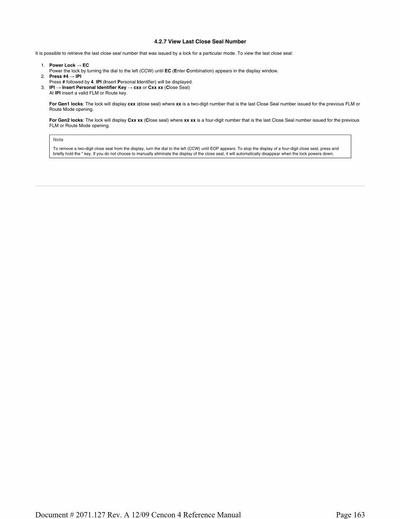
4.2.7 View Last Close Seal Number
It is possible to retrieve the last close seal number that was issued by a lock for a particular mode. To view the last close seal:
1. Power Lock → EC Power the lock by turning the dial to the left (CCW) until EC (Enter Combination) appears in the display window.
2. Press #4 → IPI Press # followed by 4. IPI (Insert Personal Identifier) will be displayed.
3. IPI → Insert Personal Identifier Key → cxx or Cxx xx (Close Seal) At IPI insert a valid FLM or Route key. For Gen1 locks: The lock will display cxx (close seal) where xx is a two-digit number that is the last Close Seal number issued for the previous FLM or Route Mode opening. For Gen2 locks: The lock will display Cxx xx (Close seal) where xx xx is a four-digit number that is the last Close Seal number issued for the previous FLM or Route Mode opening.
Note
To remove a two-digit close seal from the display, turn the dial to the left (CCW) until EOP appears. To stop the display of a four-digit close seal, press and briefly hold the * key. If you do not choose to manually eliminate the display of the close seal, it will automatically disappear when the lock powers down.
Page 163Document # 2071.127 Rev. A 12/09 Cencon 4 Reference Manual

4.2.8 Display Audit Counts
There are two types of counts that are tracked in the locks. The first type tracks the number of openings in each activated mode for the time period of an activation. The second type of count tracks the total number of openings for the lifetime of the lock.
The lock always keeps track of how many times it has been opened (Total Audit Count) no matter in which mode the opening occurred, including Shelved Mode, FLM, Route, and Bank. To learn the Total Audit Count, press the pound symbol, “#,” followed by the “3” whenever “EC” is displayed on the LCD. The display will flash two sets of numbers alternately on the screen. When taken as one four-digit number, this represents the Total Audit Count. For instance, if the LCD flashes “AC-” then “00” followed by “07,” the lock has a Total Audit Count of “0007,” meaning the lock has been opened seven times in all modes combined. This display can be cancelled by pressing the asterisk (*) button. The Total Audit Count does not reset when the lock is shelved. Once the counter exceeds 9999 openings, the Gen2 lock begins displaying more digits.
To Obtain the Audit Count for a Mode:
To retrieve the audit count for a Mode activation period, a valid PI key is required. The type of Personal Identifier key inserted in the key reader will tell the lock which Audit Count to show.
Note
In current versions of the lock the audit counts are initialized when a lock is activated. This allows you to retrieve the audit count for the last activated time period for a specific mode. In older versions the counts are reset when the lock is shelved; therefore, previous activation period counts are not available.
Required Items: Blue F or Yellow R Key
1. Power Lock → EC Turn the dial to the left (CCW) until EC (Enter Combination) appears in the display window.
2. Press ## → IPI Press the pound (#) button twice. The display will prompt IPI (Insert Personal Identifier).
3. IPI → Insert Personal Identifier Key → SC- xx xx or SS- xx xx At IPI insert a valid FLM or Route key in the Lock's key reader. SC will display if the lock is active . SS will display if the lock is shelved. The display will then indicate the Audit Count for the Mode of the key that was inserted, displayed two digits at a time.
Note
This display can be canceled by pressing the asterisk (*) button, or it will automatically be canceled when the lock powers down.
To Obtain the Total Audit Count for All Modes (Including Shelved Mode):
1. Power Lock → EC Turn the dial to the left (CCW) until EC (Enter Combination) appears in the display window.
2. Press #3 → AC- xx xx AC- will display followed by the total audit count for all modes, displayed two digits at a time.
Note
This display can be canceled by pressing the asterisk (*) button, or it will automatically be canceled when the lock powers down.
Page 164Document # 2071.127 Rev. A 12/09 Cencon 4 Reference Manual

4.2.9 Retrieve Audit Download From Lock
It is possible to use an initialized Supervisor Audit key to retrieve valuable records from the Cencon lock. The information is downloaded from the lock into the SA key, which is then returned to the Cencon dispatch center. The information in the key can then be extracted by a Supervisor by downloading it into the PC system via the Reports Menu. To retrieve the audit from the lock:
Required Items: Initialized Red SA Key
Note - Gen2 Locks
A 5 minute delay will be imposed if more than five (5) #0 operations are done in 5 minutes (a 'dLY' prompt is displayed). Either wait for the delay to elapse or open the lock to clear the count and reset the delay.
1. Power Lock → EC Turn the dial to the left (CCW) until EC (Enter Combination) appears in the display window.
2. EC → Press #0 → -dL or ISA Press the pound (#) button followed by the 0 button.
3. -dL → ISA (Gen2 locks only) For Gen2 locks, the -dL (dial Left) prompt will be displayed indicating that the user is required to dial counter-clockwise (CCW) to supply additional power to the lock before the ISA (Insert SA key) prompt is displayed.
4. ISA → Insert and Hold SA Key → Aud ISA will be displayed. Insert and hold the initialized Supervisor Audit key in the lock's key reader. The lock will display Aud (Audit in Progress) with a flashing bar over the "u" while the Audit Download is being processed.
5. Aud → EOP Continue to hold the SA Key in the reader until EOP (End of OPeration) is displayed.
Note
You must periodically turn the dial to maintain power during this time.
6. EOP → Remove SA Key When the display prompts EOP, remove the SA key.
7. Return SA Key Return the SA Key to the dispatch center to be read by the Supervisor.
Page 165Document # 2071.127 Rev. A 12/09 Cencon 4 Reference Manual

4.2.10 Shelve Lock (at Lock)
When a lock mode is deactivated, we say that the mode has been "shelved". When all modes are deactivated, the lock is shelved or in Shelved Mode. Lock shelving requires a coordinated effort between a Special Supervisor and an FLM or Route Person. An SA key must be specially prepared and taken to the lock. Once the shelving procedure has taken place at the lock, the SA key is returned to the Dispatch Center where information is extracted from the key. Remember that you must shelve each mode of the lock if you wish to return the lock to Shelved Mode.
We will need a change key for these procedures, which is a tool that will normally be in the possession of the FLM or Route Service Person. The change key has two prongs that, when extended, fit securely into the change key holes on the rear of the lock body. Any change key may be used in any Cencon lock. The change key is not encoded or unique in any way.
Note
Keep in mind that the lock may or may not be activated in Bank Mode. Bank Mode can only be shelved through the Cenbank System or through Cencon 4.0 or later version of the Cencon software.
To Shelve A Lock Mode or Modes using FLM or Route Mode:
This procedure should be used when you want to shelve any combination of FLM, Route Mode, or Bank Mode (Cencon 4.0 or later only).
Note
The designation of how many modes are to be shelved, and which ones, occurs at the PC using the Cencon software. That information is written to an SA key which is then used in this process.
If you will be shelving ALL active modes, this process will return the lock to Shelved Mode where it will open with the Factory Combination of 50-25-50.
Required Items: Blue F or Yellow R Key, Shelving Combination, Change Key, Red SA Key
1. Power Lock → EC Turn the dial to the left (CCW) until EC (Enter Combination) appears in the display window.
2. EC → Enter Shelving Combination → IPI If operating a Cencon Vertical lock, position the lip of the dial to cover the red bar. When EC is displayed, key in the one time shelving combination. When the final number of the combination is keyed, the display will prompt IPI (Insert Personal Identifier).
3. IPI → Insert Key → OPr At IPI insert the key for the mode being shelved into the Lock's key reader. OPr is displayed.
Note
If the lock is activated for Dual Combination Access, the lock will prompt EC2 for the second combination and then IP2 for the second user's key before OPr will appear.
4. OPr → Retract Bolt At OPr turn the dial right (CW) to retract the bolt.
5. Open Door 6. Insert Change Key
Extend the prongs on the change key and insert it into the change key socket on the back of the lock. Do not close the door. 7. Extend Bolt
With the door open, turn the dial left (CCW) to extend the bolt.
8. Power Lock →
Turn the dial to the left (CCW) until (the Change Key symbol along with EC) appears in the display window.
9. → Enter Factory Combination → ISA
If operating a Cencon Vertical lock, position the lip of the dial to cover the red bar. Enter the default Factory Combination of 50-25-50. ISA is displayed.
10. ISA → Insert SA Key → POC After the Factory Combination has been correctly entered, the ISA symbol, meaning "Insert Supervisor Audit" key will be displayed. Insert the Supervisor Audit Key in the Lock's key reader and continue to hold it there until POC is displayed.
11. POC → Remove SA Key AND Pull Out Change Key → OPr At the POC prompt remove the SA Key and Pull Out the Change key. OPr is displayed.
12. OPr → Retract Bolt At OPr turn the dial to the right (CW) to retract the bolt.
13. Close Door 14. Extend Bolt
Turn the dial to the left (CCW) to extend the bolt. 15. Power Lock → IPI
Turn the dial to the left (CCW) until IPI (Insert Personal Identifier) appears in the display window. 16. IPI → Insert Personal Identifier Key → cxx or Cxx xx (Close Seal)
At IPI insert a valid FLM or Route key. For Gen1 locks: The lock will display cxx (close seal) where xx is a two-digit number that is the Close Seal number for this opening. For Gen2 locks: The lock will display Cxx xx (Close seal) where xx xx is a four-digit number that is the Close Seal number for this opening.
Note
An audit record will be recorded each time a key is inserted for opening and closing operations.
Page 166Document # 2071.127 Rev. A 12/09 Cencon 4 Reference Manual

17. cxx or Cxx xx → Record Shelving Close Seal This Close Seal number should be called in to Dispatch to close the shelving.
Note
If the lock has been shelved in ALL active modes, you should at this time test the opening of the lock with the Default Factory Combination of 50-25-50.
18. Return SA Key Return the SA Key to the Dispatch Center to verify the shelving operation.
To Shelve A Lock Mode or Modes using Bank Mode:
This procedure should be used when you want to shelve any combination of FLM, Route Mode, or Bank Mode (Cencon 4.0 or later only).
Note
The designation of how many modes are to be shelved, and which ones, occurs at the PC using the Cencon software. That information is written to an SA key which is then used in this process.
If you will be shelving ALL active modes, this process will return the lock to Shelved Mode where it will open with the Factory Combination of 50-25-50.
Required Items: Teal B Key, User Key Combination, Change Key, Red SA Key
1. Power Lock → EC Turn the dial to the left (CCW) until EC (Enter Combination) appears in the display window.
2. EC → Enter User Key Combination → IPI If operating a Cencon Vertical lock, position the lip of the dial to cover the red bar. When EC is displayed, key in the one time shelving combination. When the final number of the combination is keyed, the display will prompt IPI (Insert Personal Identifier).
3. IPI → Insert Key → OPr At IPI insert the key for the mode being shelved into the Lock's key reader. OPr is displayed.
Note
If the lock is activated for Dual Combination Access, the lock will prompt EC2 for the second combination and then IP2 for the second user's key before OPr will appear.
4. OPr → Retract Bolt At OPr turn the dial right (CW) to retract the bolt.
5. Open Door 6. Insert Change Key
Extend the prongs on the change key and insert it into the change key socket on the back of the lock. Do not close the door. 7. Extend Bolt
With the door open, turn the dial left (CCW) to extend the bolt.
8. Power Lock →
Turn the dial to the left (CCW) until (the Change Key symbol along with EC) appears in the display window.
9. → Enter Factory Combination → ISA
If operating a Cencon Vertical lock, position the lip of the dial to cover the red bar. Enter the default Factory Combination of 50-25-50. ISA is displayed.
10. ISA → Insert SA Key → POC After the Factory Combination has been correctly entered, the ISA symbol, meaning "Insert Supervisor Audit" key will be displayed. Insert the Supervisor Audit Key in the Lock's key reader and continue to hold it there until POC is displayed.
11. POC → Remove SA Key AND Pull Out Change Key → OPr At the POC prompt remove the SA Key and Pull Out the Change key. OPr is displayed.
12. OPr → Retract Bolt At OPr turn the dial to the right (CW) to retract the bolt.
13. Close Door 14. Extend Bolt
Turn the dial to the left (CCW) to extend the bolt. 15. Power Lock → IPI
Turn the dial to the left (CCW) until IPI (Insert Personal Identifier) appears in the display window. 16. IPI → Insert Personal Identifier Key → EOP (End of OPeration)
At IPI insert a valid Bank key to confirm the lock is closed and to display EOP (End of OPeration)
Note
An audit record will be recorded each time a key is inserted for opening and closing operations.
Note
If the lock has been shelved in ALL active modes, you should at this time test the opening of the lock with the Default Factory Combination of 50-25-50.
17. Return SA Key Return the SA Key to the Dispatch Center to verify the shelving operation.
Page 167Document # 2071.127 Rev. A 12/09 Cencon 4 Reference Manual

Page 168Document # 2071.127 Rev. A 12/09 Cencon 4 Reference Manual

4.2.11 Bank Lock Activation
Take the initialized SA key, a Change Key, and a minimum of one lock user’s Bank key to the lock. The lock will be in Shelved mode so it can be opened with the Shelved Mode combination (either 50-25-50 or a changed combination) and no PI. After Activating the lock, you need to change the combination for at least one of the Users. All Bank User keys are initially set to the 50-25-50 combination, but will not open the Lock until changed to a valid new combination. Follow this procedure to activate the Lock and change a user combination:
To Activate a Bank Lock from Shelved Mode:
Required Items: Shelved Mode Combination, Change Key, SA Key, B Key
1. Power Lock → EC Turn the dial to the left (CCW) until EC (Enter Combination) appears in the display window.
2. EC → Enter Shelved Mode Combination → OPr If operating a Cencon Vertical lock, position the lip of the dial to cover the red bar. When EC is displayed, key in the current Shelved Mode combination. This could either be the default Factory Combination of 50-25-50 or a unique combination that was set while the lock was in Shelved Mode. OPr (OPen right) is displayed.
3. OPr → Retract Bolt At OPr turn the dial to the right (CW) to retract the bolt.
4. Open Door 5. Insert Change Key
Extend the prongs on the change key and insert it into the change key socket on the back of the Lock while OPr is displayed. 6. Extend Bolt
With the door open, turn the dial to the left (CCW) to extend the bolt.
7. Power Lock →
Turn the dial to the left (CCW) until (the Change Key symbol along with Enter Combination) appears in the display window.
8. → Enter Shelved Mode Combination → ISA
If operating a Cencon Vertical lock, position the lip of the dial to cover the red bar. When EC is displayed, key in the current Shelved Mode combination. Again, this could either be the default Factory Combination of 50-25-50 or a unique combination that was set while the lock was in Shelved Mode. ISA (Insert Supervisor Audit key) is displayed.
9. ISA → Insert and Hold SA Key → InI Insert and hold the SA Key in the key reader on the side of the lock. The lock will display InI (InItializing) with a flashing bar over the "n" while the information is being processed.
10. InI → POC Continue to hold the SA Key in the reader until POC (Pull Out Change Key) is displayed.
11. POC → Remove SA Key & Pull Out Change Key → OPr At the POC prompt remove the SA Key and Pull Out the Change key. OPr (OPen right) is displayed.
12. OPr → Retract Bolt At OPr turn the dial to the right (CW) to retract the bolt.
13. Extend Bolt Turn the Dial to the left (CCW) to extend the bolt.
14. Power Lock → EC Turn the dial to the left (CCW) until EC (Enter Combination) appears in the display window.
15. EC → Enter Default User Combination → IPI Enter the default user combination of 50-25-50 for User 00. The lock will prompt IPI (Insert Personal Identifier key) on the display.
Note
To determine the code level of your lock, see Appendix F.
For Locks with Code Level 64B and below:
16. IPI → Insert 00 Personal Identifier Key → bc xxxxxx Insert User 00’s Personal Identifier B Key into the key reader. The lock will display bc (bank combination) followed by the new combination, displayed two digits at a time.
17. bc xxxxxx → Record Combination and Press * → cc Record the combination and press * to acknowledge receipt of new combination. The display will prompt cc (confirm combination).
18. cc → Enter New Combination → EOP Enter the new combination by pressing those digits on the lock's keypad. The numbers will be displayed as they are entered. EOP (End OPeration) will be displayed. The newly confirmed combination is now active for that Bank User and Personal Identifier Key. (Go to Step 19.)
Note
If a flashing lightning bolt appears on the display, the combination was not confirmed properly. Reset by pressing the * key and rekey the operation.
For Locks with Code Level 65B and above:
16. IPI → Insert 00 Personal Identifier Key → EnC Insert User 00’s Personal Identifier B Key into the key reader. The lock will display EnC (Enter Combination).
17. EnC → Enter New Combination of 00-00-00 → CnC Enter new combination of 00-00-00 for User 00. The display will display CnC (Confirm new Combination).
Warning
For security purposes, you should define your own values for User Combinations in your Cenbank system.
18. CnC → Enter New Combination → EOP
Page 169Document # 2071.127 Rev. A 12/09 Cencon 4 Reference Manual

Enter the new combination of 00-00-00 again by pressing those digits on the lock’s keypad. The numbers will be displayed as they are entered. EOP (EndOPeration) will be displayed. The newly confirmed combinat
Note
If a flashing lightning bolt appears on the display, the combination was not confirmed properly. Reset by pressing the * key and rekey the operation.
Note
It is a good practice to dial the new combinations and open the lock at least once after initially setting them, before closing the door and extending the bolt.
19. Power Lock → IPI Turn the dial to the left (CCW) until IPI (Insert Personal Identifier) appears.
20. EC → Enter New Combination → IPI Enter User 00’s new combination by pressing those digits on the lock’s keypad. The numbers will be displayed as they are entered.
21. IPI → Insert 00 Personal Identifier Key → OPr Insert User 00’s Personal Identifier B Key into the key reader. The lock will display OPr (OPen right).
22. OPr → Retract Bolt Turn the dial to the right (CW) to retract the bolt.
23. Close Door 24. Extend Bolt → IPI
Turn the dial to the left (CCW) to extend the bolt and continue to turn until IPI (Insert Personal Identifier) is displayed. 25. IPI → Insert 00 Personal Identifier Key → EOP
Insert User 00’s Personal Identifier B key to record the lock closure. The lock will verify a completed closure by storing the date and time for the close in the B key and displaying EOP (End of Operation).
Note
An Audit record is created each time a key is inserted during the opening and closing operations. These are reported as “Open Time” and “Close Time” on the Audit Log Reports.
Page 170Document # 2071.127 Rev. A 12/09 Cencon 4 Reference Manual
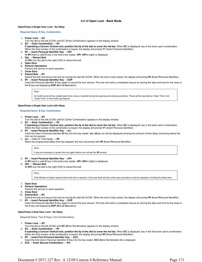
4.2.12 Open Lock - Bank Mode
Open/Close a Single User Lock - No Delay
Required Items: B Key, Combination
1. Power Lock → EC Turn the dial to the left (CCW) until EC (Enter Combination) appears in the display window.
2. EC → Enter Combination → IPI If operating a Cencon Vertical lock, position the lip of the dial to cover the red bar. When EC is displayed, key in the bank user's combination. When the final number of the combination is keyed, the display will prompt IPI (Insert Personal Identifier).
3. IPI → Insert Personal Identifier Key → OPr At IPI insert a valid B key in the lock's key reader. OPr (OPen right) is displayed.
4. Opr → Retract Bolt At OPr turn the dial to the right (CW) to retract the bolt.
5. Open Door 6. Perform Operations
Perform the service or bank operation. 7. Close Door 8. Extend Bolt → IPI
Extend the bolt and secure the lock by turning the dial left (CCW). When the lock is fully locked, the display will prompt IPI (Insert Personal Identifier). 9. IPI → Insert Personal Identifier Key → EOP
Insert the Personal Identifier B Key again to record the lock closure. The lock will verify a completed closure by storing the date and time for the close in the B key and displaying EOP (End of Operation).
Note
An Audit record will be created each time a key is inserted during the opening and closing operations. These will be reported as “Open Time” and “Close Time” on the Audit Log Reports.
Open/Close a Single User Lock with Delay
Required Items: B Key, Combination
1. Power Lock → EC Turn the dial to the left (CCW) until EC (Enter Combination) appears in the display window.
2. EC → Enter Combination → IPI If operating a Cencon Vertical lock, position the lip of the dial to cover the red bar. When EC is displayed, key in the bank user's combination. When the final number of the combination is keyed, the display will prompt IPI (Insert Personal Identifier).
3. IPI → Insert Personal Identifier Key → dxx Insert the User’s Personal Identifier B Key into the key reader. dxx (delay xx) will be displayed showing the amount of time delay remaining before the lock can be opened.
4. dxx → Wait for Time Delay → IPI When the programmed delay time has elapsed, the lock will prompt with IPI (Insert Personal Identifier).
Note
It may be necessary to power the lock again before you will get the IPI prompt.
5. IPI → Insert Personal Identifier Key → OPr At IPI insert a valid B key in the lock's key reader. OPr (OPen right) is displayed.
6. OPr → Retract Bolt At OPr turn the dial to the right (CW) to retract the bolt.
Note
If the Window to Open expires before the lock is opened, it will reset itself and the entire open procedure must be repeated, including the delay time.
7. Open Door 8. Perform Operations
Perform the service or bank operation. 9. Close Door
10. Extend Bolt → IPI Extend the bolt and secure the lock by turning the dial left (CCW). When the lock is fully locked, the display will prompt IPI (Insert Personal Identifier).
11. IPI → Insert Personal Identifier Key → EOP Insert the Personal Identifier B Key again to record the lock closure. The lock will verify a completed closure by storing the date and time for the close in the B key and displaying EOP (End of Operation).
Open/Close a Dual User Lock - No Delay
Required Items: Two B Keys, Two Combinations
1. Power Lock → EC Turn the dial to the left (CCW) until EC (Enter Combination) appears in the display window.
2. EC → Enter Combination → IPI If operating a Cencon Vertical lock, position the lip of the dial to cover the red bar. When EC is displayed, key in the first bank user's combination. When the final number of the combination is keyed, the display will prompt IPI (Insert Personal Identifier).
3. IPI → Insert First Personal Identifier Key → EC2 Insert the first User's Personal Identifier B Key into the key reader. EC2 (Enter Combination 2) is displayed.
4. EC2 → Enter Second Combination → IP2
Page 171Document # 2071.127 Rev. A 12/09 Cencon 4 Reference Manual

Key in the combination for the second User. IP2 (Insert Personal Identifier 2) is displayed.. 5. IPI → Insert Second Personal Identifier Key → OPr
Insert the second User’s Personal Identifier B key into the key reader. OPr (OPen right) is displayed. 6. OPr → Retract Bolt
At OPr turn the dial to the right (CW) to retract the bolt. 7. Open Door 8. Perform Operations
Perform the service or bank operation. 9. Close Door
10. Extend Bolt → IP? Extend the bolt by turning the dial to the left (CCW) until IP? (Insert Personal Identifier ?, either 1 or 2) is displayed.
11. IP? → Insert Personal Identifier Key → EOP Insert either User’s Personal Identifier B Key into the key reader. The lock will confirm the closure by writing the date and time of the close into the B key and displaying EOP (End of Operation).
Note (Gen 1 locks only)
If you experience a lockout situation with dual user access, you should be aware that user order on a retry is important. After the lockout period expires, the lock will open if the first combination and the first key used in the current entry attempt are the same as those used during the entry attempt that caused the lockout. If the first combination and the first key used are not the same as those used when the lockout occurred, the lock will prompt with IP2 and will then prompt with EC2. This requirement does not apply to Gen 2 locks.
Open/Close a Dual User Lock with Delay
Required Items: Two B Keys, Two Combinations
1. Power Lock → EC Turn the dial to the left (CCW) until EC (Enter Combination) appears in the display window.
2. EC → Enter Combination → IPI If operating a Cencon Vertical lock, position the lip of the dial to cover the red bar. When EC is displayed, key in the first bank user's combination. When the final number of the combination is keyed, the display will prompt IPI (Insert Personal Identifier).
3. IPI → Insert First Personal Identifier Key → EC2 Insert the first User's Personal Identifier B Key into the key reader. EC2 (Enter Combination 2) is displayed.
4. EC2 → Enter Second Combination → IP2 Key in the combination for the second User. IP2 (Insert Personal Identifier 2) is displayed..
5. IPI → Insert Second Personal Identifier Key → dxx Insert the second User’s Personal Identifier B key into the key reader. dxx (delay xx), with xx being the time delay remaining before the lock can be opened, is displayed.
6. dxx → Wait for Time Delay → IPI When the programmed delay time has elapsed, the lock will prompt with IPI (Insert Personal Identifier).
Note
It may be necessary to power the lock again before you will get the IPI prompt.
7. IPI → Insert First Personal Identifier Key → IP2 Insert the first User’s Personal Identifier B key into the key reader. IP2 (Insert Personal Identifier 2) is displayed.
8. IPI → Insert Second Personal Identifier Key → OPr Insert the second User’s Personal Identifier B key into the key reader. OPr (OPen right) is displayed.
9. OPr → Retract Bolt At OPr turn the dial to the right (CW) to retract the bolt.
Note
If the Window to Open expires before the lock is opened, it will reset itself and the entire open procedure must be repeated, including the delay time.
10. Open Door 11. Perform Operations
Perform the service or bank operation. 12. Close Door 13. Extend Bolt → IP?
Extend the bolt by turning the dial to the left (CCW) until IP? (Insert Personal Identifier ?, either 1 or 2) is displayed. 14. IP? → Insert Personal Identifier Key → EOP
Insert either User’s Personal Identifier B Key into the key reader. The lock will confirm the closure by writing the date and time of the close into the B key and displaying EOP (End of Operation).
Note
If you experience a lockout situation with dual user access, you should be aware that user order on a retry is important. After the lockout period expires, the lock will open if the first combination and the first key used in the current entry attempt are the same as those used during the entry attempt that caused the lockout. If the first combination and the first key used are not the same as those used when the lockout occurred, the lock will prompt with IP2 and will then prompt with EC2.
Page 172Document # 2071.127 Rev. A 12/09 Cencon 4 Reference Manual

4.2.13 Bank Mode - Add Users
Open/Close a Single User Lock - No Delay
Required Items: B Key, Combination, Change Key, SA Key
1. Power Lock → EC Turn the dial to the left (CCW) until EC (Enter Combination) appears in the display window.
2. EC → Enter Combination → IPI If operating a Cencon Vertical lock, position the lip of the dial to cover the red bar. When EC is displayed, key in the bank user's combination. When the final number of the combination is keyed, the display will prompt IPI (Insert Personal Identifier).
3. IPI → Insert Personal Identifier Key → OPr At IPI insert a valid B key in the lock's key reader. OPr (OPen right) is displayed.
4. OPr → Retract Bolt At OPr turn the dial to the right (CW) to retract the bolt.
5. Open Door 6. Insert Change Key
Insert the change key into the change key socket. 7. Extend Bolt
With the door open, extend the bolt.
8. Power Lock →
Turn the dial to the left (CCW) until (Change Key Symbol along with Enter Combination) appears on the display.
9. → Enter Default Combination → ISA
If operating a Cencon Vertical lock, position the lip of the dial to cover the red bar. When EC is displayed, Enter the default factory combination of 50-25-50. ISA (Insert Supervisor Audit Key) will be displayed.
10. ISA → Insert and Hold SA Key → Add Insert and hold the SA key in the key reader on the side of the lock. The lock will display Add (Adding Users) while the information is being processed.
11. Add → POC Continue to hold the SA Key in the reader until POC (Pull Out Change Key) is displayed.
12. POC → Remove SA Key and Pull Out Change Key → OPr Remove the SA key and the change Key. OPr (OPen right) will be displayed.
13. OPr → Retract Bolt Turn the dial to the right (CW) to retract the bolt. Adding Users is now complete for the Users that were programmed into the SA key.
14. Close Door 15. Extend Bolt → IPI
Extend the bolt by turning the dial to the left (CCW). IPI (Insert Personal Identifier) will be displayed. 16. IPI → Insert Personal Identifier Key → EOP
Insert the User’s Personal Identifier B Key into the key reader again. The lock will confirm the closure by writing the date and time of the close into the B key and displaying EOP (End of Operation).
Note
After adding a User you will need to change the combinations for the User that was added. All Bank User combinations are initially set to the default combination of 50-25-50 but will not open the lock until changed to a valid new combinations.
Note
If the lock is in dual mode and a bank user is forced to change their combo, the dual combo entry process is aborted. When the user's combo is successfully changed, the lock indicates the end of the operation (EOP).
Page 173Document # 2071.127 Rev. A 12/09 Cencon 4 Reference Manual

4.2.14 Bank Mode - Remove Users
Follow this procedure to delete Users from the lock at the lock after deleting them from the PC System:
Required Items: B Key, Combination, Change Key, SA Key
1. Power Lock → EC Turn the dial to the left (CCW) until EC (Enter Combination) appears in the display window.
2. EC → Enter Combination → IPI If operating a Cencon Vertical lock, position the lip of the dial to cover the red bar. When EC is displayed, key in the bank user's combination. When the final number of the combination is keyed, the display will prompt IPI (Insert Personal Identifier).
3. IPI → Insert Personal Identifier Key → OPr At IPI insert a valid B key in the lock's key reader. OPr (OPen right) is displayed.
4. Opr → Retract Bolt At OPr turn the dial to the right (CW) to retract the bolt.
5. Open Door 6. Insert Change Key
Insert the change key into the change key socket. 7. Extend Bolt
With the door open, extend the bolt.
8. Power Lock →
Turn the dial to the left (CCW) until (Change Key Symbol along with Enter Combination) appears on the display.
9. → Enter Default Combination → ISA
If operating a Cencon Vertical lock, position the lip of the dial to cover the red bar. When EC is displayed, Enter the default factory combination of 50-25-50. ISA (Insert Supervisor Audit Key) will be displayed.
10. ISA → Insert and Hold SA Key → dEL Insert and hold the SA key in the key reader on the side of the lock. The lock will display dEL (dELeting Users) while the information is being processed.
11. dEL → POC Continue to hold the SA Key in the reader until POC (Pull Out Change Key) is displayed.
12. POC → Remove SA Key and Pull Out Change Key → OPr Remove the SA key and the change Key. OPr (OPen right) will be displayed.
13. OPr → Retract Bolt Turn the dial to the right (CW) to retract the bolt. Deleting Users is now complete for the Users that were programmed into the SA key.
14. Close Door 15. Extend Bolt → IPI
Extend the bolt by turning the dial to the left (CCW). IPI (Insert Personal Identifier) will be displayed. 16. IPI → Insert Personal Identifier Key → EOP
Insert the User’s Personal Identifier B Key into the key reader again. The lock will confirm the closure by writing the date and time of the close into the B key and displaying EOP (End of Operation).
Warning
If the lock is only activated in Bank Mode, do not delete all users!
Page 174Document # 2071.127 Rev. A 12/09 Cencon 4 Reference Manual

4.2.15 Bank Users - Change Combination
The combination for a Bank User can be changed whenever desired. It is recommended that the combination be changed periodically to maintain a high level of security. To change the combination:
Required Items: B Key, Current Combination
1. Power Lock → EC Power the lock by turning the dial to the left (CCW) until EC (Enter Combination) is displayed.
2. EC → Press #8 → IPI Press the # button followed by 8. IPI (Insert Personal Identifier) is displayed.
3. Note
To determine the code level of your lock, see Appendix E.
For Locks with Code Level 64B and below:
4. IPI → Insert 01 Personal Identifier Key → bc xxxxxx Insert User 01’s Personal Identifier B Key into the key reader. The lock will display bc (bank combination) followed by the new combination, displayed two digits at a time.
5. bc xxxxxx → Record Combination and Press * → cc Record the combination for User 01 and press * to acknowledge receipt of new combination. The display will prompt cc (confirm combination).
6. cc → Enter New Combination → EOP Enter the new combination by pressing those digits on the lock’s keypad. The numbers will be displayed as they are entered. EOP (End OPeration) will be displayed. The newly confirmed combination is now active for that Bank User and Personal Identifier Key.
Note
If a flashing lightning bolt appears on the display, the combination was not confirmed properly. Reset by pressing the “*” key and rekey the operation.
For Locks with Code Level 65B and above:
4. IPI → Insert Personal Identifier Key → EcC Insert the User's Personal Identifier B Key into the key reader. The lock will display EcC (Enter current Combination).
5. EcC → Enter current Combination → EnC Enter the user's current combination. The display will display EnC (Enter new Combination).
Warning
For security purposes, you should define your own values for User Combinations in your Cenbank system.
6. EnC → Enter New Combination → CnC Enter the new combination on the lock’s keypad. The numbers are displayed as they are entered. CnC (Confirm new Combination) will be displayed.
7. CnC → Confirm New Combination → EOP Enter the new combination again by pressing those digits on the lock’s keypad. The numbers will be displayed as they are entered. EOP (End OPeration) will be displayed. The newly confirmed combination is now active for that Bank User and Personal Identifier Key.
Note
Note: If a flashing lightning bolt appears on the display, the combination was not confirmed properly. Reset by pressing the “*” key and rekey the operation.
4.2.16 Set the Lock Time
An initialized DS1922 key is required to set the time in a lock (Gen2).
Required Items: Initialized DS1922 Key
1. Power Lock → EC Turn the dial to the left (CCW) until EC (Enter Combination) appears in the display window.
2. EC → Press #0 →-dL Press the pound (#) button followed by the 0 button. -dL will be displayed.
Note
If the lock has sufficient power, the #0 will go directly to ISA without the -dL indicated in steps 2 and 3.
3. -dL → ISA Turn the dial to the left (CCW) until ISA is displayed.
4. ISA → Insert and Hold DS1922 Key → CLS Insert and hold the initialized DS1922 key in the lock's key reader. The lock will display CLS (CLock Set in Progress) while the clock is being set and the daylight savings time information is being saved.
Page 175Document # 2071.127 Rev. A 12/09 Cencon 4 Reference Manual

Note
You may need to turn the dial to maintain power during this time.
5. CLS → EOP Continue to hold the key in the reader until EOP (End OPeration) is displayed.
6. EOP → Remove Key When the display prompts EOP, remove the DS1922 key.
Note
The clock set key is not lock specific and may be reused to set the time on additional locks.
Page 176Document # 2071.127 Rev. A 12/09 Cencon 4 Reference Manual

4.2.17 Retrieve Bank Users From Lock
It is possible to use an initialized Supervisor Audit key to retrieve a list of the bank users from a Cencon Gen2 lock. The information is downloaded from the lock into the SA key, which is then returned to the Cencon dispatch center. The information in the key can then be viewed using the Cencon Key Report function. To retrieve the list of bank users assigned to the lock:
Required Items: Initialized Red SA Key
1. Power Lock → EC Turn the dial to the left (CCW) until EC (Enter Combination) appears in the display window.
2. EC → Press #0 →-dL Press the pound (#) button followed by the 0 button. -dL will be displayed.
Note
If the lock has sufficient power, the #0 will go directly to ISA without the -dL indicated in steps 2 and 3.
3. -dL → ISA Turn the dial to the left (CCW) until ISA is displayed.
4. ISA → Insert and Hold SA Key → UdP Insert and hold the initialized SA key in the lock's key reader. The lock will display UdP (User dumP in progress) while the user retrieval is being processed.
Note
You may need to turn the dial to maintain power during this time.
5. UdP → EOP Continue to hold the SA Key in the reader until EOP (End OPeration) is displayed.
6. EOP → Remove SA Key When the display prompts EOP, remove the SA key.
7. Return SA Key Return the SA Key to the dispatch center to be read using the Cencon Key Report function.
4.2.18 Resynchronize the Database with a Lock
It is possible to use an initialized DS1963 key to retrieve the status of Cencon Gen2 lock. The lock status information is downloaded from the lock into the DS1963 key, which is then returned to the Cencon dispatch center and used to update the Cencon database.
Required Items: Initialized Grey Resynchronization Key
1. Power Lock → EC Turn the dial to the left (CCW) until EC (Enter Combination) appears in the display window.
2. EC → Press #0 →-dL Press the pound (#) button followed by the 0 button. -dL will be displayed.
Note
If the lock has sufficient power, the #0 will go directly to ISA without the -dL indicated in steps 2 and 3.
3. -dL → ISA Turn the dial to the left (CCW) until ISA is displayed.
4. ISA → Insert and Hold DS1963 Key → rSY Insert and hold the initialized key in the lock's key reader. The lock will display rSY ( reSYnchronization in Progress) while the lock data retrieval is being processed.
Note
You may need to turn the dial to maintain power during this time.
5. rSY → EOP Continue to hold the Key in the reader until EOP (End OPeration) is displayed.
6. EOP → Remove Key When the display prompts EOP, remove the key.
7. Return Key Return the Key to the dispatch center to be read using the Resynchronize the Database with Lock Data operation.
Page 177Document # 2071.127 Rev. A 12/09 Cencon 4 Reference Manual

4.2.19 Display Lock Level
It is sometimes necessary to determine the code level of the Cencon Lock with which you are working. This can be done through the keypad with the level displayed on the LCD. Use the following procedure:
1. Power Lock → EC Power the Lock by turning the dial to the left (CCW) until EC appears in the display window.
2. EC → Press #1 Press # followed by 1.
All Gen 2 locks will display “LL-” , “G2”, followed by 4 sets of 3 numbers, followed by “HL-” with 2 number pairs.
If the LCD instead shows the letters “LL-” followed by a string of number pairs then “HL-” followed by 2 number pairs, then this lock is a Gen1 lock.
Note
To determine the exact Lock Level of a Gen 1 lock, please refer to Appendix F of the Cencon Reference Manual. 4.
The lock will continue repeating the Lock Level until either the * key is held down or until the dial has not been turned in 40 seconds.
4.2.20 Gen2 Lock Menu Prompts
The Gen 2 lock allows the user to gather additional information in the field simply by pressing keypad commands, sometimes presenting their user key, and then reading the LCD. For each of the commands that displays either current or historic Date and Time (#71, #72, #78, and #79), the format is the same: Starting from the largest time increment (4-digit Year) and moving down to the smallest (2-digit second). For readability, the date and the time are broken apart by the “Hr-” (hour) prompt in the middle.
All the prompts that request a user key (blue FLM, yellow Route, or green Bank) be presented will do so by displaying the “IPI” after the command is entered. The difference to note is that #73 will be reading and displaying information unique to a particular key, whereas #72, #76, #78, and #79 are reading which particular mode this key is associated with (FLM, Route, or Bank) and then displaying information for that entire mode.
As is the case with interacting with the other prompts, the information will continue to display to the user until the lock powers down or until the * is held down.
#70: Display active modes and activator identification
Without requiring a user key or an audit key, it is possible to determine the following:
Which modes on the lock are currently active: FL (First Line Maintenance), ro (Route), or bA (Bank mode). Whether this mode is active in Single or Dual access, noted by either a 1 or 2 before the mode abbreviation.
If the activating company activated their mode using a USB Key Box and the 4.0 or higher software, additional security benefits are incorporated in the lock. One example is that the #70 also would display the following (rather than displaying only 0’s if the customer activated the lock with a version below 4.0 or with a PCI card system.):
A unique 4-digit code (Cn-) assigned by Kaba Mas for the company that has activated that mode, in order that vendors sharing access might know who to contact for service needs at the ATM, Which USB Key Box 4-digit number (bn-) assigned to that particular customer, created the activation key, in order for tracking and to deter possible security violations.
(For example, “01-“, “1FL”, “ Cn”, “ 00”, “ 00”, “ bn”, “ 00”, “ 00”, “02-“, “1ro”, “ Cn”, “ 00”, “ 00”, “ bn”, “ 00”, “ 00”, “03-“, “2bA”, “ Cn”, “ 00”, “ 00”, “ bn”, “ 00”, “ 00”, where “FL” indicates FLM mode, “ro” indicates route mode, “bA” indicates bank mode, the “1” prefix indicates single mode, the “2” prefix indicates dual mode, the “ Cn” prompt precedes the company code, and “ bn” precedes the USB key box device ID)
#71: Display internal UTC/GMT date/time
Each Gen 2 lock is programmed to the current UTC/GMT date/time when the lock is manufactured at Kaba Mas (For example, “UtC”, “Yr-”, “ 20”, “ 09”, “ 12”, “ 25”, “Hr-”, “ 22”, “ 30”, “ 59”),
#72: Display the local date/time by user key
If a customer uses Cencon 4.0 with a USB Box with their Gen2 lock, the lock will store which the TimeZone information, for that particular company, in order that they might use Time Windows for their user keys. This also allows this customer to check the local time setting for this lock, which simply adjusts the internal GMT clock with the time zone information (For example, “LCL”, “Yr-”, “ 20”, “ 09”, “ 12”, “ 25”, “Hr-”, “ 17”, “ 30”, “ 59”).
#73: Display key type and key serial number for the key presented
Each SmartKey has a unique serial number engraved on the key, which is also recorded in the Cencon software when that key is added to the customer’s database. At times in the field, to troubleshoot and to ensure that the user has the appropriate key that the combination was dispatched to, it may be necessary to relay the key serial number over the phone back to the dispatcher. The #73 function of the Gen2 lock allows any user key to be presented to the lock’s key reader to display the key serial number which assists the user in this serial number’s legibility. The serial number typically starts with 6 zeros, and then has 6 alpha-numeric characters, including letters A-F. (For example, “CL-”, “14”, “27”, “CS-”, “00”, “00”, “00”, “11”, “d7”, “EF”, to display the iButton device number and 12 digit serial number.)
#74: Display door contact switch status
The Gen2 lock has a 4-pin alarm input cable to optionally use Door Contact switches and for a Remote Disable function. After installing the door contact switches, the customer will want to determine the status of these sensor, often while the lock is still in factory mode, and later when the lock is activated (For example, “OPd” for “OPened door”, “CLd” for “closed door”, or “nCC” for “no door contact connection” accordingly).
Page 178Document # 2071.127 Rev. A 12/09 Cencon 4 Reference Manual

#76: Display software level the mode was activated with by user key
Because the Gen2 lock will incorporate many more security and functional enhancements as well as future compatibility allowances when the lock used in conjunction with the Cencon 4.0 or higher software + the USB Key Box, it is important for a customer in the field to know whether or not the mode being used has been programmed with this updated settings (For example, “SL-“, “ 01”, where software level "01" is compatibility mode, and software level "02" indicates Cencon 4.0 or higher with a USB Key Box).
#77: Display UTC/GMT date/time on DS1994 FLM and Route keys and DS1427 Bank Keys
Even though the Gen2 lock no longer uses the internal iButton timekeeping registers on DS1994 FLM and Route keys or from DS1427 Bank keys, that time can be now be read at the Gen2 lock for diagnosing problems encountered when operating Gen1 locks. The time is displayed in UTC/GMT format since time zone information may not be available to Gen2 locks operating in compatibility mode. (For example, “PIC”, “Yr-”, “ 20”, “ 09”, “ 10”, “ 31”, “Hr-”, “16”, “ 45”, “ 00”).
#78: Display last opening local date/time by user key
For purposes of quick minimal auditing of a lock in a field, the Gen2 lock will display the last opening date and time (in that customer’s local time setting) by presenting that mode’s key (For example, “LOP”, “Yr-”, “ 20”, “ 09”, “ 10”, “ 31”, “Hr-”, “ 16”, “ 45”, “ 00”).
#79: Display activation local date/time by user key
For purposes of determining when a mode was activated, without the necessity of using an audit key and software, the Gen2 lock will display the date and time of the current activation by that mode if a user key from that mode’s system is presented (For example, “ACt”, “Yr-”, “ 20”, “ 09”, “ 10”, “ 21”, “Hr-”, “ 13”, “ 30”, “ 05”).
Page 179Document # 2071.127 Rev. A 12/09 Cencon 4 Reference Manual
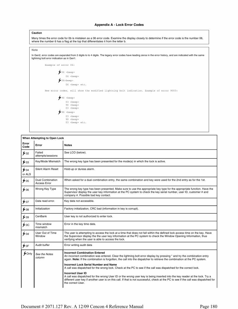
Appendix A - Lock Error Codes
Caution
Many times the error code for 0b is mistaken as a 06 error code. Examine the display closely to determine if the error code is the number 06, where the number 6 has a flag at the top that differentiates it from the letter b.
Note
In Gen2, error codes are expanded from 2 digits to to 4 digits. The legacy error codes have leading zeros in the error history, and are indicated with the same lightning bolt error indication as in Gen1.
Example of error 06:
06 <beep>
06 <beep>
06<beep>
06 <beep> etc. New error codes, will show the modified lightning bolt indication. Example of error 9003:
90 <beep>
03 <beep> 90 <beep> 03 <beep>
90 <beep>
03 <beep> 90 <beep> 03 <beep> etc.
When Attempting to Open Lock
Error Code Error Notes
02 Failed attempts/sessions
See LCO (below).
03 Key/Mode Mismatch The wrong key type has been presented for the mode(s) in which the lock is active.
04
or ALS
Silent Alarm Reset Hold-up or duress alarm.
05 Dual Combination Access Error
When asked for a dual combination entry, the same combination and key were used for the 2nd entry as for the 1st.
06 Wrong Key Type The wrong key type has been presented. Make sure to use the appropriate key type for the appropriate function. Have the Supervisor display the user key information at the PC system to check the key serial number, user ID, customer # and company #. Possible bad key contact.
07 Data read error. Key data not accessible.
08 Initialization Factory initialization, CRC bad (information in key is corrupt).
09 CenBank User key is not authorized to enter lock.
0C Time window mismatch
Error in the key time data.
0d User Out of Time Window
The user is attempting to access the lock at a time that does not fall within the defined lock access time on the key. Have the Supervisor display the the user key information at the PC system to check the Window Opening Information, thus verifying when the user is able to access the lock.
0F Audit buffer Error writing audit data
Only See the Notes column
Incorrect Combination Entered An incorrect combination was entered. Clear the lightning bolt error display by pressing * and try the combination entry again. Note: If the combination is forgotten, the call into the dispatcher to retrieve the combination at the PC system.
Incorrect Lock Serial Number and Name A call was dispatched for the wrong lock. Check at the PC to see if the call was dispatched for the correct lock.
Incorrect User ID A call was dispatched for the wrong User ID or the wrong user key is being inserted into the key reader at the lock. Try a different user key if another user is on this call. If that is not successful, check at the PC to see if the call was dispatched for the correct User.
Page 180Document # 2071.127 Rev. A 12/09 Cencon 4 Reference Manual

Audit count mismatch The audit count in the lock does not match the lock audit count in software at the PC. If the count is higher at the lock, use the user key to get the last close seal from lock and call it in to the PC. If the audit count is higher at the PC, get the next to last combo and use it along with the appropriate user key to open and close the lock. It is not necessary to report the close seal at this point since the call has already been closed at the PC.
LCO 5 Failed Lock Entry Attempts
The combination was entered incorrectly 5 times. The lock has now gone into a "lockout" mode. Review the items in the previous section (Lightning Bolt Only) to try and determine the cause for the failed attempts.
Wait at least 4.5 minutes without powering the lock and then enter a valid combination and present the appropriate key.
Gen2 Locks If there is a problem with the battery in the Gen2 lock when a lockout occurs, the lock must have power for the full timeout period. The display will alternately flash -dL and LCO to indicate this.
When Attempting to Activate/Shelve Lock with SA Key
Error Code
Error Notes
03Lock Mode Mismatch
The lock is already active in the mode that you are attempting to activate.
06 See the Notes column
Wrong Key Type The wrong key type has been presented. Make sure to use the appropriate key type for the appropriate function.
Unable to Read SA Key Information There is no information in the key or the key has been bounced and the the key is corrupt. If the audit count at the lock and the PC match, use combination. Otherwise contact Kaba Mas Customer Service at 1(800) get a close seal and try operation again with a re-programmed key
09 CenBank Lock is already active in CenBank mode.
0A See the Notes column
Last Audit Record not "Open" An attempt is being made to activate or shelve the lock but the last record showing in the Audit trail is not an "Open". This might be caused by the the bolt being extended before the Change Key is inserted. If the lock is in Shelved Mode, enter the Shelved Mode combination, retract the bolt, insert the Change Key and continue with the procedure. If the lock is active in another mode, close the call and have another call dispatched to open the lock and insert the Change Key and then continue with the procedure.
Lock Mode Already Active/Shelved The lock is already active or shelved in the mode you are trying to activate or shelve.
0b Bad Processor Reset
An internal error has occurred while trying to reset the processor in the lock. Clear the lightning bolt error display by pressing * and try the operation again (note that these failures are counted toward the five entry attempt limit).
If you continue to get the error indicator, contact Kaba Mas Customer Service for assistance at 1(800) 950-4744 .
Lock Read/Write
Error Code Error
60 Eprom factory initialize.
61 Drill.
62 Eprom housekeeping Write.
63 One mode of the lock is corrupted. Try another and and remove from service. If all modes give 63 Drill. If powers up 63 then Drill.
64 Eprom Cust. Initialize.
65 Eprom Error List Read.
66 Eprom Error List Write.
67 One mode of the lock is corrupted. Try another mode and remove from service. If all modes give 67 drill. If powers up 67 then Drill.
68 Eprom SMCS Write.
69 Eprom Bank User Read (Lock could not read the key to memory).
6A Eprom Bank User Write (Lock could not write the opening into memory).
6b Occurs with older model of lock. User key-different key closing lock than which opened the lock. Some are key specific some are mode specific.
6C One mode of the lock is corrupted. If all modes give 6C drill. Try another mode once opened remove from service. If powers up 6C then Drill.
6d One mode of the lock is corrupted. If all modes give 6C drill. Try another mode once opened remove from service. If powers up 6C then Drill.
Page 181Document # 2071.127 Rev. A 12/09 Cencon 4 Reference Manual

6E Eprom Delay-Data Write.
6F Eprom Factory Initialize Read.
Key Read/Write
Error Code
Error
71 Key is dead. Issue new key.
72 Touch Memory – House Keeping Write
73 Bad time in the key. Verify audit, lock will be one ahead. Close and issue new combo to that key for that lock and have the tech open and get close. It will correct the time in the key.
74 Bad key Contact, Try again and if the error still appears clean key and key reader.
75 Touch Memory – Initialize/ Shelve Rec1 Read.
76 Only while supershelving, shelving or activating. Is like a 7F for a supershelve/SA key. Use supershelve key again within 6 seconds and finish.
77 Touch Memory - Initialize Rec2 Read.
78 Touch Memory - Initialize Rec2 Write.
79 Touch Memory-Initialize RecX Read.
7A Touch Memory- Initialize Recx Write.
7b Touch Memory- Supershelve Read.
7C Touch Memory- Supershelve.
7d Touch Memory - Cannot read the key.
7E Error reading/writing Time Window record (Out of time windows).
7F Bad key Contact, try again.
Gen2 Codes
Error Code Error
9003 Time windows user denied access due to clock failed/reset condition.
9005 iButton family code lookup error.
9006 Audit key was not formatted for a Gen2 lock.
9007 Clock failed.
96nn Memory error.
97nn iButton error
9B00 Lock firmware error.
Page 182Document # 2071.127 Rev. A 12/09 Cencon 4 Reference Manual

Appendix B - Lock Keypad Commands
Below is a list of the various Keypad Commands that are accessed beginning with the (#) symbol. For more detail on each of the lock operations, refer to the section Lock Operations.
Details on the #55 display:
In Gen 1, the display format is "Er-", "00", "00", ... , "00" | | | Error Error Error Code Code Code #1 #2 #15 In Gen 2, the display format is "Er-", "00", "00", ... , "00", "00" \_______/ \________/ | | Error Error Code Code #1 #15
NOTE: In Gen 2, error codes are expanded from 2 digits to to 4 digits.
Command Function
# # Display Mode’s Audit Count (opening count) by user key.
# 0 Perform administrative operations. (audit download, resync, clock set, bank user table download, etc.)
# 1 Display lock code and hardware levels.
# 2 Display Lock Serial Number.
# 3 Display lock opening odometer (Total Audit Count)
# 4 Get last close seal, based on user key’s mode
# 6 Reserved.
# 8 Change shelved-mode combination or bank user’s combination.
# 9 Reserved.
# 55 Displays a list of the last 15 error codes
# 70 Gen 2: Display active modes and identification of the activating company
# 71 Gen 2: Display the base UTC/GMT date and time
# 72 Gen 2: Display the local date and time according to user key’s mode
# 73 Gen 2: Display key type and key serial number for the key presented.
# 74 Gen 2: Display door contact switch status.
# 76 Gen 2: Display software level the mode was activated with by user key.
# 77 Gen 2: Display internal UTC/GMT key time on DS1994 FLM and Route and DS1427 Bank keys
# 78 Gen 2: Display last opening local date/time by user key’s mode
# 79 Gen 2: Display activation local date/time by user key’s mode
Page 183Document # 2071.127 Rev. A 12/09 Cencon 4 Reference Manual

Appendix C - Lock Displays and Prompts
The Cencon front cover LCD uses a 7-segment font, displaying up to 3 characters at a time. Some prompts will show a mixture of numbers and letters. Also, since some letters are only distinguishable in their capital form and other letters in their lower-case form, the LCD will show a mixture of both types at once.
Samples:
Displays while Audit data is being written.
close Seal Number
Enter Combination
Enter Combination 2
Enter Combination to Change using Change Key
End OPeration
Initializing
Page 184Document # 2071.127 Rev. A 12/09 Cencon 4 Reference Manual

Insert Personal Identifier
Insert Personal Identifier 2
Insert Supervisor Audit Key
LoCk Out in Effect, Lock Disabled
Open right
Pull out change key
replace Personal Identifier (In Dual Mode - insert other key.)
SheLving
Page 185Document # 2071.127 Rev. A 12/09 Cencon 4 Reference Manual
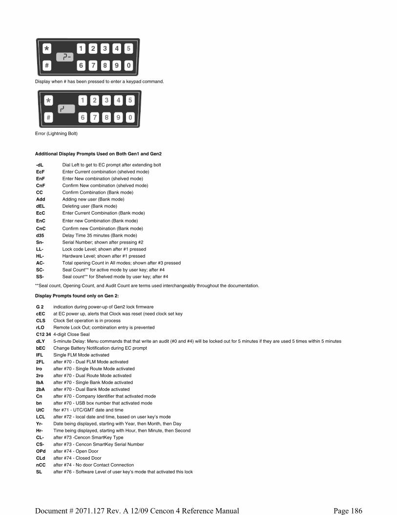
Display when # has been pressed to enter a keypad command.
Error (Lightning Bolt)
Additional Display Prompts Used on Both Gen1 and Gen2
**Seal count, Opening Count, and Audit Count are terms used interchangeably throughout the documentation.
Display Prompts found only on Gen 2:
-dL Dial Left to get to EC prompt after extending bolt
EcF Enter Current combination (shelved mode)
EnF Enter New combination (shelved mode)
CnF Confirm New combination (shelved mode)
CC Confirm Combination (Bank mode)
Add Adding new user (Bank mode)
dEL Deleting user (Bank mode)
EcC Enter Current Combination (Bank mode)
EnC Enter new Combination (Bank mode)
CnC Confirm new Combination (Bank mode)
d35 Delay Time 35 minutes (Bank mode)
Sn- Serial Number; shown after pressing #2
LL- Lock code Level; shown after #1 pressed
HL- Hardware Level; shown after #1 pressed
AC- Total opening Count in All modes; shown after #3 pressed
SC- Seal Count** for active mode by user key; after #4
SS- Seal count** for Shelved mode by user key; after #4
G 2 indication during power-up of Gen2 lock firmware
cEC at EC power up, alerts that Clock was reset (need clock set key
CLS Clock Set operation is in process
rLO Remote Lock Out; combination entry is prevented
C12 34 4-digit Close Seal
dLY 5-minute Delay: Menu commands that that write an audit (#0 and #4) will be locked out for 5 minutes if they are used 5 times within 5 minutes
bEC Change Battery Notification during EC prompt
IFL Single FLM Mode activated
2FL after #70 - Dual FLM Mode activated
Iro after #70 - Single Route Mode activated
2ro after #70 - Dual Route Mode activated
IbA after #70 - Single Bank Mode activated
2bA after #70 - Dual Bank Mode activated
Cn after #70 - Company Identifier that activated mode
bn after #70 - USB box number that activated mode
UtC fter #71 - UTC/GMT date and time
LCL after #72 - local date and time, based on user key’s mode
Yr- Date being displayed, starting with Year, then Month, then Day
Hr- Time being displayed, starting with Hour, then Minute, then Second
CL- after #73 -Cencon SmartKey Type
CS- after #73 - Cencon SmartKey Serial Number
OPd after #74 - Open Door
CLd after #74 - Closed Door
nCC after #74 - No door Contact Connection
SL after #76 - Software Level of user key’s mode that activated this lock
Page 186Document # 2071.127 Rev. A 12/09 Cencon 4 Reference Manual

LOP after #78 - Last Opening date and time (local), based on user key
ACt after #79 - Activation date & time (local), of user key
UdP User Table Download (Bank Mode)
UPA Update Activation
rSY Re-Sync operation
Page 187Document # 2071.127 Rev. A 12/09 Cencon 4 Reference Manual

Appendix D - System Process Overview
Activate Lock in FLM or Route Mode from Shelved Mode
1. PROGRAM ACTIVATION SA KEY AT PC, THUS DISPATCHING F OR R KEY 2. TAKE ROUTE OR FLM KEY, SA KEY, CHANGE KEY AND COMBINATION TO LOCK 3. OPEN LOCK WITH SHELVED MODE COMBINATION 4. ACTIVATE LOCK WITH CHANGE KEY AND SA KEY 5. OPEN LOCK WITH F OR R KEY TO VERIFY ACTIVATION WAS SUCCESSFUL 6. REPORT CLOSE SEAL TO DISPATCHER AND RETURN SA KEY
Activate Lock in Bank Mode from Shelved Mode
1. PROGRAM ACTIVATION SA KEY AT PC 2. TAKE SA KEY AND CHANGE KEY TO LOCK 3. OPEN LOCK WITH SHELVED MODE COMBINATION 4. ACTIVATE LOCK WITH CHANGE KEY AND SA KEY 5. CHANGE AND TEST COMBINATION FOR A MINIMUM OF TWO USERS
Activate Lock in Route Mode from FLM Mode
1. PROGRAM ACTIVATION SA KEY AT PC, THUS DISPATCHING ROUTE KEY 2. DISPATCH SERVICE CALL COMBINATION TO FLM AT PC 3. TAKE ROUTE KEY, FLM KEY, SA KEY, CHANGE KEY AND COMBINATIONS TO LOCK 4. OPEN LOCK WITH FLM SERVICE CALL COMBINATION 5. ACTIVATE LOCK WITH CHANGE KEY AND SA KEY 6. OPEN LOCK WITH R KEY TO VERIFY ACTIVATION WAS SUCCESSFUL 7. REPORT ROUTE AND FLM CLOSE SEALS TO DISPATCHER(S) AND RETURN SA KEY
Activate Lock in FLM Mode from Route Mode
1. PROGRAM ACTIVATION SA KEY AT PC, THUS DISPATCHING FLM KEY 2. DISPATCH SERVICE CALL COMBINATION TO ROUTE PERSON AT PC 3. TAKE ROUTE KEY, FLM KEY, SA KEY, CHANGE KEY AND COMBINATIONS TO LOCK 4. OPEN LOCK WITH ROUTE COMBINATION 5. ACTIVATE LOCK WITH CHANGE KEY AND SA KEY 6. OPEN LOCK WITH F KEY TO VERIFY ACTIVATION WAS SUCCESSFUL 7. REPORT ROUTE AND FLM CLOSE SEALS TO DISPATCHER(S) AND RETURN SA KEY
FLM/Route Service Call
1. DISPATCH SERVICE CALL COMBINATION TO FLM OR ROUTE PERSON AT PC 2. TAKE SERVICE CALL COMBINATION AND USER KEY TO LOCK 3. OPEN LOCK WITH SERVICE CALL COMBINATION 4. PERFORM SERVICE OPERATIONS 5. CLOSE LOCK AND RETRIEVE CLOSE SEAL 6. REPORT CLOSE SEAL TO DISPATCHER
Multi-Lock Route
1. DISPATCH ROUTE COMBINATIONS TO ROUTE PERSON AT PC 2. TAKE ROUTE COMBINATIONS AND ROUTE KEY TO EACH LOCK ON ROUTE 3. OPEN EACH LOCK WITH ROUTE COMBINATION 4. PERFORM ROUTE OPERATIONS ON EACH LOCK 5. CLOSE LOCK AND RETRIEVE CLOSE SEAL AT EACH LOCK 6. REPORT CLOSE SEALS OR RETURN ROUTE KEY TO DISPATCHER FOR CALLS TO BE CLOSED
Retrieve AND Report on Audit Download from Lock
1. INITIALIZE SA KEY AT PC 2. TAKE SA KEY TO LOCK 3. RETRIEVE AUDIT DATA WITH SA KEY 4. RETURN SA KEY TO PC TO READ AUDIT INFORMATION
Shelve Lock in FLM Mode
1. PROGRAM SHELVING SA KEY AT PC, THUS DISPATCHING FLM KEY 2. TAKE FLM KEY, SA KEY AND SHELVING COMBINATION TO LOCK 3. OPEN LOCK WITH F KEY 4. SHELVE LOCK WITH SA KEY 5. REPORT CLOSE SEAL TO DISPATCHER 6. RETURN SA KEY TO PC TO VERIFY SHELVING
Shelve Lock in Route Mode
1. PROGRAM SHELVING SA KEY AT PC, THUS DISPATCHING ROUTE KEY 2. TAKE ROUTE KEY, SA KEY AND SHELVING COMBINATION TO LOCK 3. OPEN LOCK WITH R KEY
Page 188Document # 2071.127 Rev. A 12/09 Cencon 4 Reference Manual

4. SHELVE LOCK WITH SA KEY 5. REPORT CLOSE SEAL TO DISPATCHER 6. RETURN SA KEY TO PC TO VERIFY SHELVING
Page 189Document # 2071.127 Rev. A 12/09 Cencon 4 Reference Manual

Appendix E - System Process Detail
Activate Lock in FLM Mode (from shelved mode)
Part I: Activate the lock at the PC
Personnel: Logon User authorized to activate FLM locks Required items: SA Key (Red)
1. Select Lock Operations from the main window 2. Click OK on the search screen 3. Select Activate Lock from the Administration Menu 4. Select Add Lock 5. Click on the row added to the lock list to highlight it. 6. If desired, change the default name of the lock 7. Select the FLM mode you want to activate 8. Enter the lock serial number 9. Enter the Group Name if you are using lock groups
10. Enter any of the remaining optional information 11. Click on Add Lock to add more locks to the activation key 12. Select FLM as the type of user you want to test the activation of the lock. 13. Enter the User ID of the FLM user to be assigned for the activation or press the browse button to search for a user. 14. Insert an SA key into the key reader 15. Click on Activate Locks 16. Write down the activation combinations
PART II: ACTIVATE LOCK AT LOCK
Personnel: FLM User Required items: F Key, SA Key, Change Key, Activation combination
1. Power lock by turning dial CCW until EC is displayed 2. Enter shelved mode combination. OPr is displayed 3. Turn dial CW to retract bolt 4. Open door 5. Insert the change key 6. Do not close the door. Turn the dial CCW to extend the bolt until EC is displayed 7. Enter the shelved mode combination ISA is displayed. 8. Insert and hold the SA key in the reader until POC is displayed 9. Pull out the change key. OPr is displayed
10. Turn the dial CW to retract the bolt 11. Do not close the door. Turn the dial CCW to extend the bolt until EC is displayed 12. Enter the activation combination. IPI is displayed 13. Insert and hold the F Key in the key reader until OPr is displayed. 14. Turn the dial CW to retract the bolt 15. Close the door 16. Turn the dial CCW to extend the bolt until IPI is displayed 17. Insert and hold the F Key in the key reader until the close seal is displayed 18. Record the close seal 19. Report the close seal to the dispatcher 20. Return the SA key to the dispatcher
PART III: Close the call at the PC
Personnel: Logon User authorized to close FLM locks
1. At the main screen, click on Close Lock 2. Enter the lock name and close seal 3. Click on Close Lock
Alternate method:
1. Select the lock in the Lock Operations report
Page 190Document # 2071.127 Rev. A 12/09 Cencon 4 Reference Manual

2. Select Close from the Lock Operations menu 3. Enter the Close Seal and press Close Lock
***** END OF PROCESS *****
Page 191Document # 2071.127 Rev. A 12/09 Cencon 4 Reference Manual

Appendix E - System Process Detail
Activate Lock in Route Mode (from shelved mode)
Part I: Activate the lock at the PC
Personnel: Logon User authorized to activate Route locks Required items: SA Key (Red)
1. Select Lock Operations from the main window 2. Click OK on the search screen 3. Select Activate Lock from the Administration Menu 4. Select Add Lock 5. Click on the row added to the lock list to highlight it. 6. If desired, change the default name of the lock 7. Select the Route mode you want to activate 8. Enter the lock serial number 9. Enter the Group Name if you are using lock groups
10. Enter any of the remaining optional information 11. Click on Add Lock to add more locks to the activation key 12. Select Route as the type of user you want to test the activation.of the lock. 13. Enter the User ID of the Route user to be assigned for the activation or use the browse button to search for the user. 14. Insert an SA key in to the key reader 15. Click on Activate Locks 16. Write down the activation combinations
PART II: ACTIVATE LOCK AT LOCK
Personnel: Route Service person Required items: R Key, SA Key, Change Key, Activation combination
1. Power lock by turning dial CCW until EC is displayed 2. Enter shelved mode combination. OPr is displayed 3. Turn dial CW to retract bolt 4. Open door 5. Insert the change key 6. Do not close the door. Turn the dial CCW to extend the bolt until EC is displayed 7. Enter the shelved mode combination. ISA is displayed. 8. Insert and hold the SA key in the reader until POC is displayed 9. Pull out the change key. OPr is displayed
10. Turn the dial CW to retract the bolt 11. Do not close the door. Turn the dial CCW to extend the bolt until EC is displayed 12. Enter the activation combination. IPI is displayed 13. Insert and hold the R Key in the key reader until OPr is displayed. 14. Turn the dial CW to retract the bolt 15. Close the door 16. Turn the dial CCW to extend the bolt until IPI is displayed 17. Insert and hold the F Key in the key reader until the close seal is displayed 18. Record the close seal 19. Report the close seal to t he dispatcher 20. Return the SA key to the dispatcher
PART III: CLOSE SERVICE CALL AT PC
Personnel: Logon User authorized to close Route locks
1. At the main screen, click on Close Lock 2. Enter the lock name and close seal 3. Click on Close Lock
Alternate method:
Page 192Document # 2071.127 Rev. A 12/09 Cencon 4 Reference Manual

1. Select the lock in the Lock Operations report 2. Select Close from the Lock Operations menu 3. Enter the Close Seal and press Close Lock
***** END OF PROCESS *****
Page 193Document # 2071.127 Rev. A 12/09 Cencon 4 Reference Manual

Appendix E - System Process Detail
Activate Lock in Bank Mode (from shelved mode)
Part I: Activate the Lock at the PC
Personnel: Logon User authorized to activate Bank locks Required items: SA key (Red), Lock Serial Number, Bank Branch ID
1. Select Lock Operations from the main window 2. Click OK on the search screen 3. Select Activate Lock from the Administration Menu 4. Select Add Lock 5. Click on the row added to the lock list to highlight it. 6. If desired, change the default name of the lock 7. Select the Bank mode you want to activate 8. Enter the lock serial number 9. Enter the Group Name if you are using lock groups.
10. Enter any of the remaining optional information 11. Click on Add Lock to add more locks to the activation key 12. Select Bank Mode as the Dispatch Mode 13. Select a Bank Branch Name 14. Enter optional values for the time delay and open window 15. Click on the Bank Users tab 16. Add at least two bank users to the selected users list. 17. Insert an SA key into the key reader 18. Click on Activate Locks
Part II: Activate Lock at Lock
Personnel: Bank Supervisor Required items: SA Key, Change Key
1. Power lock by turning dial CCW until EC is displayed 2. Enter shelved mode combination. OPr is displayed 3. Retract bolt and open door 4. Insert the change key 5. Do not close the door. Turn the dial CCW to extend the bolt until EC is displayed 6. Enter the shelved mode combination ISA is displayed. 7. Insert and hold the SA key in the reader until POC is displayed 8. Pull out the change key. OPr is displayed 9. Turn the dial CW to retract the bolt
10. Close the door, Extend the bolt
***** END OF PROCESS *****
Page 194Document # 2071.127 Rev. A 12/09 Cencon 4 Reference Manual

Appendix E - System Process Detail
Activate Lock in Route Mode (Already in FLM Mode)
Part I: Activate the lock at the PC
Personnel: Logon User authorized to activate Route locks and dispatch FLM calls Required items: SA Key
1. Select Lock Operations from the main window 2. Click OK on the search screen 3. Select Activate Lock from the Administration Menu 4. Select Add Lock 5. Click on the row added to the lock list to highlight it. 6. If desired, change the default name of the lock 7. Select the Route mode you want to activate 8. Enter the lock serial number 9. Enter the Group ID if you are using lock groups
10. Enter any of the remaining optional information 11. Click on Add Lock to add more locks to the activation key 12. Select Route as the type of user you want to dispatch to activate the lock 13. Enter the User ID of the Route user to be assigned for the activation 14. Insert an SA key in to the key reader 15. Click on Activate Locks 16. Write down the activation combinations
Issue a Service Call for the FLM User
Note: This section would be done by another company if another company has activated the lock in FLM mode.
1. At the main screen, click on Dispatch Lock 2. Enter the Lock Name 3. Enter the name of an FLM user 4. If in Dual Mode, enter the name of a second FLM user 5. Select First or Second Line Maintenance call 6. Click on Dispatch 7. Relay the combination(s) to the FLM user(s)
Part II: Activate the Lock at the Lock
Personnel: Route Service and FLM service persons Required Items: R Key, F Key, SA Key, Change Key, Route Activation Combination, FLM Service Call Combination
1. Power the lock by turning the dial CCW until EC is displayed 2. Enter the service call combination. IPI is displayed. 3. Insert and hold the F Key in the key reader until OPr is displayed. 4. Turn the dial CW to retract the bolt. 5. Open the door. 6. Insert the change key into the change key socket. 7. Do not close the door. Turn the dial CCW to extend the bolt until EC is displayed 8. Enter the shelved mode combination. ISA is displayed. 9. Insert and hold the SA key in the reader until POC is displayed
10. Pull out the change key. OPr is displayed 11. Turn the dial CW to retract the bolt. 12. Do not close the door. Turn the dial CCW to extend the bolt until IPI is displayed 13. Insert and hold the F key in the key reader until a close seal is displayed. 14. Record the FLM service call close seal. 15. Turn the dial CW until EC is displayed. 16. Enter the activation combination. IPI is displayed. 17. Insert and hold the R key in the key reader until OPr is displayed. 18. Turn the dial CW to retract the bolt. 19. Close the door.
Page 195Document # 2071.127 Rev. A 12/09 Cencon 4 Reference Manual
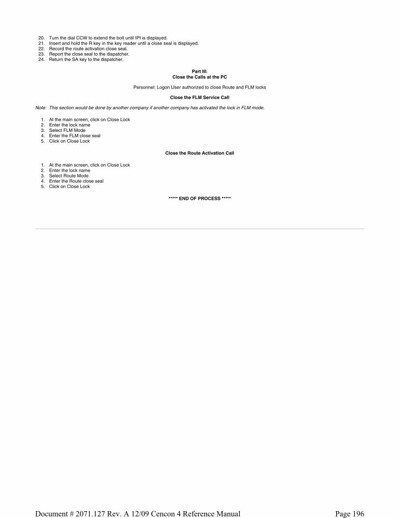
20. Turn the dial CCW to extend the bolt until IPI is displayed. 21. Insert and hold the R key in the key reader until a close seal is displayed. 22. Record the route activation close seal. 23. Report the close seal to the dispatcher. 24. Return the SA key to the dispatcher.
Part III: Close the Calls at the PC
Personnel: Logon User authorized to close Route and FLM locks
Close the FLM Service Call
Note: This section would be done by another company if another company has activated the lock in FLM mode.
1. At the main screen, click on Close Lock 2. Enter the lock name 3. Select FLM Mode 4. Enter the FLM close seal 5. Click on Close Lock
Close the Route Activation Call
1. At the main screen, click on Close Lock 2. Enter the lock name 3. Select Route Mode 4. Enter the Route close seal 5. Click on Close Lock
***** END OF PROCESS *****
Page 196Document # 2071.127 Rev. A 12/09 Cencon 4 Reference Manual
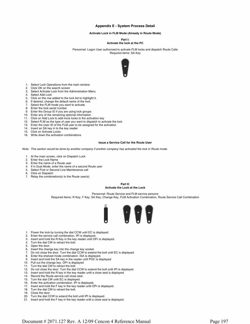
Appendix E - System Process Detail
Activate Lock in FLM Mode (Already in Route Mode)
Part I: Activate the lock at the PC
Personnel: Logon User authorized to activate FLM locks and dispatch Route Calls Required items: SA Key
1. Select Lock Operations from the main window 2. Click OK on the search screen 3. Select Activate Lock from the Administration Menu 4. Select Add Lock 5. Click on the row added to the lock list to highlight it. 6. If desired, change the default name of the lock 7. Select the FLM mode you want to activate 8. Enter the lock serial number 9. Enter the Group ID if you are using lock groups
10. Enter any of the remaining optional information 11. Click on Add Lock to add more locks to the activation key 12. Select FLM as the type of user you want to dispatch to activate the lock 13. Enter the User ID of the FLM user to be assigned for the activation 14. Insert an SA key in to the key reader 15. Click on Activate Locks 16. Write down the activation combinations
Issue a Service Call for the Route User
Note: This section would be done by another company if another company has activated the lock in Route mode.
1. At the main screen, click on Dispatch Lock 2. Enter the Lock Name 3. Enter the name of a Route user 4. If in Dual Mode, enter the name of a second Route user 5. Select First or Second Line Maintenance call 6. Click on Dispatch 7. Relay the combination(s) to the Route user(s)
Part II: Activate the Lock at the Lock
Personnel: Route Service and FLM service persons Required Items: R Key, F Key, SA Key, Change Key, FLM Activation Combination, Route Service Call Combination
1. Power the lock by turning the dial CCW until EC is displayed 2. Enter the service call combination. IPI is displayed. 3. Insert and hold the R Key in the key reader until OPr is displayed. 4. Turn the dial CW to retract the bolt. 5. Open the door. 6. Insert the change key into the change key socket. 7. Do not close the door. Turn the dial CCW to extend the bolt until EC is displayed 8. Enter the shelved mode combination. ISA is displayed. 9. Insert and hold the SA key in the reader until POC is displayed
10. Pull out the change key. OPr is displayed 11. Turn the dial CW to retract the bolt. 12. Do not close the door. Turn the dial CCW to extend the bolt until IPI is displayed 13. Insert and hold the R key in the key reader until a close seal is displayed. 14. Record the Route service call close seal. 15. Turn the dial CW until EC is displayed. 16. Enter the activation combination. IPI is displayed. 17. Insert and hold the F key in the key reader until OPr is displayed. 18. Turn the dial CW to retract the bolt. 19. Close the door. 20. Turn the dial CCW to extend the bolt until IPI is displayed. 21. Insert and hold the F key in the key reader until a close seal is displayed.
Page 197Document # 2071.127 Rev. A 12/09 Cencon 4 Reference Manual

22. Record the FLM activation close seal. 23. Report the close seal to the dispatcher. 24. Return the SA key to the dispatcher.
Part III: Close the Calls at the PC
Personnel: Logon User authorized to close Route and FLM locks
Close the FLM Activation Call
1. At the main screen, click on Close Lock 2. Enter the lock name 3. Select FLM Mode 4. Enter the FLM close seal 5. Click on Close Lock
Close the Route Service Call
Note: This section would be done by another company if another company has activated the lock in Route mode.
1. At the main screen, click on Close Lock 2. Enter the lock name 3. Select Route Mode 4. Enter the Route close seal 5. Click on Close Lock
***** END OF PROCESS *****
Page 198Document # 2071.127 Rev. A 12/09 Cencon 4 Reference Manual

Appendix E - System Process Detail
FLM or Route Service Call
Part I: Issue Service Call Combination
Personnel: Logon User authorized to issue FLM/Route Service Calls
Issue Service Call Combination for FLM
1. At the main screen, click on dispatch lock 2. Enter a lock name 3. Select FLM Mode 4. Enter the name of an FLM user 5. If in dual mode, enter the name of a second FLM 6. Select 2nd Line Maintenance call if you want to disable the lock open alarm for this service call. 7. Click on dispatch 8. Relay combination(s) to FLM(s)
- OR -
Issue Service Call Combination for Route Person
1. At the main screen, click on dispatch lock 2. Enter a lock name 3. Select Route Mode 4. Enter the name of a Route user 5. If in dual mode, enter the name of a second Route user 6. Select 2nd Line Maintenance call if you want to disable the lock open alarm for this service call. 7. Click on dispatch 8. Relay combination(s) to Route User(s)
PART II: Complete Service Call at the Lock
Personnel: FLM or Route Person Required Items: R or F KEY, Service combination
OR
1. Power lock by turning dial CCW until EC is displayed 2. Enter the service call combination.IPI is displayed. 3. Insert and hold F or R key in the key reader until OPr is displayed. 4. Turn the dial CW to retract the bolt. 5. Open the door. 6. Perform service operations. 7. Close door. 8. Turn the dial CCW to extend the bolt until IPI is displayed. 9. Insert and hold the F or R key in the key reader until a close seal is displayed.
10. Record the close seal. 11. Report the close seal to the dispatcher.
Part III: Close the Service Call at the PC
Personnel: Logon User authorized to close Route/FLM locks
Close the FLM Service Call
1. At the main screen, click on Close Lock 2. Enter the lock name 3. Select FLM Mode 4. Enter the FLM close seal 5. Click on Close Lock
- Or -
Close the Route Service Call
1. At the main screen, click on Close Lock 2. Enter the lock name 3. Select Route Mode 4. Enter the Route close seal
Page 199Document # 2071.127 Rev. A 12/09 Cencon 4 Reference Manual

5. Click on Close Lock
***** END OF PROCESS *****
Page 200Document # 2071.127 Rev. A 12/09 Cencon 4 Reference Manual

Appendix E - System Process Detail
Pre-defined Routes
Part I: Issue Route Combinations
Personnel: Logon User authorized to issue Routes
1. At the main screen, click on Route Report 2. In the Route Report, select a route and click on route lock listing. 3. Select/Enter RSP names if not already entered. 4. Click on dispatch. 5. Give the combinations to the RSP(s).
Part II: Use combinations on Route
Personnel: Route Person
Required Items: R Key, Route Combinations
1. Power lock by turning dial CCW until EC is displayed 2. Enter the route call combination.IPI is displayed. 3. Insert and hold F or R key in the key reader until OPr is displayed. 4. Turn the dial CW to retract the bolt. 5. Open the door. 6. Perform service operations. 7. Close door. 8. Turn the dial CCW to extend the bolt until IPI is displayed. 9. Insert and hold the F or R key in the key reader until a close seal is displayed.
10. Record the close seal. 11. Report the close seal to the dispatcher or turn in the key when the route is completed.
Note
Repeat the above process for each lock visit identified in the route.
Part III: Close Route at the PC
Personnel: Logon User authorized to close Route locks
Note
Each route lock visit can be closed as completed or the entire route can be closed with the key once the route is completed.
Close Route Visit Using Menu
1. At the main screen, click on Route Report 2. In the Route Report, select a route and click on Route Lock Listing. 3. Enter the close seal for each lock visited on the route. 4. Click on Close Route with Menu.
- OR -
Close Route Using Key
1. At the main screen, click on Route Report 2. In the Route Report, select a route and click on Route Lock Listing. 3. Insert the Route key containing the route close seals 4. Click on Close with Key
***** END OF PROCESS *****
Page 201Document # 2071.127 Rev. A 12/09 Cencon 4 Reference Manual

Appendix E - System Process Detail
Retrieve and Report on Audit Download
Part I: Retrieve Audit From Lock
Personnel: FLM or Route Person Required Items: SA Key
1. Power lock by turning dial CCW until EC is displayed 2. Press #0 on the lock keypad. -dL is displayed. Dial Left until ISA is displayed. 3. Insert and hold the SA key in the reader while AUD is displayed. 4. Continue to hold the SA key in the reader and turn dial as necessary until EOP is displayed. 5. Return the SA key to the dispatcher for reporting.
Part II: Report on Audit Download
Personnel: Logon user authorized to access key report Required Items: SA Key
1. Insert an SA key containing an Audit download in the key reader. 2. From the main screen, select Key Report.
***** END OF PROCESS *****
Page 202Document # 2071.127 Rev. A 12/09 Cencon 4 Reference Manual

Appendix E - System Process Detail
Shelve Lock
Part I: Shelve Lock at the PC
Personnel: Logon user authorized to shelve locks Required Items: SA Key
1. IN the main screen, click on lock operations. 2. Click OK on the search screen. 3. In the Lock Operations Report, select the locks to be shelved. 4. Select Shelve Locks from the Administration Menu. 5. Assign users to perform the shelve. 6. Insert an SA key into the key reader. 7. Click on 8. Write Shelve Lock Key. 9. Write down the shelve combination.
Part II: Shelve Lock at Lock
Personnel: FLM OR Route service person Required Items: F or R key, SA key, change key, shelve combination
1. Power lock by turning dial CCW until EC is displayed. 2. Enter the shelving combination. IPI is displayed. 3. Insert and hold F or R key in the reader until OPr is displayed. 4. Turn the dial CW to retract bolt. 5. Open the door. 6. Insert a change key in the socket.
7. DO NOT CLOSE DOOR. Turn the dial CCW to extend the bolt until is displayed. 8. Enter the factory mode combination. ISA is displayed. 9. Insert and hold the SA key in the key reader until POC is displayed.
10. Pull out the change key. OPR is displayed. 11. Turn the dial CW to retract the bolt. 12. Close the door. 13. Turn the dial CCW to extend the bolt until IPI is displayed. 14. Insert and hold F or R key in the key reader until a close seal is displayed. 15. Record the close seal. 16. Report the close seal to the dispatcher. 17. Return the SA key to the dispatcher to verify shelving..
Part III: Close the Service Call
Personnel: Logon user authorized to close locks
Close FLM Service Call
1. At the main screen, click on Close Lock. 2. Enter the lock name and close seal. 3. Select FLM mode. 4. Click on Close Lock.
- OR -
Close Route Service Call
1. At the main screen, click on Close Lock. 2. Enter the lock name and close seal. 3. Select Route mode. 4. Click on Close Lock.
Page 203Document # 2071.127 Rev. A 12/09 Cencon 4 Reference Manual

Part IV: Shelve Verification
Personnel: Logon user authorized to shelve locks
1. In the main screen, click on lock operations. 2. Click OK on the Search screen. 3. Place the SA key in the reader. 4. Select Verify Shelve Locks from the Administration Menu.
**** END OF PROCESS *****
Page 204Document # 2071.127 Rev. A 12/09 Cencon 4 Reference Manual

Appendix E - System Process Detail
Add Bank Users to Lock after Activation
Part I: Add users to the lock using Cencon
Personnel: Logon user authorized to add bank users
1. Insert an SA key into the key reader 2. Open a lock report and select the desired bank lock 3. From the Administration Menu, select "Add Users to a Bank Mode Lock" 4. Select users from the Available Users list and press OK 5. The SA key is initialized with the user information
Part II: Add users to the lock at the lock
Personnel: Bank supervisor
Required items: B key, SA key, change key, user's combination
1. Power Lock → EC Turn the dial to the left (CCW) until EC (Enter Combination) is displayed.
2. EC → Enter combination → IPI If operating a Cencon Vertical lock, position the lip of the dial to cover the red bar. When EC is displayed, key in the Bank User's combination. IPI (Insert Personal Identifier) will be displayed.
3. IPI → Insert Personal Identifier Key → OPr Insert the User's Personal Identifier B Key into the key reader. OPr (Open right) will be displayed.
4. OPr → Retract bolt and Open the Door Turn the Dial to the right (CW) to open the lock.
5. Insert change key and Extend the Bolt Insert the change key into the change key socket. Extend bolt but do not close door.
6. Power Lock → EC Turn the dial to the left (CCW) until EC (Enter Combination) is displayed.
7. EC → Enter Default Combination → ISA If operating a Cencon Vertical lock, position the lip of the dial to cover the red bar. When EC is displayed, Enter the default factory combination of 50-25-50. ISA, (Insert Supervisor Audit Key) will be displayed.
8. ISA → Insert and Hold SA Key → Add Insert and hold the SA key in the key reader on the side of the lock. The lock will display Add (Adding Users) while the information is being processed.
9. Add → POC Continue to hold the SA Key in the reader until POC (Pull Out Change Key) is displayed.
10. POC → Remove SA Key and Pull Out Change Key → OPr Remove the SA key and the change Key. OPr (OPen right) will be displayed.
11. OPr → Retract Bolt and Close the Door Turn the dial to the right (CW) to retract the bolt. Adding Users is now complete for the Users that were programmed into the SA key. Close the door.
12. Extend Bolt → IPI Extend the bolt by turning the dial to the left (CCW). IPI (Insert Personal Identifier) will be displayed.
13. IPI → Insert Personal Identifier Key → EOP Insert the User's Personal Identifier B Key into the key reader again. The lock will confirm the closure by writing the date and time of the close into the B key and displaying EOP (End of Operation).
Note
After adding a User you may need to change the combinations for the User that was added. For Gen1 locks, Bank User combinations are initially set to the default combination of 50-25-50 and will not open the lock until changed to a valid new combination. However, with Gen2 locks, it is possible to have a unique combination set to a bank user from the software, and optionally force the user to change the combination or allow the user to open the lock with this combination.
Page 205Document # 2071.127 Rev. A 12/09 Cencon 4 Reference Manual
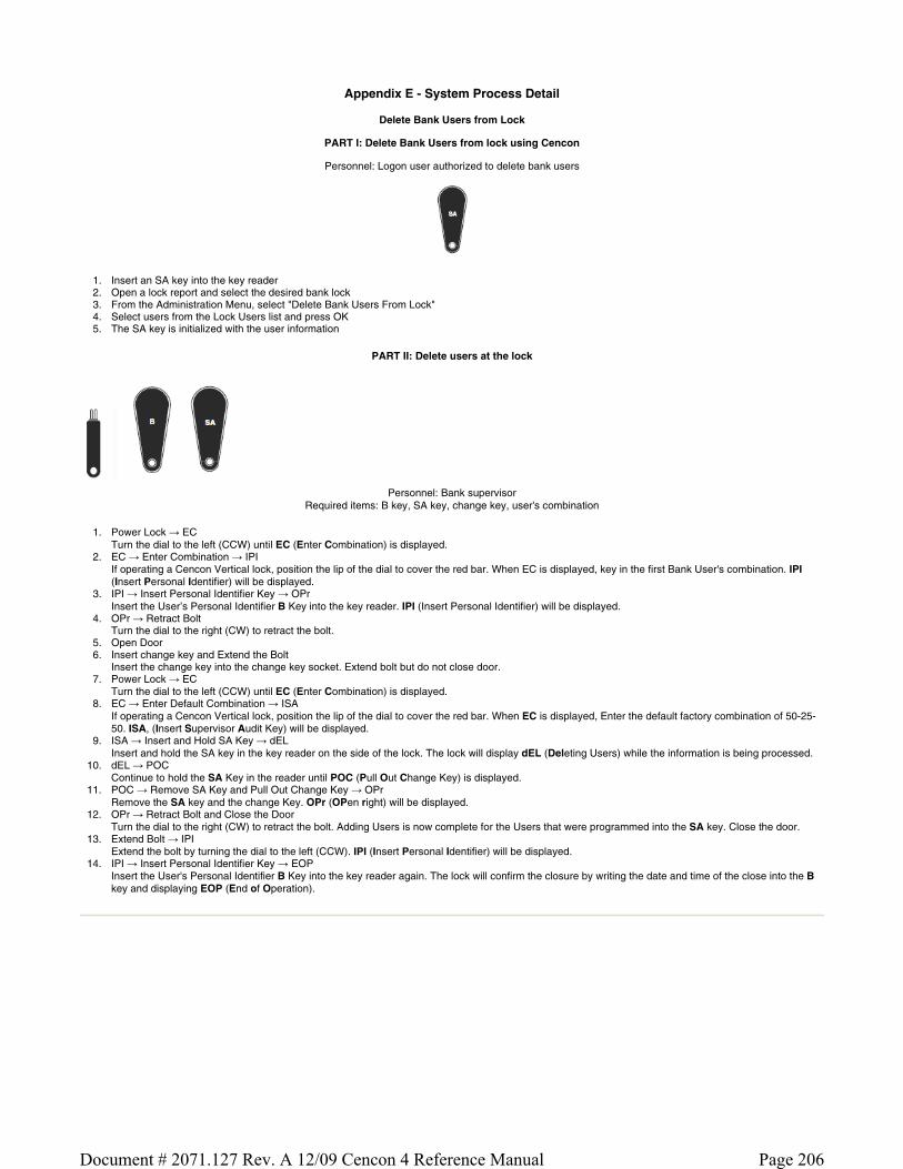
Appendix E - System Process Detail
Delete Bank Users from Lock
PART I: Delete Bank Users from lock using Cencon
Personnel: Logon user authorized to delete bank users
1. Insert an SA key into the key reader 2. Open a lock report and select the desired bank lock 3. From the Administration Menu, select "Delete Bank Users From Lock" 4. Select users from the Lock Users list and press OK 5. The SA key is initialized with the user information
PART II: Delete users at the lock
Personnel: Bank supervisor Required items: B key, SA key, change key, user's combination
1. Power Lock → EC Turn the dial to the left (CCW) until EC (Enter Combination) is displayed.
2. EC → Enter Combination → IPI If operating a Cencon Vertical lock, position the lip of the dial to cover the red bar. When EC is displayed, key in the first Bank User's combination. IPI (Insert Personal Identifier) will be displayed.
3. IPI → Insert Personal Identifier Key → OPr Insert the User’s Personal Identifier B Key into the key reader. IPI (Insert Personal Identifier) will be displayed.
4. OPr → Retract Bolt Turn the dial to the right (CW) to retract the bolt.
5. Open Door 6. Insert change key and Extend the Bolt
Insert the change key into the change key socket. Extend bolt but do not close door. 7. Power Lock → EC
Turn the dial to the left (CCW) until EC (Enter Combination) is displayed. 8. EC → Enter Default Combination → ISA
If operating a Cencon Vertical lock, position the lip of the dial to cover the red bar. When EC is displayed, Enter the default factory combination of 50-25-50. ISA, (Insert Supervisor Audit Key) will be displayed.
9. ISA → Insert and Hold SA Key → dEL Insert and hold the SA key in the key reader on the side of the lock. The lock will display dEL (Deleting Users) while the information is being processed.
10. dEL → POC Continue to hold the SA Key in the reader until POC (Pull Out Change Key) is displayed.
11. POC → Remove SA Key and Pull Out Change Key → OPr Remove the SA key and the change Key. OPr (OPen right) will be displayed.
12. OPr → Retract Bolt and Close the Door Turn the dial to the right (CW) to retract the bolt. Adding Users is now complete for the Users that were programmed into the SA key. Close the door.
13. Extend Bolt → IPI Extend the bolt by turning the dial to the left (CCW). IPI (Insert Personal Identifier) will be displayed.
14. IPI → Insert Personal Identifier Key → EOP Insert the User's Personal Identifier B Key into the key reader again. The lock will confirm the closure by writing the date and time of the close into the B key and displaying EOP (End of Operation).
Page 206Document # 2071.127 Rev. A 12/09 Cencon 4 Reference Manual

Appendix F - Determine Lock Level
It is sometimes necessary to determine the level of the Cencon Lock with which you are working. This can be done by entering a command via the keypad. The lock level will then be displayed on the LCD. Use the following procedure:
1. Power the lock by turning the dial to the left (counter clock wise) until EC is displayed. 2. Enter the # 1 keypad command.
Output from a Gen2 lock:
The lock displays a string of characters on the LCD, displaying three characters at a time.
The lock code and hardware levels are displayed in a easily readable manner (for example, “LL-“, “G 2”, “002”, “000”, “000”, “789”, “HL-“, “ 01”, “ 01” where Gen 2 firmware version 2.000.000789 is indicated.)
Output from a Gen1 lock:
The lock displays a string of characters on the LCD, displaying two characters at a time.
Example
LL 4C 38 54 35 39 42 HL 00 02 The LL displayed in the character string stands for Lock Level while the HL stands for Hardware Level. The numbers following the LL indicator are the hexadecimal representations of the ASCII codes for numbers and letters as we know them. These numbers and letters can be decoded using the following table. Each pair of characters represents 1 letter or number. For instance "4C" represents the letter "L" in our alphabet.
The numbers following the HL indicator do not have to be decoded. It is simply a numerical representation as we know it.
The length of the display string will vary depending on which lock model you have. The best thing to do in analyzing the lock level is to write down the entire string and then pick out the portions of it that are significant to you, or if you are experiencing a problem with the lock, report the entire string to the Tech Support group.
The Lock Level string will consist of either 6 or 7 pair of characters and the Hardware Level will consist of 2 pair of characters. When decoded, the Lock Level will be either a 6 or 7 character representation and the Hardware Level will be 2 characters.
The most relevant characters when analyzing the string displayed are the last three sets of characters displayed before the letters HL. In the previous example, the three sets of characters are "35 39 42". These are decoded to indicate the Lock Code Level and Version is 59B.
Example
LL 4C 38 54 36 36 42 HL 00 02
This indicates a Lock Code Level of 66, Version B.
Hexadecimal Decode Table
Hex Number
DecodedNumber
Hex Number
DecodedNumber
Hex Number
DecodedNumber
30 0 41 A 4E N
31 1 42 B 4F O
32 2 43 C 50 P
33 3 44 D 51 Q
34 4 45 E 52 R
35 5 46 F 53 S
36 6 47 G 54 T
37 7 48 H 55 U
38 8 49 I 56 V
39 9 4A J 57 W
4B K 58 X
4C L 59 Y
4D M 5A Z
Page 207Document # 2071.127 Rev. A 12/09 Cencon 4 Reference Manual

Glossary
Activity Log Table This is the database table used to store a history of activity and operations for the Cencon System. See section 3.4.1 List Activity Log.
Archive Activity Log Table This is the database table used to store a older records from the Activity Log Table. See section 3.4.2 Archived Activity Log.
Archive User ID History Log Table This is the database table used to store older records from the User ID History Log Table in case that table becomes very large. See section 3.4.7 Archived User History Log.
Bank Branch ID A four digit code that identifies the Bank Branch that manages the locks being controlled by this system.
Bank Mode An operating mode normally used by Bank employees. The lock will open using Repeating Access Code(s) + the Bank key(s), and close seals are not used.
CCW Counterclockwise rotation to the left. This is used in referring to the direction that the lock dial should be turned at certain times when performing lock operations.
Change Key A two pronged, non programmable, key that is inserted into the back of the lock for activating and shelving locks, changing the shelved-mode combination, and adding and deleting Bank mode users.
Company ID The value entered for this field can be any four-digit number you wish to identify your company. You should choose a number that is, in some way, meaningful to your company. Once this ID is set, you cannot change it. If you are a branch of a larger company, you must enter the Company ID that has already been chosen for your company. If you are planning to activate locks from a remote PC, the Company ID must be the same on all systems involved in the process.
Customer ID The Customer ID is value used to associate a customer with locks or a route. Information on customers is stored in the Customer Table. This is especially useful when a single company is servicing locks for multiple customers. See section 3.3 Customers.
CW Clockwise rotation to the right. This is used in referring to the direction that the lock dial should be turned at certain times when performing lock operations, such as retracting the bolt when "OPr" displays. You can also dial clockwise to bypass the change key symbol in order to open the lock when the change key was accidentally left inserted and the door was shut.
Dispatcher The dispatcher is the person who works directly with the Cencon computer system to direct the operations of the First Line Maintenance and Route Personnel. As a part of this process, the dispatcher uses the computer system to generate lock combinations for issue to First Line Maintenance and Route Personnel so that they may access the locks at the ATM's that they are servicing or replenishing. See section 3.6 Define Function Authorization Levels.
D Key The black Dispatcher Personal Identifier Key that is used by the Dispatchers to allow access to the certain functions in the Cencon program.
Dual User Access Mode A setting in the lock activation process that causes the lock to require two users to open the lock.
Electronic Key This is the key reader that is attached to the PC as a peripheral item. It is used to write and read data to and from, respectively, the Smart Keys.
F Key The blue FLM Personal Identifier Key that is programmed at the PC to authorize an FLM to open locks using the supplied One Time Combination.
First Line Maintenance ( FLM ) Personnel Those personnel who will be accessing ATM's on a call by call basis. An FLM person is typically set up to only have one lock combination issued at a time.
Fob A metal or plastic molding into which an electronic chip can be imbedded to form a Smart Key.
GMT The acronym for Greenwich Mean Time. This is the zero line for all time zones. Each time zone is offset from the zero line by a specific number of hours. The number of hours to be used for offset correlates to the number of time zones that you are away from the zero line. With the induction of daylight savings time, this offset decreases by one hour. (See also UTC.)
Group I.D. A six character identification for a group of locks. This feature allows an Lock to be assigned to a group that may only be serviced by FLMs and RSPs who are assigned to service that group.
iButton The trademarked Dallas Semiconductor name for the electronic keys used with the Cencon System.
Lock Table This is the database table used to store the locks defined in the Cencon system. See section 3.1.1 List Locks.
Page 208Document # 2071.127 Rev. A 12/09 Cencon 4 Reference Manual
Lock Log Archive Table
This is the database table used to store older records from the Lock Log History table. This is used to reduce the size of the Lock Log History Table when it becomes very large. See section 3.4.3 Lock Log History, and section 3.4.4 Archived Lock Log History.
Lock Log History Table This is the database table used to store a history of dispatches to locks in the Cencon system. See section 3.4.3 Lock Log History.
One Time Combination (OTC) A unique combination that will allow a lock to opened one time by an authorized user with the correct Smart Key.
Open Lock Log Table This is the database table used to store a log of the currently open locks in the Cencon system. See section 3.4.1 List Open Locks.
PowerStarTM technology The technology that allows the Cencon lock to operate using internally generated power. No batteries or external power are required.
R Key The yellow Route Personal Identifier Key that is programmed at the PC to authorize a Route user to open locks using the supplied One Time Combination.
Region
Region control is a method of controlling which locks and Lock Users can be viewed and managed by different Cencon Logon Users.
Route This is a series of route locks that have been dispatched as a group. This is generally used to allow Route Service Personnel to get the combinations for all the locks on a route prior to leaving. See section 3.1.3 Route Report.
Route Table This is the database table used by the Cencon system to store a record of the different defined routes. This table defines what routes have been created. See section 3.1.3 Route Report.
Route Lock Table This is the database table used by the Cencon system to store what locks are on each route. See section 3.1.3.1 Route Lock Listing Report.
Route Service Personnel (RSP) Those personnel who will be accessing specified ATM's on a given route, usually to replenish currency. They can have combinations issued for multiple locks at one time. Route personnel can also be dispatched by the Dispatcher on a one time basis to perform service at an Lock.
Shelved Mode This is the default mode of a Cencon lock when it is shipped from the factory. It is also the mode that a Cencon lock is put in when it is not actively being used; i.e., "shelved from service".
S Key The black Supervisor Personal Identifier Key that is used by the Supervisor to access the certain menus of the Cencon program.
SA Key The red Supervisor Audit key which is initialized at the PC with information needed to activate or shelve locks. It is also used to retrieve audit records, Add and Delete Bank mode users, download a Bank Mode User Table, etc.
Single User Access Mode A setting in the lock activation process that causes the lock to require only one user to open the lock.
Smart Key This is a Dallas Semiconductor electronic chip imbedded in a fob.
Smart Key Reader This is the key reader that is attached to the PC as a peripheral item. It is used to write and read data to and from, respectively, the Smart Keys.
Special Supervisor A type of Cencon logon key, that allows access to special supervisor level functions. This is the highest level of authorization for a Cencon logon key. This is controlled by the authorizations defined for access to different functions. See section 3.6 Define Function Authorization Levels.
SS Key The black Special Supervisor Personal Identifier Key that is used by the Special Supervisor to access all menus in the Cencon program.
Supervisor A type of Cencon logon key, that allows access to supervisor level functions. This is controlled by the authorizations defined for access to different functions. See section 3.6 User Authorization.
Two Person Integrity ( TPI ) When a lock is activated in FLM, Route, or Bank mode with the Dual Access requirement, two individuals, each with their own combination and their own Smart Key, would be required to open the lock.
User ID Table This is the database table used to store the users defined for the Cencon system. This contains information for FLM and RSP keys for access to locks, as well as information on Dispatcher, Supervisor, and Special Supervisor keys for logging onto Cencon.
User ID History Log Table This is the database table used to store information on previous users assigned to keys for the Cencon system. This table is used to look up information on users from lock audit reports where that user may have been deleted from the system, or the key user ID may have been renamed for assignment to another user.
Page 209Document # 2071.127 Rev. A 12/09 Cencon 4 Reference Manual

UTC
An abbreviation for Coordinated Universal Time. This is the zero line for all time zones. Each time zone is offset from the zero line by a specific number of hours. The number of hours to be used for offset correlates to the number of time zones that you are away from the zero line. With the induction of daylight savings time, this offset decreases by one hour. Also known as "GMT" (Greenwich Mean Time.)
Page 210Document # 2071.127 Rev. A 12/09 Cencon 4 Reference Manual