Power converters -...
78
Frédérick BORDRY CERN Introduction to Accelerator Physics 2009 Special CAS@CERN 23 rd – 27 th February 2009 Divonne Power converters Definitions and classifications Converter topologies
Transcript of Power converters -...

Frédérick BORDRY
CERN
Introduction to Accelerator Physics 2009
Special CAS@CERN
23rd – 27th February 2009
Divonne
Power convertersDefinitions and classifications
Converter topologies
Fk.
Bo
rdry
Pow
er C
onver
ters
Spec
ial
CA
S-C
ER
N D
ivonne
27 F
ebru
ary 2
009
2
Menu
- Power converter definition and classification
- Power converter topologies: commutationSources, switches,…semiconductors
- Special case for magnet powering (Voltage source - Current source)
- Pulsed power converters
- Control and precision
In 1 hour ????

Fk.
Bo
rdry
Pow
er C
onver
ters
Spec
ial
CA
S-C
ER
N D
ivonne
27 F
ebru
ary 2
009
3
The source of the beam blow-up when we could not
prove it was the RF (Control room operator)
A powerful (small) black box able to convert MAD files
into currents (Accelerator Physics group member)
An equipment with three states, ON, OFF and FAULT
(Another operator)
Is it the same thing as a power supply?
(Person from another physics lab)
A big box with wires and pipes everywhere and
blinking lamps. Occasionally it goes BANGG!
(Former PO secretary view)
Power converters : Definitions

Fk.
Bo
rdry
Pow
er C
onver
ters
Spec
ial
CA
S-C
ER
N D
ivonne
27 F
ebru
ary 2
009
4
That which feeds the magnets (a visitor)
A stupid installation taking a non-sinusoidal current
at poor power factor (Power distribution engineer)
A standard piece of equipment available from
industry off-the-shelf
(a higher management person, not in in this room !)
Power converters : Definitions (cont’d)

Fk.
Bo
rdry
Pow
er C
onver
ters
Spec
ial
CA
S-C
ER
N D
ivonne
27 F
ebru
ary 2
009
5
The task of a power
converter is to process
and control the flow of
electric energy by
supplying voltages and
currents in a form that
is optimally suited for
user loads.
50 or 60 Hz ; AC
Control
Industrial applications,
Welding, Induction Heating, ….
Domestic Appliance
Traction
and auxiliary
Medical applications
DC current
Energy source Applications

Fk.
Bo
rdry
Pow
er C
onver
ters
Spec
ial
CA
S-C
ER
N D
ivonne
27 F
ebru
ary 2
009
6
Schematic of Cockcroft and Walton’s voltage
multiplier. Opening and closing the switches S
transfers charge from capacitor K3 through
the capacitors X up to K1.
Voltage multiplier : switches…
High energy physics and power converters

Fk.
Bo
rdry
Pow
er C
onver
ters
Spec
ial
CA
S-C
ER
N D
ivonne
27 F
ebru
ary 2
009
7
The difficulties of maintaining high voltages led
several physicists to propose accelerating
particles by using a lower voltage more than
once. Lawrence learned of one such scheme in
the spring of 1929, while browsing through an
issue of Archiv für Elektrotechnik, a German
journal for electrical engineers. Lawrence read
German only with great difficulty, but he was
rewarded for his diligence: he found an article by
a Norwegian engineer, Rolf Wideröe, the title of
which he could translate as “On a new principle
for the production of higher voltages.” The
diagrams explained the principle and Lawrence
skipped the text.
“On a new principle for the production of higher voltages.”

Fk.
Bo
rdry
Pow
er C
onver
ters
Spec
ial
CA
S-C
ER
N D
ivonne
27 F
ebru
ary 2
009
8
Once upon a time…. not so far
This is a 6-phase device,
150A rating with grid
control.
It measures 600mm high
by 530mm diameter.

Fk.
Bo
rdry
Pow
er C
onver
ters
Spec
ial
CA
S-C
ER
N D
ivonne
27 F
ebru
ary 2
009
9
une commutatrice des tramways de Saint-Etienne, datant de 1907 et
ayant fonctionné jusqu'en avril 1991
In the beginning… for high power

Fk.
Bo
rdry
Pow
er C
onver
ters
Spec
ial
CA
S-C
ER
N D
ivonne
27 F
ebru
ary 2
009
10
and still now in “old” accelerators…
Brookhaven National Laboratory - AGS
CERN - PS
By courtesy: I. Marneris

Fk.
Bo
rdry
Pow
er C
onver
ters
Spec
ial
CA
S-C
ER
N D
ivonne
27 F
ebru
ary 2
009
11
In general, accelerator designers are not power converter experts and
vice versa.
Interface is the list of power converter specifications.
The apparent belief on one side that anything is possible and the
impression on the other side that the specification have been
chosen at random, sometimes leads to rather cynical feelingssuch as:
-if in doubt, ask an extra order of magnitude, there is never a problem or whatever it is,
or
- however it is calculated, 1 in 103 will be good enough in the end and they’ll never
note the ripple and the zero crossing !!!
Power converters specifications
"Do you have one or two power converters for the test of magnet
prototypes? 200 A will be enough ?
Precision is not important for time being.
Don’t worry it’s not urgent. Next month is OK "
(Email received 05.12.08)
Fk.
Bo
rdry
Pow
er C
onver
ters
Spec
ial
CA
S-C
ER
N D
ivonne
27 F
ebru
ary 2
009
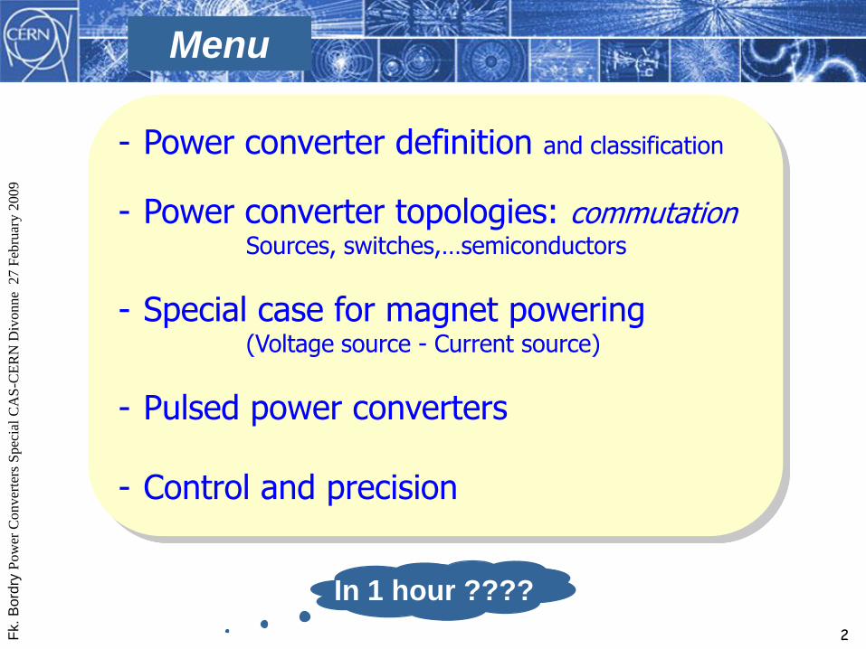
12
Power Converter
Design
- performance- efficiency
- reliability (MTBF), reparability (MTTR),
- effect on environment (RFI, noise,...)
- low cost
Power Converter
Source Source
Control
Ii
Vi
Io
Vo
Electrical energy transfer
Topologies
IEC 146 definition
(not supply,not rectifier)

Fk.
Bo
rdry
Pow
er C
onver
ters
Spec
ial
CA
S-C
ER
N D
ivonne
27 F
ebru
ary 2
009
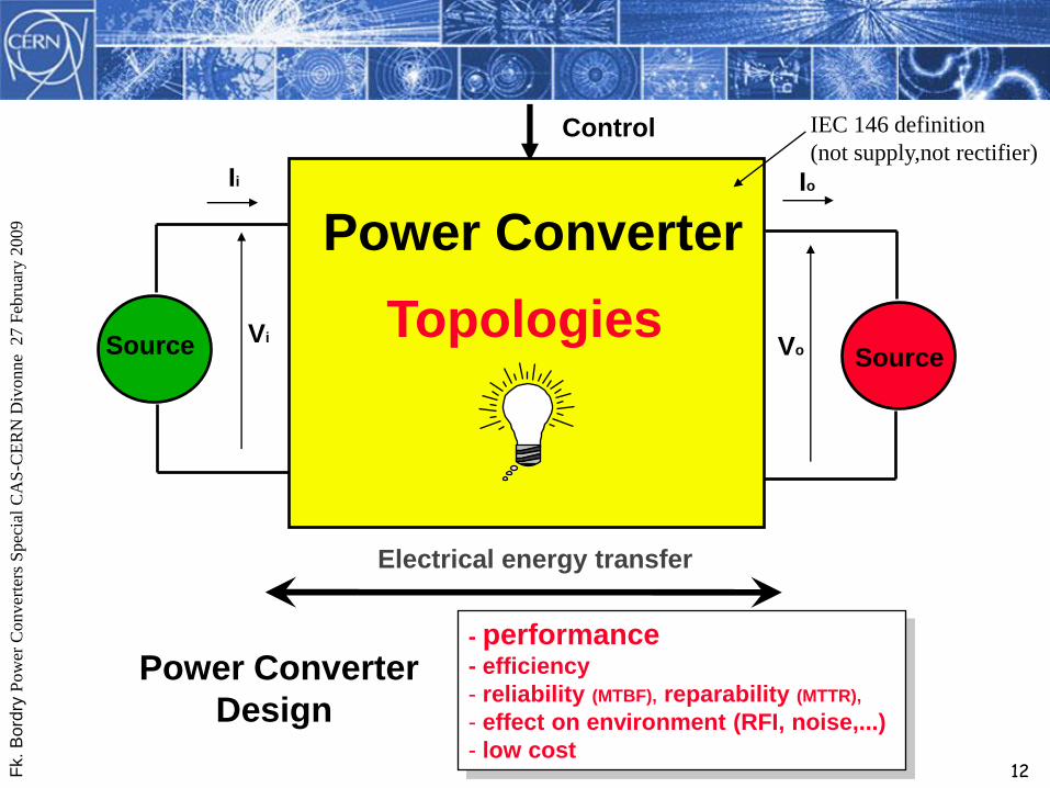
13
DC 1
DC 2
AC 1
AC 2
Inverter
Rectifier
Chopper
f1 = f2
frequency direct
converter
(cycloconverter)
f1 = f2
AC controller
(transformer)
Converter classification
Fk.
Bo
rdry
Pow
er C
onver
ters
Spec
ial
CA
S-C
ER
N D
ivonne
27 F
ebru
ary 2
009
14
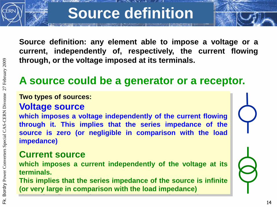
Source definition
Source definition: any element able to impose a voltage or a
current, independently of, respectively, the current flowing
through, or the voltage imposed at its terminals.
A source could be a generator or a receptor.
Two types of sources:
Voltage sourcewhich imposes a voltage independently of the current flowing
through it. This implies that the series impedance of the
source is zero (or negligible in comparison with the load
impedance)
Current sourcewhich imposes a current independently of the voltage at its
terminals.
This implies that the series impedance of the source is infinite
(or very large in comparison with the load impedance)

Fk.
Bo
rdry
Pow
er C
onver
ters
Spec
ial
CA
S-C
ER
N D
ivonne
27 F
ebru
ary 2
009
15
L
C
II state variable
dI/dt ≠ “ Current source “
v
dV/dt ≠
V state variable
“ Voltage source “
Source examples
2L 2
1LIE
2CV2
1
cE

Fk.
Bo
rdry
Pow
er C
onver
ters
Spec
ial
CA
S-C
ER
N D
ivonne
27 F
ebru
ary 2
009
16
Eight types of sources (reversibility)
Unidirectional source
voltage : if the voltage, across its terminal, can’t change sign
current : if the current, flowing through it, can’t reverse
Bidirectional (reversible) source :
voltage : if the voltage, across its terminal, can change sign
current : if the current, flowing through it, can reverse
+
-
+
-
+
-
+
-
+
-
+
-
+
-
+
-
+
-
+
-
+
-
+
-
Fk.
Bo
rdry
Pow
er C
onver
ters
Spec
ial
CA
S-C
ER
N D
ivonne
27 F
ebru
ary 2
009
17
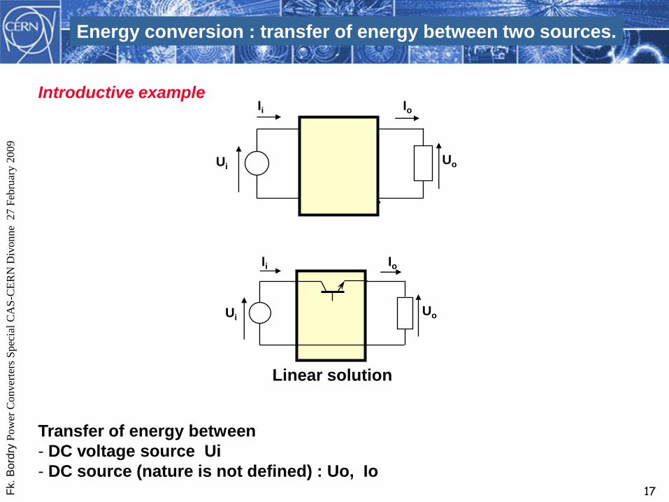
Converter
Ii Io
UoUi
Linear solution
Ii Io
UoUi
Energy conversion : transfer of energy between two sources.
Introductive example
Transfer of energy between
- DC voltage source Ui
- DC source (nature is not defined) : Uo, Io

Fk.
Bo
rdry
Pow
er C
onver
ters
Spec
ial
CA
S-C
ER
N D
ivonne
27 F
ebru
ary 2
009
18
Po = Uo . Io = 10 . 600 = 6’000 W
PT (power dissipated by the switch) = UT. IT = (Ui – Uo) . Io = (24 – 10) . 600 = 8’400 W
Converter efficiency = Po / (PT + Po) = 42 % !!!!!
Furthermore, it’ll be difficult to find a component (semiconductor) able to dissipate 8’400 W .
Then impossible for medium and high power conversion
Linear mode
Ui
Ii Io
Uo
T
Commutation- UT = 0 if IT ≠ 0
- IT = 0 if UT ≠ 0 PT = 0
switch mode
(saturated-blocked)
Linear solution
Ui = 24V ; Uo = 10 V and Io = 600A

Fk.
Bo
rdry
Pow
er C
onver
ters
Spec
ial
CA
S-C
ER
N D
ivonne
27 F
ebru
ary 2
009
19
Ui
Ii Is
Us
Direct Link
Ii Is
Us
Ii Is
Us
Inverse Link Open Link
Active components used as switches to create a
succession of link and no link between sources to
assure an energy transfer between these sources with
high efficiency.
Commutation

Fk.
Bo
rdry
Pow
er C
onver
ters
Spec
ial
CA
S-C
ER
N D
ivonne
27 F
ebru
ary 2
009
20
Direct link configuration : Direct voltage-current converters
U I U I U I
Disconnexion(current source short-circuited,
voltage source open circuited)
Connexion(energy flow between sources)
U
IK1
K2
K4
K3
a b c
- K1 and K3 closed => a
- K2 and K4 closed => b
- K1 and K4 (or K2 and K3) closed => c
U
IK1
K2
K4
K3
U
IK1
K2
K4
K3
U
IK1
K2
K4
K3

Fk.
Bo
rdry
Pow
er C
onver
ters
Spec
ial
CA
S-C
ER
N D
ivonne
27 F
ebru
ary 2
009
21
Ui
Ii Io
Uo
Special case for linear application
Switch-mode converter
Vk1
Vk2
Ik1
Ik2
Linear
conversion
Vk1
Vk2
Ik1
Ik2
- Active filter
- 4-quadrant converters

Fk.
Bo
rdry
Pow
er C
onver
ters
Spec
ial
CA
S-C
ER
N D
ivonne
27 F
ebru
ary 2
009
22
Commutation rules
• electronic switches modify the interconnection of impeding circuits
• any commutation leading instantaneous variations of a statevariable is prohibited
Turn On impossible
V1 V2
Turn Off impossible
I2I1
Interconnection between two impeding networks can be modified only if :
- the two networks are sources of different natures
(voltage and current)
- the commutation is achieved by TWO switches. The states of the
two switches must be different.

Fk.
Bo
rdry
Pow
er C
onver
ters
Spec
ial
CA
S-C
ER
N D
ivonne
27 F
ebru
ary 2
009
23
Power Converter topology design: the problem
the interconnection of sources by switches
Fundamental rules
and
source naturesPower converter topologies
switch characteristics
Vk
Ik
Ik
Vk
Fk.
Bo
rdry
Pow
er C
onver
ters
Spec
ial
CA
S-C
ER
N D
ivonne
27 F
ebru
ary 2
009
24
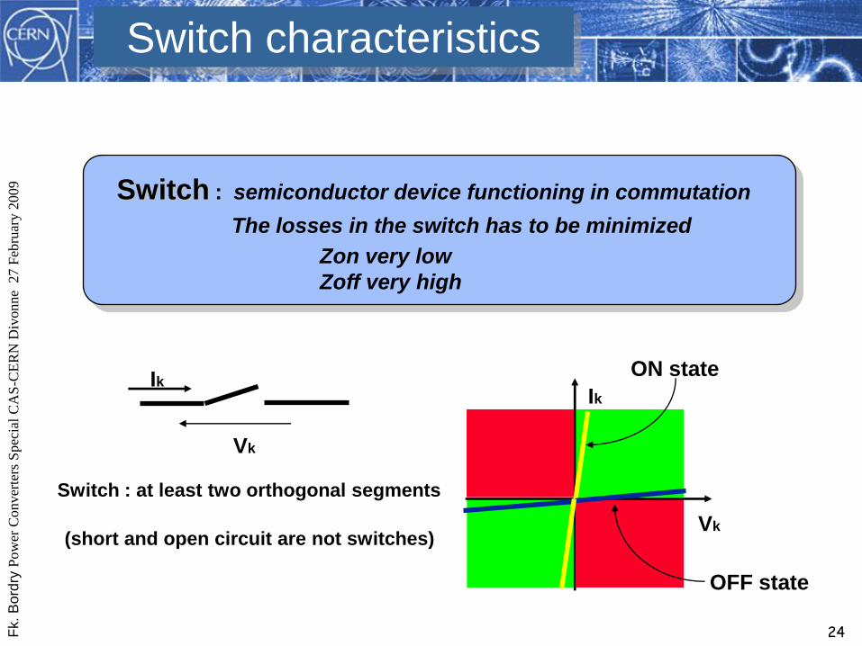
Vk
IkIk
Vk
Switch characteristics
Switch : semiconductor device functioning in commutation
The losses in the switch has to be minimized
Zon very low
Zoff very high
ON state
OFF state
Switch : at least two orthogonal segments
(short and open circuit are not switches)

Fk.
Bo
rdry
Pow
er C
onver
ters
Spec
ial
CA
S-C
ER
N D
ivonne
27 F
ebru
ary 2
009
25
Switches : Dynamic characteristics
ON state OFF state?
• spontaneous commutation
change of quadrant Vk
Ik
(auto turn-on ; auto turn-off)
• controlled commutation
no change of quadrant
(controlled turn-on ; controlled turn-off) Vk
Ik
no switching
losses
Switching
losses
gate

Fk.
Bo
rdry
Pow
er C
onver
ters
Spec
ial
CA
S-C
ER
N D
ivonne
27 F
ebru
ary 2
009
26
Power Semicondutors
Ik
Vk
ONOFF
Ik
Vk
ON
Ik
Vk
Power Semiconductors
Transistors Thyristors
Power Semiconductors
Turn-off DevicesTurn-off Devices Thyristors
Line commutated
Fast
Bi-directional
Pulse
Thyristors
Line commutated
Fast
Bi-directional
Pulse
Diodes
Fast
Line commutated
Avalanche
Diodes
Fast
Line commutated
Avalanche
MOSFETs
Darlingtons
IGBTs
MOSFETs
Darlingtons
IGBTs
GTOs
IGCTs GTOs
IGCTs

Fk.
Bo
rdry
Pow
er C
onver
ters
Spec
ial
CA
S-C
ER
N D
ivonne
27 F
ebru
ary 2
009
27
Power Diode and Thyristor
or SCR (Silicon-Controlled Rectifier )
Link to frequency of the
electrical network
50 Hz (60 Hz)
High frequency => high
performances (ripple,
bandwidth, perturbation
rejection,...)
small magnetic
(volume, weight)
From mercury arc rectifier,
grid-controlled vacuum-tube
rectifier, inignitron ,….
High frequency power semiconductors :
MosFet, IGBTs , GTOs, MCTs,….
Evolution of Power semiconductors
Power Electronics

Fk.
Bo
rdry
Pow
er C
onver
ters
Spec
ial
CA
S-C
ER
N D
ivonne
27 F
ebru
ary 2
009
28
Power Converter
Gene
ratorLoad
Control
IG
VG
IL
VL
Electrical energy transfer
Power Converter for magnets
- low mains harmonic distortion
- power factor (closest to 1)
- low ripple (current)
- reproducibility (short and long term)
- rejection of mains disturbance
- dynamic response
Achieving high performance : COMPROMISE

Fk.
Bo
rdry
Pow
er C
onver
ters
Spec
ial
CA
S-C
ER
N D
ivonne
27 F
ebru
ary 2
009
29
Control
Voltage sourceVoltage source Current sourceCurrent source
Power Converter
Load
IG
VG
IL
VLACDC3 phase mains
(50 or 60 Hz) magnet, solenoid,…
Topologies

Fk.
Bo
rdry
Pow
er C
onver
ters
Spec
ial
CA
S-C
ER
N D
ivonne
27 F
ebru
ary 2
009
30
+ -
+ -
+ -
+
+
-
-
1 Quadrant mode
2 Quadrants mode
4 Quadrants mode
Operating Modes
V
V
V
I
I
I
I
V
1
23
4
Output
Source

Fk.
Bo
rdry
Pow
er C
onver
ters
Spec
ial
CA
S-C
ER
N D
ivonne
27 F
ebru
ary 2
009
31
General power converter topologies
Rectifier1
F
i
l
t
e
r
s

Fk.
Bo
rdry
Pow
er C
onver
ters
Spec
ial
CA
S-C
ER
N D
ivonne
27 F
ebru
ary 2
009
32
Direct Converters : Rectifiers
AC
VoltageDC
Current
F
i
l
t
e
r
sVk
Ik
“ Thyristors “
+
+
-
-

Fk.
Bo
rdry
Pow
er C
onver
ters
Spec
ial
CA
S-C
ER
N D
ivonne
27 F
ebru
ary 2
009
33
Main power converters
12 x [6kA, 2 kV]
SPS Main power converters

Fk.
Bo
rdry
Pow
er C
onver
ters
Spec
ial
CA
S-C
ER
N D
ivonne
27 F
ebru
ary 2
009
34
+15o
-15o3 Phase
50/60 Hz
Supply
Two Quadrant Phase Controlled Rectifiers
for high current SC magnets

Fk.
Bo
rdry
Pow
er C
onver
ters
Spec
ial
CA
S-C
ER
N D
ivonne
27 F
ebru
ary 2
009
35

Fk.
Bo
rdry
Pow
er C
onver
ters
Spec
ial
CA
S-C
ER
N D
ivonne
27 F
ebru
ary 2
009
36
Phase Controlled Rectifiers for high current SC magnets
+15o
-15o
Free-wheeling path
• Vital component to assure discharge of magnet.
• In the case of thyristors (two quadrant operation),
must have reliable firing with avalanche back-up.
(Good idea to have same on main bridge thyristors)
• Need correct sharing devices, static and dynamic.
• Must survive mains failure and no cooling water.
3 Phase
50/60 Hz
Supply

Fk.
Bo
rdry
Pow
er C
onver
ters
Spec
ial
CA
S-C
ER
N D
ivonne
27 F
ebru
ary 2
009
37
Direct Converters : Rectifiers
AC
VoltageDC
Current
F
i
l
t
e
r
sVk
Ik
+
+
-
-
“AC”
Current

Fk.
Bo
rdry
Pow
er C
onver
ters
Spec
ial
CA
S-C
ER
N D
ivonne
27 F
ebru
ary 2
009
38
J very high power capability
Jmoderate prices and competitive market
J simple structure, well understood (but care needed with high currents)
L three phase transformer operates at low frequency (50 or 60 Hz)
L variable power factor from 0 to 0.8
L harmonic content on input current
L response time is large (ms)
L current ripple is large (passive or active filters)
passive (active) filters operating atlow frequency
Increase of pulse number (3,6,12,24,48) but
complexity (cost, control,...)
Direct Converters : Phase Controlled Rectifiers

Fk.
Bo
rdry
Pow
er C
onver
ters
Spec
ial
CA
S-C
ER
N D
ivonne
27 F
ebru
ary 2
009
39
General power converter topologies
Rectifier1
CV1 CV2AC Link2
F
i
l
t
e
r
s
Application : - very high voltages with low currents
- very high currents with low voltages- (very high voltages with low currents)
Application : - very high currents with low voltages

Fk.
Bo
rdry
Pow
er C
onver
ters
Spec
ial
CA
S-C
ER
N D
ivonne
27 F
ebru
ary 2
009
40
Direct Converters : AC link (AC line controller)
J Simple diode rectifier on output stage
J Easier to handle high current (or voltage)
L Only One Quadrant operationAC link
F
i
l
t
e
rs
AC DCThyristor line controller at reasonable
current (or voltage)
+
-

Fk.
Bo
rdry
Pow
er C
onver
ters
Spec
ial
CA
S-C
ER
N D
ivonne
27 F
ebru
ary 2
009
41
[100 kV, 40A] klystron power converter
DC operation

Fk.
Bo
rdry
Pow
er C
onver
ters
Spec
ial
CA
S-C
ER
N D
ivonne
27 F
ebru
ary 2
009
42
General power converter topologies
Rectifier
CV1 CV2AC Link
1
2
DC Link
CV2CV13
F
i
l
t
e
r
s
Voltage
Source
Voltage
Source
Current
Source
Current
Source
Rectifier

Fk.
Bo
rdry
Pow
er C
onver
ters
Spec
ial
CA
S-C
ER
N D
ivonne
27 F
ebru
ary 2
009
43
Power converter topologies : DC - DC
1CV2
DC DC
CV2a CV2b
3
Current AC link
CV2a CV2b2
Voltage AC link
HF
HF
Buck
Forward
Resonant
DC-AC-DC converter

Fk.
Bo
rdry
Pow
er C
onver
ters
Spec
ial
CA
S-C
ER
N D
ivonne
27 F
ebru
ary 2
009
44
Galvanic isolation at AC input source (50Hz transformer)
I
50 Hz transformer
Optimal voltage output
Galvanic isolation Diode bridge
6 or 12 pulses
MagnetCV2CV1
PWM Converter
Hard commutation
Fk.
Bo
rdry
Pow
er C
onver
ters
Spec
ial
CA
S-C
ER
N D
ivonne
27 F
ebru
ary 2
009
45
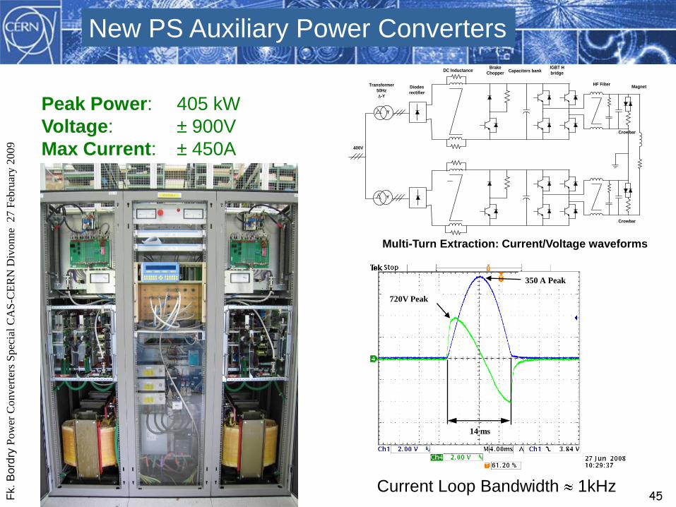
14 ms
350 A Peak
720V Peak
Current Loop Bandwidth 1kHz
Multi-Turn Extraction: Current/Voltage waveforms
Y
Y
Magnet
DC Inductance
Diodes
rectifier
Transformer
50Hz
-Y
Brake
ChopperCapacitors bank
IGBT H
bridge
HF Filter
400V
Crowbar
Crowbar
Peak Power: 405 kW
Voltage: ± 900V
Max Current: ± 450A
New PS Auxiliary Power Converters

Fk.
Bo
rdry
Pow
er C
onver
ters
Spec
ial
CA
S-C
ER
N D
ivonne
27 F
ebru
ary 2
009
46
Indirect AC-DC-AC-DC converter
+
-
DC-AC
HF
(Inverter)
AC-DC
HF
HF AC link
Three cascade power conversion stages:
1) Simple DC source (Diode (thyristor) rectifiers)
2) HF DC-AC converter (Inverter)
3) HF AC-DC converter (Rectifier) (often diode rectifier)
HF transformer to provide the galvanic isolation
DC link
AC-DC
LF

Fk.
Bo
rdry
Pow
er C
onver
ters
Spec
ial
CA
S-C
ER
N D
ivonne
27 F
ebru
ary 2
009
47
Voltage loop:
bandwidth few kHz
AC
50 Hz
AC
20 - 100 kHzDC DC
CV1 CV2 CV3 Magnet
HF
Fast power semiconductors
(IGBT)
Semiconductor losses :
soft commutation
HF transformer and output
filter : ferrite
• light weight, reduced volume (HF transformers and filters)
• good power factor (0.95)
• high bandwidth and good response time
• Soft commutation gives low losses and low electrical noise
• small residual current ripple at output
• More complex structure, less well understood, limited number of manufacturers
LHC Switch-Mode Power Converters
Passive high-current
Output stage

Fk.
Bo
rdry
Pow
er C
onver
ters
Spec
ial
CA
S-C
ER
N D
ivonne
27 F
ebru
ary 2
009
48
[2kA, 8V]MTBF and MTTR optimization
1-quadrant converters:
- [13kA,18V] : 5*[3.25kA,18V]
- [8kA,8V] : 5*[2kA,8V]
- [6kA,8V] : 4*[2kA,8V]
- [4kA,8V] : 3*[2kA,8V]
LHC:1-quadrant converter: modular approach

Fk.
Bo
rdry
Pow
er C
onver
ters
Spec
ial
CA
S-C
ER
N D
ivonne
27 F
ebru
ary 2
009
49
The load• Superconducting magnet: L= 7.5 H
• Nominal current: 20.5 kA
• Stored energy: 1.6 GJ
• Time constant: 37’500 s
The power converter : [20.5 kA, 18V] ; (7+1) x [3.25kA,18V]
20.5kA power converter for the ATLAS toroid

Fk.
Bo
rdry
Pow
er C
onver
ters
Spec
ial
CA
S-C
ER
N D
ivonne
27 F
ebru
ary 2
009
50
+
-
Transfo A2Pont thyr A2 self A2
self A2
Thyr décharge
C
+
-
Transfo B1Pont thyr B1 self B1
self B1
Thyr décharge
B
+
-
Transfo B2Pont thyr B2 self B2
self B2
Thyr décharge
D
+
-
Transfo A1Pont thyr A1 self A1
self A1
Thyr décharge
A
+
-
3~400V
20000 A
-23V ..
+26V+
-
Transfo A2Pont thyr A2 self A2
self A2
Thyr décharge
C+
-
Transfo A2Pont thyr A2 self A2
self A2
Thyr décharge
C
+
-
Transfo B1Pont thyr B1 self B1
self B1
Thyr décharge
B+
-
Transfo B1Pont thyr B1 self B1
self B1
Thyr décharge
B
+
-
Transfo B2Pont thyr B2 self B2
self B2
Thyr décharge
D+
-
Transfo B2Pont thyr B2 self B2
self B2
Thyr décharge
D
+
-
Transfo A1Pont thyr A1 self A1
self A1
Thyr décharge
A+
-
Transfo A1Pont thyr A1 self A1
self A1
Thyr décharge
A
+
-
3~400V
20000 A
-23V ..
+26V
The load• Superconducting magnet: L= 14H
• Nominal current: 20 kA
• Stored energy: 2.8 GJ
• Time constant: 39 hours
• Time for current ramping up: 3h15m
• Energy extraction system (resistor bank, not shown)
The power converter
20kA power converter for the CMS solenoid

Fk.
Bo
rdry
Pow
er C
onver
ters
Spec
ial
CA
S-C
ER
N D
ivonne
27 F
ebru
ary 2
009
51
PC1 Magnet
I
HF
1-quadrant converter
Difficult to
find suitable
switch
PC1
I
HF
K
PC2
4-quadrant converter
Vk
Ik
LHC:4-quadrant converter topology

Fk.
Bo
rdry
Pow
er C
onver
ters
Spec
ial
CA
S-C
ER
N D
ivonne
27 F
ebru
ary 2
009
52
[ 600A, ±10V]
2 converters per rack[ 600A, ±40V]
1 converter per rack
[ 120A, 8±V]
Up to 4 converters per rack
LHC:4-quadrant converters

Fk.
Bo
rdry
Pow
er C
onver
ters
Spec
ial
CA
S-C
ER
N D
ivonne
27 F
ebru
ary 2
009
53
High and medium power
Phase Controlled Rectifiers
- Diodes and thyristors rectifiers
- 50Hz transformers and magnetic
component (filters)
- 1-quadrant and 2-quadrants
(but unipolar in current) :
energy back to the mains
- 4-quadrant: back-to-back converters
Low and Medium power
Switch-mode power converters
- Mosfets , IGBTs, IGCTs,…
turn-off semiconductors
- HF transformers and passive filters
- excellent for 1-quadrant converter
- 4-quadrant converters but with energy
dissipation (very complex structure if
energy back to mains)
Rise and fall time < few ms
Control of the ramps
DC and slow pulsed converters
Fk.
Bo
rdry
Pow
er C
onver
ters
Spec
ial
CA
S-C
ER
N D
ivonne
27 F
ebru
ary 2
009
54
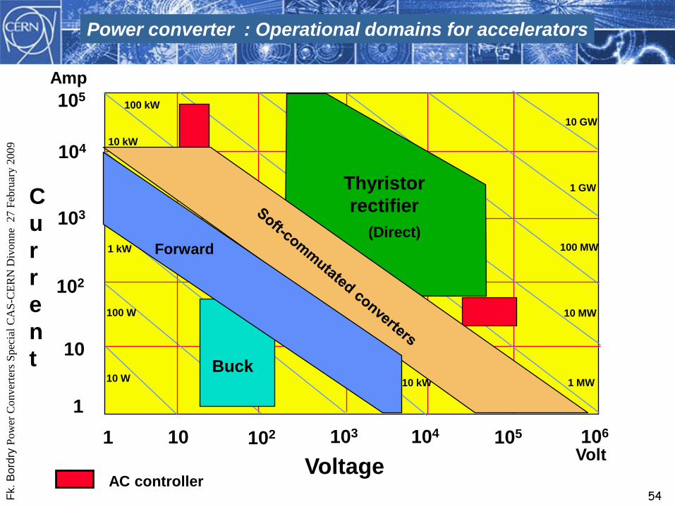
VoltageVolt
C
u
r
r
e
n
t
Amp
1 10 103 104 105 106102
10
102
103
104
105
1
10 W
100 W
10 kW
100 kW
1 MW
10 MW
100 MW
1 GWThyristor
rectifier
(Direct)
AC controller
Power converter : Operational domains for accelerators
Forward
Buck
1 kW
10 GW
10 kW

Fk.
Bo
rdry
Pow
er C
onver
ters
Spec
ial
CA
S-C
ER
N D
ivonne
27 F
ebru
ary 2
009
55
New PS power system (POPS)Fully static power converterExchange of energy between capacitor banks and the magnets
New Power converter for PS (60 MW)

Fk.
Bo
rdry
Pow
er C
onver
ters
Spec
ial
CA
S-C
ER
N D
ivonne
27 F
ebru
ary 2
009
56
Pulsed converters
Rise and fall time < few ms
Direct Energy transfer
from mains is not possible:
Intermediate storage of energy
Linac’s and transfer linesSynchrotrons
• Beam is injected, accelerated and
extracted in several turns;• Beam is passing through in one shot,
with a given time period;
t (s)
B (T),
I (A)
injection
acceleration
extraction
t (s)
B (T),
I (A)
Beam passage

Fk.
Bo
rdry
Pow
er C
onver
ters
Spec
ial
CA
S-C
ER
N D
ivonne
27 F
ebru
ary 2
009
57
Block schematic of a fast pulsed converter
CAPACITOR
CHARGER
POWER
CONVERTER
MAINS
DISCHARGE UNIT &
ENERGY RECOVER
SWITCHING MATRIX
LOAD
(MAGNET)ACTIVE
FILTER
CAPACITOR
BANK
CURRENT
REGULATORS
GA
IN
Uc
ha
rge
.re
f
Iload.ref
Iload
-
+
TIMING UNIT
Sta
rt / S
top
Ch
arg
e
Sta
rt / S
top
Ac
tiv
e F
ilte
r
Sta
rt D
isc
ha
rge
/
Sta
rt R
ec
ov
ery
Machine
Timing
Sta
rt C
ha
rge time
Pulses
Sto
p C
ha
rge
Sta
rt P
uls
e
Me
as
ure
Iload
Ucharge
Active filter “on”
Recovery

Fk.
Bo
rdry
Pow
er C
onver
ters
Spec
ial
CA
S-C
ER
N D
ivonne
27 F
ebru
ary 2
009
58
High current, high voltage discharge capacitor power converters
50 ms6 ms
150 kA for the horn
180 kA for the reflector

Fk.
Bo
rdry
Pow
er C
onver
ters
Spec
ial
CA
S-C
ER
N D
ivonne
27 F
ebru
ary 2
009
59
Power Converters for injection/extraction Septa magnets
• Characteristics :
- output current : 33.7 kA
- flat top stability < 3.10-4
- charging voltage : 2.1 kV
- 1 Hz repetition rate
ACTIVE FILTER
CHARGING CIRCUIT
MAINS MATCHINGTRANSFORMER
SEPTUM
L
R
HIGH VOLTAGE
LEIR RING
F.A. CMD
I septum
Fk.
Bo
rdry
Pow
er C
onver
ters
Spec
ial
CA
S-C
ER
N D
ivonne
27 F
ebru
ary 2
009
60
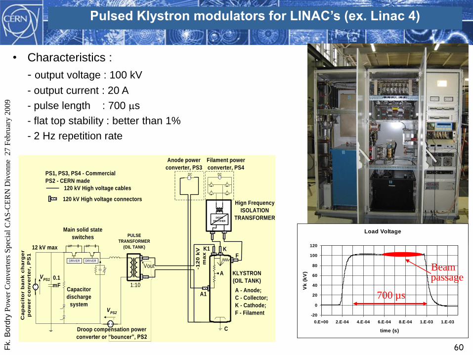
PULSE
TRANSFORMER
(OIL TANK)
Main solid state
switches
A1
C
KF
1:10
Ca
pa
cit
or b
an
k c
ha
rg
er
po
we
r c
on
ve
rte
r,
PS
1
Anode power
converter, PS3
A - Anode;
C - Collector;
K - Cathode;
F - Filament
Filament power
converter, PS4
Vout
Droop compensation power
converter or “bouncer”, PS2
0.1
mFCapacitor
discharge
system
VPS1
VPS2
12 kV max
-12
0 k
V
ma
x
KLYSTRON
(OIL TANK)
DC
Hign Frequency
ISOLATION
TRANSFORMER
DC
K1
PS1, PS3, PS4 - Commercial
PS2 - CERN made
120 kV High voltage cables
120 kV High voltage connectors
DIODE
RECTIFIER
A
DRIVER DRIVER
Pulsed Klystron modulators for LINAC’s (ex. Linac 4)
• Characteristics :
- output voltage : 100 kV
- output current : 20 A
- pulse length : 700 s
- flat top stability : better than 1%
- 2 Hz repetition rate
Load Voltage
-20
0
20
40
60
80
100
120
0.E+00 2.E-04 4.E-04 6.E-04 8.E-04 1.E-03 1.E-03
time (s)
Vk
(k
V)
Load Current
-5
0
5
10
15
20
25
0.E+00 2.E-04 4.E-04 6.E-04 8.E-04 1.E-03 1.E-03
time (s)
Vk
(k
V)
700 µs
Beam passage

Fk.
Bo
rdry
Pow
er C
onver
ters
Spec
ial
CA
S-C
ER
N D
ivonne
27 F
ebru
ary 2
009
61
Power Converter % Load
Load characteristics
are vital.
Transfer function is
the must !
TransducerControl
Loa
d
Power PartAC
Supply
Reference
Local control

Fk.
Bo
rdry
Pow
er C
onver
ters
Spec
ial
CA
S-C
ER
N D
ivonne
27 F
ebru
ary 2
009
62
?Iref BI
Imeas.
V
Power converter :Performance requirements

Fk.
Bo
rdry
Pow
er C
onver
ters
Spec
ial
CA
S-C
ER
N D
ivonne
27 F
ebru
ary 2
009
63
Accuracy Long term setting or measuring
uncertainty taking into consideration the
full range of permissible changes* of
operating and environmental conditions.
The accuracy is defined by default for a defined period (Ta)(e.g. one year)
The accuracy is expressed in ppm of INominal .
If the defined period (Ta) is too large, a calibration process
should be executed more often (e.g every month)
*requires definition :
(e.g. Electrical distribution system
perturbation, temperature variation,…)
INominal
IMeas. ± Accuracyppm
*INominal

Fk.
Bo
rdry
Pow
er C
onver
ters
Spec
ial
CA
S-C
ER
N D
ivonne
27 F
ebru
ary 2
009
64
Reproducibility
The reproducibility is defined by default for a period of time TRwithout any intervention affecting the calibrated parts (e.g. DCCT, ADC)
The reproducibility is expressed in ppm of INominal .
Cycle 1 Cycle 2 Cycle 3
T < TR
IB1IB2 IB3
IB2 = IB1 ± (Reproducibility pmm . Inominal )
IB3 = IB2 ± (Reproducibility pmm . Inominal )
Uncertainty in returning to a set of
previous working values from cycle
to cycle of the machine.
Fk.
Bo
rdry
Pow
er C
onver
ters
Spec
ial
CA
S-C
ER
N D
ivonne
27 F
ebru
ary 2
009
65
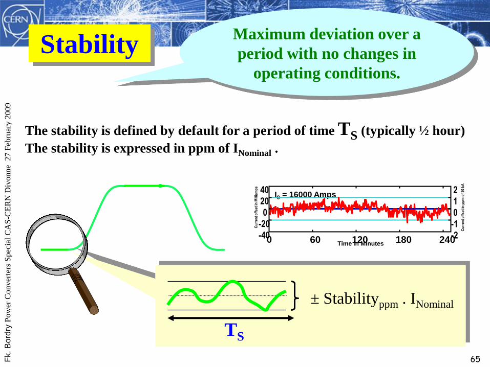
Stability Maximum deviation over a
period with no changes in
operating conditions.
The stability is defined by default for a period of time TS (typically ½ hour)
The stability is expressed in ppm of INominal .
± Stabilityppm . INominal
TS
Time in Minutes-40
-20
0
20
40
0 60 120 180 240-2
-1
0
1
2
Cu
rren
t off
set
in M
illia
mp
s
Cu
rren
t off
set
in p
pm
of
20 k
A
I0 = 16000 Amps

Fk.
Bo
rdry
Pow
er C
onver
ters
Spec
ial
CA
S-C
ER
N D
ivonne
27 F
ebru
ary 2
009
66
– AccuracyLong term setting or measuring uncertainty taking into consideration the full range of permissible changes* of operating and environmental conditions.
* requires definition
– ReproducibilityUncertainty in returning to a set of previous working values from cycle to cycle of the machine.
– StabilityMaximum deviation over a period with no changes in operating conditions.
Accuracy, reproducibility and stability are defined for a given period
GlossaryP
reci
sion
Precision is qualitative . Accuracy is quantitative.
INominal
IMeas. ± Accuracyppm
*INominal
TS
Cycle 1 Cycle 2 Cycle 3
TR
IB1 IB2 IB3

Fk.
Bo
rdry
Pow
er C
onver
ters
Spec
ial
CA
S-C
ER
N D
ivonne
27 F
ebru
ary 2
009
67
The most common current measurement technologies used in power converterapplications and the electrical principles behind them are summarised below:
Current measurement for power converter applications
• Resistive shunts, current sense resistors: Current to voltage conversion (Ohm’slaw)
• Hall effect current transducers: Based on the polarization of charges in an electrical conductor in the presence of an external magnetic field (Hall Effect).
• DCCTs: A zero flux detector (of the second harmonic or peak detector type) is used to generate a compensation current which is a fractional image of the current being measured. This current is converted to a voltage which is then measured.
•Current Transformers (CTs): Based on magnetic induction (Faraday law).
Rogowsky coils and Active CTs can also be found in current measurementapplications. These devices are based on similar principles to the ones listed above.Rogowsky coils can be particularly useful in very high current, high bandwidthapplications were saturation of CTs can be a problem.
Alternative measurement devices like Optical CTs are not so common but still used insome applications. Optical CTs make use of the Faraday effect (polarization of a beamof light by a magnetic field).

Fk.
Bo
rdry
Pow
er C
onver
ters
Spec
ial
CA
S-C
ER
N D
ivonne
27 F
ebru
ary 2
009
68
Accuracy Class: 10-2 to 10-3 (1% to 1000 ppm)
For this accuracy class, any of the technologies mentioned previously could be chosen. HoweverDCCTs are relatively expensive and “over qualified” for this class so they are not listed below:
Shunts- High Currents (tens to hundreds of kA) -> might require forced cooling for 10-2 accuracy- Medium Currents (up to the kA) -> might require forced cooling for 10-3 accuracy- In DC applications performance is limited by power and temperature coefficients- Low bandwidth. The AC performance is limited by parasitic components and by skin effect- No isolation from primary current circuit. Common mode might be a problem !
Hall effect transducers- Available for a wide range of currents (from hundreds of mA to tens of kA) and accuracies- Medium bandwidth (tens of kHz)- Provide isolation from the primary current circuit
CTs- Available for medium to high Currents (up to tens of kA) with accuracies of 0.5%- High bandwidth (up to the MHz) but no DC response- Provide isolation from the primary current circuit- Low maintenance (passive device)
Rogowsky coils- Available for very high currents (up to hundreds of kA) with 10-3 accuracy. No saturation- Very high bandwidth (up to tens of MHz) but no DC response- Provide isolation from the primary current circuit
Current measurement for power converter applications

Fk.
Bo
rdry
Pow
er C
onver
ters
Spec
ial
CA
S-C
ER
N D
ivonne
27 F
ebru
ary 2
009
69
Accuracy Class: 10-3 to 10-4 (1000 ppm to 100 ppm)
Shunts- Available for medium Currents (10A..1kA) at DC and 50/60Hz with accuracies to 500ppm- On the 1 to 100A range, a new generation of laboratory coaxial shunts has pushed the accuracy to 10-4
at frequencies up to 100kHz. Not viable for industrial applicatons.- Small currents (<10A) up to a few kHz can be measured close to 10-4 using current sensing resistors
(metal foil resistors are the most used)
DCCTs- Available for the medium to high current ranges (up to tens of kA) to 10-4
- Most suited for DC applications with tight accuracy requirements- AC response up to a few tens of kHz- Provide isolation from primary circuit
Accuracy Class: 10-4 to 10-5 (100 ppm to 10 ppm)
Current sense resistors- Can be used for small currents (<10A) at DC and AC (few kHz). Metal foil current sensing resistors are
suited for this range of accuracy. Particularly Zeranin foil resistors offer very low Temperature and PowerCoefficients and have a very low inductance.
DCCTs- Available for the medium to high current ranges (up to tens of kA) to 10-5
- Need good current sensing resistors to convert the compensation current into a measurable voltage- Factors like magnetic head design, output stage drift, thermal management, output noise become very
important at this level
Current measurement for power converter applications

Fk.
Bo
rdry
Pow
er C
onver
ters
Spec
ial
CA
S-C
ER
N D
ivonne
27 F
ebru
ary 2
009
70
Accuracy Class: 10-5 to 10-6 (10 ppm to 1 ppm)
Current sense resistors- Small currents (<10A) at DC and AC (some kHz). Special designs can achieve accuracies of a few ppm
but factors such as humidity, temperature, power dissipation, ageing and EMI mean that it is verydifficult to assure this performance outside a controlled environment.
DCCTs- Available for the medium to high current ranges (up to >kA) to better than 10-5.- High quality current sensing resistors are essential. ppm level performance is only possible to achieve in
a controlled environement.- Factors like head centering, head error, magnetic remanence become very important
Picture: Temperature controlledEMC Racks housing 6 electronicchassis for the 13kA HighPrecision DCCTs for the LHCmain power converters
Current measurement for power converter applications

Fk.
Bo
rdry
Pow
er C
onver
ters
Spec
ial
CA
S-C
ER
N D
ivonne
27 F
ebru
ary 2
009
71
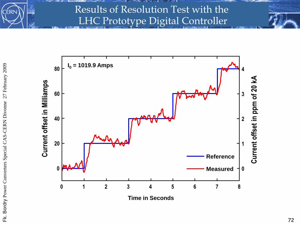
Resolution
The resolution is expressed in ppm of INominal .
Resolution is directly linked to A/D system
Smallest increment that can be
induced or discerned.
I*ref ± I*ref
ADC
DAC
Imeas + I.
V
IB
I*meas. ± I*
Fk.
Bo
rdry
Pow
er C
onver
ters
Spec
ial
CA
S-C
ER
N D
ivonne
27 F
ebru
ary 2
009
72
0
20
40
60
80
0 1 2 3 4 5 6 7 8
0
1
2
3
4
Cu
rren
t o
ffse
t in
Mill
iam
ps
Cu
rren
t o
ffse
t in
pp
m o
f 20
kA
Time in Seconds
I0 = 1019.9 Amps
Reference
Measured
Results of Resolution Test with the LHC Prototype Digital Controller

Fk.
Bo
rdry
Pow
er C
onver
ters
Spec
ial
CA
S-C
ER
N D
ivonne
27 F
ebru
ary 2
009
73
Tracking
Ability of the converters to follow the
reference function
(static, dynamics)
I1
I2
I3
Static part is covered by the static
definition :
accuracy, reproducibility
Dynamic part comes from :
- timing error
- lagging error in the regulation
Tracking error
between I1 and I2
Iref

Fk.
Bo
rdry
Pow
er C
onver
ters
Spec
ial
CA
S-C
ER
N D
ivonne
27 F
ebru
ary 2
009
74
Power converter LoadH(s)
V = R . I + L . dI/dt
=> H(s) = 1/ (L/R . s + 1)
Voltage ripple is defined by the power converter
Current ripple : load transfer function
(cables, magnet inductance,…)(good identification is required if the load is a long string of magnets )
RIPPLE
V I
Control
Magnet
F(s)
Field ripple : magnet transfer function (vacuum chamber,…)

Fk.
Bo
rdry
Pow
er C
onver
ters
Spec
ial
CA
S-C
ER
N D
ivonne
27 F
ebru
ary 2
009
75
Emission :IEC 61204-3 ( replaced IEC-60478-3)
(CISPR 11 ; EN 55011)
EMC : ELECTROMAGNETIC COMPATIBILITY
Norms for the power converters :
Immunity : IEC 61000 - 4 :
Burst 61000 - 4 - 4
Surge 61000- 4 - 5
COMPATIBILITY : Emission - Immunity

Fk.
Bo
rdry
Pow
er C
onver
ters
Spec
ial
CA
S-C
ER
N D
ivonne
27 F
ebru
ary 2
009
76
Interdisciplinary nature of power converters
Power
Converters
Solid-state
physics
Circuit
theory Systems and
control theory
Signal
Processing
Electronics
Electromagnetism
Power
Systems
Load
Modelling
Simulation and
computing
Fk.
Bo
rdry
Pow
er C
onver
ters
Spec
ial
CA
S-C
ER
N D
ivonne
27 F
ebru
ary 2
009
77
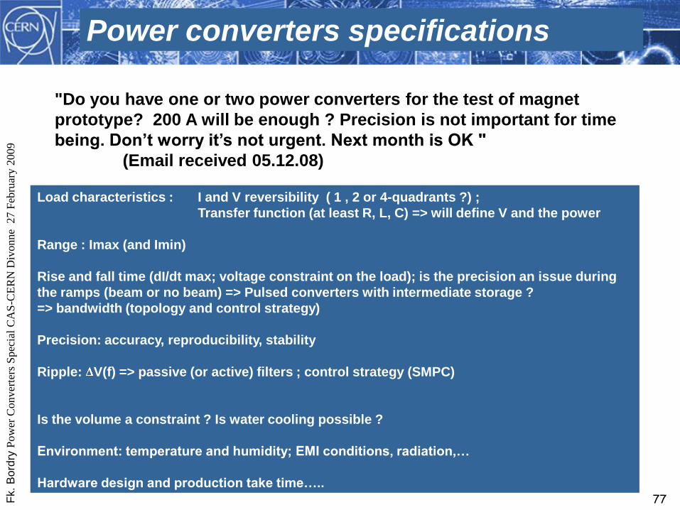
Power converters specifications
"Do you have one or two power converters for the test of magnet
prototype? 200 A will be enough ? Precision is not important for time
being. Don’t worry it’s not urgent. Next month is OK "
(Email received 05.12.08)
Load characteristics : I and V reversibility ( 1 , 2 or 4-quadrants ?) ;
Transfer function (at least R, L, C) => will define V and the power
Range : Imax (and Imin)
Rise and fall time (dI/dt max; voltage constraint on the load); is the precision an issue during
the ramps (beam or no beam) => Pulsed converters with intermediate storage ?
=> bandwidth (topology and control strategy)
Precision: accuracy, reproducibility, stability
Ripple: V(f) => passive (or active) filters ; control strategy (SMPC)
Is the volume a constraint ? Is water cooling possible ?
Environment: temperature and humidity; EMI conditions, radiation,…
Hardware design and production take time…..

Fk.
Bo
rdry
Pow
er C
onver
ters
Spec
ial
CA
S-C
ER
N D
ivonne
27 F
ebru
ary 2
009
78
CAS - CERN Accelerator School :
Power converters for particle accelerators26 - 30 Mar 1990, Switzerland
CERN Accelerator School and CLRC Daresbury Laboratory :
Specialised CAS Course on
Power Converters for particle accelerators12 - 18 May 2004 - Warrington, UK