Power and Data Pole - UPLIFT Desk
8
For further info or assistance, visit upliftdesk.com call 800-349-3839 or email [email protected] Patent Pending, ©2020 UPLIFT Desk®. All Rights Reserved two person assembly Power and Data Pole ®
Transcript of Power and Data Pole - UPLIFT Desk

For further info or assistance, visit upliftdesk.comcall 800-349-3839 or email [email protected] Pending, ©2020 UPLIFT Desk®. All Rights Reserved
355 lb
two person assembly
Power and Data Pole
®

Thank you for choosing UPLIFT Desk.
SAFETY AND WARNINGS
WARNING: Designed for use in dry work environments only. Risk of fire, electric shock, or personal in-jury if used outdoors or in a damp location. Use only indoors.
WARNING: To reduce the risk of burns, fire or electric shock, hard wiring of power infeed cables must be performed by a licensed electrician only in accordance with the NEC and local codes. All connections must be properly grounded.
WARNING: Do not open any component or insert any object in a component. Risk of electric shock.
WARNING: Never operate this product if there is visible damage to the cables or connections, if it is not working properly, or if any part of it has been exposed to water or other liquids.
WARNING: Use this system only as described in these instructions and do not use with any components not recommended by the manufacturer.
Please read this manual carefully. Inappropriate use can cause property damage or bodily injury. Under no cir-cumstances does the manufacturer accept warranty or liability claims for damages caused from improper use or handling. Provide this manual to any new user.

The Power and Data Pole can be installed at the end of a Power and Data Rail row or in the middle of a row, between the desks as shown in the diagrams below.
The feet of the Power and Data Rail posts help to position the feet of the UPLIFT V2 desk frames so that there is a 4 inch gap between desks from side to side and from back to back.
If you purchased the Power and Data Pole without desks, but with the optional Rail addition, your assem-bly will look like the top, left image below.
End of row installation
Middle of row installation

© UPLIFT Desk • 800-349-3839 • 512-614-3152 • [email protected] • upliftdesk.com4
Ceiling plateInner pole Outer Pole
Alignment post
Clamp bracket(qty 2) M5x12 Machine screw
(qty 10)Adhesive pads
(qty 2)
3mm Allen wrenchThread-cutting screw(qty 4)
Post bracket Alignment plate
Package Contents
Step 2Attach the Post bracket to the Outer pole in the orientation shown here using four of the M5x12 Machine screws. Start all four screws loosely by hand and then tighten using the 3mm Allen wrench. Do not over tighten to avoid stripping.
Step 3Attach the Alignment bracket to the Alignment post as shown here using three more of the M5x12 Machine screws. Once again, start all three screws loosely by hand before tightening with the 3mm Allen wrench. Be careful to not over tighten.
Step 1Begin by determining where your power and data drops will be located. Figure out where the closest junction box in the ceil-ing is located. The Power Pole was designed to conceal power and data cables running from the ceiling down to the UPLIFT Power and Data Rail when floor or wall power sources are not available.
The Power Pole is a telescoping design that works with ceil-ings between 8 and 12 feet high. Included with the Power Pole assembly is a 216-inch long hardwired flexible conduit power infeed cable. Cable connections require a licensed electrician and the length can be shortened as needed during assembly and installation.
Power Poles attach to the Power and Data Rail square posts, so the location of the Power Poles and power drops should be con-sidered when designing your Power and Data Rail configuration.
One Power Pole and Power infeed cable can provide power to up to 16 desks using four 20 amp circuits (up to four desks per individual 20 amp circuit).
ITEM
NO.
PART
NUM
BER
DESCR
IPTI
ON
QTY.
1
1
PRT0
0197
MAI
N POLE
1
2
2
PRT0
0199
POW
ER P
OLE, B
RACK
ET, S
T
1
3
3 (x
10)
9035
8A01
2
9035
8A01
2_M
ETRI
C ST
L ULT
RA-
LOW
-PRO
FILE
SCK
T HEA
D SCR
EW
10
4
4
PRT0
0212
POW
ER P
OLE, C
LAM
P, S
T
2
5
5
6
PRT0
0200
POW
ER P
OLE, L
OWER
TUBE
, AL
1
6
PRT0
0207
POW
ER P
OLE, B
RACK
ET, L
OWER
, ST
1
7
7
PRT0
0198
POW
ER P
OLE, IN
NER, A
L
1
89
9 (x
2)
8
PRT0
0206
???
POW
ER P
OLE, C
EILI
NG PLT
, AL
Prev
ious
ly u
nmen
tione
d sc
rew
s
12
1
2
3 (x
2)
3 (x
5)9
(x2)
3 (x
3)
4 (x
2)
5
6
7
8
1
2
3 (x
10)
4
5
6
7
9 (x
2)
8
1
2
3 (x
2)
3 (x
5)9
(x2)
3 (x
3)
4 (x
2)
5
6
7
8IT
EM N
O.
PART
NUM
BER
DESCR
IPTI
ON
QTY.
1
1
PRT0
0197
MAI
N POLE
1
2
2
PRT0
0199
POW
ER P
OLE, B
RACK
ET, S
T
1
3
3 (x
10)
9035
8A01
2
9035
8A01
2_M
ETRI
C ST
L ULT
RA-
LOW
-PRO
FILE
SCK
T HEA
D SCR
EW
10
4
4
PRT0
0212
POW
ER P
OLE, C
LAM
P, S
T
2
5
5
6
PRT0
0200
POW
ER P
OLE, L
OWER
TUBE
, AL
1
6
PRT0
0207
POW
ER P
OLE, B
RACK
ET, L
OWER
, ST
1
7
7
PRT0
0198
POW
ER P
OLE, IN
NER, A
L
1
89
9 (x
2)
8
PRT0
0206
???
POW
ER P
OLE, C
EILI
NG PLT
, AL
Prev
ious
ly u
nmen
tione
d sc
rew
s
12
1
2
3 (x
2)
3 (x
5)9
(x2)
3 (x
3)
4 (x
2)
5
6
7
8
1
2
3 (x
10)
4
5
6
7
9 (x
2)
8
1
2
3 (x
2)
3 (x
5)9
(x2)
3 (x
3)
4 (x
2)
5
6
7
8
ITEM NO. PART NUMBER DESCRIPTION QTY.1
1
PRT00197 MAIN POLE 12
2
PRT00199 POWER POLE, BRACKET, ST 1
3
3 (x10)
90358A012 90358A012_METRIC STL ULTRA-LOW-PROFILE SCKT HEAD SCREW 10
4
4
PRT00212 POWER POLE, CLAMP, ST 25
5 6
PRT00200 POWER POLE, LOWER TUBE, AL 16 PRT00207 POWER POLE, BRACKET, LOWER, ST 17
7
PRT00198 POWER POLE, INNER, AL 18
9
9 (x2)8
PRT00206
???
POWER POLE, CEILING PLT, AL
Previously unmentioned screws
1
2
1
2
3 (x2)
3 (x5)
9 (x2)
3 (x3)
4 (x2)
5
6
7
8
1 2 3 (x10)4 5 67 9 (x2)8
1
2
3 (x2)
3 (x5)
9 (x2)
3 (x3)
4 (x2)
5
6
7
8
ITEM N
O.
PART N
UM
BERD
ESCRIPTION
QTY.
1
1
PRT00197M
AIN
POLE
1
2
2
PRT00199PO
WER PO
LE, BRACKET, ST
1
3
3 (x10)
90358A012
90358A012_M
ETRIC STL ULTRA
-LO
W-PRO
FILE SCKT HEA
D SCREW
10
4
4
PRT00212PO
WER PO
LE, CLAM
P, ST2
5
56
PRT00200PO
WER PO
LE, LOW
ER TUBE, A
L1
6PRT00207
POW
ER POLE, BRA
CKET, LOW
ER, ST1
7
7
PRT00198PO
WER PO
LE, INN
ER, AL
1
89
9 (x2)8
PRT00206
???
POW
ER POLE, CEILIN
G PLT, A
L
Previously unmentioned screw
s
12
1
2
3 (x2)
3 (x5)
9 (x2)
3 (x3)
4 (x2)
5
6
7 8
12
3 (x10)4
56
79 (x2)
8
1
2
3 (x2)
3 (x5)
9 (x2)
3 (x3)
4 (x2)
5
6
7 8
ITEM N
O.
PART N
UM
BERD
ESCRIPTION
QTY.
1
1
PRT00197M
AIN
POLE
1
2
2
PRT00199PO
WER PO
LE, BRACKET, ST
1
3
3 (x10)
90358A012
90358A012_M
ETRIC STL ULTRA
-LO
W-PRO
FILE SCKT HEA
D SCREW
10
4
4
PRT00212PO
WER PO
LE, CLAM
P, ST2
5
56
PRT00200PO
WER PO
LE, LOW
ER TUBE, A
L1
6PRT00207
POW
ER POLE, BRA
CKET, LOW
ER, ST1
7
7
PRT00198PO
WER PO
LE, INN
ER, AL
1
89
9 (x2)8
PRT00206
???
POW
ER POLE, CEILIN
G PLT, A
L
Previously unmentioned screw
s
12
1
2
3 (x2)
3 (x5)
9 (x2)
3 (x3)
4 (x2)
5
6
7 8
12
3 (x10)4
56
79 (x2)
8
1
2
3 (x2)
3 (x5)
9 (x2)
3 (x3)
4 (x2)
5
6
7 8ITEM NO. PART NUMBER DESCRIPTION QTY.
1
1
PRT00197 MAIN POLE 1
2
2
PRT00199 POWER POLE, BRACKET, ST 1
3
3 (x10)
90358A012 90358A012_METRIC STL ULTRA-LOW-PROFILE SCKT HEAD SCREW 10
4
4
PRT00212 POWER POLE, CLAMP, ST 2
5
5 6
PRT00200 POWER POLE, LOWER TUBE, AL 1
6 PRT00207 POWER POLE, BRACKET, LOWER, ST 1
7
7
PRT00198 POWER POLE, INNER, AL 1
8
9
9 (x2)8
PRT00206
???
POWER POLE, CEILING PLT, AL
Previously unmentioned screws
1
2
1
2
3 (x2)
3 (x5)
9 (x2)
3 (x3)
4 (x2)
5
6
7
8
1 2 3 (x10)4 5 67 9 (x2)8
1
2
3 (x2)
3 (x5)
9 (x2)
3 (x3)
4 (x2)
5
6
7
8
ITEM NO. PART NUMBER DESCRIPTION QTY.
1
1
PRT00197 MAIN POLE 1
2
2
PRT00199 POWER POLE, BRACKET, ST 1
3
3 (x10)
90358A012 90358A012_METRIC STL ULTRA-LOW-PROFILE SCKT HEAD SCREW 10
4
4
PRT00212 POWER POLE, CLAMP, ST 2
5
5 6
PRT00200 POWER POLE, LOWER TUBE, AL 1
6 PRT00207 POWER POLE, BRACKET, LOWER, ST 1
7
7
PRT00198 POWER POLE, INNER, AL 1
8
9
9 (x2)8
PRT00206
???
POWER POLE, CEILING PLT, AL
Previously unmentioned screws
1
2
1
2
3 (x2)
3 (x5)
9 (x2)
3 (x3)
4 (x2)
5
6
7
8
1 2 3 (x10)4 5 67 9 (x2)8
1
2
3 (x2)
3 (x5)
9 (x2)
3 (x3)
4 (x2)
5
6
7
8ITEM NO. PART NUMBER DESCRIPTION QTY.
1
1
PRT00197 MAIN POLE 1
2
2
PRT00199 POWER POLE, BRACKET, ST 1
3
3 (x10)
90358A012 90358A012_METRIC STL ULTRA-LOW-PROFILE SCKT HEAD SCREW 10
4
4
PRT00212 POWER POLE, CLAMP, ST 2
5
5 6
PRT00200 POWER POLE, LOWER TUBE, AL 1
6 PRT00207 POWER POLE, BRACKET, LOWER, ST 1
7
7
PRT00198 POWER POLE, INNER, AL 1
8
9
9 (x2)8
PRT00206
???
POWER POLE, CEILING PLT, AL
Previously unmentioned screws
1
2
1
2
3 (x2)
3 (x5)
9 (x2)
3 (x3)
4 (x2)
5
6
7
8
1 2 3 (x10)4 5 67 9 (x2)8
1
2
3 (x2)
3 (x5)
9 (x2)
3 (x3)
4 (x2)
5
6
7
8
Power Infeed cable(216 in.)
C3 C4 C5
C9
H4a
H7
C6
H1 H2 H3 H5
H4b
H6
C7
ITEM
NO
.PA
RT N
UM
BER
DES
CRIP
TIO
NQ
TY.
1
1
PRT0
0197
MA
IN P
OLE
1
2
2
PRT0
0199
POW
ER P
OLE
, BRA
CKET
, ST
1
3
3 (x
10)
9035
8A01
290
358A
012_
MET
RIC
STL
ULT
RA-
LOW
-PRO
FILE
SCK
T H
EAD
SCR
EW10
4
4
PRT0
0212
POW
ER P
OLE
, CLA
MP,
ST
2
5
56
PRT0
0200
POW
ER P
OLE
, LO
WER
TU
BE, A
L1
6PR
T002
07PO
WER
PO
LE, B
RACK
ET, L
OW
ER, S
T1
7
7
PRT0
0198
POW
ER P
OLE
, IN
NER
, AL
1
8 9
9 (x
2)8
PRT0
0206
???
POW
ER P
OLE
, CEI
LIN
G P
LT, A
L
Prev
ious
ly u
nmen
tione
d sc
rew
s
1 2
1
2
3 (x
2)
3 (x
5)
9 (x
2)
3 (x
3)
4 (x
2)
5
6
78
12
3 (x
10)
45
67
9 (x
2)8
1
2
3 (x
2)
3 (x
5)
9 (x
2)
3 (x
3)
4 (x
2)
5
6
78IT
EM N
O.
PART
NU
MBE
RD
ESCR
IPTI
ON
QTY
.
1
1
PRT0
0197
MA
IN P
OLE
1
2
2
PRT0
0199
POW
ER P
OLE
, BRA
CKET
, ST
1
3
3 (x
10)
9035
8A01
290
358A
012_
MET
RIC
STL
ULT
RA-
LOW
-PRO
FILE
SCK
T H
EAD
SCR
EW10
4
4
PRT0
0212
POW
ER P
OLE
, CLA
MP,
ST
2
5
56
PRT0
0200
POW
ER P
OLE
, LO
WER
TU
BE, A
L1
6PR
T002
07PO
WER
PO
LE, B
RACK
ET, L
OW
ER, S
T1
7
7
PRT0
0198
POW
ER P
OLE
, IN
NER
, AL
1
8 9
9 (x
2)8
PRT0
0206
???
POW
ER P
OLE
, CEI
LIN
G P
LT, A
L
Prev
ious
ly u
nmen
tione
d sc
rew
s
1 2
1
2
3 (x
2)
3 (x
5)
9 (x
2)
3 (x
3)
4 (x
2)
5
6
78
12
3 (x
10)
45
67
9 (x
2)8
1
2
3 (x
2)
3 (x
5)
9 (x
2)
3 (x
3)
4 (x
2)
5
6
78
ITEM
NO
.PA
RT N
UM
BER
DES
CRIP
TIO
NQ
TY.
1
1
PRT0
0197
MA
IN P
OLE
1
2
2
PRT0
0199
POW
ER P
OLE
, BRA
CKET
, ST
1
3
3 (x
10)
9035
8A01
290
358A
012_
MET
RIC
STL
ULT
RA-
LOW
-PRO
FILE
SCK
T H
EAD
SCR
EW10
4
4
PRT0
0212
POW
ER P
OLE
, CLA
MP,
ST
2
5
56
PRT0
0200
POW
ER P
OLE
, LO
WER
TU
BE, A
L1
6PR
T002
07PO
WER
PO
LE, B
RACK
ET, L
OW
ER, S
T1
7
7
PRT0
0198
POW
ER P
OLE
, IN
NER
, AL
1
8 9
9 (x
2)8
PRT0
0206
???
POW
ER P
OLE
, CEI
LIN
G P
LT, A
L
Prev
ious
ly u
nmen
tione
d sc
rew
s
1 2
1
2
3 (x
2)
3 (x
5)
9 (x
2)
3 (x
3)
4 (x
2)
5
6
78
12
3 (x
10)
45
67
9 (x
2)8
1
2
3 (x
2)
3 (x
5)
9 (x
2)
3 (x
3)
4 (x
2)
5
6
78

© UPLIFT Desk • 800-349-3839 • 512-614-3152 • [email protected] • upliftdesk.com 5
Step 5At the locations where the power and data drops will be locat-ed on the ceiling, use the Ceiling plate as a template to create an outline for cutting your hole.
Then using a box cutter blade or drywall saw, carefully cut along the marked hole just to the outside of your marked lines so there is some clearance for the pole.
Once your hole is cut, carefully remove the material from the center of the cut lines and, from the floor side of the ceiling, insert the Ceiling plate. Hold the Ceiling plate in the hole, and bend over the tabs to hold the plate in place.
Repeat these steps for any remaining power and data drop lo-cations.
Step 6If you plan to attach a junction box or other wiring connections through the top of the pole, be aware there is a 1/2” diameter hole at one end and a 3/4” diameter hole at the other end of the Inner pole. The end with the hole you choose will be the “top.”
On the side opposite the hole at the “bottom” place an Adhe-sive pad to reduce rattling. Remove the backing from an Adhe-sive pad and place it lengthwise as shown. Press firmly to keep it from peeling off when sliding into the Outer pole.
With both poles laying flat, slide the Inner pole into the Outer pole from the end opposite where the Post bracket is attached. Slide the poles all the way together until the Inner pole stops. Be careful not to slide the Inner pole in forcefully or it could damage the threaded inserts inside of the Outer pole.
1/2” diameter 3/4” diameter
End of row installation Middle of row installation Step 4Position the Alignment post assembly from the previous step with the Alignment bracket between the bottom of one of the Power and Data Rail Square posts and a Post foot as shown here. Notice the difference in location of the Alignment post and plate when installing a Power and Data Pole at the end of a Power and Data Rail verses installing in the middle of a Power and Data Rail. Then, using the four M5 Flat head screws that came with the Square post, attach the Post foot to the Square post. As before, start all four screws loosely by hand before tightening with the 3mm Allen wrench.
If you are installing more than one Power Pole, follow Steps 2 and 3 for the remaining Power Poles at this time.
Then move the assemblies to the approximate locations below where the power and data drops will be.
Note: Be sure the Square post height is set before attaching the Alignment post assembly. See the instructions that came with your Power and Data Rail for post height settings.

© UPLIFT Desk • 800-349-3839 • 512-614-3152 • [email protected] • upliftdesk.com6
Step 8With one person on the ground holding the pole assembly up-right, a second person on a ladder can slowly slide the Inner pole up through the hole and Ceiling plate in the ceiling above.
Once the Inner pole is 4 to 6 inches through the hole in the ceiling, lock the Inner and Outer poles together with one of the following two options:
Option 1: Place the Clamp brackets around the Inner pole di-rectly above the Outer pole and attach them together using the remaining two M5x12 Machine screws.
After the Clamp brackets have been installed around the In-ner pole, raise it up slightly and apply a second Adhesive pad as shown directly under the brackets and slide the Inner pole down into the Outer pole.
Option 2: Use the remaining two Thread-cutting screws to at-tach the Outer pole to the Inner pole through the small holes in the top of the Outer pole.
IMPORTANT: Do NOT use Option 2 if you are running data ca-bles down through the Power Pole. The Thread-cutting screws may damage the data cables.
Option 1
Option 2
Step 7Note: We recommend using two people for the remainder of the Power Pole assembly.
Move the Inner and Outer pole assembly to the Power and Data Rail post it will be attached to. Be careful when moving the poles so that they do not slide apart. Carefully tip the pole as-sembly upright and position it along the Square post and above the short Alignment post.
Slide the pole assembly down over the Alignment post until the Post bracket is resting on the top of the Square post as shown.
Once in place, use one M5x12 Machine screw to attach the Alignment bracket to the top of the Square post and use two Thread-cutting screws to attach the Outer pole to the Align-ment post.
Step 9The final step of the Power Pole installation is to run your ca-bles. If you are installing both power and data cables, install the Power infeed cable first.
The person above on the ladder should move one of the dropped ceiling panels aside and then begin to feed the Power infeed cable down through the top of the Power Pole with the connector end first.
Continue to feed the cable down through the pole assembly until the person on the floor sees the connector through the opening at the top of the Square post. As the person on the floor begins to route the Power Infeed cable through the opposite side of the Square post, continue to feed cable down through the Power pole until there is about 1 to 2 feet coming out of the post.
Note, route the Power infeed cable through one of the side open-ings in the Square post (90 degrees from the Power and Data Pole) for installations in the middle of a Power and Data Rail row.
Steps 7 through 10 show the installation of the Power and Data Pole at the end of a Power and Data Rail row. Installation of the Power and Data Pole in the middle of a row follows the same basic steps, except that the Pole attaches to the post adjacent to a Rail instead of the opposite side of a Rail.
© UPLIFT Desk • 800-349-3839 • 512-614-3152 • [email protected] • upliftdesk.com 7
Step 10Follow the instructions included with your Power and Data Rail to begin adding rails and additional posts to your configuration.
Once the first Rail is in place, the length of cable coming out of the Power Pole can be adjusted as needed to reach the Power block in the rail. After the Power Infeed connection is made to the Power block in the Rail, the excess cable above the ceil-ing can be trimmed or coiled and electrical connections can be made.
As noted in Step 6, the hole at the top of the Power Pole can be used for attachment of a junction box or other wiring con-nections.
To complete the wiring, have a licensed electrician connect the “AC-95” 90° connector at the end of the Power infeed cable to a 1/2” diameter knockout on the junction box and make the applicable wiring connections.
ITEM
NO
.PA
RT N
UM
BER
DES
CRIP
TIO
NQ
TY.
1
1
PRT0
0197
MA
IN P
OLE
1
2
2
PRT0
0199
POW
ER P
OLE
, BRA
CKET
, ST
1
3
3 (x
10)
9035
8A01
290
358A
012_
MET
RIC
STL
ULT
RA-
LOW
-PRO
FILE
SCK
T H
EAD
SCR
EW10
4
4
PRT0
0212
POW
ER P
OLE
, CLA
MP,
ST
2
5
56
PRT0
0200
POW
ER P
OLE
, LO
WER
TU
BE, A
L1
6PR
T002
07PO
WER
PO
LE, B
RACK
ET, L
OW
ER, S
T1
7
7
PRT0
0198
POW
ER P
OLE
, IN
NER
, AL
1
8 9
9 (x
2)8
PRT0
0206
???
POW
ER P
OLE
, CEI
LIN
G P
LT, A
L
Prev
ious
ly u
nmen
tione
d sc
rew
s
1 2
1
2
3 (x
2)
3 (x
5)
9 (x
2)
3 (x
3)
4 (x
2)
5
6
78
12
3 (x
10)
45
67
9 (x
2)8
1
2
3 (x
2)
3 (x
5)
9 (x
2)
3 (x
3)
4 (x
2)
5
6
78IT
EM N
O.
PART
NU
MBE
RD
ESCR
IPTI
ON
QTY
.
1
1
PRT0
0197
MA
IN P
OLE
1
2
2
PRT0
0199
POW
ER P
OLE
, BRA
CKET
, ST
1
3
3 (x
10)
9035
8A01
290
358A
012_
MET
RIC
STL
ULT
RA-
LOW
-PRO
FILE
SCK
T H
EAD
SCR
EW10
4
4
PRT0
0212
POW
ER P
OLE
, CLA
MP,
ST
2
5
56
PRT0
0200
POW
ER P
OLE
, LO
WER
TU
BE, A
L1
6PR
T002
07PO
WER
PO
LE, B
RACK
ET, L
OW
ER, S
T1
7
7
PRT0
0198
POW
ER P
OLE
, IN
NER
, AL
1
8 9
9 (x
2)8
PRT0
0206
???
POW
ER P
OLE
, CEI
LIN
G P
LT, A
L
Prev
ious
ly u
nmen
tione
d sc
rew
s
1 2
1
2
3 (x
2)
3 (x
5)
9 (x
2)
3 (x
3)
4 (x
2)
5
6
78
12
3 (x
10)
45
67
9 (x
2)8
1
2
3 (x
2)
3 (x
5)
9 (x
2)
3 (x
3)
4 (x
2)
5
6
78
ITEM
NO
.PA
RT N
UM
BER
DES
CRIP
TIO
NQ
TY.
1
1
PRT0
0197
MA
IN P
OLE
1
2
2
PRT0
0199
POW
ER P
OLE
, BRA
CKET
, ST
1
3
3 (x
10)
9035
8A01
290
358A
012_
MET
RIC
STL
ULT
RA-
LOW
-PRO
FILE
SCK
T H
EAD
SCR
EW10
4
4
PRT0
0212
POW
ER P
OLE
, CLA
MP,
ST
2
5
56
PRT0
0200
POW
ER P
OLE
, LO
WER
TU
BE, A
L1
6PR
T002
07PO
WER
PO
LE, B
RACK
ET, L
OW
ER, S
T1
7
7
PRT0
0198
POW
ER P
OLE
, IN
NER
, AL
1
8 9
9 (x
2)8
PRT0
0206
???
POW
ER P
OLE
, CEI
LIN
G P
LT, A
L
Prev
ious
ly u
nmen
tione
d sc
rew
s
1 2
1
2
3 (x
2)
3 (x
5)
9 (x
2)
3 (x
3)
4 (x
2)
5
6
78
12
3 (x
10)
45
67
9 (x
2)8
1
2
3 (x
2)
3 (x
5)
9 (x
2)
3 (x
3)
4 (x
2)
5
6
78“AC-95” 90° connector
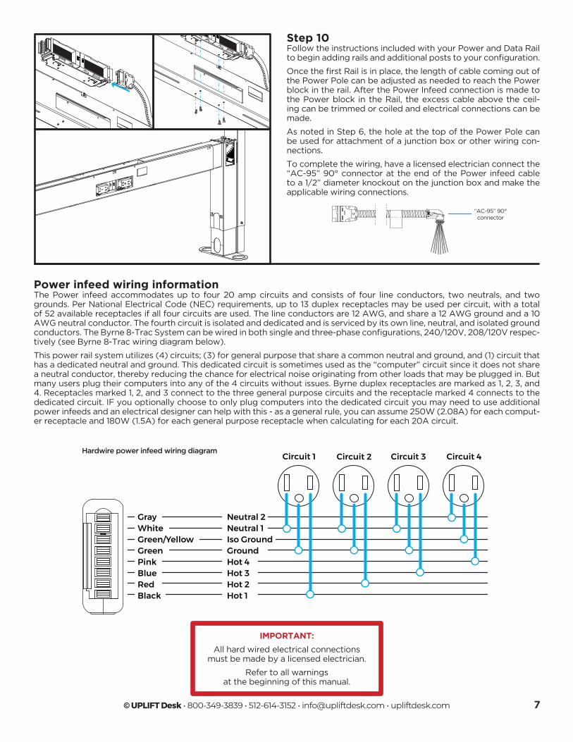
Power infeed wiring informationThe Power infeed accommodates up to four 20 amp circuits and consists of four line conductors, two neutrals, and two grounds. Per National Electrical Code (NEC) requirements, up to 13 duplex receptacles may be used per circuit, with a total of 52 available receptacles if all four circuits are used. The line conductors are 12 AWG, and share a 12 AWG ground and a 10 AWG neutral conductor. The fourth circuit is isolated and dedicated and is serviced by its own line, neutral, and isolated ground conductors. The Byrne 8-Trac System can be wired in both single and three-phase configurations, 240/120V, 208/120V respec-tively (see Byrne 8-Trac wiring diagram below).
This power rail system utilizes (4) circuits; (3) for general purpose that share a common neutral and ground, and (1) circuit that has a dedicated neutral and ground. This dedicated circuit is sometimes used as the “computer” circuit since it does not share a neutral conductor, thereby reducing the chance for electrical noise originating from other loads that may be plugged in. But many users plug their computers into any of the 4 circuits without issues. Byrne duplex receptacles are marked as 1, 2, 3, and 4. Receptacles marked 1, 2, and 3 connect to the three general purpose circuits and the receptacle marked 4 connects to the dedicated circuit. IF you optionally choose to only plug computers into the dedicated circuit you may need to use additional power infeeds and an electrical designer can help with this - as a general rule, you can assume 250W (2.08A) for each comput-er receptacle and 180W (1.5A) for each general purpose receptacle when calculating for each 20A circuit.
Hardwire power infeed wiring diagramCircuit 1 Circuit 2 Circuit 3 Circuit 4
GrayWhiteGreen/YellowGreenPinkBlueRedBlack
Neutral 2Neutral 1Iso GroundGroundHot 4Hot 3Hot 2Hot 1
IMPORTANT:
All hard wired electrical connections must be made by a licensed electrician.
Refer to all warnings at the beginning of this manual.

Copyright Notice: This guide is a component of this UPLIFT Desk Acoustics Product. This guide is a part of the scope of delivery, even if the item is resold. This guide is also available on the UPLIFT Desk website: upliftdesk.com. Excerpts or copies may not be forwarded to third parties or used in any other published form without the prior written consent of UPLIFT Desk. These instructions are subject to United States copyright law.
©
SAVE THESE INSTRUCTIONSStudy this manual carefully. If this desk is sold, please provide this manual to the buyer, installers, or support personnel operating the product.
AI-PDC005-PWR-PL-1.1
®
40030619v.B