


UPLIFT 2-Leg Height Adjustable Standing Desk · UPLIFT 2-Leg Height Adjustable Standing Desk ... 3...
12
DIRECTIONS FOR ASSEMBLY AND USE 90.014.01.0158v.G UPLIFT 2-Leg Height Adjustable Standing Desk (Version v4 Control Box) ® Also watch our assembly video http://bit.ly/2qvkeUF SAVE THESE INSTRUCTIONS: Any user or installer of desk base must study this manual carefully. If this desk is sold, please provide the manual to the buyer, installers, or support personnel operating the product. TABLE OF CONTENTS PAGE 1 Safety and Warnings 2 2 Usage 2 3 Parts List 3 4 Assembly Instructions 4 5 Desk Placement 7 6 Programming 7 7 Troubleshooting 9 8 Technical Specifications 9 FRM200/R06 4933053179415 - THS607
Transcript of UPLIFT 2-Leg Height Adjustable Standing Desk · UPLIFT 2-Leg Height Adjustable Standing Desk ... 3...
DIRECTIONS FOR ASSEMBLY AND USE
90.014.01.0158v.G
UPLIFT 2-Leg Height Adjustable Standing Desk(Version v4 Control Box)
®
Also watch our assembly video
http://bit.ly/2qvkeUF
SAVE THESE INSTRUCTIONS: Any user or installer of desk base must study this manual carefully. If this desk is sold,
please provide the manual to the buyer, installers, or support personnel operating the product.
TABLE OF CONTENTS PAGE
1 Safety and Warnings 22 Usage 23 Parts List 34 Assembly Instructions 45 Desk Placement 76 Programming 77 Troubleshooting 98 TechnicalSpecifications 9
FRM200/R06
UPLIFT Height Adjustable Standing Desk Step-by-...https://www.youtube.com/watch?v=Kk8UgqpEoBg
http://kaywa.me/n8M0D
Download the Kaywa QR Code Reader (App Store &Android Market) and scan your code!
4933053179415 - THS607
© UPLIFT Desk • 1-800-349-3839 • [email protected] • www.upliftdesk.com2
This height adjustable desk has an electric motor and is designed for use in dry work areas only. The desk height is adjustable so that it can be positioned at the most ergonomically suitable height. These desks are designed only for the purposes included in this manual. They should not be used in environments with high humidity or dampness. Any other use is at user’s risk.
Do not move around, crawl, or lie under the desk frame. Do not sit or stand on the desk frame.
Children should never use the desk unless they are supervised by adults.
Liability: Under no circumstances does the manufacturer accept warranty claims or liability claims for dam-ages caused from improper use or handling of the desk frame other than that which is described in this operation manual.
When using an electrical furnishing, basic precautions should always be followed, including the following: Read all instructions before using the desk.
FAILURE TO COMPLY WITH OR OBSERVE ALL ASSEMBLY, SAFETY, AND OPERATION INSTRUCTIONS AND WARNINGS REGARDING THE USE OF THIS PRODUCT MAY RESULT IN SERIOUS PROPERTY DAMAGE OR BODILY INJURY.
DANGER - To reduce the risk of electric shock, always unplug this furnishing from the electrical outlet before moving, cleaning, or before adding or removing parts and accessories.
WARNING - Toreducetheriskofburns,fire,electricshock,injurytopersons,orpropertydamage:
• Close supervision is necessary when this furnishing is used by, or near children, invalids, or disabled persons. Keep children away from electric height-adjustable desks, control units, and keypads. There is a risk of injury and electric shock.
• Use this table only for its intended use as described in these instructions. Do not use attachments not recommended by the manufacturer.
• Keep the table close to the power socket/outlet to be easily accessible.• Never operate this table if it has a damaged cord or plug, if it is not working properly, if it has been
dropped or damaged, or dropped into water.• Keep the cords away from heated surfaces.• Do not open any of the components: legs, control box, or keypad. There is a danger of electric
shock. Do not insert anything into any seam or opening.• Keep all electrical components away from liquids.• Do not operate where aerosol (spray) products are being used or where oxygen is being administered.• Do not use outdoors.• Inappropriate use of this product may cause property or bodily injury.• Check surroundings on all sides before using the desk. Body parts and property can be crushed if
trapped between an immobile obstacle and the desk’s range of motion.• Ensure the length of power cords are of appropriate length for desk travel. Monitors, computers,
speakers, anything with a cord that is not long enough for the desk’s range of motion could be pulled down and cause other items to fall, and cause damage to property.
• Please provide this manual to any users, installers, or support personnel operating the product.• Make sure no obstacles are in the desk’s path.
• If casters are not installed, use a two-person lift and lift the desk so that it can be moved without dragging. Dragging the desk may cause the frame and screws to pull loose from the desktop.
• Maximum weight capacity of this product is 355 Ib. Do not overload your desk.
• Deskcontainspinchpoints.Keephandsandfingersclearofmovingparts.
2. USAGE
1. SAFETY AND WARNINGS
© UPLIFT Desk • 1-800-349-3839 • [email protected] • www.upliftdesk.com 3
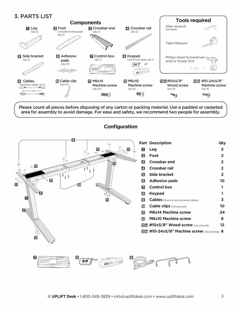
Part Description Qty
Leg 2
Foot 2
Crossbar end 2
Crossbar rail 2
Side bracket 2
Adhesive pads 10
Control box 1
Keypad 1
Cables (Power & two connector cables) 3
Cable clips (not pictured) 10
M6x14 Machine screw 24
M6x10 Machine screw 8
#10x5/8’’ Wood screw (not pictured) 12
#10-24x5/8’’ Machine screw (not pictured) 8
or
Please count all pieces before disposing of any carton or packing material. Use a padded or carpeted area for assembly to avoid damage. For ease and safety, we recommend two people for assembly.
Connector cables, qty 2
Power cable, qty 1
Leg(qty 2)
Control box (qty 1)
Adhesivepads (qty 10)
Cables M6x10 Machine screw (qty 8)
#10x5/8’’ Wood screw (qty 12)
#10-24x5/8’’ Machine screw (qty 8)
Cable clip (qty 10)
Crossbar end (qty 2)
Crossbar rail (qty 2)
Side bracket (qty 2)
M6x14 Machine screw (qty 24)
Keypad (one of two types, qty 1)
or
Philips Head Screwdriver and/or Power Drill
Tape Measure
Allen wrench(included)
Tools requiredComponents1
1
1
2
2
2
3
3
4
4
5
5
5
6
6
7
7
7
8
8
8
9
9
10
10
11
11
12
12
11
11
11
11
11
11 11
11
a
a
b
b
13 13
13
13
Configuration
9
6
3. PARTS LIST
12
Foot(includes leveling padsqty 2)
© UPLIFT Desk • 1-800-349-3839 • [email protected] • www.upliftdesk.com4
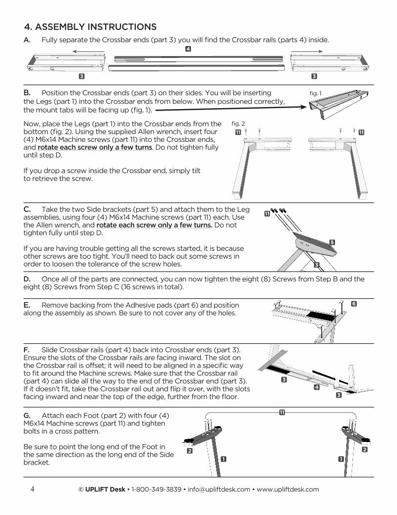
B. Position the Crossbar ends (part 3) on their sides. You will be inserting the Legs (part 1) into the Crossbar ends from below. When positioned correctly, themounttabswillbefacingup(fig.1).
Now, place the Legs (part 1) into the Crossbar ends from the bottom(fig.2).UsingthesuppliedAllenwrench,insertfour (4) M6x14 Machine screws (part 11) into the Crossbar ends, and rotate each screw only a few turns. Do not tighten fully until step D.
If you drop a screw inside the Crossbar end, simply tilt to retrieve the screw.
A. FullyseparatetheCrossbarends(part3)youwillfindtheCrossbarrails(parts4)inside.
C. Take the two Side brackets (part 5) and attach them to the Leg assemblies, using four (4) M6x14 Machine screws (part 11) each. Use the Allen wrench, and rotate each screw only a few turns. Do not tighten fully until step D.
If you are having trouble getting all the screws started, it is because other screws are too tight. You’ll need to back out some screws in order to loosen the tolerance of the screw holes.
D. Once all of the parts are connected, you can now tighten the eight (8) Screws from Step B and the eight (8) Screws from Step C (16 screws in total).
E. Remove backing from the Adhesive pads (part 6) and position along the assembly as shown. Be sure to not cover any of the holes.
F. Slide Crossbar rails (part 4) back into Crossbar ends (part 3). Ensure the slots of the Crossbar rails are facing inward. The slot on theCrossbarrailisoffset;itwillneedtobealignedinaspecificway tofitaroundtheMachinescrews.MakesurethattheCrossbarrail(part 4) can slide all the way to the end of the Crossbar end (part 3). Ifitdoesn’tfit,taketheCrossbarrailoutandflipitover,withtheslotsfacinginwardandnearthetopoftheedge,furtherfromthefloor.
fig.1
fig.2
3
3
3
3
3
4
4
11
11
11
5
6
4. ASSEMBLY INSTRUCTIONS
G. Attach each Foot (part 2) with four (4) M6x14 Machine screws (part 11) and tighten bolts in a cross pattern.
Be sure to point the long end of the Foot in the same direction as the long end of the Side bracket.
11
22
11
© UPLIFT Desk • 1-800-349-3839 • [email protected] • www.upliftdesk.com 5
12
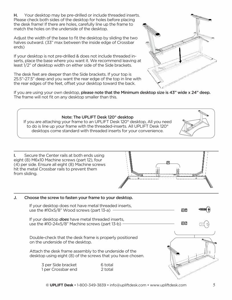
H. Your desktop may be pre-drilled or include threaded inserts. Please check both sides of the desktop for holes before placing the desk frame! If there are holes, carefully line up the frame to match the holes on the underside of the desktop.
Adjustthewidthofthebasetofitthedesktopbyslidingthetwohalves outward. (33’’ max between the inside edge of Crossbar ends)
If your desktop is not pre-drilled & does not include threaded in-serts, place the base where you want it. We recommend leaving at least 1/2” of desktop width on either side of the Side brackets.
The desk feet are deeper than the Side brackets. If your top is 25.5”-27.5” deep and you want the rear edge of the top in line with the rear edges of the feet, offset your desktop toward the back.
If you are using your own desktop, please note that the Minimum desktop size is 43’’ wide x 24’’ deep. Theframewillnotfitonanydesktopsmallerthanthis.
I. Secure the Center rails at both ends using eight (8) M6x10 Machine screws (part 12), four (4) per side. Ensure all eight (8) Machine screws hit the metal Crossbar rails to prevent them from sliding.
Double-check that the desk frame is properly positioned on the underside of the desktop.
Attach the desk frame assembly to the underside of the desktop using eight (8) of the screws that you have chosen.
J. Choose the screw to fasten your frame to your desktop.
If your desktop does not have metal threaded inserts, use the #10x5/8’’ Wood screws (part 13-a)
If your desktop does have metal threaded inserts, use the #10-24x5/8’’ Machine screws (part 13-b)
3 per Side bracket 6 total1 per Crossbar end 2 total
a
b
13
13
Note: The UPLIFT Desk 120° desktop If you are attaching your frame to an UPLIFT Desk 120° desktop, All you need
to do is line up your frame with the threaded-inserts. All UPLIFT Desk 120° desktops come standard with threaded inserts for your convenience.
© UPLIFT Desk • 1-800-349-3839 • [email protected] • www.upliftdesk.com6
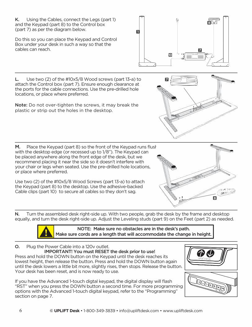
K. Using the Cables, connect the Legs (part 1) and the Keypad (part 8) to the Control box (part 7) as per the diagram below.
Do this so you can place the Keypad and Control Box under your desk in such a way so that the cables can reach.
L. Use two (2) of the #10x5/8 Wood screws (part 13-a) to attach the Control box (part 7). Ensure enough clearance at the ports for the cable connections. Use the pre-drilled hole locations, or place where preferred.
Note: Do not over-tighten the screws, it may break the plastic or strip out the holes in the desktop.
M. PlacetheKeypad(part8)sothefrontoftheKeypadrunsflush with the desktop edge (or recessed up to 1/8”). The Keypad can be placed anywhere along the front edge of the desk, but we recommend placing it near the side so it doesn’t interfere with your chair or legs when seated. Use the pre-drilled hole locations, or place where preferred.
Use two (2) of the #10x5/8 Wood Screws (part 13-a) to attach the Keypad (part 8) to the desktop. Use the adhesive-backed Cable clips (part 10) to secure all cables so they don’t sag.
N. Turn the assembled desk right-side up. With two people, grab the desk by the frame and desktop equally, and turn the desk right-side up. Adjust the Leveling studs (part 9) on the Feet (part 2) as needed.
NOTE: Make sure no obstacles are in the desk’s path. Make sure cords are a length that will accommodate the change in height.!
1
7
7
8
10
8
O. Plug the Power Cable into a 120v outlet. IMPORTANT! You must RESET the desk prior to use!
Press and hold the DOWN button on the Keypad until the desk reaches its lowest height, then release the button. Press and hold the DOWN button again until the desk lowers a little bit more, slightly rises, then stops. Release the button. Your desk has been reset, and is now ready to use.
IfyouhavetheAdvanced1-touchdigtalkeypad,thedigitaldisplaywillflash“RST” when you press the DOWN button a second time. For more programming options with the Advanced 1-touch digital keypad, refer to the “Programming” section on page 7.
© UPLIFT Desk • 1-800-349-3839 • [email protected] • www.upliftdesk.com 7
Following desk assembly, adjust the Leveling studs or casters (sold separately) on the feet so that the desk is level and does not shift its position.
When moving the desk, if casters are not installed, use a two-person lift and lift the desk so that it can be moved without dragging. Dragging the desk may cause the frame and screws to pull loose from the desktop.
When moving the desk, DO NOT lift the desk by the desktop alone, or the frame, alone. Support both the frame and the desktop equally. Favoring one over the other can stress the fasteners connecting the desk frame to the desktop. Lower the desk completely and lift the desk by grasping the frame.
Choose a placement for the desk that’s a safe distance from window frames, radiators, furniture, etc., so that people do not get stuck or trapped by the desk.
Check cord clearance, so that they don’t get jammed. Then connect the desk to the 120v outlet and the desk is ready for use.
Do not place any objects underneath the desk that are taller than 20’’.
KEYPAD LOCK
The keypad can be locked to prevent accidental activation or movement of the desk.
To lock: Press and hold “M” button until display changes to “LOC”
To unlock: Press and hold “M” button until display changes to numeric height setting.
NOTE: If a power outage occurs, the program will automatically return to the unlocked setting.
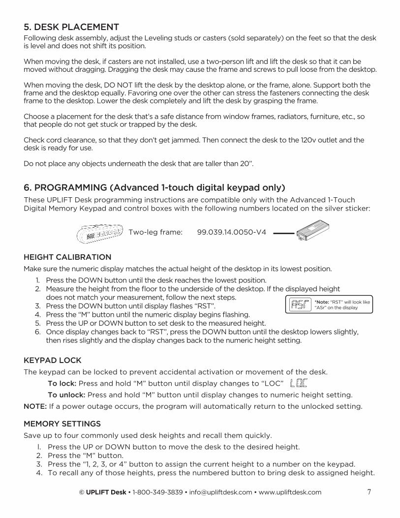
These UPLIFT Desk programming instructions are compatible only with the Advanced 1-Touch Digital Memory Keypad and control boxes with the following numbers located on the silver sticker:
MEMORY SETTINGS
Save up to four commonly used desk heights and recall them quickly.
l. Press the UP or DOWN button to move the desk to the desired height. 2. Press the “M” button. 3. Press the “1, 2, 3, or 4” button to assign the current height to a number on the keypad. 4. To recall any of those heights, press the numbered button to bring desk to assigned height.
6. PROGRAMMING (Advanced 1-touch digital keypad only)
5. DESK PLACEMENT
Two-leg frame: 99.039.14.0050-V4
HEIGHT CALIBRATION
Make sure the numeric display matches the actual height of the desktop in its lowest position.
1. Press the DOWN button until the desk reaches the lowest position. 2. Measuretheheightfromthefloortotheundersideofthedesktop.Ifthedisplayedheight does not match your measurement, follow the next steps. 3. PresstheDOWNbuttonuntildisplayflashes“RST”. 4. Pressthe“M”buttonuntilthenumericdisplaybeginsflashing. 5. Press the UP or DOWN button to set desk to the measured height. 6. Once display changes back to “RST”, press the DOWN button until the desktop lowers slightly, then rises slightly and the display changes back to the numeric height setting.
*Note: “RST” will look like“ASr” on the display
© UPLIFT Desk • 1-800-349-3839 • [email protected] • www.upliftdesk.com8
CONSTANT-TOUCH & ONE-TOUCH
These steps allow the desktop to be set to either One-Touch or Constant-Touch. One-Touch requires only a single touch of the “1, 2, 3, or 4” button to move the desktop to a preset memory location. One-Touch is the default setting. Constant-Touch requires a continuous touch of the “1, 2, 3, or 4” button to move the desktop to a preset memory location.
Change between One-Touch and Constant-Touch:
l. Press the DOWN button until the desk reaches the lowest position. 2. PresstheDOWNbuttonagainuntildisplayflashes“RST”. 3. Press the “1” button until display shows “10.1” (One-Touch) or “10.2” (Constant-Touch) and goes back to “RST”.
Note:While“RST”isstillflashing,youcanpressthe“1”buttonasmanytimesasyou’dlike to toggle between the two settings.
4. Press the DOWN button until the desktop lowers slightly, then rises slightly and the display changes back to the numeric height setting.
MINIMUM & MAXIMUM HEIGHT SETTINGS
The desk frame ships defaulted to its minimum and maximum height limits. These steps allow the upper and lower limits to be adjusted to your preference.
Note: If memory settings were previously set outside of the new minimum and maximum height settings, they will default to the new minimum and maximum settings. To set new minimum and maximumheightsettingsoutsideofthecurrentsettings,youwillneedtofirstremovethecurrentminimum and maximum settings.
DISPLAY UNITS
Change the numeric display to show heights in either inches or centimeters.
l. Press the DOWN button until the desk reaches the lowest position. Release button. 2. PresstheDOWNbuttonuntildisplayflashes“RST”. 3. Press the “2” button until display shows “10.3” (centimeters) or “10.4” (inches) and goes back to “RST”.
Note:While“RST”isstillflashing,youcanpressthe“2”buttonasmanytimesasyou’dlike to toggle between the two settings.
4. Press the DOWN button until the desktop lowers slightly, then rises slightly and the display changes back to the numeric height setting.
6. PROGRAMMING (continued):
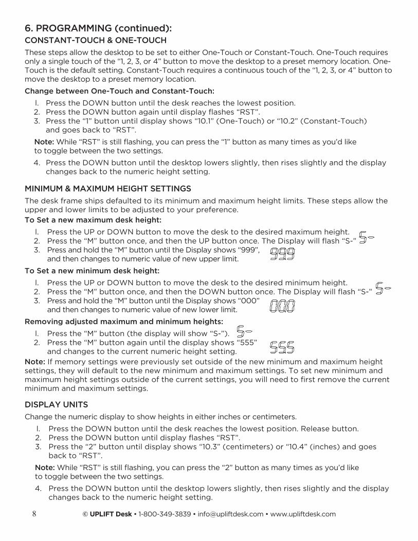
To Set a new maximum desk height:
l. Press the UP or DOWN button to move the desk to the desired maximum height. 2. Pressthe“M”buttononce,andthentheUPbuttononce.TheDisplaywillflash“S-” 3. Press and hold the “M” button until the Display shows “999”, and then changes to numeric value of new upper limit.
To Set a new minimum desk height:
l. Press the UP or DOWN button to move the desk to the desired minimum height. 2. Pressthe“M”buttononce,andthentheDOWNbuttononce.TheDisplaywillflash“S-” 3. Press and hold the “M” button until the Display shows “000” and then changes to numeric value of new lower limit.
Removing adjusted maximum and minimum heights:
l. Press the “M” button (the display will show “S-”). 2. Press the “M” button again until the display shows “555” and changes to the current numeric height setting.
© UPLIFT Desk • 1-800-349-3839 • [email protected] • www.upliftdesk.com 9
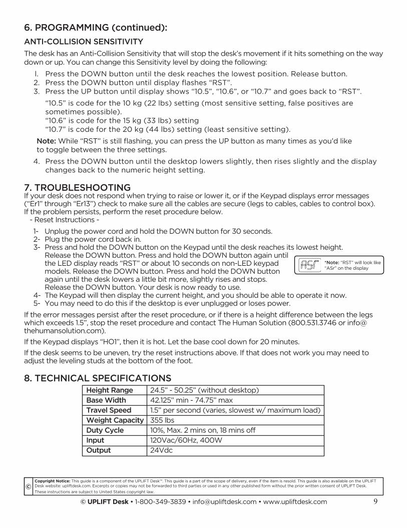
Height Range 24.5” - 50.25” (without desktop)
Base Width 42.125” min - 74.75” max
Travel Speed 1.5” per second (varies, slowest w/ maximum load)
Weight Capacity 355 lbs
Duty Cycle 10%, Max. 2 mins on, 18 mins off
Input 120Vac/60Hz, 400W
Output 24Vdc
If your desk does not respond when trying to raise or lower it, or if the Keypad displays error messages (“Er1” through “Er13”) check to make sure all the cables are secure (legs to cables, cables to control box). If the problem persists, perform the reset procedure below. - Reset Instructions -
1- Unplug the power cord and hold the DOWN button for 30 seconds.2- Plug the power cord back in.3- Press and hold the DOWN button on the Keypad until the desk reaches its lowest height.
Release the DOWN button. Press and hold the DOWN button again until the LED display reads “RST” or about 10 seconds on non-LED keypad models. Release the DOWN button. Press and hold the DOWN button again until the desk lowers a little bit more, slightly rises and stops. Release the DOWN button. Your desk is now ready to use.
4- The Keypad will then display the current height, and you should be able to operate it now.5- You may need to do this if the desktop is ever unplugged or loses power.
If the error messages persist after the reset procedure, or if there is a height difference between the legs which exceeds 1.5’’, stop the reset procedure and contact The Human Solution (800.531.3746 or [email protected]).
If the Keypad displays “HO1”, then it is hot. Let the base cool down for 20 minutes.
If the desk seems to be uneven, try the reset instructions above. If that does not work you may need to adjust the leveling studs at the bottom of the foot.
*Note: “RST” will look like“ASr” on the display
6. PROGRAMMING (continued):
7. TROUBLESHOOTING
8. TECHNICAL SPECIFICATIONS
Copyright Notice: This guide is a component of the UPLIFT Desk™. This guide is a part of the scope of delivery, even if the item is resold. This guide is also available on the UPLIFT Desk website: upliftdesk.com. Excerpts or copies may not be forwarded to third parties or used in any other published form without the prior written consent of UPLIFT Desk.
These instructions are subject to United States copyright law.©
ANTI-COLLISION SENSITIVITY
The desk has an Anti-Collision Sensitivity that will stop the desk’s movement if it hits something on the way down or up. You can change this Sensitivity level by doing the following:
l. Press the DOWN button until the desk reaches the lowest position. Release button. 2. PresstheDOWNbuttonuntildisplayflashes“RST”. 3. Press the UP button until display shows “10.5”, “10.6”, or “10.7” and goes back to “RST”.
“10.5” is code for the 10 kg (22 lbs) setting (most sensitive setting, false positives are sometimes possible). “10.6” is code for the 15 kg (33 lbs) setting “10.7” is code for the 20 kg (44 lbs) setting (least sensitive setting).
Note:While“RST”isstillflashing,youcanpresstheUPbuttonasmanytimesasyou’dlike to toggle between the three settings.
4. Press the DOWN button until the desktop lowers slightly, then rises slightly and the display changes back to the numeric height setting.