european powder metallurgy association Functional ... - EPMA
Upload
nguyenkietCategory
view
215download
0
Powder Metallurgy Association of India
President Shri N. Gopinath
Vice President Shri Aniket Gore Shri Deepak Grover Prof. Narendra Dhokey Shri Rajendra Sethiya General Secretary Dr. Deep Prakash
Treasurer Dr. Murli Gopal Krishnamoorty
Joint Secretary Shri Sidharth Singhal Shri Deepak Pattanayak
Office Bearers
Price Rs. 500/-
Trans. PMAI.Vol.43.No.2, 2017 features selected papers from the International Conference PM-17, held at Hotel Pride Plaza, New Delhi. The first paper is on the powder characterization dealing with particle size, size distribution and shape and how these are useful in optimizing the metal injection molding process. This is followed by an article on the effect of particle size and compaction pressure on dimensional shrinkage of sintered iron
powder compacts. Microstructural analysis of Ag-Bi-Cu-Sb-Sn alloys prepared by ball milling of elemental powders followed by spark plasma sintering is the subject matter of next paper. This is followed by an article on vacuum sintering as a cost effective sintering process to make high strength low alloy steel without the addition of expensive nickel.Next paper is on the sintering process parameters such as temperature, heating rate, cooling rate and atmosphere on the final density of injection molded stainless steel powders. The properties of immiscible Cu-20wt.%-Mo alloy prepared by high energy ball milling of elemental powders followed by cold isostatic pressing and sintering is dealt with in the next paper. This is followed by an article on the processing of high strength nickel base super alloy and correlating their structure and properties. Next paper is on the development of cathode material based on Gadolinium Cobalt ferrite for intermediate temperature solid oxide fuel cell. To protect Niobium alloy from oxidation, ultrahigh temperature coatings of Zirconium boride and Zirconium boride-Silicon carbides, processed by reaction plasma sintering have been considered in the next article.
W-Cu functionally graded samples with seven layered structures have been fabricated by spark plasma sintering and these materials are significant in the development of fusion reactors. Next paper is on the finite element analysis of various materials for carrier boats used in the sintering operation of Uranium oxide pellets for nuclear fuel fabrication and resulted in the identification of the best suited material. This is followed by a paper on the preparation of Copper-Graphite-SiC composites from elemental powders and their deformation behavior.The concluding paper is reviewing the role of MoS₂ and CaF₂ solid lubricants including the nano- lubricants on the composite cutting tools in the dry machining technology.
P. Ramakrishnan
EditorialChief EditorProf. Ramakrishnan P.
Editorial Advisory Board Dr. Ashok S.Mr. Chandrachud N.L.Dr. Rama Mohan T. R.
Editorial BoardDr. Appa Rao G. Dr. Bhargava ParagDr. Dabhade VikramDr. Deep PrakashDr. Dhokey N.B.Dr. Kumar Y.V.S.Dr. Malobika KaranjaiDr. Murli Gopal K.Dr. Panigrahi B.B.Dr. Sastry I.S.R.Dr. Tarasankar Mahata
Published by :Powder Metallurgy Association of India (PMAI)1002, B-Wing, Kingston, High Street, Hiranandani Complex,Powai, Mumbai - 4000076.Tel. : +9122 25704588E-mail : [email protected] the Powder Metallurgy Association of India nor the editor assumes responsibility of opinions expressed by the authors of the papers published in this transaction.
TRANSACTIONS OFPOWDER METALLURGY ASSOCIATION OF INDIA
Vol. 43 No.2, December 2017
CONTENTS
1 ParticleCharacterizationanditsRelevanceinPowderMetallurgy 1-4 Tamal Mukherjee Malvern Aimil Instruments Pvt Ltd., New Delhi, India
2 EffectofParticleSizeandProcessParametersonDimensionalShrinkage 5-9 ofSinteredCompact C. R. Patil, V. T. Thavale, N. B. Dhokey Department of Metallurgy and Materials Science,College of Engineering Pune, India
3 APreliminaryMicrostructuralAnalysisofnewAg-Bi-Cu-Sb-SnBased 10-13 Multi-componentAlloys. Rahul Ravi, Srinivasa R Bakshi Dept. Met. &Mat. Engg, IIT Madras, Chennai, India
4 VacuumSinteringasaCostEffectiveSinteringProcess 14-18 S. R Sundaram, U.Nagarajan, D. Jayaprakash Narayanan Pricol Ltd, Coimbatore, India.
5 TheEffectofSinteringProcessParametersonFinalDensityofSinteredParts 19-25 producedbyusingMetalInjectionMolding(MIM) Praveen Pachauri, Md. Hamiuddin Noida Institute of Engineering and Technology, Greater Noida, AMU, Aligarh, India
6 PropertiesofImmiscibleCu-20wt.%MoAlloyPreparedbyHighEnergyBall 26-32 MillingandColdIsostaticPressing P. Senguptaa, , M. Debataa and K. Jayasankarb a CSIR – Institute of Minerals and Materials Technology, Bhubaneswar, India b CSIR – National Institute for Interdisciplinary Science and Technology, Thiruvananthapuram, India
7 StructurePropertyCorrelationsinHotIsostaticallyPressedHighStrength 33-41 NickelBaseSuperalloy B. Sreenu, Subhradeep Chatterjee, G. Appa Rao, Defence Metallurgical Research Laboratory, Dept. Mat. Sci. & Met. Engg, IIT, Hyderabad, India
8 DevelopmentofNovelCathodeMaterialforIT-SOFC 42-46 A. Ahuja, M. Gautam, J. Sharma, AmitSinha, A. Venkatasubramanian, P. K. Sinha, School of Energy and Environment, Thapar University, Patiala, BARC, Vashi Complex, Navi Mumbai, India
9 SynthesisofUltra-HighTemperatureCeramicCoatingonNiobiumAlloyby 47-54 ReactiveSparkPlasmaSintering Manoj Hajare, N. S. Karthiselva, T. Venkateswaran, Srinivasa R. Bakshi Dept. Met. &Mat. Engg, IIT Madras, Chennai, VSSC, Thiruvananthapuramm, India.
10 DevelopmentofW–CufunctionallygradedmaterialbySparkPlasmaSintering 55-61 Processforplasmafacingcomponentapplication Rajat Gupta, Rohit Kumar, Anil Chaubey 1, ShaileshKanpara 2, Sameer Khirwadkar 2, Bhagyadhar Bhoi 1, CSIR- Institute of Minerals and Materials Technology, Bhubaneshwar, India 2 Institute for Plasma Research,Gujarat, India
11 FiniteElementBasedComparisonofVariousMaterialsforChargeCarrierBoats 62-69 usedinSinteringOperationofNuclearFuelFabrication Sumit Raghuvanshi, U.K. Arora, A.C. Wali, G. Kalyanakrishnan Nuclear Fuel Complex, Department of Atomic Energy, Hyderabad, India
12 DeformationBehaviourStudyOfCu-Graphite-SiCMetalMatrixComposite 70-77 PreparedByPowderMetallurgy Biswajit Mishra 1, Debasis Chaira 1, Rajib Saha 2, 1 NIT Rourkela, 2 Tata Steel, Jamshedpur, India
13 EffectofMoS2andCaF2SolidLubricantsonMechanicalandTribological 78-86 CharacteristicsofMetalandCeramicComposites:AReview Sri Ram Vikas. K, N. Raghu Ram, Ch. Kishore Reddy, K. Sivaji Babu Department of Mechanical Engineering, Prasad V. Potluri Siddhartha Institute of Technology, JNTUK, Vijayawada, Andhra Pradesh, India.
TRANSACTIONS OF PMAI, VOL. 43 (2), DECEMBER 2017 1
PARTICLE CHARACTERIZATION AND ITS RELEVANCE IN POWDER METALLURGY
Tamal Mukherjee
Malvern Aimil Instruments Pvt Ltd., New Delhi, India
IntroductionThe manufacture of complex shaped metal parts by Metal Injection Moulding (MIM) and Additive Manufacturing (AM) is a growing industry. The shape and size of metal powders play an important role in determining process efficiency and properties of the final MIM and AM components. Spherical powder particles are typically favoured by MIM manufacturers looking to achieve best tolerances and properties in final components. Therefore, it is important to monitor atomized powder to ensure that particles of the desired shape and size are produced. The metal injection moulding process (MIM) is used in the manufacture of complex-shaped, high volume, low weight parts where intricate detail may be required along with accurate tolerance control. The MIM process involves four crucial steps as following. 1. Atomization of molten metal to form metal
powders which are further processed by sieving and/or gas classification to obtain the appropriate particle size distribution. The powder is then mixed with thermoplastic binders to form pellets of feedstock ready for step 2.
2. Feedstock is injected into a mould or die to form ‘green’ metal injection moulded parts.
3. The binder is removed from the ‘green’ part by solvent and/or thermal processes to leave a ‘brown’ metal part.
4. The ‘brown’ part undergoes a sintering process in a high temperature furnace where the metal particles fuse together.
Particle size is important during this stage, but so is particle shape since spherical powders will have a higher packing density. This means more touching surfaces, faster sintering times and reduced shrinkage resulting in better dimensional control. Therefore, the size and the shape of the original metal particles produced in step 1 will affect the final product and must be carefully controlled.
This paper describes how atomized powders with similar particle size distributions produced by two different atomizing processes, can have very different shape properties and how such parameters can be assessed using automated image analysis.
Abstract : Particle size and particle size distribution, along with other parameters such as particle shape dictate the efficiency of powder metallurgy process and have a direct influence on the bulk properties of the finished product. Particle size is a defining parameter for metal powders. Atomization is the most commonly used metal powder production technique, but milling is also routinely applied. Both processes are extremely energy intensive so it is vital to monitor operating conditions not only to tailor the size of the particles, but also to minimize energy consumption. Laser diffraction is a well-established technique across particulate processing industry for measuring particle size distribution. The technique is known for its operational simplicity, easy to use and in many cases completely automated. Furthermore, how the particles pack together is a function of particle size, size distribution and indeed shape. Monitoring and controlling particle shape along with size improves the characteristics of metal powders.
Keywords: Particle size, morphology
TRANSACTIONS OF PMAI, VOL. 43 (2), DECEMBER 20172
PARTICLE CHARACTERIZATION AND ITS RELEVANCE IN POWDER METALLURGY
Materials and Methods
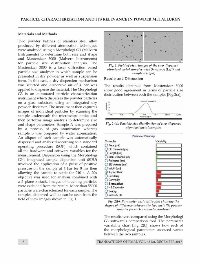
Two powder batches of stainless steel alloy produced by different atomization techniques were analysed using a Morphologi G3 (Malvern Instruments) to determine both size and shape and Mastersizer 3000 (Malvern Instruments) for particle size distribution analysis. The Mastersizer 3000 is a laser diffraction based particle size analyser in which sample can be presented in dry powder as well as suspension form. In this case, a dry dispersion mechanism was selected and dispersive air of 4 bar was applied to disperse the material. The Morphologi G3 is an automated particle characterization instrument which disperses the powder particles on a glass substrate using an integrated dry powder disperser. The instrument then captures images of individual particles by scanning the sample underneath the microscope optics and then performs image analysis to determine size and shape parameters. Sample A was prepared by a process of gas atomization whereas sample B was prepared by water atomization. An aliquot of each sample was automatically dispersed and analysed according to a standard operating procedure (SOP) which contained all the hardware and software variables for the measurement. Dispersion using the Morphologi G3’s integrated sample dispersion unit (SDU) involved the application of a pulse of positive pressure on the sample at 4 bar for 8 ms then allowing the sample to settle for 240 s. A 20x objective was used for analysis combined with a 3 plane z-stack. Images of touching particles were excluded from the results. More than 55000 particles were characterized for each sample. The samples dispersed well as can be seen from the field of view images shown in Fig. 1.
Fig. 1: Field of view images of the two dispersed atomized metal samples with Sample A (Left) and
Sample B (right)
Fig. 2 (a): Particle size distribution of two dispersed atomized metal samples
Fig. 2(b): Parameter variability plot showing the degree of difference between the two metallic powder
samples for each parameter analysed
The results were compared using the Morphologi G3 software’s comparison tool. The parameter variability chart [Fig. 2(b)] shows how each of the morphological parameters assessed varies between the two samples.
Results and Discussion
The results obtained from Mastersizer 3000 show good agreement in terms of particle size distribution between both the samples [Fig.2(a)].
TRANSACTIONS OF PMAI, VOL. 43 (2), DECEMBER 2017 3
PARTICLE CHARACTERIZATION AND ITS RELEVANCE IN POWDER METALLURGY
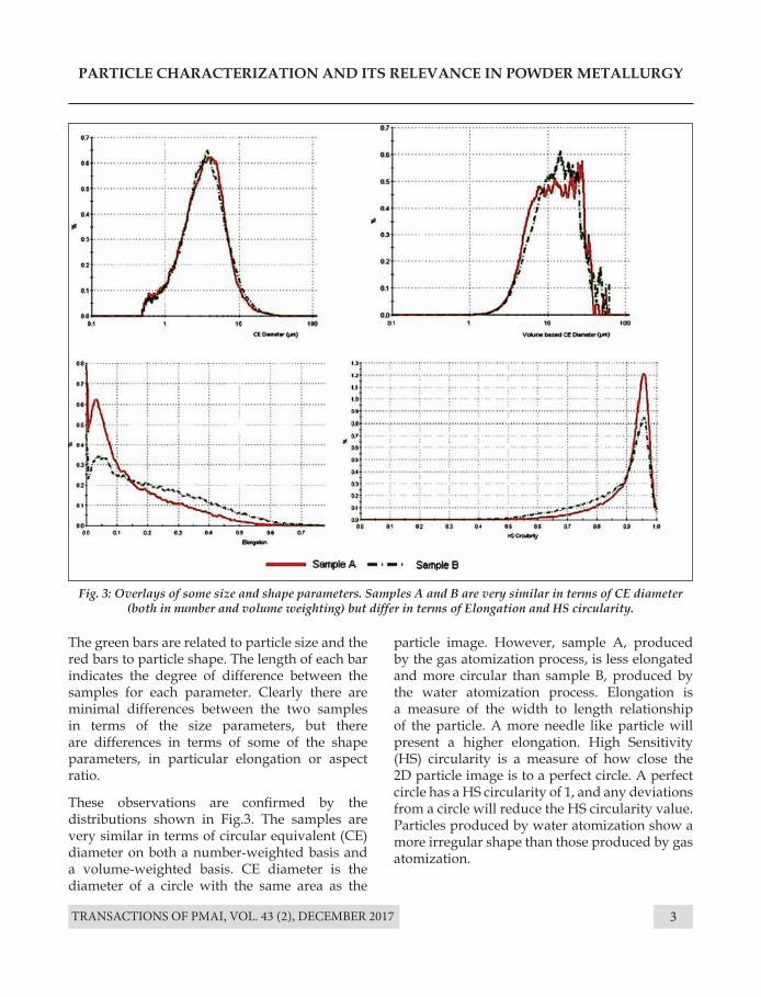
Fig. 3: Overlays of some size and shape parameters. Samples A and B are very similar in terms of CE diameter (both in number and volume weighting) but differ in terms of Elongation and HS circularity.
The green bars are related to particle size and the red bars to particle shape. The length of each bar indicates the degree of difference between the samples for each parameter. Clearly there are minimal differences between the two samples in terms of the size parameters, but there are differences in terms of some of the shape parameters, in particular elongation or aspect ratio.
These observations are confirmed by the distributions shown in Fig.3. The samples are very similar in terms of circular equivalent (CE) diameter on both a number-weighted basis and a volume-weighted basis. CE diameter is the diameter of a circle with the same area as the
particle image. However, sample A, produced by the gas atomization process, is less elongated and more circular than sample B, produced by the water atomization process. Elongation is a measure of the width to length relationship of the particle. A more needle like particle will present a higher elongation. High Sensitivity (HS) circularity is a measure of how close the 2D particle image is to a perfect circle. A perfect circle has a HS circularity of 1, and any deviations from a circle will reduce the HS circularity value. Particles produced by water atomization show a more irregular shape than those produced by gas atomization.
TRANSACTIONS OF PMAI, VOL. 43 (2), DECEMBER 20174
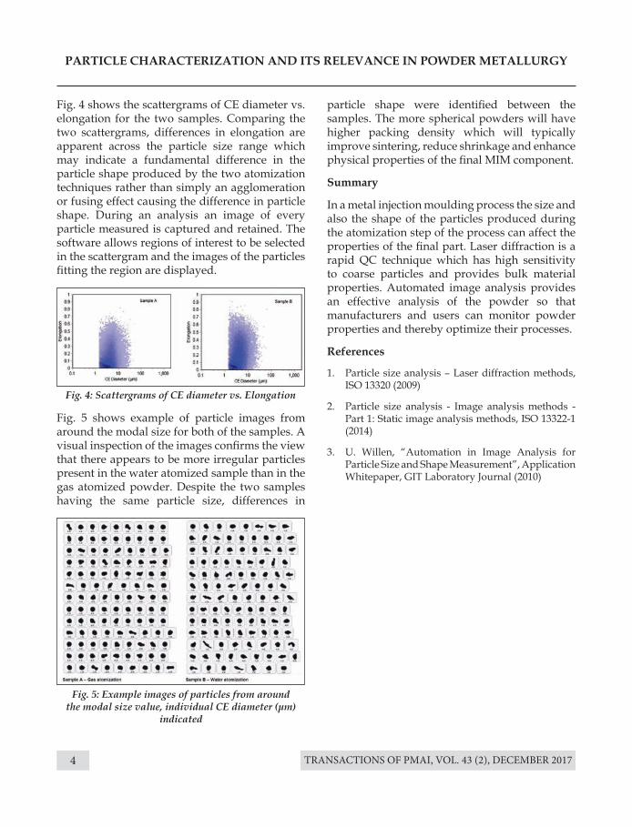
Fig. 4: Scattergrams of CE diameter vs. Elongation
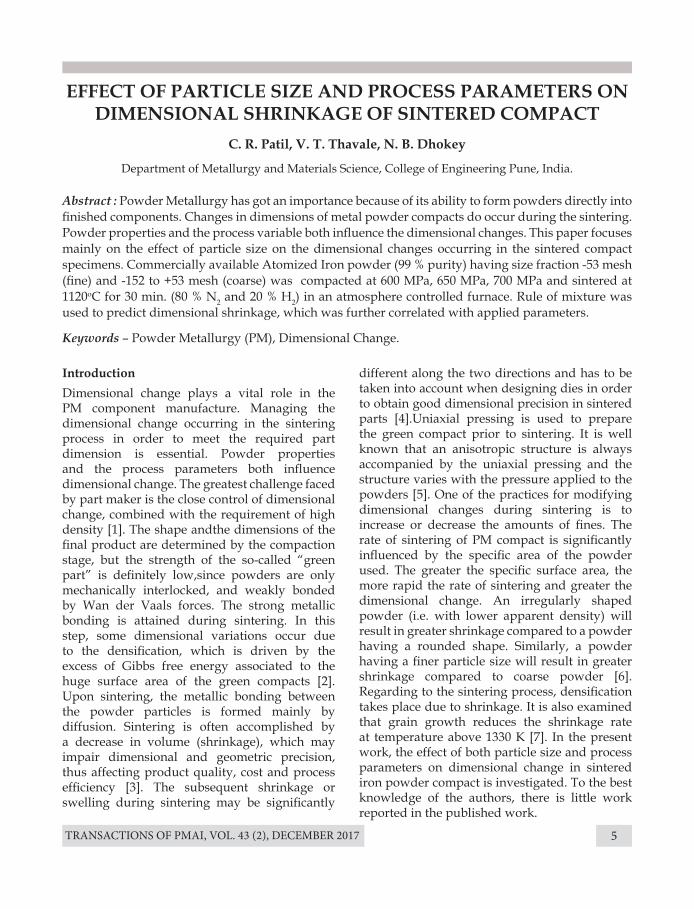
Fig. 5: Example images of particles from around the modal size value, individual CE diameter (μm)
indicated
PARTICLE CHARACTERIZATION AND ITS RELEVANCE IN POWDER METALLURGY
Fig. 4 shows the scattergrams of CE diameter vs. elongation for the two samples. Comparing the two scattergrams, differences in elongation are apparent across the particle size range which may indicate a fundamental difference in the particle shape produced by the two atomization techniques rather than simply an agglomeration or fusing effect causing the difference in particle shape. During an analysis an image of every particle measured is captured and retained. The software allows regions of interest to be selected in the scattergram and the images of the particles fitting the region are displayed.
Fig. 5 shows example of particle images from around the modal size for both of the samples. A visual inspection of the images confirms the view that there appears to be more irregular particles present in the water atomized sample than in the gas atomized powder. Despite the two samples having the same particle size, differences in
particle shape were identified between the samples. The more spherical powders will have higher packing density which will typically improve sintering, reduce shrinkage and enhance physical properties of the final MIM component.
Summary
In a metal injection moulding process the size and also the shape of the particles produced during the atomization step of the process can affect the properties of the final part. Laser diffraction is a rapid QC technique which has high sensitivity to coarse particles and provides bulk material properties. Automated image analysis provides an effective analysis of the powder so that manufacturers and users can monitor powder properties and thereby optimize their processes.
References
1. Particle size analysis – Laser diffraction methods, ISO 13320 (2009)
2. Particle size analysis - Image analysis methods - Part 1: Static image analysis methods, ISO 13322-1 (2014)
3. U. Willen, “Automation in Image Analysis for Particle Size and Shape Measurement”, Application Whitepaper, GIT Laboratory Journal (2010)
TRANSACTIONS OF PMAI, VOL. 43 (2), DECEMBER 2017 5
EFFECT OF PARTICLE SIZE AND PROCESS PARAMETERS ON DIMENSIONAL SHRINKAGE OF SINTERED COMPACT
C. R. Patil, V. T. Thavale, N. B. Dhokey
Department of Metallurgy and Materials Science, College of Engineering Pune, India.
IntroductionDimensional change plays a vital role in the PM component manufacture. Managing the dimensional change occurring in the sintering process in order to meet the required part dimension is essential. Powder properties and the process parameters both influence dimensional change. The greatest challenge faced by part maker is the close control of dimensional change, combined with the requirement of high density [1]. The shape andthe dimensions of the final product are determined by the compaction stage, but the strength of the so-called “green part” is definitely low,since powders are only mechanically interlocked, and weakly bonded by Wan der Vaals forces. The strong metallic bonding is attained during sintering. In this step, some dimensional variations occur due to the densification, which is driven by the excess of Gibbs free energy associated to the huge surface area of the green compacts [2]. Upon sintering, the metallic bonding between the powder particles is formed mainly by diffusion. Sintering is often accomplished by a decrease in volume (shrinkage), which may impair dimensional and geometric precision, thus affecting product quality, cost and process efficiency [3]. The subsequent shrinkage or swelling during sintering may be significantly
Abstract : Powder Metallurgy has got an importance because of its ability to form powders directly into finished components. Changes in dimensions of metal powder compacts do occur during the sintering. Powder properties and the process variable both influence the dimensional changes. This paper focuses mainly on the effect of particle size on the dimensional changes occurring in the sintered compact specimens. Commercially available Atomized Iron powder (99 % purity) having size fraction -53 mesh (fine) and -152 to +53 mesh (coarse) was compacted at 600 MPa, 650 MPa, 700 MPa and sintered at 1120oC for 30 min. (80 % N2 and 20 % H2) in an atmosphere controlled furnace. Rule of mixture was used to predict dimensional shrinkage, which was further correlated with applied parameters.
Keywords – Powder Metallurgy (PM), Dimensional Change.
different along the two directions and has to be taken into account when designing dies in order to obtain good dimensional precision in sintered parts [4].Uniaxial pressing is used to prepare the green compact prior to sintering. It is well known that an anisotropic structure is always accompanied by the uniaxial pressing and the structure varies with the pressure applied to the powders [5]. One of the practices for modifying dimensional changes during sintering is to increase or decrease the amounts of fines. The rate of sintering of PM compact is significantly influenced by the specific area of the powder used. The greater the specific surface area, the more rapid the rate of sintering and greater the dimensional change. An irregularly shaped powder (i.e. with lower apparent density) will result in greater shrinkage compared to a powder having a rounded shape. Similarly, a powder having a finer particle size will result in greater shrinkage compared to coarse powder [6]. Regarding to the sintering process, densification takes place due to shrinkage. It is also examined that grain growth reduces the shrinkage rate at temperature above 1330 K [7]. In the present work, the effect of both particle size and process parameters on dimensional change in sintered iron powder compact is investigated. To the best knowledge of the authors, there is little work reported in the published work.
TRANSACTIONS OF PMAI, VOL. 43 (2), DECEMBER 20176
EFFECT OF PARTICLE SIZE AND PROCESS PARAMETERS ON DIMENSIONAL SHRINKAGE OF SINTERED COMPACT
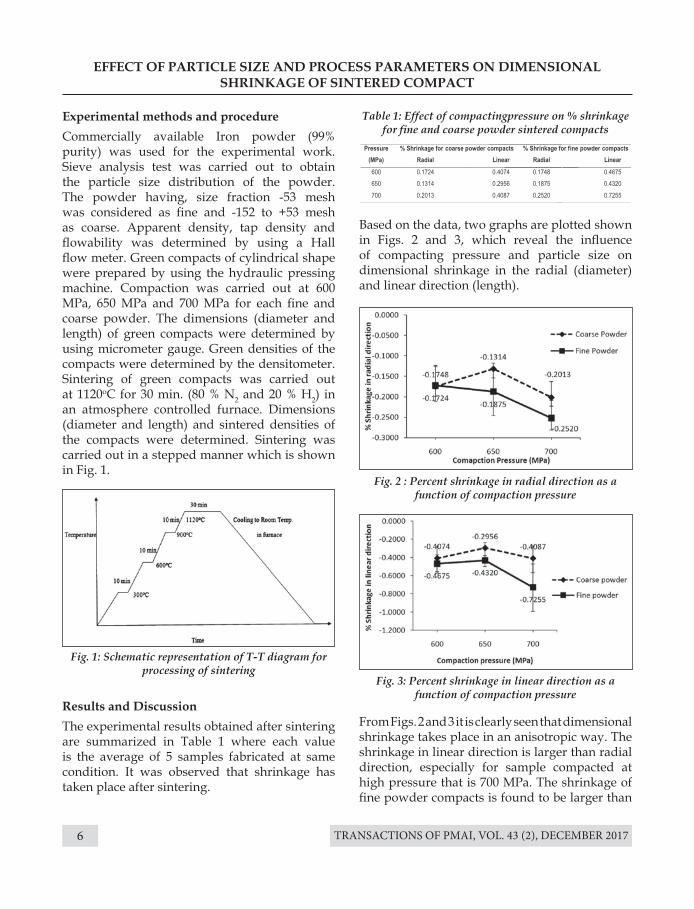
Experimental methods and procedureCommercially available Iron powder (99% purity) was used for the experimental work. Sieve analysis test was carried out to obtain the particle size distribution of the powder. The powder having, size fraction -53 mesh was considered as fine and -152 to +53 mesh as coarse. Apparent density, tap density and flowability was determined by using a Hall flow meter. Green compacts of cylindrical shape were prepared by using the hydraulic pressing machine. Compaction was carried out at 600 MPa, 650 MPa and 700 MPa for each fine and coarse powder. The dimensions (diameter and length) of green compacts were determined by using micrometer gauge. Green densities of the compacts were determined by the densitometer. Sintering of green compacts was carried out at 1120oC for 30 min. (80 % N2 and 20 % H2) in an atmosphere controlled furnace. Dimensions (diameter and length) and sintered densities of the compacts were determined. Sintering was carried out in a stepped manner which is shown in Fig. 1.
Results and DiscussionThe experimental results obtained after sintering are summarized in Table 1 where each value is the average of 5 samples fabricated at same condition. It was observed that shrinkage has taken place after sintering.
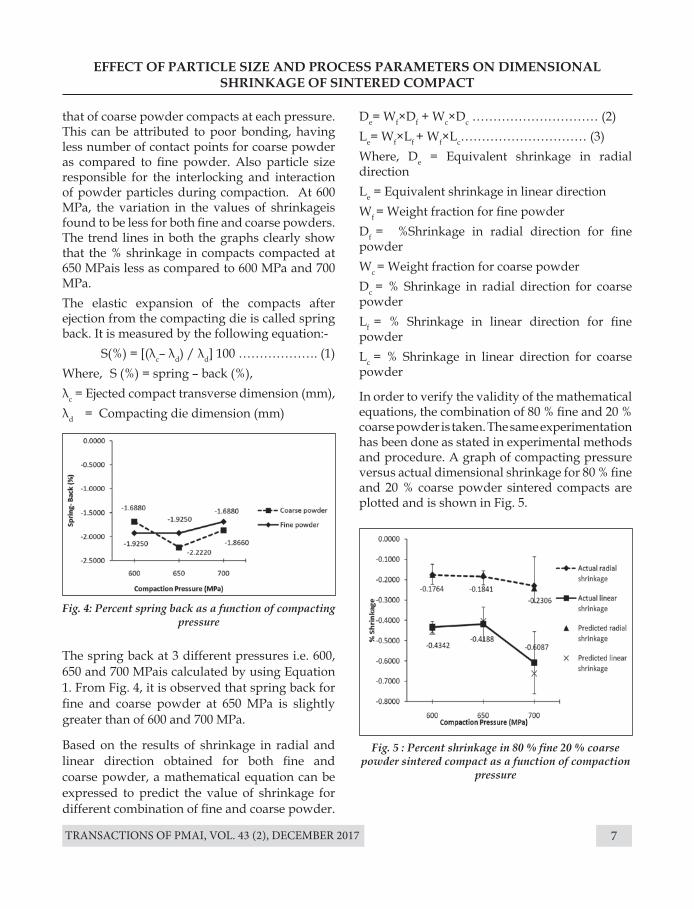
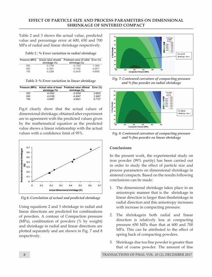
Based on the data, two graphs are plotted shown in Figs. 2 and 3, which reveal the influence of compacting pressure and particle size on dimensional shrinkage in the radial (diameter) and linear direction (length).
From Figs. 2 and 3 it is clearly seen that dimensional shrinkage takes place in an anisotropic way. The shrinkage in linear direction is larger than radial direction, especially for sample compacted at high pressure that is 700 MPa. The shrinkage of fine powder compacts is found to be larger than
Fig. 1: Schematic representation of T-T diagram for processing of sintering
Fig. 2 : Percent shrinkage in radial direction as a function of compaction pressure
Fig. 3: Percent shrinkage in linear direction as a function of compaction pressure
Table 1: Effect of compactingpressure on % shrinkage for fine and coarse powder sintered compacts
TRANSACTIONS OF PMAI, VOL. 43 (2), DECEMBER 2017 7
EFFECT OF PARTICLE SIZE AND PROCESS PARAMETERS ON DIMENSIONAL SHRINKAGE OF SINTERED COMPACT
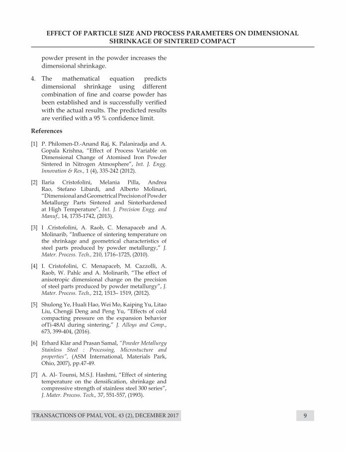
The spring back at 3 different pressures i.e. 600, 650 and 700 MPais calculated by using Equation 1. From Fig. 4, it is observed that spring back for fine and coarse powder at 650 MPa is slightly greater than of 600 and 700 MPa.
Based on the results of shrinkage in radial and linear direction obtained for both fine and coarse powder, a mathematical equation can be expressed to predict the value of shrinkage for different combination of fine and coarse powder.
Fig. 4: Percent spring back as a function of compacting pressure
Fig. 5 : Percent shrinkage in 80 % fine 20 % coarse powder sintered compact as a function of compaction
pressure
that of coarse powder compacts at each pressure. This can be attributed to poor bonding, having less number of contact points for coarse powder as compared to fine powder. Also particle size responsible for the interlocking and interaction of powder particles during compaction. At 600 MPa, the variation in the values of shrinkageis found to be less for both fine and coarse powders. The trend lines in both the graphs clearly show that the % shrinkage in compacts compacted at 650 MPais less as compared to 600 MPa and 700 MPa. The elastic expansion of the compacts after ejection from the compacting die is called spring back. It is measured by the following equation:-
S(%) = [(λc– λd) / λd] 100 ………………. (1)Where, S (%) = spring – back (%), λc = Ejected compact transverse dimension (mm), λd = Compacting die dimension (mm)
De= Wf×Df + Wc×Dc ………………………… (2)Le= Wf×Lf + Wf×Lc………………………… (3)Where, De = Equivalent shrinkage in radial directionLe = Equivalent shrinkage in linear directionWf = Weight fraction for fine powderDf = %Shrinkage in radial direction for fine powderWc = Weight fraction for coarse powderDc = % Shrinkage in radial direction for coarse powder Lf = % Shrinkage in linear direction for fine powderLc = % Shrinkage in linear direction for coarse powder
In order to verify the validity of the mathematical equations, the combination of 80 % fine and 20 % coarse powder is taken. The same experimentation has been done as stated in experimental methods and procedure. A graph of compacting pressure versus actual dimensional shrinkage for 80 % fine and 20 % coarse powder sintered compacts are plotted and is shown in Fig. 5.
TRANSACTIONS OF PMAI, VOL. 43 (2), DECEMBER 20178
Table 2 : % Error variation in radial shrinkage
Fig 6: Correlation of actual and predicted shrinkage
Fig. 7: Contoured curvature of compacting pressure and % fine powder on radial shrinkage
Fig. 8: Contoured curvature of compacting pressure and % fine powder on linear shrinkage
Table 3: % Error variation in linear shrinkage
EFFECT OF PARTICLE SIZE AND PROCESS PARAMETERS ON DIMENSIONAL SHRINKAGE OF SINTERED COMPACT
Fig.6 clearly show that the actual values of dimensional shrinkage, obtained after experiment are in agreement with the predicted values given by the mathematical equation as the predicted value shows a linear relationship with the actual values with a confidence limit of 95%.
Conclusions
In the present work, the experimental study on iron powder (99% purity) has been carried out in order to study the effect of particle size and process parameters on dimensional shrinkage in sintered compacts. Based on the results following conclusions can be made:
1. The dimensional shrinkage takes place in an anisotropic manner that is the shrinkage in linear direction is larger than theshrinkage in radial direction and this anisotropy increases with increase in compacting pressure.
2. The shrinkagein both radial and linear direction is relatively less at compacting pressure 650 MPa than that at 600 and 700 MPa. This can be attributed to the effect of spring back of compacting powders.
3. Shrinkage due toa fine powder is greater than that of coarse powder. The amount of fine
Using equations 2 and 3 shrinkage in radial and linear directions are predicted for combinations of powders. A contour of Compaction pressure (MPa), combination of powders (% by weight) and shrinkage in radial and linear directions are plotted separately and are shown in Fig. 7 and 8 respectively.
Table 2 and 3 shows the actual value, predicted value and percentage error at 600, 650 and 700 MPa of radial and linear shrinkage respectively.
TRANSACTIONS OF PMAI, VOL. 43 (2), DECEMBER 2017 9
EFFECT OF PARTICLE SIZE AND PROCESS PARAMETERS ON DIMENSIONAL SHRINKAGE OF SINTERED COMPACT
powder present in the powder increases the dimensional shrinkage.
4. The mathematical equation predicts dimensional shrinkage using different combination of fine and coarse powder has been established and is successfully verified with the actual results. The predicted results are verified with a 95 % confidence limit.
References
[1] P. Philomen-D.-Anand Raj, K. Palaniradja and A. Gopala Krishna, “Effect of Process Variable on Dimensional Change of Atomised Iron Powder Sintered in Nitrogen Atmosphere”, Int. J. Engg. Innovation & Res., 1 (4), 335-242 (2012).
[2] Ilaria Cristofolini, Melania Pilla, Andrea Rao, Stefano Libardi, and Alberto Molinari, “Dimensional and Geometrical Precision of Powder Metallurgy Parts Sintered and Sinterhardened at High Temperature”, Int. J. Precision Engg. and Manuf., 14, 1735-1742, (2013).
[3] I .Cristofolini, A. Raob, C. Menapaceb and A. Molinarib, “Influence of sintering temperature on the shrinkage and geometrical characteristics of steel parts produced by powder metallurgy,” J. Mater. Process. Tech., 210, 1716–1725, (2010).
[4] I. Cristofolini, C. Menapaceb, M. Cazzolli, A. Raob, W. Pahlc and A. Molinarib, “The effect of anisotropic dimensional change on the precision of steel parts produced by powder metallurgy”, J. Mater. Process. Tech., 212, 1513– 1519, (2012).
[5] Shulong Ye, Huali Hao, Wei Mo, Kaiping Yu, Litao Liu, Chengji Deng and Peng Yu, “Effects of cold compacting pressure on the expansion behavior ofTi-48Al during sintering,” J. Alloys and Comp., 673, 399-404, (2016).
[6] Erhard Klar and Prasan Samal, “Powder Metallurgy Stainless Steel : Processing, Microstucture and properties”, (ASM International, Materials Park, Ohio, 2007), pp.47-49.
[7] A. Al- Tounsi, M.S.J. Hashmi, “Effect of sintering temperature on the densification, shrinkage and compressive strength of stainless steel 300 series”, J. Mater. Process. Tech., 37, 551-557, (1993).
TRANSACTIONS OF PMAI, VOL. 43 (2), DECEMBER 201710
A PRELIMINARY MICROSTRUCTURAL ANALYSIS OF NEW Ag-Bi-Cu-Sb-Sn BASED MULTI-COMPONENT ALLOYS
Rahul Ravi and Srinivasa R Bakshi*
Department of Metallurgical and Materials Engineering, IIT Madras, Chennai, India
Introduction
Alloy development have been traditionally based on one principal element with minor elemental additions being made to improve overall properties. This alloy strategy was followed for centuries until 2004 when Yeh [1] and Cantor [2] independently developed a new alloying strategy of having multi-principal elements in equal molar ratios. This class of newly developed multi-component systems in which phase stability is enhanced by inherent high configurational entropy is termed as high entropy alloys. High configurational entropy prevalent in these class of materials due to the equal atomic percentage of the constituent elements (5 or more) lead to a lowering of Gibbs free energy ΔG in (1).
ΔG=ΔH-TΔS (1)
ΔG is the free energy change of mixing, ΔH and ΔS are the enthalpy and entropy of mixing respectively and T is the absolute temperature.
The lowering of free energy by the high configurational entropy weakens the tendency of the elements to order and segregate leading to a higher probability to form disordered solid
Abstract : AgBiSbSn, AgBiSbSnCu0.5 and AgBiSbSnCu multi-component alloy compositions were chosen based on established empirical thermodynamic criteria. The alloys were synthesized by ball milling of the elemental powders followed by spark plasma sintering. The milled powders were characterized by SEM and XRD. Powders were taken at various intervals and the analysis of the corresponding XRD peaks indicated the occurrence of alloying. Two phases were observed which were evaluated to be that of predominantly Cu2Sb and Ag3Sn. Subsequently, sintering at 50MPa and 300 °C resulted in a compact having a two phase microstructure. The effect of copper addition on the microstructure and properties is discussed. The sintered alloy AgBiSbSnCu was subjected to heat treatment and the changes in microstructure were studied. Also, the effect of arc melting on the microstructure of AgBiSbSnCu is presented.
Keywords: High entropy alloy, Spark plasma sintering.
solutions, provided other thermodynamic and geometric factors are satisfied. Generally, the number of phases formed will be much lesser than the maximum given by Gibbs phase rule in (2).
F+P=C+1 (2)
These systems provide exciting properties like high strength and hardness, corrosion resistance, creep resistance and good wear properties.
Initially, research have been largely confined to 3d transition elements. For example, as-cast CuCoNiCrFe [3], CoCrFeMnNi [2], and other 3d transition element families with Al show good strength [4]. In 2010, refractory HEA were developed [5] and compositions such as NbTiVZr, NbTiV2Zr, CrNbTiZr and CrNbTiVZr having high Vickers micro-hardness were investigated [6].Since then new classes of HEAs like low density HEA [7] and lanthanide HEA [8] have emerged. Study of high entropy alloys other than 3d transition and refractory elements are sparse in literature. Hence, in this work, analysis of a new multicomponent system involving transition and non-transitional elements has been
TRANSACTIONS OF PMAI, VOL. 43 (2), DECEMBER 2017 11
A PRELIMINARY MICROSTRUCTURAL ANALYSIS OF NEW Ag-Bi-Cu-Sb-Sn BASED MULTI-COMPONENT ALLOYS
made with a view to obtain good wear properties.Thermodynamic and geometric parameters like atomic size parameter (1), enthalpy of mixing (2), entropy of mixing (3) and Omega parameter (4)are calculated.
Here, HAB is the enthalpy of mixing of binary liquid AB alloy which is obtained from Inoue et al [9] and rav= Ci ri [10].Alloy is seen to satisfy the criteria formulated by Zhang et al [11], with all parameters falling within the criterion of solid solution formation [12]; namely
Experimental WorkAlloys were synthesized by mechanical alloying of the elemental powders followed by spark plasma sintering.Ball milling was done for 24 hours in a Fritsch high energy planetary ball mill and phase evolution was studied using XRD. The ball to powder ratio was 10:1 and toluene was used as PCA. Powders were taken at various intervals and the analysis of the corresponding XRD peaks indicated the occurrence of alloying. Subsequently, these powders were spark plasma sintered at 300° C and 50 MPa to obtain a solid sample.It was seen that varying copper in AgBiCuSbSn
(1)
(2)
(3)
(4)
can make an improvement to the alloy based on the thermodynamic parameters for SS formation as shown in Table 1. Reduction of Cu fraction leads to a betterment of enthalpy of mixing, entropy of mixing and Omega parameter. Hence, to study the effect of copper on the alloy, elemental mixtures of composition AgBiSbSn, AgBiSbSnCu0.5 and AgBiSbSnCu were ball milled and sintered using spark plasma sintering.Characterization of the SPS pellets was done using SEM with EDS as shown in Figure 1.The analyzed compositions are shown in Table 1.
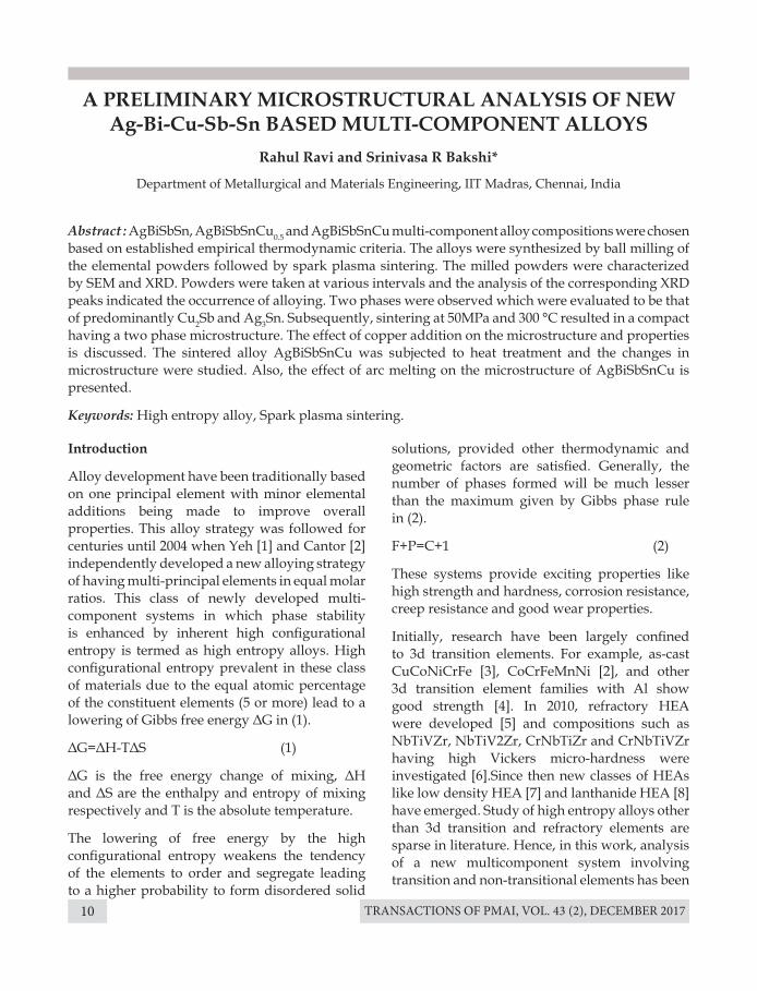
The SEM image of AgBiCuSbSn indicate a two phase microstructure (Fig 1) which were evaluated to be that of predominantly Cu2Sb and Ag3Sn with Bi segregation. This has been confirmed from the EDS analysis. The back scattered image from SEM have been produced for the three alloys namely AgBiSbSn, AgBiSbSnCu0.5 and AgBiSbSnCu in
Results and discussion
Table 1. Parameters upon Copper addition. Notice the change in values as alloy changes from AgBiSbSn to
AgBiCuSbSn.
Fig.1: Two phase microstructure of AgBiCuSbSn showing Cu2Sb phase (dark) along with Ag3Sn.
TRANSACTIONS OF PMAI, VOL. 43 (2), DECEMBER 201712
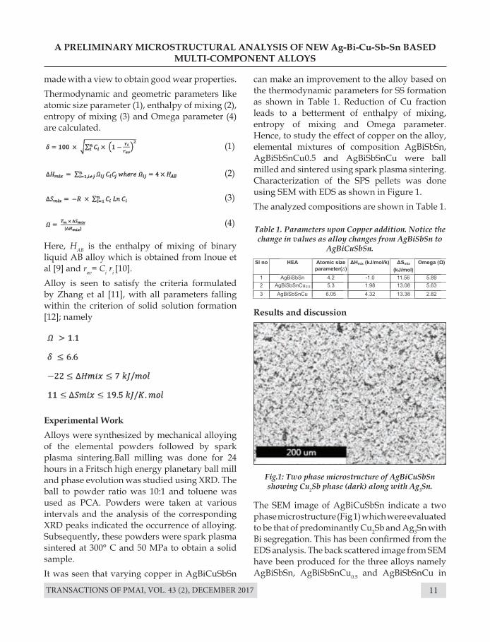
Fig 2. The faction of Cu2Sb can be seen to increase with Cu addition as it should be the case. Higher amount of Cu2Sb leads to an increase in hardness from 61.6 VHN in AgBiSbSnto 100.2 VHN in AgBiCuSbSn.
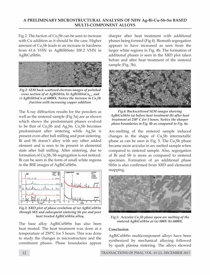
The X-ray diffraction results for the powders as well as the sintered sample (Fig 3a) are as shown which shows the predominant phases evolved to be that of Cu2Sb and Ag3Sn. Cu2Sb becomes predominant after sintering while Ag3Sn is present even after ball milling and post sintering. Bi and Sb doesn’t alloy with any other added element and is seen to be present in elemental state after ball milling. After sintering, due to formation of Cu2Sb, Sb segregation is not noticed. Bi can be seen in the form of small white regions in the BSE images of AgBiCuSbSn.
The base alloy AgBiCuSbSn has also been heat treated. The heat treatment was done at a temperature of 250°C for 5 hours. This was done to study the changes in microstructure and the constituent phases. Phase boundaries appear
ConclusionAgBiCuSbSn multicomponent alloys have been synthesized by mechanical alloying followed by spark plasma sintering. The alloys showed
A PRELIMINARY MICROSTRUCTURAL ANALYSIS OF NEW Ag-Bi-Cu-Sb-Sn BASED MULTI-COMPONENT ALLOYS
Fig.2: SEM back scattered electron images of polished cross section of a) AgBiSbSn, b) AgBiSbSnCu0.5, and
c) AgBiSbSnCu at 6000X. Notice the increase in Cu2Sb fraction with increasing copper addition
Fig.4: Backscattered SEM images showing AgBiCuSbSn (a) before heat treatment (b) after heat treatment at 250° C for 5 hours. Notice the sharper phase boundaries in Fig. 4b as compared to Fig. 4a.
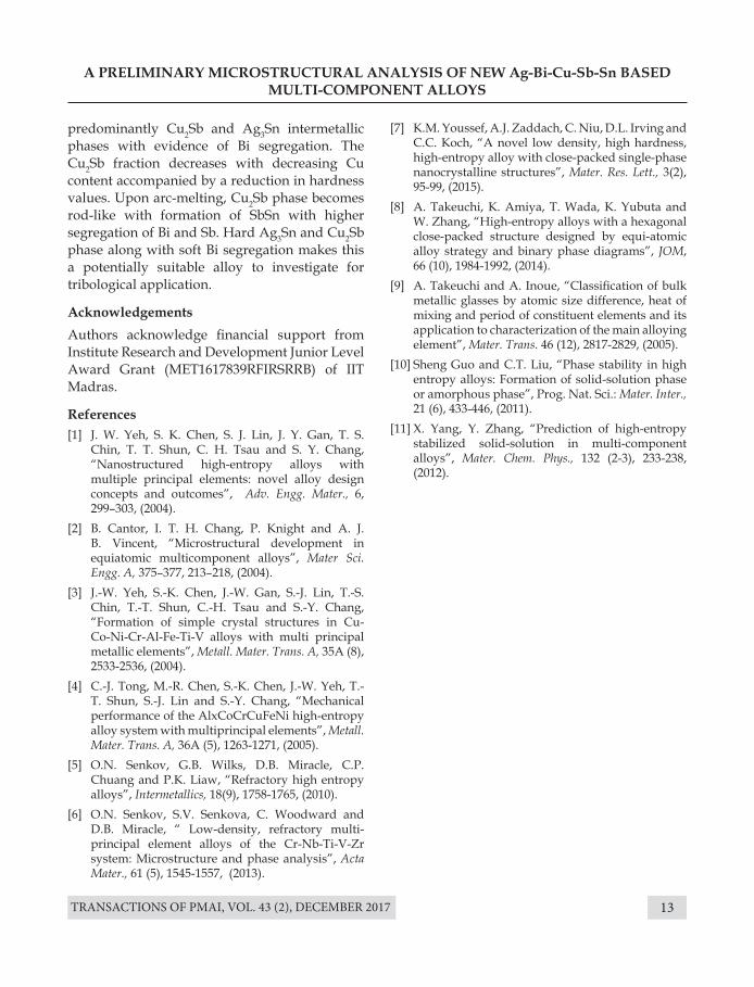
Fig.5: Acicular Cu2Sb phase upon arc melting of the sintered AgBiCuSbSn at (a) 800X (b) 6000X.
Fig.3: XRD plot of phase evolution of (a) AgBiCuSbSn through MA and subsequent sintering (b) pre and post
heat treated AgBiCuSbSn alloy.
sharper after heat treatment with additional phases being formed (Fig 4). Bismuth segregation appears to have increased as seen from the larger white regions in Fig. 4b. The formation of additional phases is seen in the XRD plot taken before and after heat treatment of the sintered sample (Fig. 3b).
Arc-melting of the sintered sample induced changes in the shape of Cu2Sb intermetallic phase as can be seen in Fig. 5. The Cu2Sb phase became more acicular in arc melted sample when compared to sintered sample. Also, segregation of Bi and Sb is more as compared to sintered specimen. Formation of an additional phase SbSn is also confirmed from XRD and elemental mapping.
TRANSACTIONS OF PMAI, VOL. 43 (2), DECEMBER 2017 13
A PRELIMINARY MICROSTRUCTURAL ANALYSIS OF NEW Ag-Bi-Cu-Sb-Sn BASED MULTI-COMPONENT ALLOYS
predominantly Cu2Sb and Ag3Sn intermetallic phases with evidence of Bi segregation. The Cu2Sb fraction decreases with decreasing Cu content accompanied by a reduction in hardness values. Upon arc-melting, Cu2Sb phase becomes rod-like with formation of SbSn with higher segregation of Bi and Sb. Hard Ag3Sn and Cu2Sb phase along with soft Bi segregation makes this a potentially suitable alloy to investigate for tribological application.
AcknowledgementsAuthors acknowledge financial support from Institute Research and Development Junior Level Award Grant (MET1617839RFIRSRRB) of IIT Madras.
References[1] J. W. Yeh, S. K. Chen, S. J. Lin, J. Y. Gan, T. S.
Chin, T. T. Shun, C. H. Tsau and S. Y. Chang, “Nanostructured high-entropy alloys with multiple principal elements: novel alloy design concepts and outcomes”, Adv. Engg. Mater., 6, 299–303, (2004).
[2] B. Cantor, I. T. H. Chang, P. Knight and A. J. B. Vincent, “Microstructural development in equiatomic multicomponent alloys”, Mater Sci. Engg. A, 375–377, 213–218, (2004).
[3] J.-W. Yeh, S.-K. Chen, J.-W. Gan, S.-J. Lin, T.-S. Chin, T.-T. Shun, C.-H. Tsau and S.-Y. Chang, “Formation of simple crystal structures in Cu-Co-Ni-Cr-Al-Fe-Ti-V alloys with multi principal metallic elements”, Metall. Mater. Trans. A, 35A (8), 2533-2536, (2004).
[4] C.-J. Tong, M.-R. Chen, S.-K. Chen, J.-W. Yeh, T.-T. Shun, S.-J. Lin and S.-Y. Chang, “Mechanical performance of the AlxCoCrCuFeNi high-entropy alloy system with multiprincipal elements”, Metall. Mater. Trans. A, 36A (5), 1263-1271, (2005).
[5] O.N. Senkov, G.B. Wilks, D.B. Miracle, C.P. Chuang and P.K. Liaw, “Refractory high entropy alloys”, Intermetallics, 18(9), 1758-1765, (2010).
[6] O.N. Senkov, S.V. Senkova, C. Woodward and D.B. Miracle, “ Low-density, refractory multi-principal element alloys of the Cr-Nb-Ti-V-Zr system: Microstructure and phase analysis”, Acta Mater., 61 (5), 1545-1557, (2013).
[7] K.M. Youssef, A.J. Zaddach, C. Niu, D.L. Irving and C.C. Koch, “A novel low density, high hardness, high-entropy alloy with close-packed single-phase nanocrystalline structures”, Mater. Res. Lett., 3(2), 95-99, (2015).
[8] A. Takeuchi, K. Amiya, T. Wada, K. Yubuta and W. Zhang, “High-entropy alloys with a hexagonal close-packed structure designed by equi-atomic alloy strategy and binary phase diagrams”, JOM, 66 (10), 1984-1992, (2014).
[9] A. Takeuchi and A. Inoue, “Classification of bulk metallic glasses by atomic size difference, heat of mixing and period of constituent elements and its application to characterization of the main alloying element”, Mater. Trans. 46 (12), 2817-2829, (2005).
[10] Sheng Guo and C.T. Liu, “Phase stability in high entropy alloys: Formation of solid-solution phase or amorphous phase”, Prog. Nat. Sci.: Mater. Inter., 21 (6), 433-446, (2011).
[11] X. Yang, Y. Zhang, “Prediction of high-entropy stabilized solid-solution in multi-component alloys”, Mater. Chem. Phys., 132 (2-3), 233-238, (2012).
TRANSACTIONS OF PMAI, VOL. 43 (2), DECEMBER 201714
VACUUM SINTERING AS A COST EFFECTIVE SINTERING PROCESS
S. R Sundaram, U. Nagarajan, D. Jayaprakash Narayanan
Powder Metallurgy Division, Pricol Ltd, Coimbatore, India.
Introduction
Compacting and Sintering are vital process stages in making a PM part, besides powder preparation. Many innovations have been done on compaction presses making them produce a crack-free, close tolerance green part. Similarly a lot of innovations have been done on sintering furnaces. The common sintering furnace uses a mesh belt as a conveyor and is a continuous furnace, when using the furnace to sinter parts at 1120°Celsius.
However, when one wants to sinter parts at higher temperature say 1250°Celsius, the situation changes. The high temperature furnaces use other methods of transportation like Walking beams or a Tray Pusher. Then the conveying mechanisms, keeping trays in good condition, the atmospheres used and maintaining these furnaces become very complex.
It was being explored in this study to find any furnace that will be flexible for use at 1120°C or
Abstract : Vacuum carburizing is an accepted process in recent times, but sintering in vacuum? The objections that come to mind are: a) It is a time consuming process; b) It will be very expensive; c) The production sintering equipment are continuous and Vacuum sintering equipment are in batch mode and would not meet the production rates needed. On the other hand, the factors favoring are: a) Sintering furnaces cost these days as much as a Vacuum heat treatment / sintering furnace, b) The vacuum sintering furnace offers flexibility of operation in terms of temperature, i.e. it can be operated at 1120oC, or 1250 oC , making it suitable for high temperature sintering, c) Sinter hardening with no special attachments, d) In addition you do not need to use any Ammonia gas, which generates the hydrogen in sintering atmosphere. In this study it was found that contrary to expectations the cost and production rates in Vacuum sintering could be comparable to regular sintering furnace besides saving in LPG and Ammonia and Nitrogen gas.
Key Words: Vacuum, Sintering, High temperature, Cost-effectiveness.
say at 1250°C, can do Sinter hardening without the complex fast cool attachment. To achieve this objective, we did trials with a Vacuum Carburizing furnace, but operating at 1250°C as a sintering furnace, to achieve sinter hardening of parts.
Need for High Temperature Sintering:
Some sintered parts need a high temperature sintering, to achieve the strength / density requirement. If we were to develop these parts we had to look for a cost effective high temperature sintering, and materials.
Materials without Nickel:
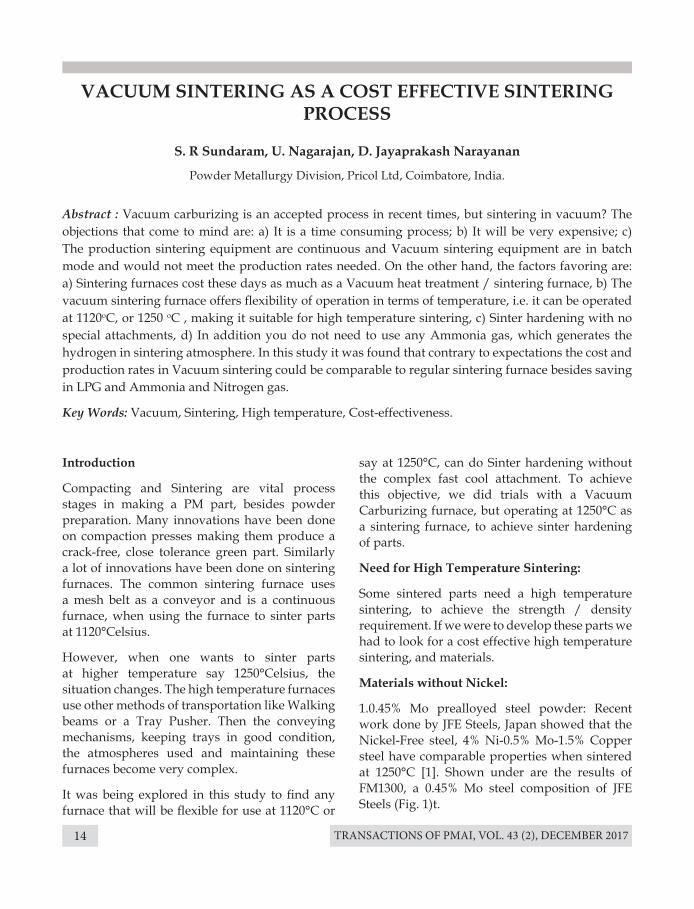
1.0.45% Mo prealloyed steel powder: Recent work done by JFE Steels, Japan showed that the Nickel-Free steel, 4% Ni-0.5% Mo-1.5% Copper steel have comparable properties when sintered at 1250°C [1]. Shown under are the results of FM1300, a 0.45% Mo steel composition of JFE Steels (Fig. 1)t.
TRANSACTIONS OF PMAI, VOL. 43 (2), DECEMBER 2017 15
VACUUM SINTERING AS A COST EFFECTIVE SINTERING PROCESS
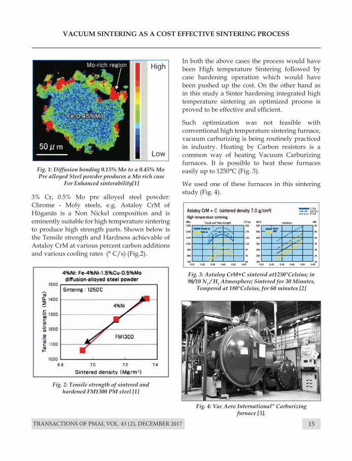
3% Cr, 0.5% Mo pre alloyed steel powder: Chrome - Moly steels, e.g. Astaloy CrM of Höganäs is a Non Nickel composition and is eminently suitable for high temperature sintering to produce high strength parts. Shown below is the Tensile strength and Hardness achievable of Astaloy CrM at various percent carbon additions and various cooling rates (° C/s) (Fig.2).
In both the above cases the process would have been High temperature Sintering followed by case hardening operation which would have been pushed up the cost. On the other hand as in this study a Sinter hardening integrated high temperature sintering an optimized process is proved to be effective and efficient.
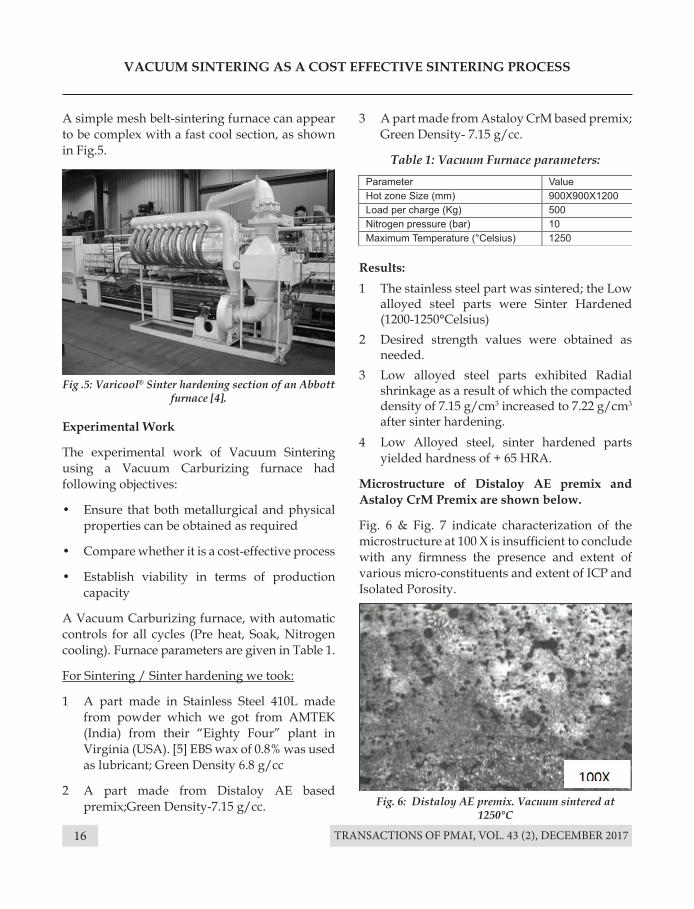
Such optimization was not feasible with conventional high temperature sintering furnace, vacuum carburizing is being routinely practiced in industry. Heating by Carbon resistors is a common way of heating Vacuum Carburizing furnaces. It is possible to heat these furnaces easily up to 1250°C (Fig. 3).
We used one of these furnaces in this sintering study (Fig. 4).
Fig. 1: Diffusion bonding 0.15% Mo to a 0.45% Mo Pre alloyed Steel powder produces a Mo rich case
For Enhanced sinterability[1]
Fig. 3: Astaloy CrM+C sintered at1250°Celsius; in 90/10 N2 / H2 Atmosphere; Sintered for 30 Minutes,
Tempered at 180°Celsius, for 60 minutes [2]
Fig. 4: Vac Aero International” Carburizing furnace [3].
Fig. 2: Tensile strength of sintered and hardened FM1300 PM steel [1]
TRANSACTIONS OF PMAI, VOL. 43 (2), DECEMBER 201716
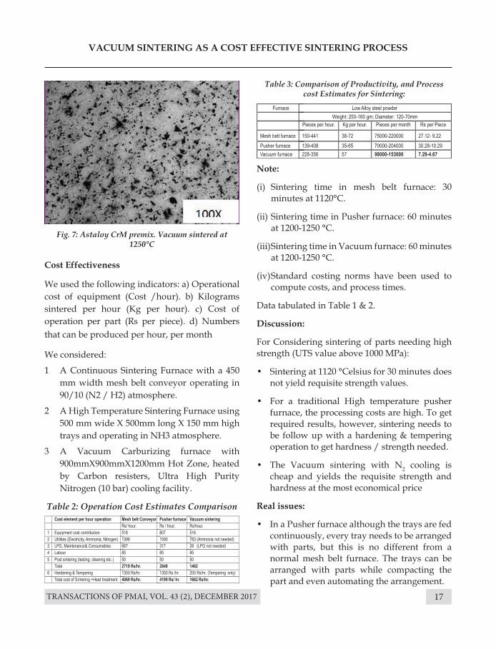
Fig .5: Varicool® Sinter hardening section of an Abbott furnace [4].
Fig. 6: Distaloy AE premix. Vacuum sintered at 1250°C
VACUUM SINTERING AS A COST EFFECTIVE SINTERING PROCESS
Experimental Work
The experimental work of Vacuum Sintering using a Vacuum Carburizing furnace had following objectives:
• Ensure that both metallurgical and physical properties can be obtained as required
• Compare whether it is a cost-effective process
• Establish viability in terms of production capacity
A Vacuum Carburizing furnace, with automatic controls for all cycles (Pre heat, Soak, Nitrogen cooling). Furnace parameters are given in Table 1.
For Sintering / Sinter hardening we took:
1 A part made in Stainless Steel 410L made from powder which we got from AMTEK (India) from their “Eighty Four” plant in Virginia (USA). [5] EBS wax of 0.8% was used as lubricant; Green Density 6.8 g/cc
2 A part made from Distaloy AE based premix;Green Density-7.15 g/cc.
Results:1 The stainless steel part was sintered; the Low
alloyed steel parts were Sinter Hardened (1200-1250°Celsius)
2 Desired strength values were obtained as needed.
3 Low alloyed steel parts exhibited Radial shrinkage as a result of which the compacted density of 7.15 g/cm3 increased to 7.22 g/cm3 after sinter hardening.
4 Low Alloyed steel, sinter hardened parts yielded hardness of + 65 HRA.
Microstructure of Distaloy AE premix and Astaloy CrM Premix are shown below.
Fig. 6 & Fig. 7 indicate characterization of the microstructure at 100 X is insufficient to conclude with any firmness the presence and extent of various micro-constituents and extent of ICP and Isolated Porosity.
3 A part made from Astaloy CrM based premix; Green Density- 7.15 g/cc.
Table 1: Vacuum Furnace parameters:
A simple mesh belt-sintering furnace can appear to be complex with a fast cool section, as shown in Fig.5.
TRANSACTIONS OF PMAI, VOL. 43 (2), DECEMBER 2017 17
Fig. 7: Astaloy CrM premix. Vacuum sintered at 1250°C
Table 3: Comparison of Productivity, and Process cost Estimates for Sintering:
VACUUM SINTERING AS A COST EFFECTIVE SINTERING PROCESS
Cost Effectiveness
We used the following indicators: a) Operational cost of equipment (Cost /hour). b) Kilograms sintered per hour (Kg per hour). c) Cost of operation per part (Rs per piece). d) Numbers that can be produced per hour, per month
We considered:
1 A Continuous Sintering Furnace with a 450 mm width mesh belt conveyor operating in 90/10 (N2 / H2) atmosphere.
2 A High Temperature Sintering Furnace using 500 mm wide X 500mm long X 150 mm high trays and operating in NH3 atmosphere.
3 A Vacuum Carburizing furnace with 900mmX900mmX1200mm Hot Zone, heated by Carbon resisters, Ultra High Purity Nitrogen (10 bar) cooling facility.
Table 2: Operation Cost Estimates Comparison
Note:
(i) Sintering time in mesh belt furnace: 30 minutes at 1120°C.
(ii) Sintering time in Pusher furnace: 60 minutes at 1200-1250 °C.
(iii) Sintering time in Vacuum furnace: 60 minutes at 1200-1250 °C.
(iv) Standard costing norms have been used to compute costs, and process times.
Data tabulated in Table 1 & 2.
Discussion:
For Considering sintering of parts needing high strength (UTS value above 1000 MPa):
• Sintering at 1120 °Celsius for 30 minutes does not yield requisite strength values.
• For a traditional High temperature pusher furnace, the processing costs are high. To get required results, however, sintering needs to be follow up with a hardening & tempering operation to get hardness / strength needed.
• The Vacuum sintering with N2 cooling is cheap and yields the requisite strength and hardness at the most economical price
Real issues:
• In a Pusher furnace although the trays are fed continuously, every tray needs to be arranged with parts, but this is no different from a normal mesh belt furnace. The trays can be arranged with parts while compacting the part and even automating the arrangement.
TRANSACTIONS OF PMAI, VOL. 43 (2), DECEMBER 201718
• On the other hand the Vacuum furnace considered in this study is truly a batch furnace, the parts being charged at room temperature, in fixtures, and the furnace then goes through heating and cooling for every cycle. The furnace will have to be charged at every cycle.
• While the type of parts taken for study, (70-120mm diameter; 150-250gm weight) are suitable to be loaded in fixtures used by the Vacuum furnace, it remains to be seen how effectively one can load small parts (40-50 mm diameter; 30-70 gm weight).
Conclusions:
This study demonstrated successfully making a high strength part, using a cheaper low alloy steel powder with no Nickel, and a cost effective high temperature sintering process.
• To impart a very high strength in the parts, they need to be sintered at 1250 °C. For this work Vacuum sintering is very cost effective and can meet volume requirements of as good as Mesh belt, or Pusher furnaces.
o Sinter hardening of the parts is possible and it can be achieved with consequent savings and avoiding additional distortion.
• Sintering large parts at 1120 °C also Vacuum sintering can work.
o In conventional mesh belt furnaces, less numberof large heavy parts fit in available belt space, forcing use of larger mesh belt width and longer sintering zones to get reasonable quantity of parts sintered.
• To sinter small parts for medium strength applications, a regular mesh belt furnace would work well. However a Fast Cooling Section like the Varicool® Section of Abbott Furnaces of USA [4] would be needed for any sinter hardening.
VACUUM SINTERING AS A COST EFFECTIVE SINTERING PROCESS
In practice in India, the number of parts needing High temperature sintering, or sinter hardening are not a huge number.
So it would be practical to have regular Mesh belt sintering furnaces of 600 MM belt width, and may be use a Vacuum sintering furnace, for parts to be sintered at 1200-1250°Celsius, as also for parts which need sinter-hardening.
References:
[1] Bernard Williams, “JFE Steel Broadens iron powder range for high performance powder metallurgy parts”, in “PM _Review”, Single Edition; Page 61, (2013)
[2] “Product Data Sheets” Höganäs”; (2006)
[3] Vac aero International; “Selecting the Right Vacuum furnace for the job”; Dan Herring; April, (2013).
[4] Abbot Engineering and Technology, “Varicool® Convective cooling system”, 28th May (2015).
[5] ”Product Data sheet”. Amtek (India), Page 16, “MVS-410 L”, June (2016).
TRANSACTIONS OF PMAI, VOL. 43 (2), DECEMBER 2017 19
THE EFFECT OF SINTERING PROCESS PARAMETRS ON FINAL DENSITY OF SINTRED PARTS PRODUCED BY USING
METAL INJECTION MOLDING (MIM)
Praveen Pachauri1, Md. Hamiuddin2
1 Noida Institute of Engineering and Technology, Greater Noida, India. 2 Aligarh Muslim University, Aligarh, India.
Introduction Metal injection moulding (MIM) is an emerging technology to process metal powders into parts of desired shapes. The MIM process combines the traditional shape-making capability of plastic injection moulding and materials flexibility of powder metallurgy [1]. The process consists of four main steps: mixing, injection moulding, debinding and sintering [2]. During injection moulding a green part with the desired shape is formed by the feedstock flow into a mold under pressure. After moulding, the binder holds the particles in place. The binder is then removed in the debinding step and the debound part is sintered to achieve the required mechanical properties. The geometrical accuracy and mechanical properties of the final parts after sintering depend strongly on the process parameters in the different stages [3,4]. Although the MIM process offers many advantages, it
Abstract : This work is intended to find the effect of five controllable process parameters during sintering process on final density. These parameters include the sintering temperature, heating rate, sintering time, cooling rate, and sintering atmosphere. The experiment was conducted using Taguchi methodology. The experimental results were converted into S/N values for optimization of parameters. The analysis of variance (ANOVA) was used to find the confidence level and the variance of the data. It is observed that out of the five factors, four are the significant factors. The sintering temperature has a contribution of 14.37% at a confidence level of 95%, heating rate has a contribution of 14.65% at a confidence level of 95%, sintering time has a contribution of 59.58% at a confidence level of 99%, cooling rate has a contribution of 10.70% with a confidence level of 95%, and sintering atmosphere is observed to be an insignificant factor for density of the specimen. It is also noted from the rank of parameters that the variation in the S/N ratio value with the change in the value of the parameter is maximum for sintering time and minimum for sintering atmosphere.
Keywords: Metal Injection Molding, sintering, analysis of variance, Taguchi methodology
requires proper moulding condition. The classical Design of Experiment (DOE) technique has been used by many authors [5-7] for optimization of single process parameters at a time. In order to obtain high efficiency in the planning and analysis of experimental data, the Taguchi method is recognized as a systematic approach for design and analysis of experiments to improve product quality [8-9]. The Taguchi method has been applied by many authors to investigate and optimize the process parameters [10-14]. The majority of previous investigations in MIM have focused on the sintering parameters and the amount of metal powder in the mixture. The effect of the injection moulding and debinding parameters on tensile strength of the parts produced by MIM has not yet been thoroughly investigated. The objective of this paper is to find the significant factors and their contribution in tensile strength of final part.
TRANSACTIONS OF PMAI, VOL. 43 (2), DECEMBER 201720
THE EFFECT OF SINTERING PROCESS PARAMETRS ON FINAL DENSITY OF SINTRED PARTS PRODUCED BY USING METAL INJECTION MOLDING (MIM)
Experimental Work
To make the working material, the SS316L stainless steel powder was mixed with the binder comprised of polyethylene glycol (PEG), polymethyl methacrylate (PMMA), paraffin wax and stearic acid (SA). Paraffin wax is used to decrease the feedstock viscosity and to increase replication ability of the feedstock. The main advantage of using PMMA/PEG binder is that it can be removed from the mouldings in a comparatively short time.
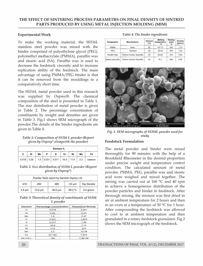
The SS316L metal powder used in this research was supplied by Osprey®. The chemical composition of the steel is presented in Table 1. The size distribution of metal powder is given in Table 2. The percentage concentration of constituents by weight and densities are given in Table 3. Fig.1 shows SEM micrograph of the powder.The details of the binder ingredients are given in Table 4.
Feedstock Formulation
The metal powder and binder were mixed thoroughly for 90 minutes with the help of a Brookfield Rheometer in the desired proportion under precise weight and temperature control condition. The calculated amount of metal powder, PMMA, PEG, paraffin wax and stearic acid were weighed and mixed together. The mixing was carried out at 160 °C and 40 rpm to achieve a homogeneous distribution of the powder particles and binder in feedstock. After thorough mixing, the mixture was first dried in air at ambient temperature for 2 hours and then in an oven at a temperature of 50 °C for 1 hour. After compounding the feedstock was allowed to cool to at ambient temperature and then granulated in a rotary feedstock granulator. Fig.2 shows the SEM micrograph of the feedstock.
Table 1: Composition of SS316 L powder (Report given by Osprey® alongwith the powder)
Table 4: The binder ingredients
Fig. 1. SEM micrographs of SS316L powder used for study
Table 3: Theoretical density of constituents of SS316 L powder
Table 2: Size distribution of SS316 L powder (Report given by Osprey®)
TRANSACTIONS OF PMAI, VOL. 43 (2), DECEMBER 2017 21
THE EFFECT OF SINTERING PROCESS PARAMETRS ON FINAL DENSITY OF SINTRED PARTS PRODUCED BY USING METAL INJECTION MOLDING (MIM)
Production of Test Specimen
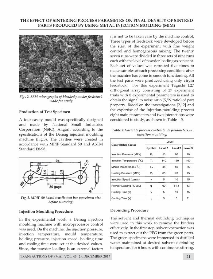
A four-cavity mould was specifically designed and made by National Small Industries Corporation (NSIC), Aligarh according to the specifications of the Demag injection moulding machine (Fig.3). The cavities were created in accordance with MPIF Standard 50 and ASTM Standard E8-98.
Injection Moulding Procedure
In the experimental work, a Demag injection moulding machine with microprocessor control was used. On the machine, the injection pressure, injection temperature, mould temperature, holding pressure, injection speed, holding time and cooling time were set at the desired values. Since, the powder loading is an external factor;
Fig . 2. SEM micrographs of blended powder feedstock made for study
Table 5: Variable process controllable parameters in injection moulding:
Fig. 3. MPIF-50 based tensile test bar (specimen size before sintering)
it is not to be taken care by the machine control. Three types of feedstock were developed before the start of the experiment with fine weight control and homogeneous mixing. The twenty seven runs were divided in three sets of nine runs each with the level of powder loading as constant. Each set of values was repeated five times to make samples at each processing conditions after the machine has come to smooth functioning. All the test parts were produced using only virgin feedstock. For this experiment Taguchi L27 orthogonal array consisting of 27 experiment trials with 8 experimental parameters is used to obtain the signal to noise ratio (S/N ratio) of part property. Based on the investigations [2,12] and the expertise of the injection-moulding process eight main parameters and two interactions were considered to study, as shown in Table – 5.
Debinding Procedure
The solvent and thermal debinding techniques were used in this work to remove the binders effectively. In the first step, solvent extraction was used to extract out the PEG from the green parts. The green specimens were immersed in distilled water maintained at desired solvent debinding temperature for 6 hours with continuous stirring.
TRANSACTIONS OF PMAI, VOL. 43 (2), DECEMBER 201722
The leached specimens were then dried in an oven to completely remove the remains of water and then cooled. Thermal debinding was used to remove the PMMA, paraffin wax and stearic acid after solvent debinding. The leached specimens were put into an alumina tray in which the surrounding space was filled with alumina powder to avoid any distortion of the specimens. Various parameters in debinding are shown in Table – 6.
The required response the analysis of the trend of performance characteristics with respect to variation of the controllable factor are shown in Fig. 4.
Sintering Procedure
For sintering the brown parts were first pre-sintered then sintered. The peak temperature for pre-sintering after debinding was kept 900°C. The pre-sintered specimens were sintered afterwards in a batch furnace desired conditions, process parameters as shown in Table - 7.
Results
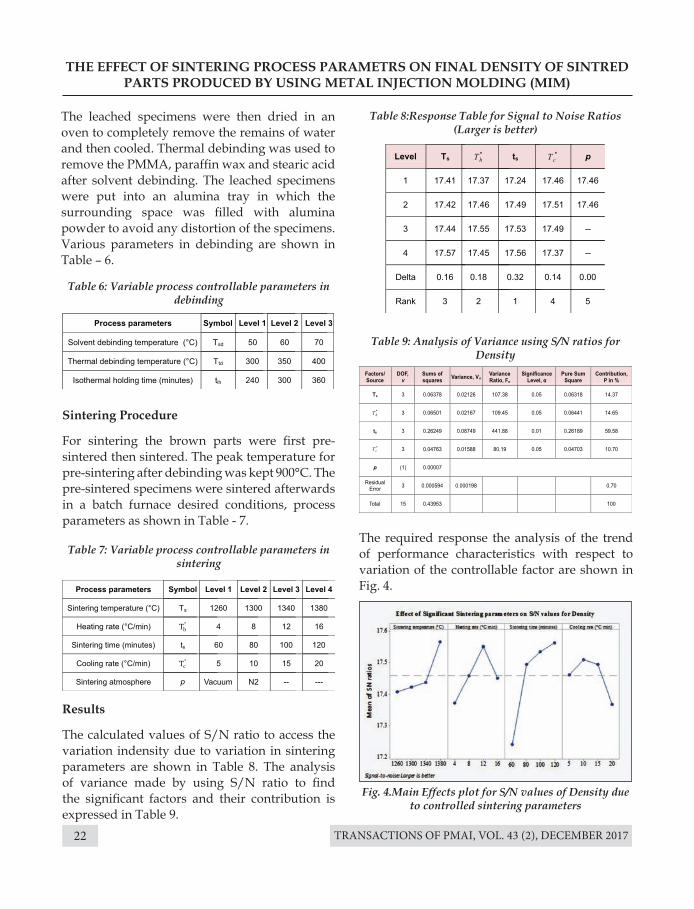
The calculated values of S/N ratio to access the variation indensity due to variation in sintering parameters are shown in Table 8. The analysis of variance made by using S/N ratio to find the significant factors and their contribution is expressed in Table 9.
THE EFFECT OF SINTERING PROCESS PARAMETRS ON FINAL DENSITY OF SINTRED PARTS PRODUCED BY USING METAL INJECTION MOLDING (MIM)
Table 6: Variable process controllable parameters in debinding
Table 8:Response Table for Signal to Noise Ratios (Larger is better)
Table 9: Analysis of Variance using S/N ratios for Density
Fig. 4.Main Effects plot for S/N values of Density due to controlled sintering parameters
Table 7: Variable process controllable parameters in sintering
TRANSACTIONS OF PMAI, VOL. 43 (2), DECEMBER 2017 23
THE EFFECT OF SINTERING PROCESS PARAMETRS ON FINAL DENSITY OF SINTRED PARTS PRODUCED BY USING METAL INJECTION MOLDING (MIM)
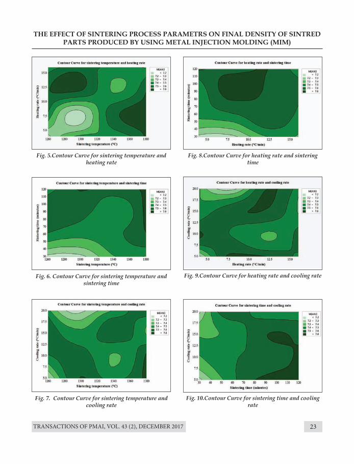
Fig. 5.Contour Curve for sintering temperature and heating rate
Fig. 8.Contour Curve for heating rate and sintering time
Fig. 9.Contour Curve for heating rate and cooling rate
Fig. 10.Contour Curve for sintering time and cooling rate
Fig. 6. Contour Curve for sintering temperature and sintering time
Fig. 7. Contour Curve for sintering temperature and cooling rate
TRANSACTIONS OF PMAI, VOL. 43 (2), DECEMBER 201724
THE EFFECT OF SINTERING PROCESS PARAMETRS ON FINAL DENSITY OF SINTRED PARTS PRODUCED BY USING METAL INJECTION MOLDING (MIM)
Discussion
The effect of sintering process parameters can be observed from Fig. 6 to 10. Sintering temperature is one of the most significant process parameter of sintering process. When we study the effect of sintering temperature on densification of SS316L, it is observed that the densification of SS316L powder begins at sintering temperature of about 1260 °C. The sintering begins slowly in the initial stage, but soon it causes rapid shrinkage in the intermediate stage; afterwards the shrinkage becomes much slower in the final stage to finish the sintering process. The densification occur mainly in the heating period. Heating rate is also one of the significant process parameter of sintering process as it affects the densification of the sintered part. The densification is observed to be best at a heating rate of 12 ºC/min.Sintering time is also a significant factor for densification. During this time at sintering temperature the closed pores continue to reduce or vanish and the grain size increase. The cooling rate is also a significant factor for densification but its contribution is low as compared to other parameters.A comparatively high cooling rate of 10 ºC/min is desirable for perfect densification. The sintering atmosphere is an insignificant factor. It can be noted that high densification occurs at sintering temperature of 1380 ºC alongwith sintering time of 100 minutes, heating rate of 8 ºC/min and cooling rate of 5 ºC/min. The actual working range for sintering temperature is 1350 ºC to 1380 ºC, heating rate of 6.5 ºC/min to 11 ºC/min, sintering time of 80 to 120 minutes and cooling rate of 5 ºC/min to 10 ºC/min. It is also notable that lower sintering time and high cooling rate may cause detrimental effects.
Conclusion
From Table 9, it can be observed that out of the five factors four are the significant factors. Since, there is one insignificant factor, so pooling is
required. The sintering temperature (Ts) has a contribution of 14.37% at a confidence level of 95%, heating rate (T°h) has a contribution of 14.65% at a confidence level of 95%, sintering time (ts) has a contribution of 59.58% at a confidence level of 99%, cooling rate (T°c) has a contribution of 10.70% with a confidence level of 95%, and sintering atmosphere is observed to be insignificant factor for density by the specimen.
The optimum level of parameters can be obtained by selecting the highest values of S/N ratios from respective column in Table 8. The optimum level for Density occurs at (Ts)4(T°h)3(ts)4(T°c)2(p)2. From Table 8 it can also be noted from the rank of parameters that the variation in the S/N ratio value with the change in the value of the parameter is maximum for sintering time and minimum for sintering atmosphere.
References [1] R.M. German and A. Bose, “Injection Moulding of
metals and ceramics”, (Metal Powder Industries Federation, Princeton, NJ, (1997).
[2] B. Berginc, Z. Kampus, and B. Sustarsic, ”The use of Taguchi approach to determine the influence of injection moulding parameters on the properties of green parts”, J. Achiev. Mater.Manuf. Engg., 15, 63-70, (2006)
[3] R.M.German, “Homogeneity effects on feedstock viscosity in powder injection moulding”, J. Am. Ceram. Soc., 77(1), 283– 285, (1994).
[4] T. Barriere, B. Liu and J.C. Gelin, “Determination of the optimal parameters in the metal injection moulding from experiments and numerical modeling”, J. Mater.Process.Tech., 143-144, 636-644, (2003).
[5] D.F.Heaney, R. Zauner, C. Binet, K. Cowan, J. Piemme, “Variability of powder characteristics and their effect on dimensional variability of powder injection moulded components”, Powder Metallurgy,47 (2), 145-150, (2004).
[6] W.C.J. Wei, R.Y. Wu, S.J. Ho, “Effects of pressure parameters on alumina made by powder injection moulding”, J. Eur. Ceram. Soc., 20, 1301-1310, (2000).
TRANSACTIONS OF PMAI, VOL. 43 (2), DECEMBER 2017 25
THE EFFECT OF SINTERING PROCESS PARAMETRS ON FINAL DENSITY OF SINTRED PARTS PRODUCED BY USING METAL INJECTION MOLDING (MIM)
[7] Y. Li Y., L. Li, and K.A. Khalil, “Effect of powder loading on metal injection moulding stainless steel”, J. Mater. Process.Tech., 183, 432–439, (2007).
[8] P.J. Ross, “Taguchi Techniques for Quality Engineering”, Tata McGraw Hill, (1996).
[9] R.K. Roy, “Design of Experiments Using the Taguchi Approach,” John Wiley & Sons, (2001).
[10] Y.S. Zu and S.T. Lin, “Optimising the mechanical properties of injection molded W-4.9% Ni-2,1% Fe in debinding”, J. Mater. Process.Tech., 71, 337-342, (1997).
[11] C.H. Ji, N.H. Loh, K.A. Khor and S.B.Tor, “Sintering study of stainless steel metal injection moulding parts using Taguchi method: final density”, Mater. Sci. &Engg.A311, 74-82, (2001).
[12] W.J. Tseng, “Statistical analysis of process parameters influencing dimensional control in ceramic injection moulding”, J. Mater. Process.Tech., 79, 242-250, (1998).
[13] K.R. Jamaludin, N. Muhamad, M.A. Rahman, S.R.M. Amin and Muntadhahadi, “Analysis of variance on the metal injection Moulding parameters using a bimodal particle size distribution feedstock”, (Proc. Int. Conf. on Mechanical & Manufacturing Engineering, ISBN 97-98-2963-59-2). (2008)
[14] R.K. Roy, “A primer on the Taguchi method”, Competitive Manufacturing Series, 247, Van Nostrand Reinhold, New York, (1990).
[15] D.P. Mandic and J.A. Chambers, “Recurrent Neural Networks for Prediction”, (Wiley Series in Adaptive and Learning Systems for Signal Processing, Communications and Control, (2002).
[16] I. Aleksander and H. Morton, “An Introduction to Neural Computing”, Chapman and Hall, London, (1990).
[17] S.Haykin, “Neural Networks: A Comprehensive Foundation”, Pearson Education, (1999).
[18] R.M. German, “Sintering Theory and Practice”, Wiley, New York, (1996).
[19] J.M. Zurada, “Introduction to Artificial Neural Systems”, Jaico Publication, India, (1996).
[20] J.A. Anderson, “An introduction to Neural Networks”, MIT Press, Cambridge, (1995).
[21] C.H.Chen, “Fuzzy Logic and Neural Network Handbook”, McGraw-Hill, New York, (1996).
[22] B.H.M. Sadeghi, “A BP-neural network predictor model for plastic injection molding process”, J. Mater.Process.Tech., 103, 411-416, (2000).
TRANSACTIONS OF PMAI, VOL. 43 (2), DECEMBER 201726
PROPERTIES OF IMMISCIBLE Cu-20 wt. % Mo ALLOY PREPARED BY HIGH ENERGY BALL MILLING AND COLD
ISOSTATIC PRESSING
P. Sengupta*,M. Debata, K. Jayasankara
CSIR – Institute of Minerals and Materials Technology, Bhubaneswar, IndiaaCSIR – National Institute for Interdisciplinary Science and Technology, Thiruvananthapuram, India
Introduction
In spite of exceptional properties viz. high electrical conductivity (5.8x10⁷ S/m), high thermal conductivity (401 W/mK), excellent corrosion resistance; application of Cu in high power microwave devices is limited owing to poor mechanical properties (Vickers hardness 37 Hv) and high coefficient of linear thermal expansion (16.5x10⁻⁶/˚Cat 25 °C). The mechanical properties of Cu can be improved by theaddition of alloying elements that form asolid solution with Cu[1]. Many a time, the Cu-X alloys (where X represents the alloying element soluble in Cu) exhibit improved mechanical properties at the expense of electrical conductivity, which makes them unsuitable for applications (ex. collector regions of traveling wave tube) where thecombination of high electrical conductivity and mechanical properties are necessitated.
Therefore, in this study, efforts have been made to improve mechanical properties of Cu by alloying
Abstract : In this work, immiscible Cu-20 wt.% Mo alloy powder is prepared by high energy ball milling of pure Cu and Mo powders in a dual drive planetary ball mill. The minimum crystallite size of 11 nm was obtained after 40 h of milling. The green compacts were prepared with the help of cold isostatic pressing applying maximum pressure of 300 MPa for 15 min. The green samples were pre-sintered to remove binder and densified to 92% theoretical density by conventional sintering at 1000 ̊ C for 1 h in vacuum. Phase and microstructure analysis of sintered samples exhibited no chemical interaction between Cu and Mo. The sintered samples were analyzed for hardness, thecoefficient of linear thermal expansion and electrical conductivity. Overall, the Cu-Mo sample prepared by high energy ball milling and cold isostatic pressing offered good combination of density, hardness, CTE and electrical conductivity.
Keywords: Dual drive planetary ball mill (DDPBM); XRD; SEM; CTE; Electrical conductivity
with Mo. Since Cu-Mo system is immiscible in nature, it is expected that addition of hard Mo will improve the mechanical properties of soft Cu, without sacrificing the electrical conductivity. Due to thepositive enthalpy of mixing (+18 kJ/mol), Cu-Mo alloy is difficult to synthesize in conventional methods. However, studies reveal that immiscible Cu-Mo alloy can be prepared by mechanical alloying[2,3]; where structural refinement occur during non-equilibrium processing and uniform distribution of finely dispersed second phase is obtained [1,2,4].
In this work, Cu-20 wt. % Mo powders are milled in a specially designed dual drive planetary ball mill for different duration. The ball milled powder is consolidated by cold isostatic pressing followed by pre-sintering and sintering. Phase and microstructure analyses of ball milled powder and sintered samples were carried out. Hardness, CTE and electrical conductivity of the sintered samples were measured.
TRANSACTIONS OF PMAI, VOL. 43 (2), DECEMBER 2017 27
PROPERTIES OF IMMISCIBLE Cu-20 wt. % Mo ALLOY PREPARED BY HIGH ENERGY BALL MILLING AND COLD ISOSTATIC PRESSING
Experimental
In this work, 99.67% pure Cu (Himedia Lab, particle size <45μm (68%), 45-75μm (32%), theoretical density 8.92g/cm3) and 99.95% pure Mo (Himedia Lab, particle size 2-5 μm, theoretical density 10.22 g/cm3) were used as starting materials. High energy ball milling of Cu-20 wt% Mo powders was carried out in a specially designed dual drive planetary ball mill for 20, 30 and 40 h keeping theball to powder ratio and the rotational speed of ball mill at 10:1 and 300 rpm respectively. Tungsten carbide balls of 5 mm diameter were used as grinding media and toluene was used as awet medium. The operating principle and salient features of DDPBM may be found elsewhere[5–9].
The high energy ball milled Cu-Mo powders were characterized for phase analysis in X-ray diffractometer (PAN analytical X’pert PRO) with Cu Kα radiation (λCu = 0.154 nm), and β-filter (Ni) operated at 30 mA and 40 kV. Scanning angle was 30 to 95° with a step size of 0.02° and scanning rate of 2°/min. Crystallite size and lattice strain of high energy ball milled Cu-Mo powders are determined using following equations [10,11]:
Morphology and elemental composition of as-milled Cu-Mo powders were investigated in FESEM (Supra, Gemini55, Carl Zeiss, Germany, equipped with EDS).
40 h milled Cu-Mo powders were cold isostatic pressed (using 1 wt. % PVA as a binding agent) to 15 mm diameter and 20 mm high samples using the maximum pressure of 300 MPa and dwell time of 15 min. The powders were rammed in a rubbermold, and mold diameter was increased by 12 %. Green density of the compact was ~63 %. De-binding of CIP-ed samples was carried out in the de-binding furnace, followed by pre-sintering at 600° for 2 h. The sintering was performed in a tubular furnace at 1000° for 1 h in vacuum.
The density of sintered samples was determined by Archimedes principle. Theoretical density of Cu-20 wt. % Mo system was estimated using the inverse rule of mixture. The sintered samples were characterized for phase (XRD) and microstructure (FESEM). EDS analysis was performed to investigate the distribution of elemental Cu and Mo in the sintered product. Microhardness of the sintered samples was measured by Vickers hardness tester (Zwick/Roell ZHV) under a load of 5 kgf for a dwell time of 10s. The coefficient of linear thermal expansion of sintered sample was measured in horizontal push-rod type dilatometer (Linseis L75 platinum series) in the temperature range of 25-300 ̊ C, using heating rate of 5 ̊ C/min in argon atmosphere. The linear CTE was determined using following equation
where β is the corrected full width at half maximum (FWHM in rad), βo is the observed peak broadening and βi is the instrumental broadening (0.046˚, estimated by XRD pattern of α-Al2O3), λ is the wavelength (nm) of incident radiation (0.154 nm), K is the constant (generally, K=0.9), L is the crystallite size (in nm), θ is the Bragg’s angle of reflection (in rad) and ε is the strain in material.
where α is the coefficient of linear thermal expansion (x10-6/˚C), l is the initial length of test specimen (mm), ∆l is the change in length (mm), and ∆T is the change in temperature ˚C.
The electrical conductivity of sintered Cu-Mo alloy was measured by Technofour electrical
(1)
(2)
(4)
(3)
TRANSACTIONS OF PMAI, VOL. 43 (2), DECEMBER 201728
PROPERTIES OF IMMISCIBLE Cu-20 wt. % Mo ALLOY PREPARED BY HIGH ENERGY BALL MILLING AND COLD ISOSTATIC PRESSING
conductivity meter (Technofour) using International Annealed Copper Standard (IACS) for calibration.
Results and discussion
Effect of high energy ball milling on phase and microstructure of Cu-Mo powders:
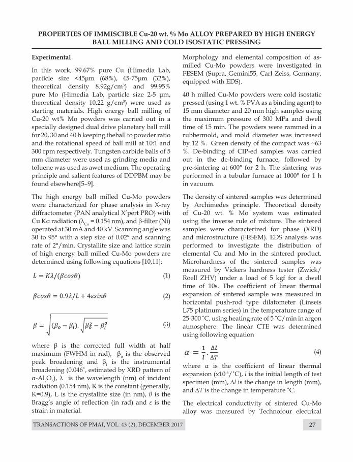
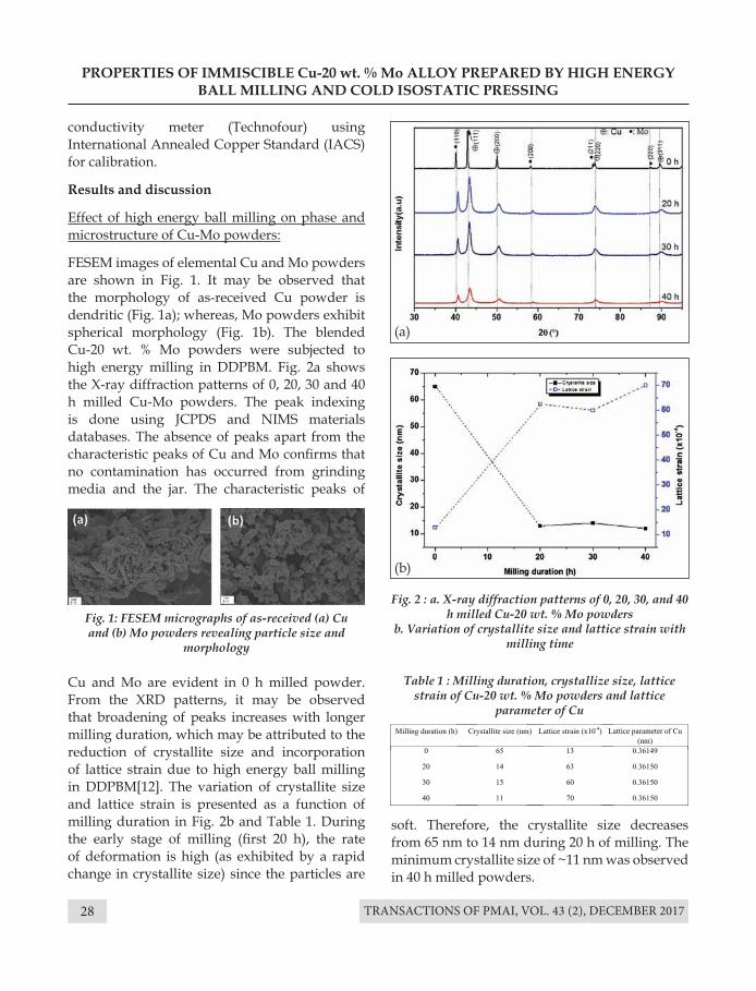
FESEM images of elemental Cu and Mo powders are shown in Fig. 1. It may be observed that the morphology of as-received Cu powder is dendritic (Fig. 1a); whereas, Mo powders exhibit spherical morphology (Fig. 1b). The blended Cu-20 wt. % Mo powders were subjected to high energy milling in DDPBM. Fig. 2a shows the X-ray diffraction patterns of 0, 20, 30 and 40 h milled Cu-Mo powders. The peak indexing is done using JCPDS and NIMS materials databases. The absence of peaks apart from the characteristic peaks of Cu and Mo confirms that no contamination has occurred from grinding media and the jar. The characteristic peaks of
Cu and Mo are evident in 0 h milled powder. From the XRD patterns, it may be observed that broadening of peaks increases with longer milling duration, which may be attributed to the reduction of crystallite size and incorporation of lattice strain due to high energy ball milling in DDPBM[12]. The variation of crystallite size and lattice strain is presented as a function of milling duration in Fig. 2b and Table 1. During the early stage of milling (first 20 h), the rate of deformation is high (as exhibited by a rapid change in crystallite size) since the particles are
Table 1 : Milling duration, crystallize size, lattice strain of Cu-20 wt. % Mo powders and lattice
parameter of Cu
Fig. 1: FESEM micrographs of as-received (a) Cu and (b) Mo powders revealing particle size and
morphology
Fig. 2 : a. X-ray diffraction patterns of 0, 20, 30, and 40 h milled Cu-20 wt. % Mo powders
b. Variation of crystallite size and lattice strain with milling time
(a)
(b)
soft. Therefore, the crystallite size decreases from 65 nm to 14 nm during 20 h of milling. The minimum crystallite size of ~11 nm was observed in 40 h milled powders.
TRANSACTIONS OF PMAI, VOL. 43 (2), DECEMBER 2017 29
PROPERTIES OF IMMISCIBLE Cu-20 wt. % Mo ALLOY PREPARED BY HIGH ENERGY BALL MILLING AND COLD ISOSTATIC PRESSING
Lattice parameter of Cu in 0, 20, 30 and 40 h milled Cu-20 wt. % Mo powders are shown in Table 1. It may be seen that change in lattice parameter of Cu is almost insignificant with milling time, which is due to negligible solid solubility of Mo in Cu and the immiscibility in Cu-Mo system according to the binary equilibrium diagram of Cu-Mo[14].
Analysis of sintered samplesDensityThe green density of cold isostatic pressed Cu-20 wt. % Mo sample was ~ 63% theoretical. The final density of the sample sintered at 1000o for 1 h in vacuum was ~ 92% theoretical. The similar sintered density of the Cu-Mo system is reported in the literature[13]. The presence of hard and non-deformable Mo particles, poor diffusional bonding between Cu and Mo phases contribute to lower sintered density.
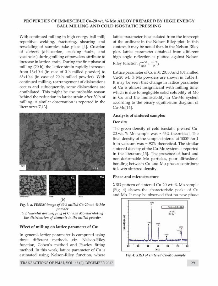
Phase and microstructure
XRD pattern of sintered Cu-20 wt. % Mo sample (Fig. 4) shows the characteristic peaks of Cu and Mo. It may be observed that no new phase
Effect of milling on lattice parameter of Cu:
In general, lattice parameter is computed using three different methods viz. Nelson-Riley function, Cohen’s method and Pawley fitting method. In this work, lattice parameter of Cu is estimated using Nelson-Riley function, where
Fig. 3: a. FESEM image of 40 h milled Cu-20 wt. % Mo powder
b. Elemental dot mapping of Cu and Mo elucidating the distribution of elements in the milled powder
Fig .4: XRD of sintered Cu-Mo sample
(b)
With continued milling in high energy ball mill; repetitive welding, fracturing, shearing and rewelding of samples take place [4]. Creation of defects (dislocation, stacking faults, and vacancies) during milling of powders attribute to increase in lattice strain. During the first phase of milling (20 h), the lattice strain rapidly increases from 13x10-4 (in case of 0 h milled powder) to 63x10-4 (in case of 20 h milled powder). With continued milling, rearrangement of dislocations occurs and subsequently, some dislocations are annihilated. This might be the probable reason behind the reduction in lattice strain after 30 h of milling. A similar observation is reported in the literatures[7,13].
(a)
lattice parameter is calculated from the intercept of the ordinate in the Nelson-Riley plot. In this context, it may be noted that, in the Nelson-Riley plot, lattice parameter obtained from different high angle reflection is plotted against NelsonRiley function
u
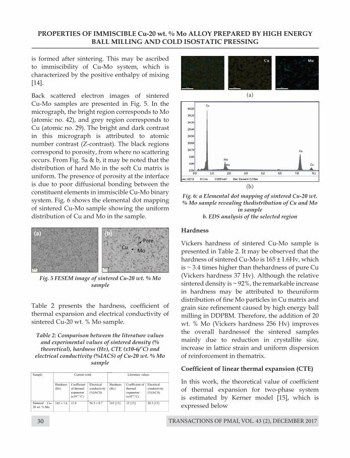
TRANSACTIONS OF PMAI, VOL. 43 (2), DECEMBER 201730
PROPERTIES OF IMMISCIBLE Cu-20 wt. % Mo ALLOY PREPARED BY HIGH ENERGY BALL MILLING AND COLD ISOSTATIC PRESSING
Table 2: Comparison between the literature values and experimental values of sintered density (% theoretical), hardness (Hv), CTE (x10-6/˚C) and
electrical conductivity (%IACS) of Cu-20 wt. % Mo sample
Fig. 5 FESEM image of sintered Cu-20 wt. % Mo sample
Fig. 6: a Elemental dot mapping of sintered Cu-20 wt. % Mo sample revealing thedistribution of Cu and Mo
in sampleb. EDS analysis of the selected region
is formed after sintering. This may be ascribed to immiscibility of Cu-Mo system, which is characterized by the positive enthalpy of mixing [14].
Back scattered electron images of sintered Cu-Mo samples are presented in Fig. 5. In the micrograph, the bright region corresponds to Mo (atomic no. 42), and grey region corresponds to Cu (atomic no. 29). The bright and dark contrast in this micrograph is attributed to atomic number contrast (Z-contrast). The black regions correspond to porosity, from where no scattering occurs. From Fig. 5a & b, it may be noted that the distribution of hard Mo in the soft Cu matrix is uniform. The presence of porosity at the interface is due to poor diffusional bonding between the constituent elements in immiscible Cu-Mo binary system. Fig. 6 shows the elemental dot mapping of sintered Cu-Mo sample showing the uniform distribution of Cu and Mo in the sample.
Hardness
Vickers hardness of sintered Cu-Mo sample is presented in Table 2. It may be observed that the hardness of sintered Cu-Mo is 165 ± 1.6Hv, which is ~ 3.4 times higher than thehardness of pure Cu (Vickers hardness 37 Hv). Although the relative sintered density is ~ 92%, the remarkable increase in hardness may be attributed to theuniform distribution of fine Mo particles in Cu matrix and grain size refinement caused by high energy ball milling in DDPBM. Therefore, the addition of 20 wt. % Mo (Vickers hardness 256 Hv) improves the overall hardnessof the sintered samples mainly due to reduction in crystallite size, increase in lattice strain and uniform dispersion of reinforcement in thematrix.
Coefficient of linear thermal expansion (CTE)
In this work, the theoretical value of coefficient of thermal expansion for two-phase system is estimated by Kerner model [15], which is expressed below
Table 2 presents the hardness, coefficient of thermal expansion and electrical conductivity of sintered Cu-20 wt. % Mo sample.
(a)
(b)
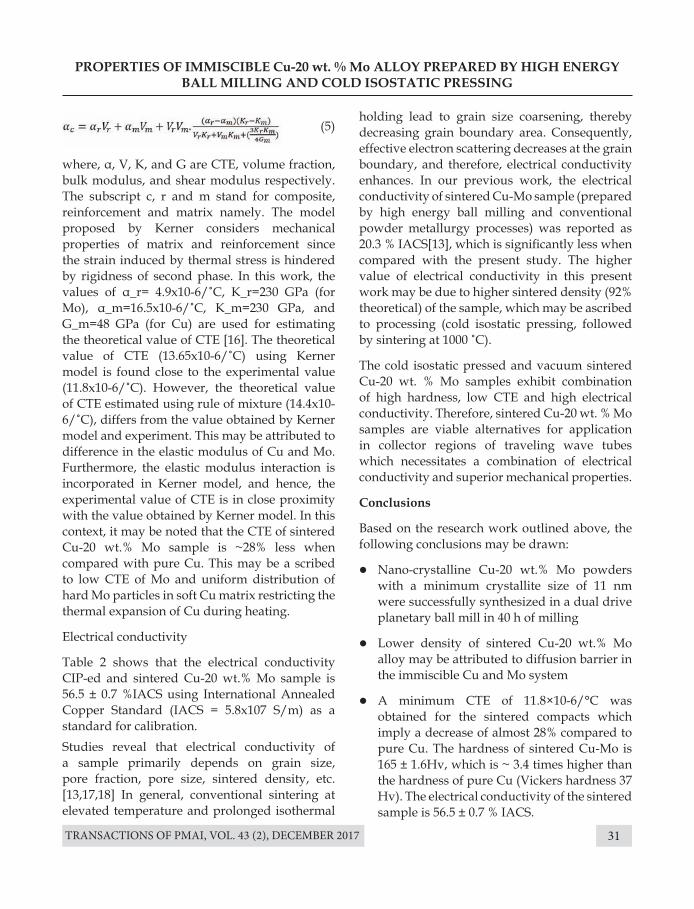
TRANSACTIONS OF PMAI, VOL. 43 (2), DECEMBER 2017 31
where, α, V, K, and G are CTE, volume fraction, bulk modulus, and shear modulus respectively. The subscript c, r and m stand for composite, reinforcement and matrix namely. The model proposed by Kerner considers mechanical properties of matrix and reinforcement since the strain induced by thermal stress is hindered by rigidness of second phase. In this work, the values of α_r= 4.9x10⁻⁶/˚C, K_r=230 GPa (for Mo), α_m=16.5x10⁻⁶/˚C, K_m=230 GPa, and G_m=48 GPa (for Cu) are used for estimating the theoretical value of CTE [16]. The theoretical value of CTE (13.65x10⁻⁶/˚C) using Kerner model is found close to the experimental value (11.8x10⁻⁶/˚C). However, the theoretical value of CTE estimated using rule of mixture (14.4x10⁻⁶/˚C), differs from the value obtained by Kerner model and experiment. This may be attributed to difference in the elastic modulus of Cu and Mo. Furthermore, the elastic modulus interaction is incorporated in Kerner model, and hence, the experimental value of CTE is in close proximity with the value obtained by Kerner model. In this context, it may be noted that the CTE of sintered Cu-20 wt.% Mo sample is ~28% less when compared with pure Cu. This may be a scribed to low CTE of Mo and uniform distribution of hard Mo particles in soft Cu matrix restricting the thermal expansion of Cu during heating.
Electrical conductivity
Table 2 shows that the electrical conductivity CIP-ed and sintered Cu-20 wt.% Mo sample is 56.5 ± 0.7 %IACS using International Annealed Copper Standard (IACS = 5.8x10⁷ S/m) as a standard for calibration. Studies reveal that electrical conductivity of a sample primarily depends on grain size, pore fraction, pore size, sintered density, etc.[13,17,18] In general, conventional sintering at elevated temperature and prolonged isothermal
PROPERTIES OF IMMISCIBLE Cu-20 wt. % Mo ALLOY PREPARED BY HIGH ENERGY BALL MILLING AND COLD ISOSTATIC PRESSING
(5)holding lead to grain size coarsening, thereby decreasing grain boundary area. Consequently, effective electron scattering decreases at the grain boundary, and therefore, electrical conductivity enhances. In our previous work, the electrical conductivity of sintered Cu-Mo sample (prepared by high energy ball milling and conventional powder metallurgy processes) was reported as 20.3 % IACS[13], which is significantly less when compared with the present study. The higher value of electrical conductivity in this present work may be due to higher sintered density (92% theoretical) of the sample, which may be ascribed to processing (cold isostatic pressing, followed by sintering at 1000 ˚C).
The cold isostatic pressed and vacuum sintered Cu-20 wt. % Mo samples exhibit combination of high hardness, low CTE and high electrical conductivity. Therefore, sintered Cu-20 wt. % Mo samples are viable alternatives for application in collector regions of traveling wave tubes which necessitates a combination of electrical conductivity and superior mechanical properties.
Conclusions
Based on the research work outlined above, the following conclusions may be drawn:
l Nano-crystalline Cu-20 wt.% Mo powders with a minimum crystallite size of 11 nm were successfully synthesized in a dual drive planetary ball mill in 40 h of milling
l Lower density of sintered Cu-20 wt.% Mo alloy may be attributed to diffusion barrier in the immiscible Cu and Mo system
l A minimum CTE of 11.8×10⁻⁶/°C was obtained for the sintered compacts which imply a decrease of almost 28% compared to pure Cu. The hardness of sintered Cu-Mo is 165 ± 1.6Hv, which is ~ 3.4 times higher than the hardness of pure Cu (Vickers hardness 37 Hv). The electrical conductivity of the sintered sample is 56.5 ± 0.7 % IACS.
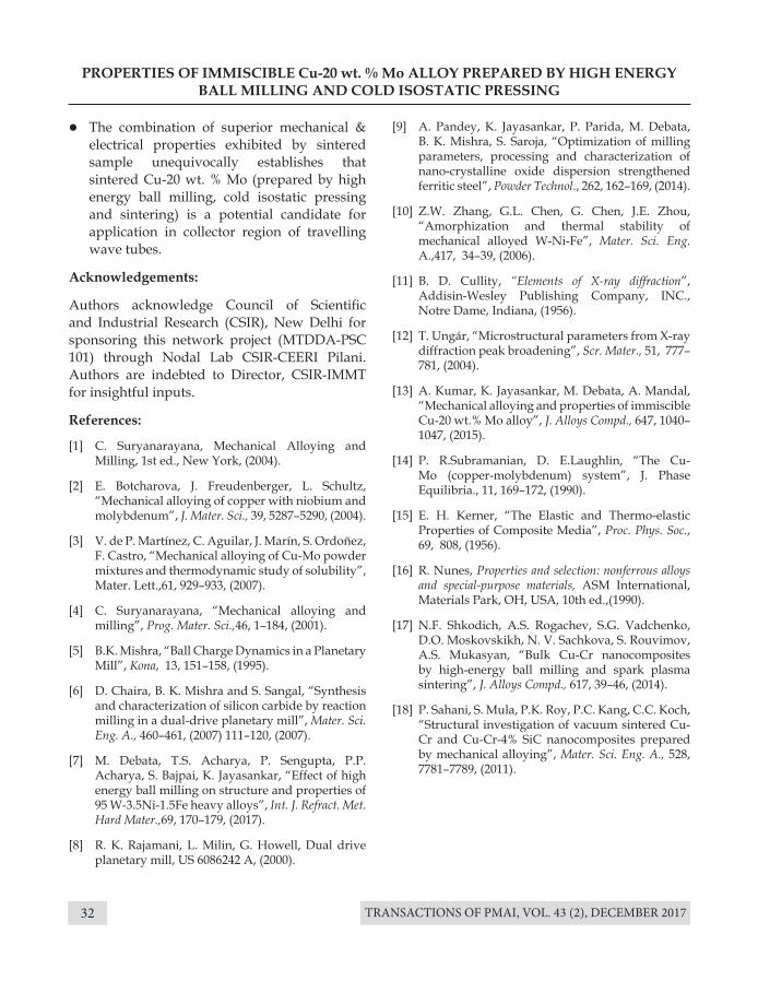
TRANSACTIONS OF PMAI, VOL. 43 (2), DECEMBER 201732
PROPERTIES OF IMMISCIBLE Cu-20 wt. % Mo ALLOY PREPARED BY HIGH ENERGY BALL MILLING AND COLD ISOSTATIC PRESSING
l The combination of superior mechanical & electrical properties exhibited by sintered sample unequivocally establishes that sintered Cu-20 wt. % Mo (prepared by high energy ball milling, cold isostatic pressing and sintering) is a potential candidate for application in collector region of travelling wave tubes.
Acknowledgements:
Authors acknowledge Council of Scientific and Industrial Research (CSIR), New Delhi for sponsoring this network project (MTDDA-PSC 101) through Nodal Lab CSIR-CEERI Pilani. Authors are indebted to Director, CSIR-IMMT for insightful inputs.
References:
[1] C. Suryanarayana, Mechanical Alloying and Milling, 1st ed., New York, (2004).
[2] E. Botcharova, J. Freudenberger, L. Schultz, “Mechanical alloying of copper with niobium and molybdenum”, J. Mater. Sci., 39, 5287–5290, (2004).
[3] V. de P. Martínez, C. Aguilar, J. Marín, S. Ordoñez, F. Castro, “Mechanical alloying of Cu-Mo powder mixtures and thermodynamic study of solubility”, Mater. Lett.,61, 929–933, (2007).
[4] C. Suryanarayana, “Mechanical alloying and milling”, Prog. Mater. Sci.,46, 1–184, (2001).
[5] B.K. Mishra, “Ball Charge Dynamics in a Planetary Mill”, Kona, 13, 151–158, (1995).
[6] D. Chaira, B. K. Mishra and S. Sangal, “Synthesis and characterization of silicon carbide by reaction milling in a dual-drive planetary mill”, Mater. Sci. Eng. A., 460–461, (2007) 111–120, (2007).
[7] M. Debata, T.S. Acharya, P. Sengupta, P.P. Acharya, S. Bajpai, K. Jayasankar, “Effect of high energy ball milling on structure and properties of 95 W-3.5Ni-1.5Fe heavy alloys”, Int. J. Refract. Met. Hard Mater.,69, 170–179, (2017).
[8] R. K. Rajamani, L. Milin, G. Howell, Dual drive planetary mill, US 6086242 A, (2000).
[9] A. Pandey, K. Jayasankar, P. Parida, M. Debata, B. K. Mishra, S. Saroja, “Optimization of milling parameters, processing and characterization of nano-crystalline oxide dispersion strengthened ferritic steel”, Powder Technol., 262, 162–169, (2014).
[10] Z.W. Zhang, G.L. Chen, G. Chen, J.E. Zhou, “Amorphization and thermal stability of mechanical alloyed W-Ni-Fe”, Mater. Sci. Eng. A.,417, 34–39, (2006).
[11] B. D. Cullity, “Elements of X-ray diffraction”, Addisin-Wesley Publishing Company, INC., Notre Dame, Indiana, (1956).
[12] T. Ungár, “Microstructural parameters from X-ray diffraction peak broadening”, Scr. Mater., 51, 777–781, (2004).
[13] A. Kumar, K. Jayasankar, M. Debata, A. Mandal, “Mechanical alloying and properties of immiscible Cu-20 wt.% Mo alloy”, J. Alloys Compd., 647, 1040–1047, (2015).
[14] P. R.Subramanian, D. E.Laughlin, “The Cu-Mo (copper-molybdenum) system”, J. Phase Equilibria., 11, 169–172, (1990).
[15] E. H. Kerner, “The Elastic and Thermo-elastic Properties of Composite Media”, Proc. Phys. Soc., 69, 808, (1956).
[16] R. Nunes, Properties and selection: nonferrous alloys and special-purpose materials, ASM International, Materials Park, OH, USA, 10th ed.,(1990).
[17] N.F. Shkodich, A.S. Rogachev, S.G. Vadchenko, D.O. Moskovskikh, N. V. Sachkova, S. Rouvimov, A.S. Mukasyan, “Bulk Cu-Cr nanocomposites by high-energy ball milling and spark plasma sintering”, J. Alloys Compd., 617, 39–46, (2014).
[18] P. Sahani, S. Mula, P.K. Roy, P.C. Kang, C.C. Koch, “Structural investigation of vacuum sintered Cu-Cr and Cu-Cr-4% SiC nanocomposites prepared by mechanical alloying”, Mater. Sci. Eng. A., 528, 7781–7789, (2011).
TRANSACTIONS OF PMAI, VOL. 43 (2), DECEMBER 2017 33
STRUCTURE PROPERTY CORRELATIONS IN HOT ISOSTATICALLY PRESSED HIGH STRENGTH NICKEL BASE
SUPERALLOY
B. Sreenu a *, Subhradeep Chatterjee b, G. Appa Rao a
a Defence Metallurgical Research Laboratory, Kanchanbagh, Hyderabad, India.b Department of Materials Science & Metallurgical Engineering, IIT, Hyderabad, India.
Introduction
High strength nickel-base superalloys play a vital role in fabrication of aeroengine components operated at high temperature under high stress condition. The superalloys possess good tensile strength, resistance to creep and fatigue at high temperature due to the presence of gamma prime precipitates [γ’: Ni3 (Al, Ti)] which are coherent and remain stable up to relatively high temperature [1]. The superalloys are used in applications at a temperature up to 0.8 Tm (Tm: melting point) and for times of the order of 100,000 h at some what lower temperatures. Based on this advantage, the components like turbine blades, discs, combustion chambers, etc are made out of superalloys [1, 2]. In general, many of these components are manufactured through conventional ingot metallurgy route. However, for an improved engine efficiency, the designers prefer to use highly alloyed materials with increased refractory elements and γ’ volume fraction (>50%). Processing of such high-strength and highly-alloyed materials by conventional route is a challenging task, hence, powder
Abstract : Nickel-base superalloy powder produced by inert gas atomization technique was hot isostatically processed (HIPed) at a selected temperature of 1190±2 °C under 120 MPa pressure for 3 h of sustaining time. The as-HIPed alloy with full density of 8.0 g/cc was characterized for microstructure. The as-HIPed alloy has shown fine equiaxed grains of a varying size with an average grain diameter of 12 μm. The prior particle boundaries (PPBs) occasionally seen in the present alloy are enriched with O, Hf and Zr. The carbides at the grain boundaries are of M23C6 and M3C2 type enriched with Cr. The as- HIPed alloy has exhibited satisfactory levels of strength and ductility at room temperature and at 650°C. The stress rupture properties of as-HIPed alloy exhibited adequate rupture life and ductility 650°C and 750 °C under a varied stress level.
Key words: Hot isostatic pressing, superalloy, prior particle boundaries, grain diameter.
metallurgy (P/M) routes are adopted. The P/M route essentially involves number of steps like powder production, hot isostatic pressing and thermo-mechanical processing [3].
Processing of aeroengine discs by P/M (HIP) + isothermal forging is highly complex, hence, it is essential to understand the microstructure of the material at every stage of processing. For instance, grain size and volume fraction of strengthening phases present in the HIPed billet influence the flow-stress behavior during hot working process [4]. In addition, the prior particle boundaries (PPBs) in the HIPed material also play a crucial role in deformation and achieving the desirable properties in HIP+forged material. Therefore, knowledge about the microstructure and strength of HIPed material is utmost importance before going in for isothermal forging. In the present study, the nickel base superalloy having the gamma prime solvus temperature of about 1190 °C has been processed by P/M HIP route correlated the structure-property relationship in the as-HIPed material.
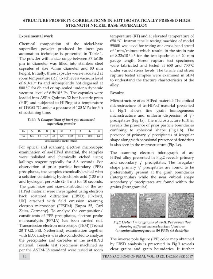
TRANSACTIONS OF PMAI, VOL. 43 (2), DECEMBER 201734
STRUCTURE PROPERTY CORRELATIONS IN HOT ISOSTATICALLY PRESSED HIGH STRENGTH NICKEL BASE SUPERALLOY
Experimental work
Chemical composition of the nickel-base superalloy powder produced by inert gas automation technique is presented in Table-1. The powder with a size range between 37 to106 μm in diameter was filled into stainless steel capsules of size 70mm diameter and 80 mm height. Initially, these capsules were evacuated at room temperature (RT) to achieve a vacuum level of 6.0x10⁻⁴ Pa and subsequently hot degassed at 800 °C for 8h and crimp-sealed under a dynamic vacuum level of 6.5x10⁻⁴ Pa. The capsules were loaded into ASEA Quintus-32 hot isostatic press (HIP) and subjected to HIPing at a temperature of 1190±2 °C under a pressure of 120 MPa for 3 h of sustaining time.
For optical and scanning electron microscopic examination of as-HIPed material, the samples were polished and chemically etched using kallings reagent typically for 5-8 seconds. For observation of prior particle boundary (PPB) precipitates, the samples chemically etched with a solution containing hydrochloric acid (100 ml) and hydrogen peroxide (2- 4 ml) for 10 seconds. The grain size and size-distribution of the as-HIPed material were investigated using electron back scattered diffraction (EBSD) [Oxford, UK] attached with field emission scanning electron microscope (FESEM) [Supra 55, Carl Zeiss, Germany]. To analyse the composition/constituents of PPB precipitates, electron probe microanalysis (EPMA) has been carried out. Transmission electron microscope (TEM) [Tecnai 20 T G2, FEI, Netherland] examination together with EDX analysis was also conducted to analyze the precipitates and carbides in the as-HIPed material. Tensile test specimens machined as per the ASTM-E8 standard were tested at room
The inverse pole figure (IPF) color map obtained by EBSD analysis is presented in Fig.3 reveals clear grains and grain boundaries. It further
Table-1: Composition of inert gas atomized superalloy powder
Fig.1 Optical micrographs of as-HIPed superalloy showing different microstructural features
(a) equiaxedhomogeneous (b) PPBs (c) dendritic
temperature (RT) and at elevated temperature of 650 °C. Instron tensile testing machine of model 5500R was used for testing at a cross-head speed of 1mm/minute which results in the strain rate of 8.33x10⁻⁴ s-1 for the test specimen of 20 mm gauge length. Stress rupture test specimens were fabricated and tested at 650 and 750°C under varied stress levels. The tensile and stress rupture tested samples were examined in SEM to understand the fracture characteristics of the alloy.
Results:
Microstructure of as-HIPed material: The optical microstructure of as-HIPed material presented in Fig.1 shows fine grain homogeneous microstructure and uniform dispersion of γ’-precipitates (Fig.1a). The microstructure further reveals the presence of prior particle boundaries confining to spherical shape (Fig.1.b). The presence of primary γ’ precipitates of irregular shape along with occasional presence of dendrites is also seen in the microstructure (Fig.1.c).
The scanning electron micrograph of as-HIPed alloy presented in Fig.2 reveals primary and secondary γ’ precipitates. The irregular-shape primary γ’ precipitates are found to be preferentially present at the grain boundaries (Intergranular) while the near cubical shape secondary γ’ precipitates are found within the grains (Intragranular).
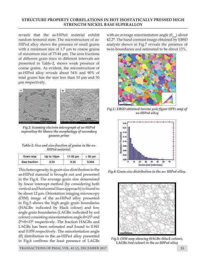
TRANSACTIONS OF PMAI, VOL. 43 (2), DECEMBER 2017 35
STRUCTURE PROPERTY CORRELATIONS IN HOT ISOSTATICALLY PRESSED HIGH STRENGTH NICKEL BASE SUPERALLOY
Fig.2: Scanning electron micrograph of as-HIPed superalloy (b) Shows the morphology of secondary
gamma prime
Fig.3 : EBSD obtained inverse pole figure (IPF) map of as-HIPed alloy
Fig.4: Grain size distribution in the as- HIPed alloy.
Fig.5: OIM map showing HAGBs (black colour), LAGBs (red colour) in the as-HIPed alloy
Table-2: Size and size-fraction of grains in the as-HIPed material.
reveals that the as-HIPed material exhibit random textured state. The microstructure of as-HIPed alloy shows the presence of small grains with a minimum size of 1.7 μm to coarse grains of maximum size of 73.44 μm. The area fractions of different grain sizes in different intervals are presented in Table-2, shows weak presence of coarse grains. As evident, the microstructure of as-HIPed alloy reveals about 54% and 90% of total grains has the size less than 10 μm and 30 μm respectively.
This heterogeneity in grain size distribution in the as-HIPed material is brought out and presented in the Fig.4. The average grain size determined by linear intercept method (by considering both vertical and horizontal lines approach) is found to be about 12 μm. Orientation imaging microscopy (OIM) image of the as-HIPed alloy presented in Fig.5 shows the high angle grain boundaries (HAGBs: indicated by black colour) and low angle grain boundaries (LAGBs: indicated by red colour) consisting misorientation angle θ>15° and 2°<θ<15° respectively. The fraction HAGBs and LAGBs has been estimated and found to 0.941 and 0.059 respectively. The misorientation angle (θ) distribution in the as-HIPed alloy presented in Fig.6 confirms the least presence of LAGBs
with an average misorientation angle (θavg) about 42.2°. The band contrast image obtained by EBSD analysis shown in Fig.7 reveals the presence of twin-boundaries and estimated to be about 15%.
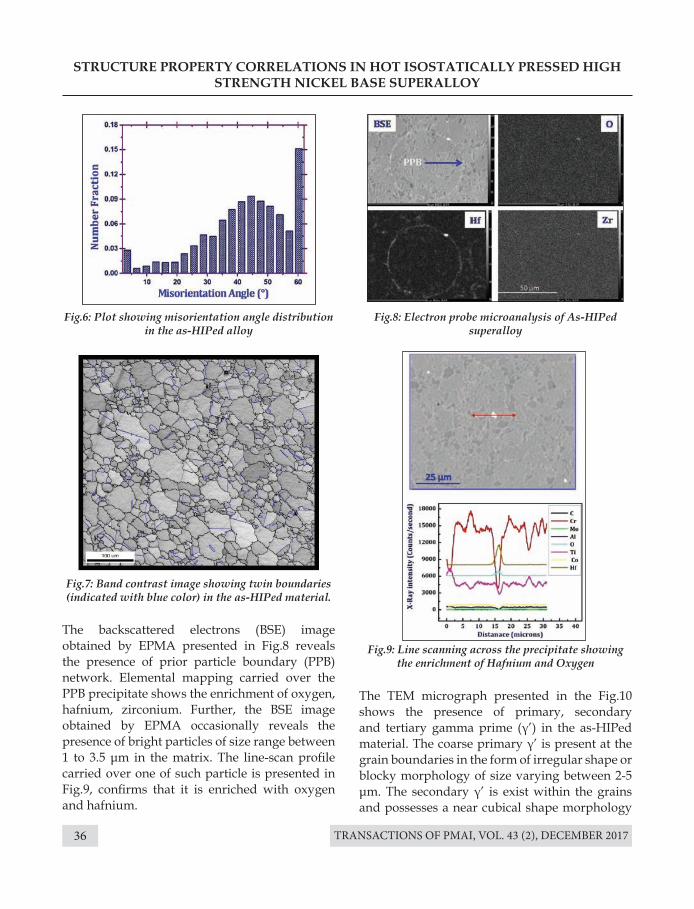
TRANSACTIONS OF PMAI, VOL. 43 (2), DECEMBER 201736
STRUCTURE PROPERTY CORRELATIONS IN HOT ISOSTATICALLY PRESSED HIGH STRENGTH NICKEL BASE SUPERALLOY
Fig.6: Plot showing misorientation angle distribution in the as-HIPed alloy
Fig.8: Electron probe microanalysis of As-HIPed superalloy
Fig.9: Line scanning across the precipitate showing the enrichment of Hafnium and Oxygen
Fig.7: Band contrast image showing twin boundaries(indicated with blue color) in the as-HIPed material.
The backscattered electrons (BSE) image obtained by EPMA presented in Fig.8 reveals the presence of prior particle boundary (PPB) network. Elemental mapping carried over the PPB precipitate shows the enrichment of oxygen, hafnium, zirconium. Further, the BSE image obtained by EPMA occasionally reveals the presence of bright particles of size range between 1 to 3.5 μm in the matrix. The line-scan profile carried over one of such particle is presented in Fig.9, confirms that it is enriched with oxygen and hafnium.
The TEM micrograph presented in the Fig.10 shows the presence of primary, secondary and tertiary gamma prime (γ’) in the as-HIPed material. The coarse primary γ’ is present at the grain boundaries in the form of irregular shape or blocky morphology of size varying between 2-5 μm. The secondary γ’ is exist within the grains and possesses a near cubical shape morphology
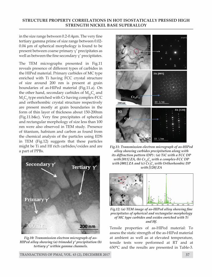
TRANSACTIONS OF PMAI, VOL. 43 (2), DECEMBER 2017 37
STRUCTURE PROPERTY CORRELATIONS IN HOT ISOSTATICALLY PRESSED HIGH STRENGTH NICKEL BASE SUPERALLOY
Fig.10: Transmission electron micrograph of as-HIPed alloy showing (a) trimodal γ′ precipitation (b)
tertiary γ′ within gamma channels.
Fig.11: Transmission electron micrograph of as-HIPed alloy showing carbides precipitation along with
its diffraction pattern (DP) : (a) TiC with a FCC DP with [011] ZA, (b) Cr23C6 with a complex-FCC DP
with [001] ZA and (c) Cr3C2 with Orthorhombic DP with [120] ZA
Fig.12: (a) TEM image of as-HIPed alloy showing fine precipitates of spherical and rectangular morphology
of MC type carbides and oxides enriched with Ti and Hf.
in the size range between 0.2-0.4μm. The very fine tertiary gamma prime of size range between 0.02-0.04 μm of spherical morphology is found to be present between coarse primary γ’ precipitates as well as between the fine secondary γ’ precipitates.
The TEM micrographs presented in Fig.11 reveals presence of different types of carbides in the HIPed material. Primary carbides of MC type enriched with Ti having FCC crystal structure of size around 200 nm is present at grain boundaries of as-HIPed material (Fig.11.a). On the other hand, secondary carbides of M23C6 and M3C2 type enriched with Cr having complex-FCC and orthorhombic crystal structure respectively are present mostly at grain boundaries in the form of thin layer of thickness about 150-200nm (Fig.11.b&c). Very fine precipitates of spherical and rectangular morphology of size less than 100 nm were also observed in TEM study. Presence of titanium, hafnium and carbon as found from the chemical analysis of the particles using EDS in TEM (Fig.12) suggests that these particles might be Ti and Hf rich carbides/oxides and are a part of PPBs.
Tensile properties of as-HIPed material: To assess the static strength of the as-HIPed material at ambient as well as at elevated temperature, tensile tests were performed at RT and at 650°C and the results are presented in Table-3.
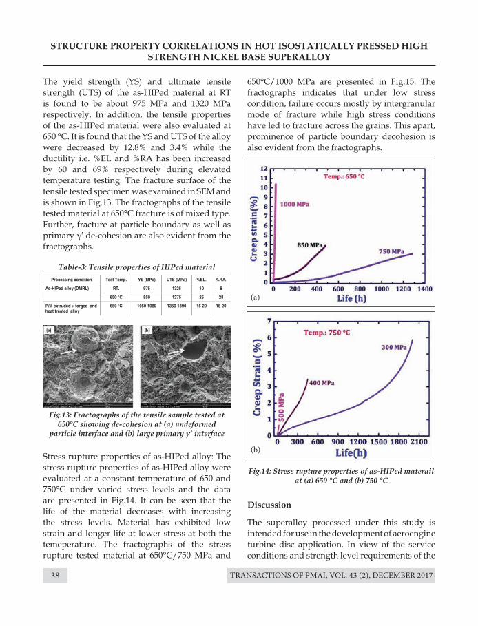
TRANSACTIONS OF PMAI, VOL. 43 (2), DECEMBER 201738
The yield strength (YS) and ultimate tensile strength (UTS) of the as-HIPed material at RT is found to be about 975 MPa and 1320 MPa respectively. In addition, the tensile properties of the as-HIPed material were also evaluated at 650 °C. It is found that the YS and UTS of the alloy were decreased by 12.8% and 3.4% while the ductility i.e. %EL and %RA has been increased by 60 and 69% respectively during elevated temperature testing. The fracture surface of the tensile tested specimen was examined in SEM and is shown in Fig.13. The fractographs of the tensile tested material at 650°C fracture is of mixed type. Further, fracture at particle boundary as well as primary γ′ de-cohesion are also evident from the fractographs.
Stress rupture properties of as-HIPed alloy: The stress rupture properties of as-HIPed alloy were evaluated at a constant temperature of 650 and 750°C under varied stress levels and the data are presented in Fig.14. It can be seen that the life of the material decreases with increasing the stress levels. Material has exhibited low strain and longer life at lower stress at both the temeperature. The fractographs of the stress rupture tested material at 650°C/750 MPa and
STRUCTURE PROPERTY CORRELATIONS IN HOT ISOSTATICALLY PRESSED HIGH STRENGTH NICKEL BASE SUPERALLOY
Table-3: Tensile properties of HIPed material
Fig.14: Stress rupture properties of as-HIPed materail at (a) 650 °C and (b) 750 °C
Fig.13: Fractographs of the tensile sample tested at 650°C showing de-cohesion at (a) undeformed
particle interface and (b) large primary γ’ interface
650°C/1000 MPa are presented in Fig.15. The fractographs indicates that under low stress condition, failure occurs mostly by intergranular mode of fracture while high stress conditions have led to fracture across the grains. This apart, prominence of particle boundary decohesion is also evident from the fractographs.
Discussion
The superalloy processed under this study is intended for use in the development of aeroengine turbine disc application. In view of the service conditions and strength level requirements of the
(a)
(b)
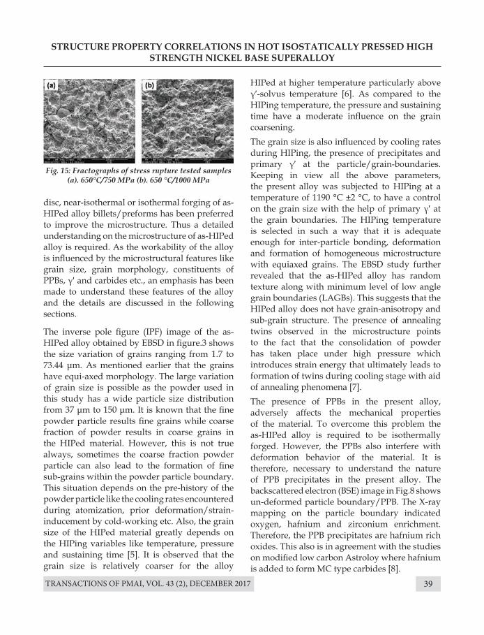
TRANSACTIONS OF PMAI, VOL. 43 (2), DECEMBER 2017 39
STRUCTURE PROPERTY CORRELATIONS IN HOT ISOSTATICALLY PRESSED HIGH STRENGTH NICKEL BASE SUPERALLOY
Fig. 15: Fractographs of stress rupture tested samples (a). 650°C/750 MPa (b). 650 °C/1000 MPa
disc, near-isothermal or isothermal forging of as- HIPed alloy billets/preforms has been preferred to improve the microstructure. Thus a detailed understanding on the microstructure of as-HIPed alloy is required. As the workability of the alloy is influenced by the microstructural features like grain size, grain morphology, constituents of PPBs, γ′ and carbides etc., an emphasis has been made to understand these features of the alloy and the details are discussed in the following sections.
The inverse pole figure (IPF) image of the as-HIPed alloy obtained by EBSD in figure.3 shows the size variation of grains ranging from 1.7 to 73.44 μm. As mentioned earlier that the grains have equi-axed morphology. The large variation of grain size is possible as the powder used in this study has a wide particle size distribution from 37 μm to 150 μm. It is known that the fine powder particle results fine grains while coarse fraction of powder results in coarse grains in the HIPed material. However, this is not true always, sometimes the coarse fraction powder particle can also lead to the formation of fine sub-grains within the powder particle boundary. This situation depends on the pre-history of the powder particle like the cooling rates encountered during atomization, prior deformation/strain-inducement by cold-working etc. Also, the grain size of the HIPed material greatly depends on the HIPing variables like temperature, pressure and sustaining time [5]. It is observed that the grain size is relatively coarser for the alloy
HIPed at higher temperature particularly above γ′-solvus temperature [6]. As compared to the HIPing temperature, the pressure and sustaining time have a moderate influence on the grain coarsening.The grain size is also influenced by cooling rates during HIPing, the presence of precipitates and primary γ′ at the particle/grain-boundaries. Keeping in view all the above parameters, the present alloy was subjected to HIPing at a temperature of 1190 °C ±2 °C, to have a control on the grain size with the help of primary γ′ at the grain boundaries. The HIPing temperature is selected in such a way that it is adequate enough for inter-particle bonding, deformation and formation of homogeneous microstructure with equiaxed grains. The EBSD study further revealed that the as-HIPed alloy has random texture along with minimum level of low angle grain boundaries (LAGBs). This suggests that the HIPed alloy does not have grain-anisotropy and sub-grain structure. The presence of annealing twins observed in the microstructure points to the fact that the consolidation of powder has taken place under high pressure which introduces strain energy that ultimately leads to formation of twins during cooling stage with aid of annealing phenomena [7].The presence of PPBs in the present alloy, adversely affects the mechanical properties of the material. To overcome this problem the as-HIPed alloy is required to be isothermally forged. However, the PPBs also interfere with deformation behavior of the material. It is therefore, necessary to understand the nature of PPB precipitates in the present alloy. The backscattered electron (BSE) image in Fig.8 shows un-deformed particle boundary/PPB. The X-ray mapping on the particle boundary indicated oxygen, hafnium and zirconium enrichment. Therefore, the PPB precipitates are hafnium rich oxides. This also is in agreement with the studies on modified low carbon Astroloy where hafnium is added to form MC type carbides [8].
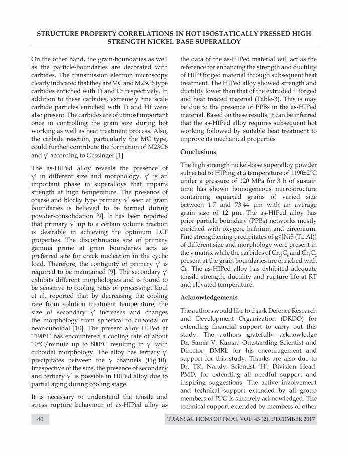
TRANSACTIONS OF PMAI, VOL. 43 (2), DECEMBER 201740
STRUCTURE PROPERTY CORRELATIONS IN HOT ISOSTATICALLY PRESSED HIGH STRENGTH NICKEL BASE SUPERALLOY
On the other hand, the grain-boundaries as well as the particle-boundaries are decorated with carbides. The transmission electron microscopy clearly indicated that they are MC and M23C6 type carbides enriched with Ti and Cr respectively. In addition to these carbides, extremely fine scale carbide particles enriched with Ti and Hf were also present. The carbides are of utmost important once in controlling the grain size during hot working as well as heat treatment process. Also, the carbide reaction, particularly the MC type, could further contribute the formation of M23C6 and γ’ according to Gessinger [1]
The as-HIPed alloy reveals the presence of γ’ in different size and morphology. γ’ is an important phase in superalloys that imparts strength at high temperature. The presence of coarse and blocky type primary γ’ seen at grain boundaries is believed to be formed during powder-consolidation [9]. It has been reported that primary γ’ up to a certain volume fraction is desirable in achieving the optimum LCF properties. The discontinuous site of primary gamma prime at grain boundaries acts as preferred site for crack nucleation in the cyclic load. Therefore, the contiguity of primary γ’ is required to be maintained [9]. The secondary γ’ exhibits different morphologies and is found to be sensitive to cooling rates of processing. Koul et al. reported that by decreasing the cooling rate from solution treatment temperature, the size of secondary γ′ increases and changes the morphology from spherical to cuboidal or near-cuboidal [10]. The present alloy HIPed at 1190°C has encountered a cooling rate of about 10°C/minute up to 800°C resulting in γ’ with cuboidal morphology. The alloy has tertiary γ’ precipitates between the γ channels (Fig.10). Irrespective of the size, the presence of secondary and tertiary γ’ is possible in HIPed alloy due to partial aging during cooling stage.
It is necessary to understand the tensile and stress rupture behaviour of as-HIPed alloy as
the data of the as-HIPed material will act as the reference for enhancing the strength and ductility of HIP+forged material through subsequent heat treatment. The HIPed alloy showed strength and ductility lower than that of the extruded + forged and heat treated material (Table-3). This is may be due to the presence of PPBs in the as-HIPed material. Based on these results, it can be inferred that the as-HIPed alloy requires subsequent hot working followed by suitable heat treatment to improve its mechanical properties
Conclusions
The high strength nickel-base superalloy powder subjected to HIPing at a temperature of 1190±2°C under a pressure of 120 MPa for 3 h of sustain time has shown homogeneous microstructure containing equiaxed grains of varied size between 1.7 and 73.44 μm with an average grain size of 12 μm. The as-HIPed alloy has prior particle boundary (PPBs) networks mostly enriched with oxygen, hafnium and zirconium. Fine strengthening precipitates of g¢[Ni3 (Ti, Al)] of different size and morphology were present in the γ matrix while the carbides of Cr23C6 and Cr3C2 present at the grain boundaries are enriched with Cr. The as-HIPed alloy has exhibited adequate tensile strength, ductility and rupture life at RT and elevated temperature.
Acknowledgements
The authors would like to thank Defence Research and Development Organization (DRDO) for extending financial support to carry out this study. The authors gratefully acknowledge Dr. Samir V. Kamat, Outstanding Scientist and Director, DMRL for his encouragement and support for this study. Thanks are also due to Dr. TK. Nandy, Scientist ‘H’, Division Head, PMD, for extending all needful support and inspiring suggestions. The active involvement and technical support extended by all group members of PPG is sincerely acknowledged. The technical support extended by members of other
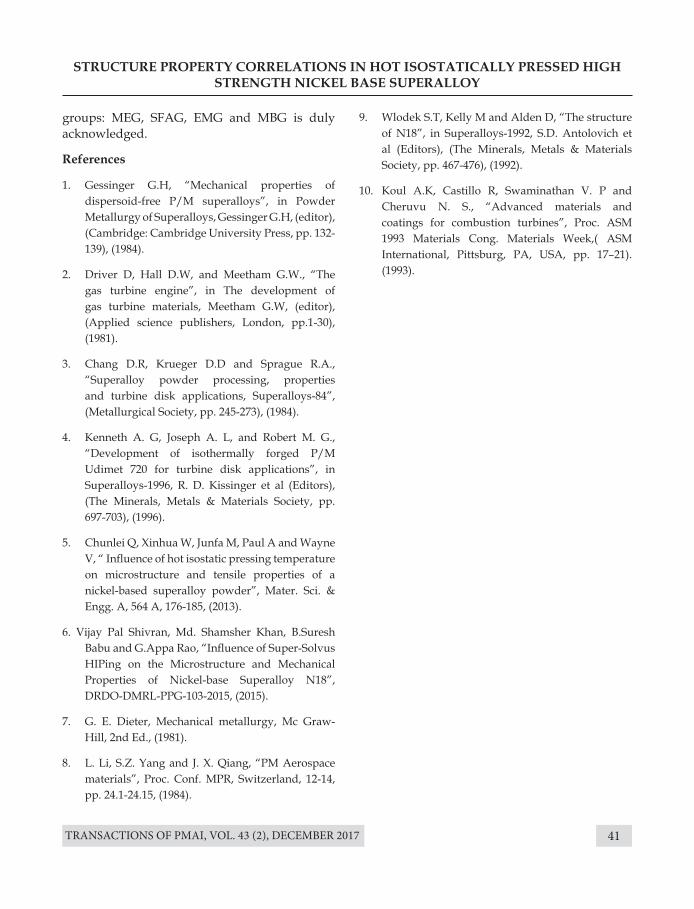
TRANSACTIONS OF PMAI, VOL. 43 (2), DECEMBER 2017 41
STRUCTURE PROPERTY CORRELATIONS IN HOT ISOSTATICALLY PRESSED HIGH STRENGTH NICKEL BASE SUPERALLOY
groups: MEG, SFAG, EMG and MBG is duly acknowledged.
References
1. Gessinger G.H, “Mechanical properties of dispersoid-free P/M superalloys”, in Powder Metallurgy of Superalloys, Gessinger G.H, (editor), (Cambridge: Cambridge University Press, pp. 132-139), (1984).
2. Driver D, Hall D.W, and Meetham G.W., “The gas turbine engine”, in The development of gas turbine materials, Meetham G.W, (editor), (Applied science publishers, London, pp.1-30), (1981).
3. Chang D.R, Krueger D.D and Sprague R.A., “Superalloy powder processing, properties and turbine disk applications, Superalloys-84”, (Metallurgical Society, pp. 245-273), (1984).
4. Kenneth A. G, Joseph A. L, and Robert M. G., “Development of isothermally forged P/M Udimet 720 for turbine disk applications”, in Superalloys-1996, R. D. Kissinger et al (Editors), (The Minerals, Metals & Materials Society, pp. 697-703), (1996).
5. Chunlei Q, Xinhua W, Junfa M, Paul A and Wayne V, “ Influence of hot isostatic pressing temperature on microstructure and tensile properties of a nickel-based superalloy powder”, Mater. Sci. & Engg. A, 564 A, 176-185, (2013).
6. Vijay Pal Shivran, Md. Shamsher Khan, B.Suresh Babu and G.Appa Rao, “Influence of Super-Solvus HIPing on the Microstructure and Mechanical Properties of Nickel-base Superalloy N18”, DRDO-DMRL-PPG-103-2015, (2015).
7. G. E. Dieter, Mechanical metallurgy, Mc Graw-Hill, 2nd Ed., (1981).
8. L. Li, S.Z. Yang and J. X. Qiang, “PM Aerospace materials”, Proc. Conf. MPR, Switzerland, 12-14, pp. 24.1-24.15, (1984).
9. Wlodek S.T, Kelly M and Alden D, “The structure of N18”, in Superalloys-1992, S.D. Antolovich et al (Editors), (The Minerals, Metals & Materials Society, pp. 467-476), (1992).
10. Koul A.K, Castillo R, Swaminathan V. P and Cheruvu N. S., “Advanced materials and coatings for combustion turbines”, Proc. ASM 1993 Materials Cong. Materials Week,( ASM International, Pittsburg, PA, USA, pp. 17–21). (1993).
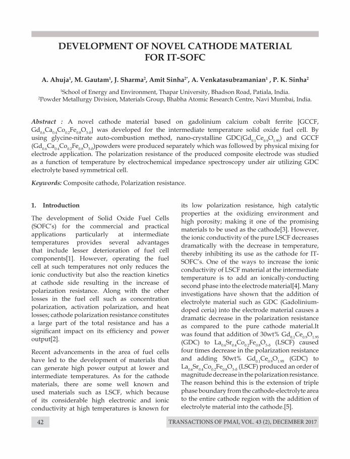
TRANSACTIONS OF PMAI, VOL. 43 (2), DECEMBER 201742
DEVELOPMENT OF NOVEL CATHODE MATERIAL FOR IT-SOFC
A. Ahuja1, M. Gautam1, J. Sharma2, Amit Sinha2*, A. Venkatasubramanian1 , P. K. Sinha2
1School of Energy and Environment, Thapar University, Bhadson Road, Patiala, India. 2Powder Metallurgy Division, Materials Group, Bhabha Atomic Research Centre, Navi Mumbai, India.
1. Introduction
The development of Solid Oxide Fuel Cells (SOFC’s) for the commercial and practical applications particularly at intermediate temperatures provides several advantages that include lesser deterioration of fuel cell components[1]. However, operating the fuel cell at such temperatures not only reduces the ionic conductivity but also the reaction kinetics at cathode side resulting in the increase of polarization resistance. Along with the other losses in the fuel cell such as concentration polarization, activation polarization, and heat losses; cathode polarization resistance constitutes a large part of the total resistance and has a significant impact on its efficiency and power output[2].
Recent advancements in the area of fuel cells have led to the development of materials that can generate high power output at lower and intermediate temperatures. As for the cathode materials, there are some well known and used materials such as LSCF, which because of its considerable high electronic and ionic conductivity at high temperatures is known for
Abstract : A novel cathode material based on gadolinium calcium cobalt ferrite [GCCF, Gd0.6Ca0.4Co0.2Fe0.8O3-δ] was developed for the intermediate temperature solid oxide fuel cell. By using glycine-nitrate auto-combustion method, nano-crystalline GDC(Gd0.1Ce0.9O1.95) and GCCF (Gd0.6Ca0.4Co0.2Fe0.8O3-δ)powders were produced separately which was followed by physical mixing for electrode application. The polarization resistance of the produced composite electrode was studied as a function of temperature by electrochemical impedance spectroscopy under air utilizing GDC electrolyte based symmetrical cell.
Keywords: Composite cathode, Polarization resistance.
its low polarization resistance, high catalytic properties at the oxidizing environment and high porosity; making it one of the promising materials to be used as the cathode[3]. However, the ionic conductivity of the pure LSCF decreases dramatically with the decrease in temperature, thereby inhibiting its use as the cathode for IT-SOFC’s. One of the ways to increase the ionic conductivity of LSCF material at the intermediate temperature is to add an ionically-conducting second phase into the electrode material[4]. Many investigations have shown that the addition of electrolyte material such as GDC (Gadolinium-doped ceria) into the electrode material causes a dramatic decrease in the polarization resistance as compared to the pure cathode material.It was found that addition of 30wt% Gd0.1Ce0.9O1.95 (GDC) to La0.6Sr0.4Co0.2Fe0.8O3-δ (LSCF) caused four times decrease in the polarization resistance and adding 50wt% Gd0.1Ce0.9O1.95 (GDC) to La0.6Sr0.4Co0.2Fe0.8O3-δ (LSCF) produced an order of magnitude decrease in the polarization resistance. The reason behind this is the extension of triple phase boundary from the cathode-electrolyte area to the entire cathode region with the addition of electrolyte material into the cathode.[5].
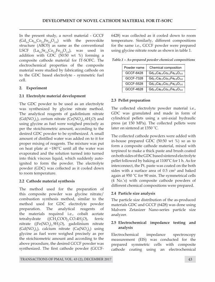
TRANSACTIONS OF PMAI, VOL. 43 (2), DECEMBER 2017 43
DEVELOPMENT OF NOVEL CATHODE MATERIAL FOR IT-SOFC
In the present study, a novel material - GCCF (Gd0.6Ca0.4Co0.2Fe0.8O3-δ) with the perovskite structure (ABO3) as same as the conventional LSCF (La0.6Sr0.4Co0.2Fe0.8O3-δ), was used in addition with GDC (50:50 wt %) forming a composite cathode material for IT-SOFC. The electrochemical properties of the composite material were studied by fabricating cathode on to the GDC based electrolyte - symmetric fuel cell.
2. Experiment
2.1 Electrolyte material development
The GDC powder to be used as an electrolyte was synthesized by glycine nitrate method. The analytical reagents of gadolinium nitrate (Gd(NO3)3), cerium nitrate (Ce(NO3)3.6H2O) and using glycine as fuel were weighed precisely as per the stoichiometric amount, according to the desired GDC powder to be synthesized. A small amount of distilled water was added on to it for proper mixing of reagents. The mixture was put on heat plate at ~180˚C until all the water was evaporated and the solution turned into turned into thick viscous liquid, which suddenly auto-ignited to form the powder. The electrolyte powder (GDC) was collected as it cooled down to room temperature.
2.2 Cathode material synthesis
The method used for the preparation of this composite powder was glycine nitrate/combustion synthesis method, similar to the method used for GDC electrolyte powder preparation. The analytical reagents of the materials required i.e., cobalt acetate tetrahydrate ((CH3COO)2.CO.4H2O), ferric nitrate ((Fe(NO3)3.9H2O), gadolinium nitrate (Gd(NO3)3), calcium nitrate (Ca(NO3)2) using glycine as fuel were weighed precisely as per the stoichiometric amount and according to the above procedure, the desired GCCF powder was synthesized. The first cathode powder (GCCF-
6428) was collected as it cooled down to room temperature. Similarly, different compositions for the same i.e., GCCF powder were prepared using glycine nitrate route as shown in table 1.
2.3 Pellet preparation
The collected electrolyte powder material i.e., GDC was granulated and made in form of cylindrical pellets using a uni-axial hydraulic press (at 150 MPa). The collected pellets were later on sintered at 1350 ˚C.
The collected cathode powders were added with in-house prepared GDC (50:50 wt %) so as to form a composite cathode material, mixed with terpineol to make a thick paste and brush coated on both sides of the GDC based sintered electrolyte pellet followed by baking at 1100˚C for 1 h. As for interconnect, the Pt. paste was coated on the both sides with a surface area of 0.5 cm2 and baked again at 950 ˚C for 90 min. The symmetrical cells (4 No.’s) with composite cathode powders of different chemical compositions were prepared.
2.4 Particle size analysis The particle size distribution of the as-produced materials GDC and GCCF (6428) was done using Malvern Zetasizer Nano-series particle size analyzer.
2.5 Electrochemical impedance testing and analysis
Electrochemical impedance spectroscopy measurement (EIS) was conducted for the prepared symmetric cells with composite cathode coating using an electrochemical
Table.1 – As-prepared powder chemical compositions
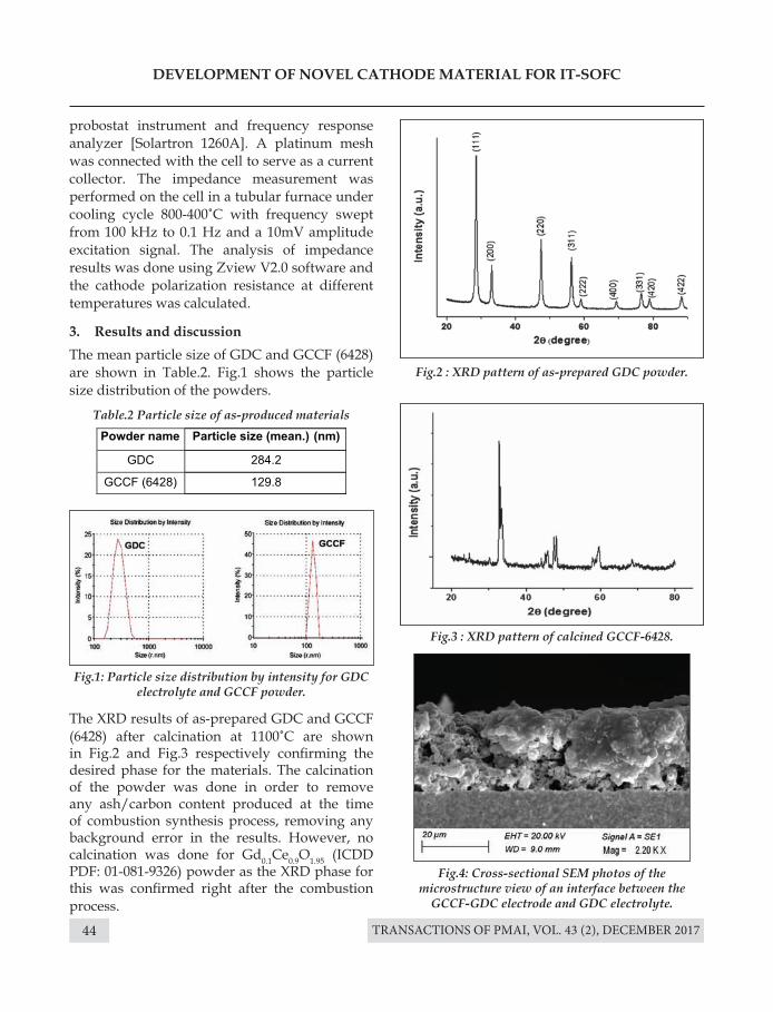
TRANSACTIONS OF PMAI, VOL. 43 (2), DECEMBER 201744
DEVELOPMENT OF NOVEL CATHODE MATERIAL FOR IT-SOFC
probostat instrument and frequency response analyzer [Solartron 1260A]. A platinum mesh was connected with the cell to serve as a current collector. The impedance measurement was performed on the cell in a tubular furnace under cooling cycle 800-400˚C with frequency swept from 100 kHz to 0.1 Hz and a 10mV amplitude excitation signal. The analysis of impedance results was done using Zview V2.0 software and the cathode polarization resistance at different temperatures was calculated.
3. Results and discussionThe mean particle size of GDC and GCCF (6428) are shown in Table.2. Fig.1 shows the particle size distribution of the powders.
The XRD results of as-prepared GDC and GCCF (6428) after calcination at 1100˚C are shown in Fig.2 and Fig.3 respectively confirming the desired phase for the materials. The calcination of the powder was done in order to remove any ash/carbon content produced at the time of combustion synthesis process, removing any background error in the results. However, no calcination was done for Gd0.1Ce0.9O1.95 (ICDD PDF: 01-081-9326) powder as the XRD phase for this was confirmed right after the combustion process.
Table.2 Particle size of as-produced materials
Fig.1: Particle size distribution by intensity for GDC electrolyte and GCCF powder.
Fig.2 : XRD pattern of as-prepared GDC powder.
Fig.3 : XRD pattern of calcined GCCF-6428.
Fig.4: Cross-sectional SEM photos of the microstructure view of an interface between the
GCCF-GDC electrode and GDC electrolyte.
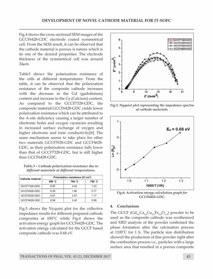
TRANSACTIONS OF PMAI, VOL. 43 (2), DECEMBER 2017 45
DEVELOPMENT OF NOVEL CATHODE MATERIAL FOR IT-SOFC
Fig.4 shows the cross-sectional SEM images of the GCCF6428-GDC electrode coated symmetrical cell. From the SEM result, it can be observed that the cathode material is porous is nature which is its one of the desired properties. The electrode thickness of the symmetrical cell was around 24µm.
4. ConclusionsThe GCCF (Gd0.6Ca0.4Co0.2Fe0.8O3-δ) powder to be used as the composite cathode was synthesized and XRD analysis of the powder confirmed the phase formation after the calcination process at 1100˚C for 1 h. The particle size distribution showed the production of fine powder right after the combustion process i.e., particles with a large surface area that resulted in a porous composite
Table3 shows the polarization resistance of the cells at different temperatures. From the table, it can be observed that the polarization resistance of the composite cathode increases with the decrease in the Gd (gadolinium) content and increase in the Ca (Calcium) content. As compared to the GCCF7328-GDC, the composite material GCCF6428-GDC yields lower polarization resistance which can be attributed to the A-site deficiency causing a larger number of electronic holes and oxygen vacancies resulting in increased surface exchange of oxygen and higher electronic and ionic conductivity[6]. The same mechanism seems to take place for other two materials GCCF5528-GDC and GCCF4628-GDC, as their polarization resistance falls lower than that of GCCF7328-GDC, but is still higher than GCCF6428-GDC.
Fig.5 shows the Nyquist plot for the collective impedance results for different prepared cathode composites at 650˚C while Fig.6 shows the activation energy graph for GCCF6428-GDC. The activation energy calculated for the GCCF based composite cathode was 0.68 eV.
Fig.5: Nyquist plot representing the impedance spectra of cathode materials.
Fig.6: Activation energy calculation graph for GCCF6428-GDC.
Table.3 – Cathode polarization resistance due to different materials at different temperatures.
TRANSACTIONS OF PMAI, VOL. 43 (2), DECEMBER 201746
DEVELOPMENT OF NOVEL CATHODE MATERIAL FOR IT-SOFC
cathode when mixed with the GDC powder. The polarization resistance of the symmetrical cell coated with GCCF(6428)-GDC was comparable to that of the GDC electrolyte symmetric cell coated with in-house prepared LSCF-GDC (CS). The activation energy for the composite cathode GCCF(6428)-GDC was 0.68 eV, which is significantly lesser than the in-house prepared LSCF(6428)-GDC with an activation energy of 1.34 eV.
AcknowledgementThe authors wish to thank, Dr. J. Kolte of IIT, Bombay for XRD analysis and Dr. P. K. Patro of Powder Metallurgy Division, BARC for SEM analysis.
References[1] J. Molenda, K. Swierczek, and W. Zaj, “Functional
materials for the IT-SOFC,” vol. 173,657–670, (2007).
[2] S. C. Singhal and K. Kendall, “High Temperature and Solid Oxide Fuel Cells,” High Temp. Solid Oxide Fuel Cells, 1–22, (2003).
[3] A. Dutta, J. Mukhopadhyay, and R. N. Basu, “Combustion synthesis and characterization of LSCF-based materials as cathode of intermediate temperature solid oxide fuel cells,” J. Eu. Cer. Soc., 29 (10), 2003–2011, (2009).
[4] H. Jin, J. Moon, S. Lee, and E. A. Lee, “Electrochemical performance of LSCF-based composite cathodes for intermediate temperature SOFCs,” J. Power Sources, 145 (2), 243–248, (2005).
[5] Y. Leng, S. H. Chan, and Q. Liu, “Development of LSCF-GDC composite cathodes for low-temperature solid oxide fuel cells with thin film GDC electrolyte,” Int. J. Hydrogen Energy, 33 (14), 3808–3817, (2008).
[6] F. Qiang, K. Sun, N. Zhang, X. Zhu, S. Le, and D. Zhou, “Characterization of electrical properties of GDC doped A-site deficient LSCF based composite cathode using impedance spectroscopy,” J. Power Sources, 168 (2), 338–345, (2007).
TRANSACTIONS OF PMAI, VOL. 43 (2), DECEMBER 2017 47
SYNTHESIS OF ULTRA-HIGH TEMPERATURE CERAMIC COATINGON NIOBIUM ALLOYBY REACTIVE SPARK
PLASMA SINTERINGManoj Hajare, N. S. Karthiselva, T. Venkateswaran1, Srinivasa R. Bakshi*
Department of Metallurgical and Materials Engineering, IIT, Madras, Chennai, India. 1Vikram Sarabhai Space Centre, Thiruvananthapuramm, India.
*Corresponding Author Email: [email protected]
Introduction
Niobium (Nb), a group VB ductile transition metal and Nb-base alloys (C-103) as high temperature material is prime candidate for high temperature nuclear reactors as well as for aerospace applications because of its high melting point (2477oC), high temperatures strength, irradiation damage resistance, high temperature liquid metal corrosion resistance[1][2]. Niobium alloys are most suitable structural materials in the temperature range between 900 and 1200oC. However, a major barrier to their practical applications at higher temperature is its severe degradation because of the poor oxidation resistance. This may be due to the fact that Nb itself oxidizes rapidly, forming a non-protective oxide scale[1]. This disastrous oxidation of pure Nb and Nb alloys limits their practical applications at high temperatures[3]. Efforts to improve the oxidation resistance through variations in alloys have encouraged improvements, but to the impairment of their mechanical properties. Also, the improvement by alloying is not enough
Abstract : In order to protect Niobium Alloy(C-103) from oxidation, coatings of Ultra-High Temperature Ceramic (UHTCs) ZrB2 and ZrB2-20 vol.% SiC (ZS)were prepared in situ on the Niobium Alloy(C-103) substrate by Reactive Spark Plasma Sintering (RSPS) at a temperature of 1400°Cusing ball milled elemental powders and SiC. This is the lowest temperature used for preparing such a coating. The low temperature synthesis of ZrB2 and ZS coating by RSPS prevented Nb substrate from very high temperature exposure during processing. The microstructural and phaseevolution and the composition across the interface were investigated by scanning electron microscopy, energy dispersive spectroscopy and X-ray diffraction. The thick and dense layer synthesized had suitably strong bond strength with a better interface. No micro-cracking was observed at the interface.
Keywords: Nb alloy (C-103), UHTC Coating, Reactive Spark Plasma Sintering (RSPS).
for actual high-temperature applications in oxidizing environments. It is now generally recognized that deposition of coatings that can form dense, adherent and slow-growing oxide scales offer the most promising approach to improving long term environmental stability at high-temperatures[4].
Many studies have focused on silicon as the coating materials for Nb based high temperature alloys by pack cementation, hot dipping, molten salt, and slurry method[4][5][6][7].However, these coating processes require a long reaction time and the coefficient of thermal expansion (CTE) of SiO2 is quite different from that of NbSi2, this would cause extensive oxide cracking or spalling during oxidation process at intermediate temperature range of 1200-1400°C[3][8]. Hence, to extend the practical application of Nb alloy at higher temperature, it is necessary to coat or join it with Ultra-High Temperature Ceramics (UHTCs)
UHTCs have been identified as a class of materials with the potential to withstand
TRANSACTIONS OF PMAI, VOL. 43 (2), DECEMBER 201748
SYNTHESIS OF ULTRA-HIGH TEMPERATURE CERAMIC COATINGON NIOBIUM ALLOYBY REACTIVE SPARK PLASMA SINTERING
extreme aerothermal heating environments. For example, diboride and carbide based ceramics which possess melting temperatures in excess of 3000°C. Few of the most regularly used and studied UHTCs with their melting point are SiC (2730°C), ZrB2 (3200°C), HfB2 (3250°C), HfC (3890°C), ZrC (3530°C). Currently, the ultra-high temperature ceramic ZrB2 is being actively investigated as an aerospace material to withstand the severe environment due to its excellent properties, such as high melting point, high thermal conductivity and excellent chemical and physical stability at high temperature with a ability to form refractory oxide scale to withstand temperatures in the range of 1900-2500oC[10][11]. Mostly, Silicon Carbide (SiC) is added in ZrB2 to further enhance oxidation resistance and limit diboride grain growth.
In the last decade, several investigations have been conducted on UHTC/metal joining process like dense interlayer, intermediate metal foam layer[9][12][13]. Indeed, metal foams have been used as buffer layers in ceramic/metal brazing[9][14][15]. However, the bonding between foam and substrate needs brazing, which causes large stress concentration during melting–solidification process due to mismatch of coefficient of thermal expansion (CTE). Additionally, liquid filler alloy during brazing leads to severe interfacial reactions which result in complex joint structure and produce various intermetallic compounds, and subsequently harms the joint strength. Also, the joints have comparatively low stiffness and strength due to the high porosity of foams, which is not suitable to apply in practice.
In view of the above problems, diffusion bonding which depends on solid state diffusion can eliminates the problems of segregation, solidification cracking, and over-interfacial reactions usually found in brazing process[10][16]. However, it requires a combination of high temperature and pressure to obtain an intimate contact, and relatively long time to ensure
sufficient mutual diffusion by conventional methods like hot pressing process. This exposure of Nb substrate to high temperature for long duration during synthesis and coating of ZrB2 and ZS by conventional method will severely affect its properties. Reactive Spark Plasma Sintering (RSPS) can be effectively used to overcome this problem. RSPS provides advantage of low temperature synthesis of UHTCs in short duration of time preventing substrate from high temperature exposure. Previously in our group N S Karthiselva et.al have showed that it is possible to synthesis dense monolithic ZrB2 compact with submicrongrain size by RSPS at temperatures as low as 1200OC at pressure of 100 MPa[17]. Current work demonstrate the simultaneous synthesis, densification and coating of sub-micron grain sized monolithic ZrB2 and ZS at temperature range as low as 1200 -1400OC (lowest to sintering temperature reported for fabrication of dense monolithic ZrB2 and ZS coating) from ball milled elemental powers (Zr, B) by RSPS on Nb alloy C-130. Also, Phase, microstructural evaluation and solid state diffusion across the interface were investigated by scanning electron microscopy, energy dispersive spectroscopy and X-ray diffraction.
Experiment
Elemental powders of Zirconium (99% Pure sponge fines, 15±6 µm in size obtained from Nuclear fuel complex, Hyderabad, India) and amorphous Boron powder (99.5% Pure, <74 µm agglomerates, LobaChemie, India) were taken in stoichiometric ratio and milled for 8h in Planetary Ball Mill (Fritsch Pulverisette-5, Germany) with tungsten carbide liner jars with 10 mm diameter tungsten carbide balls to make Zr-B mixture (Karthiselva et al. reported that milling to 8h result in work-hardening of composite powder making it brittle and resulting in fracture and production of fine powder mixture[17]). 1Toluene medium was used as reaction control agent for wet milling to prevent oxidation and SHS reaction between
TRANSACTIONS OF PMAI, VOL. 43 (2), DECEMBER 2017 49
SYNTHESIS OF ULTRA-HIGH TEMPERATURE CERAMIC COATINGON NIOBIUM ALLOYBY REACTIVE SPARK PLASMA SINTERING
Zr and B powder due to heat produced as a result of collision between ball and vial. Milling was done at 300 RPM with ball to powder ratio of 10:1. Also, mill was cooled for 30 minutes after every hours of milling to prevent continuous increase in temperature. To obtain freely flowing powder wet milled elemental powder was dried in fume hood and then crushed using mortar and pestle. The ball milled elemental powder of Zirconium, Boron(stored in vacuum desiccator)as coating material and Niobium alloy C-103 (Obtained from Vikram Sarabhai Space Centre, India) of composition [10% Hf, 7-1.3%Ti, 0.7% Zr, Ta 0.5%, W 0.5%] as substrate were used as components for this coating study. Vol 20% Silicon carbide (SiC) 400 mesh powder (procured from HiMedia Laboratories, India) was added to milled Zr-Bpowder and re-milled for 2h under similar condition described above during preparation of second sample (ZS). Before coating Nb alloy was cut into pieces of 19 mm diameter and 5 mm thickness and wereground up to 1200-grit by SiC abrasive papers and ultrasonically cleaned in acetone for 10 min.
Cleaned substrate disc was then placed inside the cylindrical shaped high density graphite die of height 50 mm with inside and outside diameter of 20mm and 50 mm respectively. A 0.15 mm thick graphite foil was placed on inner surface of die and top and bottom surface of 20 mm diameter punches to assist easy removal of final sample after synthesise coating. To reduce heat losses by thermal radiation at high temperatures during synthesis graphite felt was used as outer cover for die. An optical pyrometer provided with SPS unit was focused on the small aligned hole in the die and felt to measure high temperatures. To achieve ~3 mm of coating measured quantity of 8h ball milled Zr-B(~3.2 grams) powder and 2h ball milled ZS (~2.6 grams)composite was uniformly loaded on the top surface of Nb alloy substrate to simultaneous synthesis and coat it with dense
and thick ZrB2 layer. The RSPS experiment was carried out under high vacuum (< 50 Pa)with progressively increasing axial pressure (0 to 50MPa) till 14000C. A typical processing cycle consisted of three steps: (I) Heating of compact in SPS at a rate of 1000C/min with 12:1 pulsed electrical current till 14000C; (II) Holding for 10 min at this processing temperature and (III) Slow cooling inside SPS. Fig.2 show comparative relation between the various parameters during RSPS sintering of ZrB2 and ZS coating on Nb alloy.
Cross-sections and top surfaceof ZrB2/Nb and ZS/Nbthe joints were prepared by standard metallographic techniques and characterized by scanning electron microscopy (Inspec F, USA) equipped with an energy dispersive X-ray spectroscopy (EDS). The phase compositions of the fracture surface were analysed by X-ray diffraction (PanalyticalXpert Pro Diffractometer, Netherland) with Cu Kα radiation.
Results and discussion
Ball Milling of elemental powders.
XRD pattern in Fig.1 shows effect of ball milling time on the Zr-B powders at the interval of 0.5h and 8h.It can be clearly observed that the absolute peak intensity of Zr decreases and the peaks become broader. This is attributed to milling induced reduction in crystallite size due to severe cold welding and fracturing process during high energy ball milling[18]. As Toluene was used as process controlling agent, it prevented Self-propagating High-temperature Synthesis (SHS) reaction between the elemental powders. This is supported by fact that only Zr peaks have been observed even after milling for 8h without any indication of ZrB2 formation. It should be noted that there is no peak corresponding to Boron as it was used in amorphous form alsoit has very low atomic scattering factor.
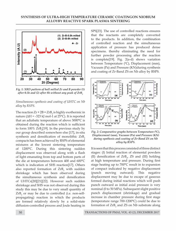
TRANSACTIONS OF PMAI, VOL. 43 (2), DECEMBER 201750
SYNTHESIS OF ULTRA-HIGH TEMPERATURE CERAMIC COATINGON NIOBIUM ALLOYBY REACTIVE SPARK PLASMA SINTERING
Fig. 1: XRD pattern of ball milled Zr and B powder (1) after 0.5h and (2) after 8h without any peak of ZrB2
Fig. 2: Comparative graphs between Temperature (0C), Displacement (mm), Vacuum (Pa) and Pressure (KN) during synthesis and coating of Zr-Band ZS on Nb
alloy by RSPS.
Simultaneous synthesis and coating of UHTC on Nb alloy by RSPS.
The reaction Zr + 2B = ZrB2 is highly exothermic in nature (ΔH = -323 kJ mol-1 at 25°C). It is reported that an adiabatic temperature of above 3000°C is obtained during the reaction which is sufficient to form 100% ZrB2[19]. In the previous study by our group described somewhere else [17], in-situ synthesis and densification of monolithic ZrB2 compacts has been achieved by RSPS of elemental mixtures at the lowest sintering temperature of 1200°C. During this sintering sudden displacement was observed along with a flash of light emanating from top and bottom parts of the die at temperatures between 400 and 600°C which is indication of SHS reaction[17]. Others also reported formation of ZrB2 with sudden shrinkage which has been observed during the simultaneous synthesis and densification of UHTCs[20][21][22]. However such sudden shrinkage and SHS was not observed during this study this may be due to very small quantity of ZrB2 or may be due to controlled (i.e. non-self-propagating) reaction in which the products are formed relatively slowly by a solid-state diffusion-controlled process and Joule heating in
SPS[23]. The use of controlled reactions ensures that the reactants are completely converted to the products. In addition, the combination of controlled reaction and the simultaneous application of pressure has produced dense specimens. thereby eliminating the need for further powder processing after the reaction is complete[19]. Fig. 2(a-d) shows variation between Temperature (0C), Displacement (mm), Vacuum (Pa) and Pressure (KN)during synthesis and coating of Zr-Band ZS on Nb alloy by RSPS.
It is seen that this process consisted of three distinct stages: (I) Initial reaction of elemental powders (II) densification of ZrB2, ZS and (III) holding at high temperature and pressure. During first stage heating up to 700°C result in to expansion of compact indicated by negative displacement (punch moving outward). This negative displacement may be due to escape of gaseous formed during initial reactions which will push punch outward as initial axial pressure is very nominal (0 to 50 MPa). Subsequent slight positive punch displacement (shrinkage) and gradual increase in chamber pressure during first stage (temperature range 700-1200°C) could be due to formation of ZrB2 and ZS on Nb substrate along
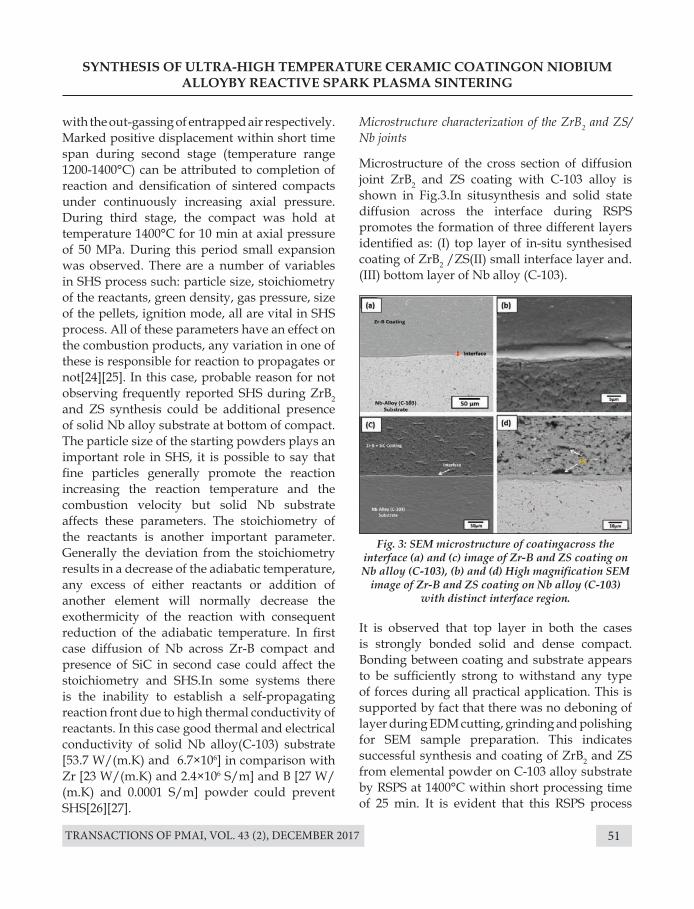
TRANSACTIONS OF PMAI, VOL. 43 (2), DECEMBER 2017 51
SYNTHESIS OF ULTRA-HIGH TEMPERATURE CERAMIC COATINGON NIOBIUM ALLOYBY REACTIVE SPARK PLASMA SINTERING
Fig. 3: SEM microstructure of coatingacross the interface (a) and (c) image of Zr-B and ZS coating on Nb alloy (C-103), (b) and (d) High magnification SEM
image of Zr-B and ZS coating on Nb alloy (C-103) with distinct interface region.
with the out-gassing of entrapped air respectively. Marked positive displacement within short time span during second stage (temperature range 1200-1400°C) can be attributed to completion of reaction and densification of sintered compacts under continuously increasing axial pressure. During third stage, the compact was hold at temperature 1400°C for 10 min at axial pressure of 50 MPa. During this period small expansion was observed. There are a number of variables in SHS process such: particle size, stoichiometry of the reactants, green density, gas pressure, size of the pellets, ignition mode, all are vital in SHS process. All of these parameters have an effect on the combustion products, any variation in one of these is responsible for reaction to propagates or not[24][25]. In this case, probable reason for not observing frequently reported SHS during ZrB2 and ZS synthesis could be additional presence of solid Nb alloy substrate at bottom of compact. The particle size of the starting powders plays an important role in SHS, it is possible to say that fine particles generally promote the reaction increasing the reaction temperature and the combustion velocity but solid Nb substrate affects these parameters. The stoichiometry of the reactants is another important parameter. Generally the deviation from the stoichiometry results in a decrease of the adiabatic temperature, any excess of either reactants or addition of another element will normally decrease the exothermicity of the reaction with consequent reduction of the adiabatic temperature. In first case diffusion of Nb across Zr-B compact and presence of SiC in second case could affect the stoichiometry and SHS.In some systems there is the inability to establish a self-propagating reaction front due to high thermal conductivity of reactants. In this case good thermal and electrical conductivity of solid Nb alloy(C-103) substrate [53.7 W/(m.K) and 6.7×10⁶] in comparison with Zr [23 W/(m.K) and 2.4×10⁶ S/m] and B [27 W/(m.K) and 0.0001 S/m] powder could prevent SHS[26][27].
Microstructure characterization of the ZrB2 and ZS/Nb joints
Microstructure of the cross section of diffusion joint ZrB2 and ZS coating with C-103 alloy is shown in Fig.3.In situsynthesis and solid state diffusion across the interface during RSPS promotes the formation of three different layers identified as: (I) top layer of in-situ synthesised coating of ZrB2 /ZS(II) small interface layer and.(III) bottom layer of Nb alloy (C-103).
It is observed that top layer in both the cases is strongly bonded solid and dense compact. Bonding between coating and substrate appears to be sufficiently strong to withstand any type of forces during all practical application. This is supported by fact that there was no deboning of layer during EDM cutting, grinding and polishing for SEM sample preparation. This indicates successful synthesis and coating of ZrB2 and ZS from elemental powder on C-103 alloy substrate by RSPS at 1400°C within short processing time of 25 min. It is evident that this RSPS process
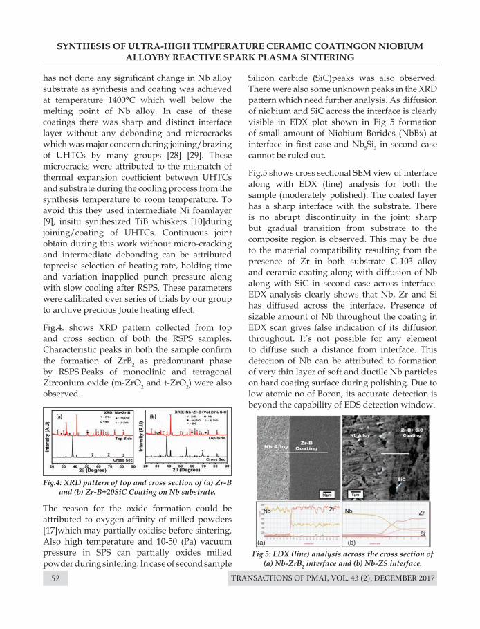
TRANSACTIONS OF PMAI, VOL. 43 (2), DECEMBER 201752
SYNTHESIS OF ULTRA-HIGH TEMPERATURE CERAMIC COATINGON NIOBIUM ALLOYBY REACTIVE SPARK PLASMA SINTERING
has not done any significant change in Nb alloy substrate as synthesis and coating was achieved at temperature 1400°C which well below the melting point of Nb alloy. In case of these coatings there was sharp and distinct interface layer without any debonding and microcracks which was major concern during joining/brazing of UHTCs by many groups [28] [29]. These microcracks were attributed to the mismatch of thermal expansion coefficient between UHTCs and substrate during the cooling process from the synthesis temperature to room temperature. To avoid this they used intermediate Ni foamlayer [9], insitu synthesized TiB whiskers [10]during joining/coating of UHTCs. Continuous joint obtain during this work without micro-cracking and intermediate debonding can be attributed toprecise selection of heating rate, holding time and variation inapplied punch pressure along with slow cooling after RSPS. These parameters were calibrated over series of trials by our group to archive precious Joule heating effect.
Fig.4. shows XRD pattern collected from top and cross section of both the RSPS samples.Characteristic peaks in both the sample confirm the formation of ZrB2 as predominant phase by RSPS.Peaks of monoclinic and tetragonal Zirconium oxide (m-ZrO2 and t-ZrO2) were also observed.
The reason for the oxide formation could be attributed to oxygen affinity of milled powders [17]which may partially oxidise before sintering. Also high temperature and 10-50 (Pa) vacuum pressure in SPS can partially oxides milled powder during sintering. In case of second sample
Fig.4: XRD pattern of top and cross section of (a) Zr-B and (b) Zr-B+20SiC Coating on Nb substrate.
Fig.5: EDX (line) analysis across the cross section of (a) Nb-ZrB2 interface and (b) Nb-ZS interface.
Silicon carbide (SiC)peaks was also observed.There were also some unknown peaks in the XRD pattern which need further analysis. As diffusion of niobium and SiC across the interface is clearly visible in EDX plot shown in Fig 5 formation of small amount of Niobium Borides (NbBx) at interface in first case and Nb5Si3 in second case cannot be ruled out.
Fig.5 shows cross sectional SEM view of interface along with EDX (line) analysis for both the sample (moderately polished). The coated layer has a sharp interface with the substrate. There is no abrupt discontinuity in the joint; sharp but gradual transition from substrate to the composite region is observed. This may be due to the material compatibility resulting from the presence of Zr in both substrate C-103 alloy and ceramic coating along with diffusion of Nb along with SiC in second case across interface.EDX analysis clearly shows that Nb, Zr and Si has diffused across the interface. Presence of sizable amount of Nb throughout the coating in EDX scan gives false indication of its diffusion throughout. It’s not possible for any element to diffuse such a distance from interface. This detection of Nb can be attributed to formation of very thin layer of soft and ductile Nb particles on hard coating surface during polishing. Due to low atomic no of Boron, its accurate detection is beyond the capability of EDS detection window.
(a) (b)
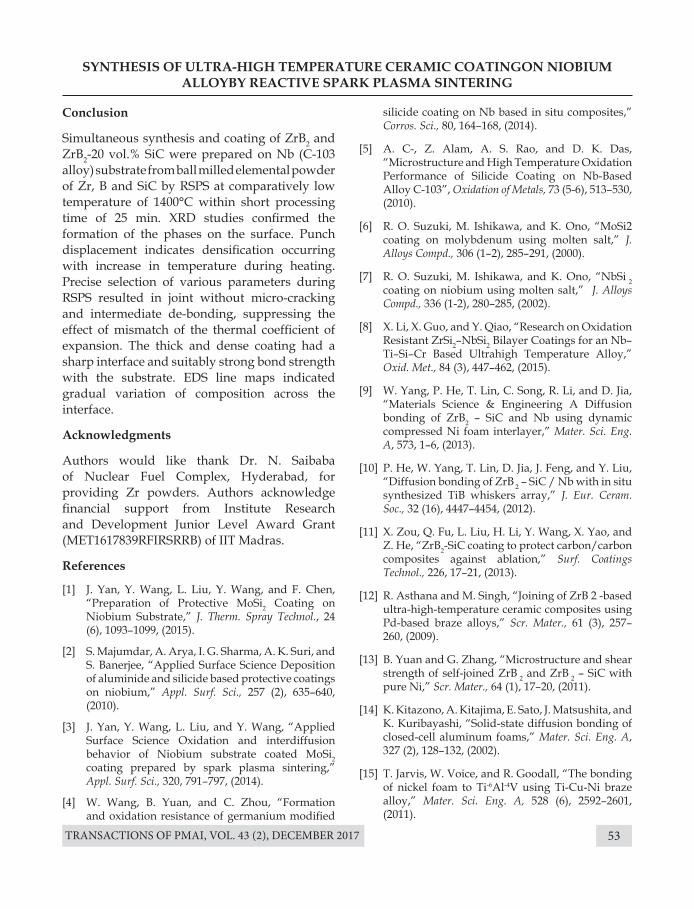
TRANSACTIONS OF PMAI, VOL. 43 (2), DECEMBER 2017 53
SYNTHESIS OF ULTRA-HIGH TEMPERATURE CERAMIC COATINGON NIOBIUM ALLOYBY REACTIVE SPARK PLASMA SINTERING
Conclusion
Simultaneous synthesis and coating of ZrB2 and ZrB2-20 vol.% SiC were prepared on Nb (C-103 alloy) substrate from ball milled elemental powder of Zr, B and SiC by RSPS at comparatively low temperature of 1400°C within short processing time of 25 min. XRD studies confirmed the formation of the phases on the surface. Punch displacement indicates densification occurring with increase in temperature during heating. Precise selection of various parameters during RSPS resulted in joint without micro-cracking and intermediate de-bonding, suppressing the effect of mismatch of the thermal coefficient of expansion. The thick and dense coating had a sharp interface and suitably strong bond strength with the substrate. EDS line maps indicated gradual variation of composition across the interface.
Acknowledgments
Authors would like thank Dr. N. Saibaba of Nuclear Fuel Complex, Hyderabad, for providing Zr powders. Authors acknowledge financial support from Institute Research and Development Junior Level Award Grant (MET1617839RFIRSRRB) of IIT Madras.
References
[1] J. Yan, Y. Wang, L. Liu, Y. Wang, and F. Chen, “Preparation of Protective MoSi2 Coating on Niobium Substrate,” J. Therm. Spray Technol., 24 (6), 1093–1099, (2015).
[2] S. Majumdar, A. Arya, I. G. Sharma, A. K. Suri, and S. Banerjee, “Applied Surface Science Deposition of aluminide and silicide based protective coatings on niobium,” Appl. Surf. Sci., 257 (2), 635–640, (2010).
[3] J. Yan, Y. Wang, L. Liu, and Y. Wang, “Applied Surface Science Oxidation and interdiffusion behavior of Niobium substrate coated MoSi2 coating prepared by spark plasma sintering,” Appl. Surf. Sci., 320, 791–797, (2014).
[4] W. Wang, B. Yuan, and C. Zhou, “Formation and oxidation resistance of germanium modified
silicide coating on Nb based in situ composites,” Corros. Sci., 80, 164–168, (2014).
[5] A. C-, Z. Alam, A. S. Rao, and D. K. Das, “Microstructure and High Temperature Oxidation Performance of Silicide Coating on Nb-Based Alloy C-103”, Oxidation of Metals, 73 (5-6), 513–530, (2010).
[6] R. O. Suzuki, M. Ishikawa, and K. Ono, “MoSi2 coating on molybdenum using molten salt,” J. Alloys Compd., 306 (1–2), 285–291, (2000).
[7] R. O. Suzuki, M. Ishikawa, and K. Ono, “NbSi 2 coating on niobium using molten salt,” J. Alloys Compd., 336 (1-2), 280–285, (2002).
[8] X. Li, X. Guo, and Y. Qiao, “Research on Oxidation Resistant ZrSi2–NbSi2 Bilayer Coatings for an Nb–Ti–Si–Cr Based Ultrahigh Temperature Alloy,” Oxid. Met., 84 (3), 447–462, (2015).
[9] W. Yang, P. He, T. Lin, C. Song, R. Li, and D. Jia, “Materials Science & Engineering A Diffusion bonding of ZrB2 – SiC and Nb using dynamic compressed Ni foam interlayer,” Mater. Sci. Eng. A, 573, 1–6, (2013).
[10] P. He, W. Yang, T. Lin, D. Jia, J. Feng, and Y. Liu, “Diffusion bonding of ZrB 2 – SiC / Nb with in situ synthesized TiB whiskers array,” J. Eur. Ceram. Soc., 32 (16), 4447–4454, (2012).
[11] X. Zou, Q. Fu, L. Liu, H. Li, Y. Wang, X. Yao, and Z. He, “ZrB2-SiC coating to protect carbon/carbon composites against ablation,” Surf. Coatings Technol., 226, 17–21, (2013).
[12] R. Asthana and M. Singh, “Joining of ZrB 2 -based ultra-high-temperature ceramic composites using Pd-based braze alloys,” Scr. Mater., 61 (3), 257–260, (2009).
[13] B. Yuan and G. Zhang, “Microstructure and shear strength of self-joined ZrB 2 and ZrB 2 – SiC with pure Ni,” Scr. Mater., 64 (1), 17–20, (2011).
[14] K. Kitazono, A. Kitajima, E. Sato, J. Matsushita, and K. Kuribayashi, “Solid-state diffusion bonding of closed-cell aluminum foams,” Mater. Sci. Eng. A, 327 (2), 128–132, (2002).
[15] T. Jarvis, W. Voice, and R. Goodall, “The bonding of nickel foam to Ti-6Al-4V using Ti-Cu-Ni braze alloy,” Mater. Sci. Eng. A, 528 (6), 2592–2601, (2011).
TRANSACTIONS OF PMAI, VOL. 43 (2), DECEMBER 201754
SYNTHESIS OF ULTRA-HIGH TEMPERATURE CERAMIC COATINGON NIOBIUM ALLOYBY REACTIVE SPARK PLASMA SINTERING
[16] S. Simões, F. Viana, M. Koak, A. S. Ramos, M. T. Vieira, and M. F. Vieira, “Diffusion bonding of TiAl using reactive Ni/Al nanolayers and Ti and Ni foils,” Mater. Chem. Phys., 128 (1–2), 202–207, (2011).
[17] N. S. Karthiselva, B. S. Murty, and S. R. Bakshi, “Low temperature synthesis of dense and ultrafine grained zirconium diboride compacts by reactive spark plasma sintering,” Scr. Mater., 110, 78–81, (2016).
[18] C. Suryanarayana and N. Al-aqeeli, “Progress in Materials Science Mechanically alloyed nanocomposites,” Prog. Mater. Sci., 58 (4), 383–502, (2013).
[19] A. L. Chamberlain, W. G. Fahrenholtz, and G. E. Hilmas, “Reactive hot pressing of zirconium diboride,” 29, 3401–3408, (2009).
[20] R. Licheri, C. Musa, R. Orrù, and G. Cao, “Influence of the heating rate on the in situ synthesis and consolidation of ZrB2 by reactive Spark Plasma Sintering,” J. Eur. Ceram. Soc., 35 (4), 1129–1137, (2015).
[21] N. S. Karthiselva, B. S. Murty, and S. R. Bakshi, “Low temperature synthesis of dense TiB2 compacts by reaction spark plasma sintering,” Int. J. Refract. Met. Hard Mater., 48, 201–210, (2015).
[22] I. Khobta, O. Petukhov, O. Vasylkiv, Y. Sakka, and A. Ragulya, “Synthesis and consolidation of TiN/TiB2 ceramic composites via reactive spark plasma sintering,” J. Alloys Compd., 509 (5), 1601–1606, (2011).
[23] M. O. H. N. A. G. I. Ya, “The effect of electric field and pressure on the synthesis and consolidation of materials : A review of the spark plasma sintering method,” 1, 763–777, (2006).
[24] H. C. Yi, “Review ( combustion ) synthesis (SHS) of powder-compacted materials: Ti g,” 25, 1159–1168, (1990).
[25] P. Mossino, “Some aspects in self-propagating high-temperature synthesis,” 30, 311–332, (2004).
[26] T. D. Sheet, “C-103 Niobium Properties and Products,” 1–27, (2010).
[27] “Technical data for the element Zirconium in the Periodic Table.”
[28] M. Singh and R. Asthana, “Joining of zirconium diboride-based ultra high-temperature ceramic composites using metallic glass interlayers,” Mater. Sci. & Engg. A, 460-461, 153–162, (2007).
[29] E. W. Neuman, G. E. Hilmas, and W. G. Fahrenholtz, “Mechanical behavior of zirconium diboride-silicon carbide ceramics at elevated temperature in air,” J. Eur. Ceram. Soc., 33 (15–16), 2889–2899, (2013).
TRANSACTIONS OF PMAI, VOL. 43 (2), DECEMBER 2017 55
DEVELOPMENT OF W –Cu FUNCTIONALLY GRADED MATERIAL BY SPARK PLASMA SINTERING
Rajat Gupta1*, Rohit Kumar1, A.K. Chaubey1, Shailesh Kanpara2, S.S. Khirwadkar2 & B. Bhoi1
1CSIR- Institute of Minerals and Materials Technology (IMMT), Bhubaneswar, India.2Institute for Plasma Research, Gandhinagar, India.
Introduction
Plasma facing components (PFCs) for divertor applications play an important role in fusion reactors. They are made of armour material and heat sink material. Tungsten and Copper alloys are the most suitable candidate for plasma facing and heat sink materials respectively in Plasma Facing Components (PFCs). Tungsten has high melting temperature, high sputtering threshold, low tritium retention, good thermal- mechanical properties [1-3]. Besides all above properties, low coefficient of thermal expansion makes it a promising plasma facing material. Additionally, copper is an ideal heat sink material due to high thermal conductivity and high coefficient of thermal expansion [4,5]. However, the large difference in melting point and coefficient of thermal expansion (CTE) of tungsten and copper makes it difficult to fabricate by conventional
Abstract : W-Cu Functionally graded material (FGM) with excellent properties and microstructure is extremely significant in the development of fusion reactors. In present work seven-layered W/Cu FGM (100W, 80W-20Cu, 60W-40Cu, 50W-50Cu, 40W-60Cu, 20W-80Cu, 100Cu (wt %) with each layer having thickness ~1mm) were fabricated by a spark plasma sintering process (SPS). The influences of sintering temperature on relative density, hardness and microstructure at various layers of sintered samples were investigated. The experimental results indicated that the graded structure of the composite could be well densified after the SPS process. The polished layer surface were analysed by optical microscope and scanning electron microscope. Scanning electron microscopy and energy dispersive X-ray spectrometer analysis showed that the graded structure can be retained at a sintering temperature of 10500C and the fine microstructure within each layer can be also maintained due to the short sintering time. The sample sintered at 10500C exhibited excellent mechanical and physical properties with higher hardness 239±5 Hv and maximum densification has been achieved 94.45% of their theoretical density.
Keywords: Functionally graded material, Mechanical properties; Spark Plasma Sintering; Plasma Facing Components
methods like brazing, conventional sintering will result in thermally induced stresses at the interface.
FGM is an inhomogeneous material with a gradually changing composition of two metals with different properties. It can minimise thermal stresses caused by difference of the CTE between W and Cu, and thus have gained considerable importance in extremely high temperature environments. In FGM the property changes gradually with position. The property gradient in the material is caused by a position dependent chemical composition, microstructure or atomic order. In this study composition gradient is maintained as a function of position. FGM can optimize both material and component structures to mitigate the problem of thermal stress distributions and fracture of material to achieve high performance and
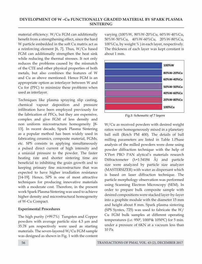
TRANSACTIONS OF PMAI, VOL. 43 (2), DECEMBER 201756
DEVELOPMENT OF W –Cu FUNCTIONALLY GRADED MATERIAL BY SPARK PLASMA SINTERING
material efficiency. W/Cu FGM can additionally benefit from a strengthening effect, since the hard W particle embedded in the soft Cu matrix act as a reinforcing element [6, 7]. Thus, W/Cu based FGM can additionally strengthen the heat sink while reducing the thermal stresses. It not only reduces the problems caused by the mismatch of the CTE and other physical properties of both metals, but also combines the features of W and Cu as above mentioned. Hence FGM is an appropriate option as interlayer between W and Cu for (PFC) to minimize these problems when used as interlayer.
Techniques like plasma spraying slip casting, chemical vapour deposition and pressure infiltration have been employed previously for the fabrication of PFCs, but they are expensive, complex and give FGM of less density and non uniform microstructure homogeneity [8-13]. In recent decade, Spark Plasma Sintering as a popular method has been widely used in fabricating ceramics, composite material, FGMs, etc. SPS consists in applying simultaneously a pulsed direct current of high intensity and a uniaxial pressure to the powder. The faster heating rate and shorter sintering time are beneficial to inhibiting the grain growth and to keeping primary fine microstructure that was expected to have higher irradiation resistance [14-19]. Hence, SPS is one of most attractive techniques for producing innovative materials with a moderate cost. Therefore, in the present work Spark Plasma Sintering was used to achieve higher density and microstructural homogeneity of W-Cu Compact.
Experimental Procedures
The high purity (>99.7%) Tungsten and Copper powders with average particle size 4.3 µm and 35.78 µm respectively were used as starting materials. The seven-layered W/Cu FGM sample was designed as shown in Fig. 1 with the content
varying (100%W, 80%W-20%Cu, 60%W-40%Cu, 50%W-50%Cu, 40%W-60%Cu, 20%W-80%Cu, 100%Cu, by weight % ) in each layer, respectively. The thickness of each layer was kept constant is about 1 mm.
Fig.1: Schematic of 7 layers
W/Cu as received powders with desired weight ratios were homogeneously mixed in a planetary ball mill (Retch PM 400). The details of ball milling parameters are listed in Table 1.Phase analysis of the milled powders were done using powder diffraction technique with the help of X’Pert PRO PAN alytical’s materials research Diffractometer (λ=1.54184 Å) and particle size were analyzed by particle size analyzer (MASTERSIZER) with water as dispersant which is based on laser diffraction technique. The particle morphology observation was performed using Scanning Electron Microscopy (SEM). In order to prepare bulk composite sample with desired compositions were stacked layer-by-layer into a graphite module with the diameter 15 mm and height about 8 mm. Spark plasma sintering (SPS Syntex, 725) was used to fabricate the W/Cu FGM bulk samples at different operating temperatures (i.e. 9500, 10000& 10500C) for 5 min. under a pressure of 6KN at a vacuum less than 10 Pa.
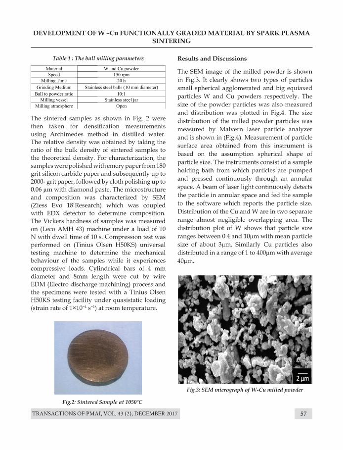
TRANSACTIONS OF PMAI, VOL. 43 (2), DECEMBER 2017 57
DEVELOPMENT OF W –Cu FUNCTIONALLY GRADED MATERIAL BY SPARK PLASMA SINTERING
Results and Discussions
The SEM image of the milled powder is shown in Fig.3. It clearly shows two types of particles small spherical agglomerated and big equiaxed particles W and Cu powders respectively. The size of the powder particles was also measured and distribution was plotted in Fig.4. The size distribution of the milled powder particles was measured by Malvern laser particle analyzer and is shown in (Fig.4). Measurement of particle surface area obtained from this instrument is based on the assumption spherical shape of particle size. The instruments consist of a sample holding bath from which particles are pumped and pressed continuously through an annular space. A beam of laser light continuously detects the particle in annular space and fed the sample to the software which reports the particle size. Distribution of the Cu and W are in two separate range almost negligible overlapping area. The distribution plot of W shows that particle size ranges between 0.4 and 10µm with mean particle size of about 3µm. Similarly Cu particles also distributed in a range of 1 to 400µm with average 40µm.
The sintered samples as shown in Fig. 2 were then taken for densification measurements using Archimedes method in distilled water. The relative density was obtained by taking the ratio of the bulk density of sintered samples to the theoretical density. For characterization, the samples were polished with emery paper from 180 grit silicon carbide paper and subsequently up to 2000- grit paper, followed by cloth polishing up to 0.06 µm with diamond paste. The microstructure and composition was characterized by SEM (Ziess Evo 18’Research) which was coupled with EDX detector to determine composition. The Vickers hardness of samples was measured on (Leco AMH 43) machine under a load of 10 N with dwell time of 10 s. Compression test was performed on (Tinius Olsen H50KS) universal testing machine to determine the mechanical behaviour of the samples while it experiences compressive loads. Cylindrical bars of 4 mm diameter and 8mm length were cut by wire EDM (Electro discharge machining) process and the specimens were tested with a Tinius Olsen H50KS testing facility under quasistatic loading (strain rate of 1×10⁻⁴ s−1) at room temperature.
Fig.2: Sintered Sample at 1050ºC
Fig.3: SEM micrograph of W-Cu milled powder
Table 1 : The ball milling parameters
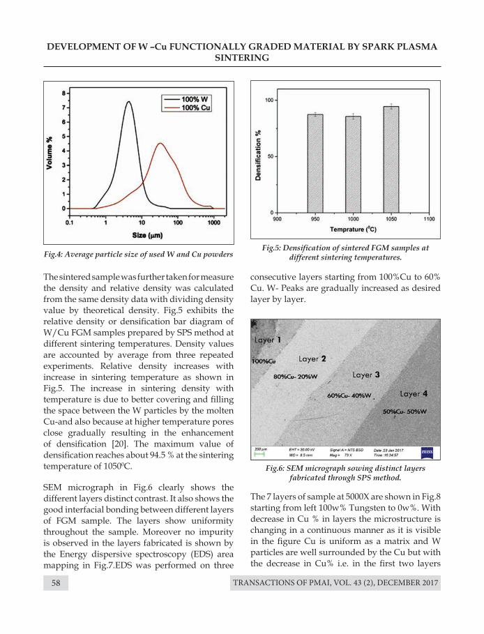
TRANSACTIONS OF PMAI, VOL. 43 (2), DECEMBER 201758
Fig.4: Average particle size of used W and Cu powdersFig.5: Densification of sintered FGM samples at
different sintering temperatures.
Fig.6: SEM micrograph sowing distinct layers fabricated through SPS method.
DEVELOPMENT OF W –Cu FUNCTIONALLY GRADED MATERIAL BY SPARK PLASMA SINTERING
The sintered sample was further taken for measure the density and relative density was calculated from the same density data with dividing density value by theoretical density. Fig.5 exhibits the relative density or densification bar diagram of W/Cu FGM samples prepared by SPS method at different sintering temperatures. Density values are accounted by average from three repeated experiments. Relative density increases with increase in sintering temperature as shown in Fig.5. The increase in sintering density with temperature is due to better covering and filling the space between the W particles by the molten Cu-and also because at higher temperature pores close gradually resulting in the enhancement of densification [20]. The maximum value of densification reaches about 94.5 % at the sintering temperature of 10500C.
SEM micrograph in Fig.6 clearly shows the different layers distinct contrast. It also shows the good interfacial bonding between different layers of FGM sample. The layers show uniformity throughout the sample. Moreover no impurity is observed in the layers fabricated is shown by the Energy dispersive spectroscopy (EDS) area mapping in Fig.7.EDS was performed on three
consecutive layers starting from 100%Cu to 60% Cu. W- Peaks are gradually increased as desired layer by layer.
The 7 layers of sample at 5000X are shown in Fig.8 starting from left 100w% Tungsten to 0w%. With decrease in Cu % in layers the microstructure is changing in a continuous manner as it is visible in the figure Cu is uniform as a matrix and W particles are well surrounded by the Cu but with the decrease in Cu% i.e. in the first two layers
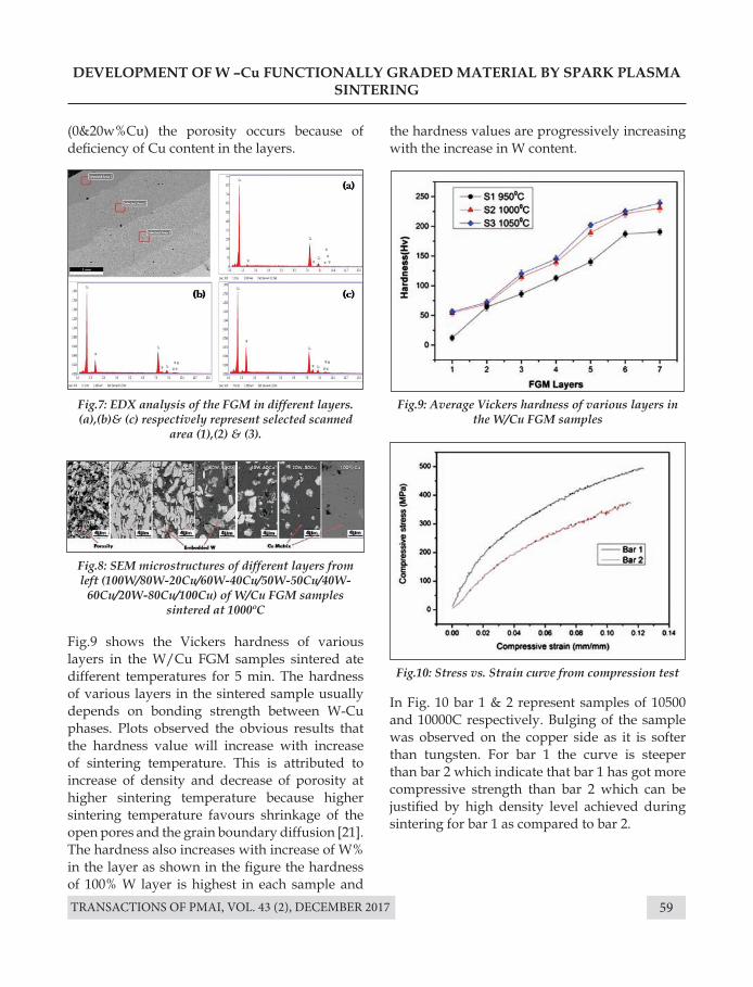
TRANSACTIONS OF PMAI, VOL. 43 (2), DECEMBER 2017 59
Fig.7: EDX analysis of the FGM in different layers. (a),(b)& (c) respectively represent selected scanned
area (1),(2) & (3).
Fig.9: Average Vickers hardness of various layers in the W/Cu FGM samples
Fig.10: Stress vs. Strain curve from compression test
Fig.8: SEM microstructures of different layers from left (100W/80W-20Cu/60W-40Cu/50W-50Cu/40W-
60Cu/20W-80Cu/100Cu) of W/Cu FGM samples sintered at 1000ºC
DEVELOPMENT OF W –Cu FUNCTIONALLY GRADED MATERIAL BY SPARK PLASMA SINTERING
(0&20w%Cu) the porosity occurs because of deficiency of Cu content in the layers.
Fig.9 shows the Vickers hardness of various layers in the W/Cu FGM samples sintered ate different temperatures for 5 min. The hardness of various layers in the sintered sample usually depends on bonding strength between W-Cu phases. Plots observed the obvious results that the hardness value will increase with increase of sintering temperature. This is attributed to increase of density and decrease of porosity at higher sintering temperature because higher sintering temperature favours shrinkage of the open pores and the grain boundary diffusion [21]. The hardness also increases with increase of W% in the layer as shown in the figure the hardness of 100% W layer is highest in each sample and
the hardness values are progressively increasing with the increase in W content.
In Fig. 10 bar 1 & 2 represent samples of 10500 and 10000C respectively. Bulging of the sample was observed on the copper side as it is softer than tungsten. For bar 1 the curve is steeper than bar 2 which indicate that bar 1 has got more compressive strength than bar 2 which can be justified by high density level achieved during sintering for bar 1 as compared to bar 2.
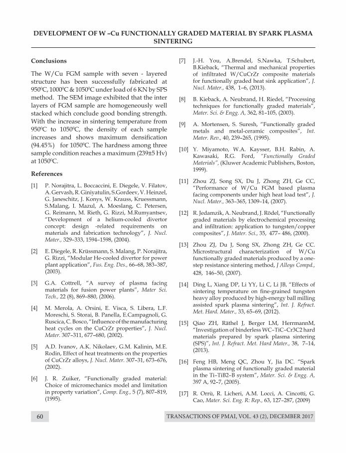
TRANSACTIONS OF PMAI, VOL. 43 (2), DECEMBER 201760
DEVELOPMENT OF W –Cu FUNCTIONALLY GRADED MATERIAL BY SPARK PLASMA SINTERING
Conclusions
The W/Cu FGM sample with seven - layered structure has been successfully fabricated at 9500C, 10000C & 10500C under load of 6 KN by SPS method. The SEM image exhibited that the inter layers of FGM sample are homogeneously well stacked which conclude good bonding strength. With the increase in sintering temperature from 9500C to 10500C, the density of each sample increases and shows maximum densification (94.45%) for 10500C. The hardness among three sample condition reaches a maximum (239±5 Hv) at 10500C.
References
[1] P. Norajitra, L. Boccaccini, E. Diegele, V. Filatov, A. Gervash, R. Giniyatulin, S.Gordeev, V. Heinzel, G. Janeschitz, J. Konys, W. Krauss, Kruessmann, S.Malang, I. Mazul, A. Moeslang, C. Petersen, G. Reimann, M. Rieth, G. Rizzi, M.Rumyantsev, “Development of a helium-cooled divertor concept: design -related requirements on materials and fabrication technology”, J. Nucl. Mater., 329–333, 1594–1598, (2004).
[2] E. Diegele, R. Krüssmann, S. Malang, P. Norajitra, G. Rizzi, “Modular He-cooled divertor for power plant application”, Fus. Eng. Des., 66–68, 383–387, (2003).
[3] G.A. Cottrell, “A survey of plasma facing materials for fusion power plants”, Mater Sci. Tech., 22 (8), 869–880, (2006).
[4] M. Merola, A. Orsini, E. Visca, S. Libera, L.F. Moreschi, S. Storai, B. Panella, E.Campagnoli, G. Ruscica, C. Bosco, “Influence of the manufacturing heat cycles on the CuCrZr properties”, J. Nucl. Mater. 307–311, 677–680, (2002).
[5] A.D. Ivanov, A.K. Nikolaev, G.M. Kalinin, M.E. Rodin, Effect of heat treatments on the properties of CuCrZr alloys, J. Nucl. Mater. 307–31, 673–676, (2002).
[6] J. R. Zuiker, “Functionally graded material: Choice of micromechanics model and limitation in property variation”, Comp. Eng., 5 (7), 807–819, (1995).
[7] J.-H. You, A.Brendel, S.Nawka, T.Schubert, B.Kieback, “Thermal and mechanical properties of infiltrated W/CuCrZr composite materials for functionally graded heat sink application”, J. Nucl. Mater., 438, 1–6, (2013).
[8] B. Kieback, A. Neubrand, H. Riedel, “Processing techniques for functionally graded materials”, Mater. Sci. & Engg. A, 362, 81–105, (2003).
[9] A. Mortensen, S. Suresh, “Functionally graded metals and metal-ceramic composites”, Int. Mater. Rev., 40, 239–265, (1995).
[10] Y. Miyamoto, W.A. Kaysser, B.H. Rabin, A. Kawasaki, R.G. Ford, “Functionally Graded Materials”, (Kluwer Academic Publishers, Boston, 1999).
[11] Zhou ZJ, Song SX, Du J, Zhong ZH, Ge CC, “Performance of W/Cu FGM based plasma facing components under high heat load test”, J. Nucl. Mater., 363–365, 1309–14, (2007).
[12] R. Jedamzik, A. Neubrand, J. Rödel, “Functionally graded materials by electrochemical processing and infiltration: application to tungsten/copper composites”, J. Mater. Sci., 35, 477– 486, (2000).
[13] Zhou ZJ, Du J, Song SX, Zhong ZH, Ge CC. Microstructural characterization of W/Cu functionally graded materials produced by a one-step resistance sintering method, J Alloys Compd., 428, 146–50, (2007).
[14] Ding L, Xiang DP, Li YY, Li C, Li JB, “Effects of sintering temperature on fine-grained tungsten heavy alloy produced by high-energy ball milling assisted spark plasma sintering”, Int. J. Refract. Met. Hard. Mater., 33, 65–69, (2012).
[15] Qiao ZH, Räthel J, Berger LM, HerrmannM, “Investigation of binderless WC–TiC–Cr3C2 hard materials prepared by spark plasma sintering (SPS)”, Int. J. Refract. Met. Hard Mater., 38, 7–14, (2013).
[16] Feng HB, Meng QC, Zhou Y, Jia DC. “Spark plasma sintering of functionally graded material in the Ti–TiB2–B system”, Mater. Sci. & Engg. A, 397 A, 92–7, (2005).
[17] R. Orrù, R. Licheri, A.M. Locci, A. Cincotti, G. Cao, Mater. Sci. Eng. R: Rep., 63, 127–287, (2009)
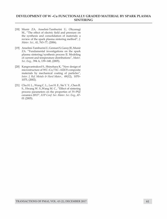
TRANSACTIONS OF PMAI, VOL. 43 (2), DECEMBER 2017 61
DEVELOPMENT OF W –Cu FUNCTIONALLY GRADED MATERIAL BY SPARK PLASMA SINTERING
[18] Munir ZA, Anselmi-Tamburini U, Ohyanagi M., “The effect of electric field and pressure on the synthesis and consolidation of materials: a review of the spark plasma sintering method”, J. Mater. Sci., 41, 763–77, (2006).
[19] Anselmi-Tamburini U, Gennari S, Garay JE, Munir ZA. “Fundamental investigations on the spark plasma sintering/synthesis process II. Modeling of current and temperature distributions”, Mater. Sci. Eng., 394 A, 139–148, (2005).
[20] Kangwantrakool S., Shinohara K, “New design of microstructure of WC–Co/TiC–Al2O3 composite materials by mechanical coating of particles”, Inter. J. Ref. Metals & Hard Mater., 49(12), 1070–1075, (2002).
[21] Chu H. L., Wang C. L., Lee H. E., Sie Y. Y., Chen R. S., Hwang W. S.,Wang M. C., “Effect of sintering process parameters on the properties of 3Y-PSZ ceramics 2013”, IOP Conf. Ser. Mater. Sci. Eng., 47-01 (2005).
TRANSACTIONS OF PMAI, VOL. 43 (2), DECEMBER 201762
FINITE ELEMENT BASED COMPARISON OF VARIOUS MATERIALS FOR CHARGE CARRIER BOATS USED IN
SINTERING OPERATION OF NUCLEAR FUEL FABRICATION
Sumit Raghuvanshi, U.K. Arora, A.C. Wali, G. Kalyanakrishnan
Nuclear Fuel Complex, Department of Atomic Energy, Hyderabad, India.
Introduction
Nuclear Fuel Complex (NFC), an industrial unit of Department of Atomic Energy, India, has been manufacturing, over the past three decades, natural and enriched uranium oxide fuels for all the nuclear power reactors in India. The pellets are manufactured from nuclear grade UO2 powder produced through ammonium di-uranate (ADU) precipitate route. Powder metallurgy route has been established, to convert UO2 powder into sintered UO2 pellets. These UO2 pellets are used as nuclear fuel for all types of nuclear reactors[1]. The powder metallurgy process of UO2 pellet fabrication involves pre-compaction, final compaction, sintering and grinding operations. Granulated powder is compacted in compaction press by applying required biaxial compaction pressure. Compacted pellets are called as green pellets because of low strength and less density.
Abstract : Powder metallurgy route is followed for Uranium oxide (UO2) pellet fabrication. Green UO2 pellets are arranged systematically in presently used Molybdenum containers, termed as charge carrier boats. These carrier boats are charged into continuous sintering furnace for pellet densification operating at 1700oC. Carrier boats have to face high thermo-mechanical loads due to high temperature and green UO2 pellets under reducing atmosphere. These thermos-mechanical loads generates permanent deformation/distortion in carrier boats. Creep deformation and plasticity in material leads to severe distortion of boats and Permanent deformations in boats are accumulated due to multiple cycles of operation over the period. Excessive distortion in carrier boat restricts its further usage. Therefore, the aim of this study is to reduce amount of excessive distortions i.e. Probable increase in the operational life of charge carriers. Design modifications are performed by focusing on Material of fabrication. Various materials for carrier boats has been compared to identify most suitable material. Finite element analysis was performed, to obtain permanent strain in carrier boats due to thermo-mechanical loads. Based on the analysis candidate materials were compared to identify best-suited material considering lowest permanent strain.
Keywords: Uranium Oxide, Pellets, Charge Carrier boats, Strain, Molybdenum
Green UO2 pellets are arranged systematically in presently used Molybdenum containers, termed as carrier boats [2]. Carrier boats are placed on Molybdenum base plates to make them as charge carrier. These green UO2 pellets are charged into continuous sintering furnace for densification operating at 1700oC.
The charge carrier boat has to pass through thermal cyclic loading along with pellet load in the sintering furnace for multiple cycles. This thermo-mechanical loading generates permanent deformations in charge carriers and make them unusable after certain number of operation cycles[3]. The aim of this work is to compare various materials, which is most suitable for charge carrier boats. Existing charge carrier boats have material of construction as pure Molybdenum, because it has minimum coefficient of thermal expansion among other
TRANSACTIONS OF PMAI, VOL. 43 (2), DECEMBER 2017 63
FINITE ELEMENT BASED COMPARISON OF VARIOUS MATERIALS FOR CHARGE CARRIER BOATS USED IN SINTERING OPERATION OF NUCLEAR FUEL
FABRICATION
high temperature materials. This prevents excessive expansion in boats during sintering operation, thereby reducing stresses generated as well as permanent strains in charge carriers. However, pure Molybdenum has some other disadvantages like ductile to brittle transition after heating cycle, low fatigue strength etc.
There are other materials, which has better creep-fatigue resistance than pure moly, and these materials can be used for sintering charge carrier boats. Mainly refractory metals are used for such high temperature applications [4].
Methodology of Solution
The comparison between various materials for boats involves identification of desired material properties for Uranium di-oxide pellet sintering, selection of candidate materials from literature based on desired characteristics, Non-linear finite element analysis of selected candidate materials and comparison based on elsato-plastic creep permanent strain & economy. Material comparison has been performed by modelling complex behavior of various materials and furnace heating/cooling cycles in finite element package. Material properties are collected/extrapolated from literature to get results close to actual values. Materials are modelled by considering variation in properties with respect to temperature & time. Coefficient of thermal expansion and modulus of elasticity, plasticity are derived with respect to temperature variation up to 2000oC. Combine modelling of creep and plasticity replicate actual material behavior during sintering in finite element package.
Charge carrier model has been simulated in FE codes with various materials model along with associated loading and boundary conditions to get permanent strains, deformations and stresses. Materials are compared for plastic deformations, strains, stresses and their resistance to creep deformation/distortion. Materials are also
compared based on economy point of view, as economy is one of the major challenge in nuclear fuel fabrication. Permanent strain in carrier boats are considered as the key feature to indicate superiority of material. Candidate materials are compared based on total accumulated permanent strains and economical aspects. The selected candidate materials are pure Molybdenum, TZM alloy (0.50 Ti, 0.08 Zr, Moly), ML alloy (Molybdenum Lanthanum oxide) and Pure Tungsten [4].
Theoretical Analysis
The carrier boats were analyzed theoretically by using finite element method. In finite element code, charge carrier boat is modelled with combination of various material models and carrier boat geometry. The material model consists of isotropic elasto-plastic & creep modelling of various refractory materials. Both creep and plasticity has been considered to get interactive behavior of materials at elevated temperatures [5].
Finite element analysis is performed to obtain total accumulated strain in charge carrier boats during sintering operation. Total accumulated strain is sum of elastic & plastic strain, thermal strain and creep strain. It takes large number of cycles of operation to deform carrier boats. Therefore, to simulate repeated thermal cyclic behavior, it was assumed that the accumulation of total strain in each cycle is same Therefore, analysis has been performed for one cycle of sintering operation and materials are compared
Pre-processing and Post-processing of finite element analysis are briefly discussed.
A. Pre-processingThe charge carrier boat is a thin sheet structure, so transverse shear along the thickness of sheet can be consider as negligible. Therefore, boat geometry is modelled with shell elements. The
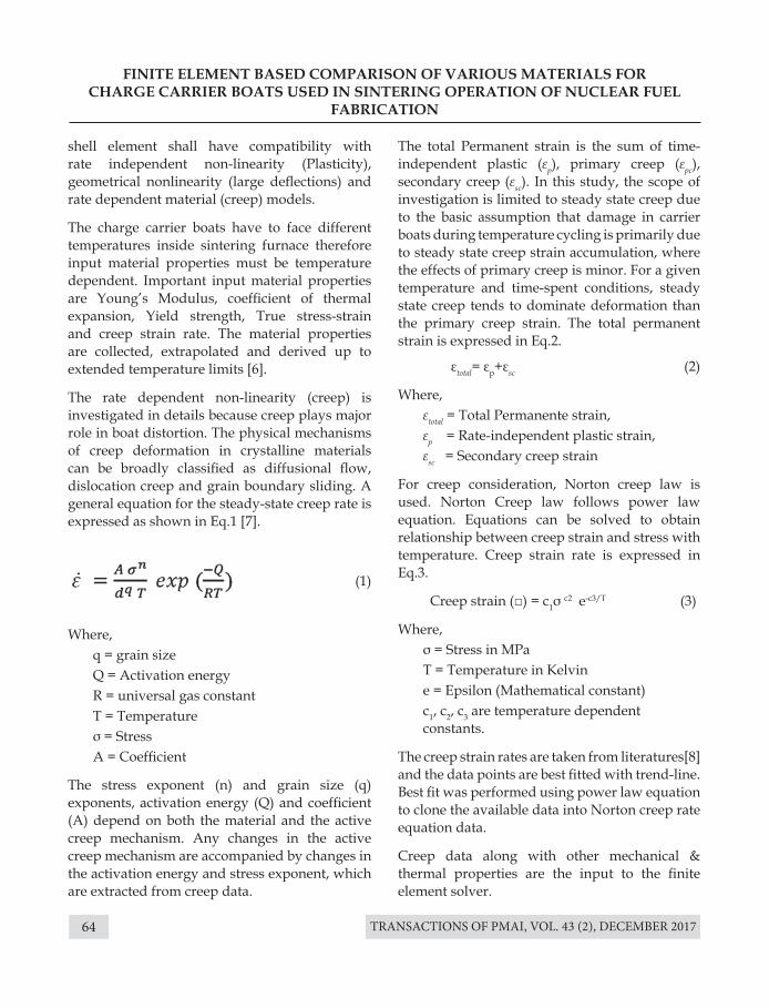
TRANSACTIONS OF PMAI, VOL. 43 (2), DECEMBER 201764
FINITE ELEMENT BASED COMPARISON OF VARIOUS MATERIALS FOR CHARGE CARRIER BOATS USED IN SINTERING OPERATION OF NUCLEAR FUEL
FABRICATION
shell element shall have compatibility with rate independent non-linearity (Plasticity), geometrical nonlinearity (large deflections) and rate dependent material (creep) models.
The charge carrier boats have to face different temperatures inside sintering furnace therefore input material properties must be temperature dependent. Important input material properties are Young’s Modulus, coefficient of thermal expansion, Yield strength, True stress-strain and creep strain rate. The material properties are collected, extrapolated and derived up to extended temperature limits [6].
The rate dependent non-linearity (creep) is investigated in details because creep plays major role in boat distortion. The physical mechanisms of creep deformation in crystalline materials can be broadly classified as diffusional flow, dislocation creep and grain boundary sliding. A general equation for the steady-state creep rate is expressed as shown in Eq.1 [7].
Where, q = grain size Q = Activation energy R = universal gas constant T = Temperature σ = Stress A = Coefficient
The stress exponent (n) and grain size (q) exponents, activation energy (Q) and coefficient (A) depend on both the material and the active creep mechanism. Any changes in the active creep mechanism are accompanied by changes in the activation energy and stress exponent, which are extracted from creep data.
The total Permanent strain is the sum of time-independent plastic (εp), primary creep (εpc), secondary creep (εsc). In this study, the scope of investigation is limited to steady state creep due to the basic assumption that damage in carrier boats during temperature cycling is primarily due to steady state creep strain accumulation, where the effects of primary creep is minor. For a given temperature and time-spent conditions, steady state creep tends to dominate deformation than the primary creep strain. The total permanent strain is expressed in Eq.2.
εtotal= εp+εsc (2)
Where, εtotal = Total Permanente strain, εp = Rate-independent plastic strain, εsc = Secondary creep strain
For creep consideration, Norton creep law is used. Norton Creep law follows power law equation. Equations can be solved to obtain relationship between creep strain and stress with temperature. Creep strain rate is expressed in Eq.3.
Creep strain (□) = c1σ c2 e-c3/T (3)
Where, σ = Stress in MPa T = Temperature in Kelvin e = Epsilon (Mathematical constant) c1, c2, c3 are temperature dependent constants.
The creep strain rates are taken from literatures[8] and the data points are best fitted with trend-line. Best fit was performed using power law equation to clone the available data into Norton creep rate equation data.
Creep data along with other mechanical & thermal properties are the input to the finite element solver.
(1)
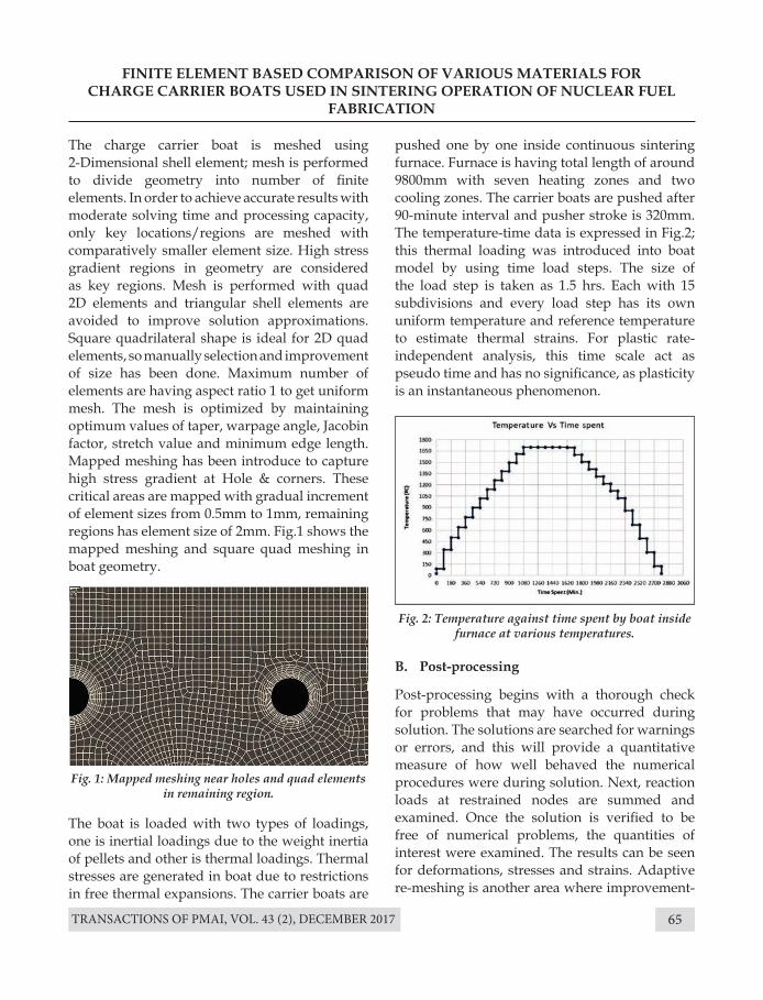
TRANSACTIONS OF PMAI, VOL. 43 (2), DECEMBER 2017 65
FINITE ELEMENT BASED COMPARISON OF VARIOUS MATERIALS FOR CHARGE CARRIER BOATS USED IN SINTERING OPERATION OF NUCLEAR FUEL
FABRICATION
The boat is loaded with two types of loadings, one is inertial loadings due to the weight inertia of pellets and other is thermal loadings. Thermal stresses are generated in boat due to restrictions in free thermal expansions. The carrier boats are
The charge carrier boat is meshed using 2-Dimensional shell element; mesh is performed to divide geometry into number of finite elements. In order to achieve accurate results with moderate solving time and processing capacity, only key locations/regions are meshed with comparatively smaller element size. High stress gradient regions in geometry are considered as key regions. Mesh is performed with quad 2D elements and triangular shell elements are avoided to improve solution approximations. Square quadrilateral shape is ideal for 2D quad elements, so manually selection and improvement of size has been done. Maximum number of elements are having aspect ratio 1 to get uniform mesh. The mesh is optimized by maintaining optimum values of taper, warpage angle, Jacobin factor, stretch value and minimum edge length. Mapped meshing has been introduce to capture high stress gradient at Hole & corners. These critical areas are mapped with gradual increment of element sizes from 0.5mm to 1mm, remaining regions has element size of 2mm. Fig.1 shows the mapped meshing and square quad meshing in boat geometry.
Fig. 1: Mapped meshing near holes and quad elements in remaining region.
Fig. 2: Temperature against time spent by boat inside furnace at various temperatures.
pushed one by one inside continuous sintering furnace. Furnace is having total length of around 9800mm with seven heating zones and two cooling zones. The carrier boats are pushed after 90-minute interval and pusher stroke is 320mm. The temperature-time data is expressed in Fig.2; this thermal loading was introduced into boat model by using time load steps. The size of the load step is taken as 1.5 hrs. Each with 15 subdivisions and every load step has its own uniform temperature and reference temperature to estimate thermal strains. For plastic rate-independent analysis, this time scale act as pseudo time and has no significance, as plasticity is an instantaneous phenomenon.
B. Post-processing
Post-processing begins with a thorough check for problems that may have occurred during solution. The solutions are searched for warnings or errors, and this will provide a quantitative measure of how well behaved the numerical procedures were during solution. Next, reaction loads at restrained nodes are summed and examined. Once the solution is verified to be free of numerical problems, the quantities of interest were examined. The results can be seen for deformations, stresses and strains. Adaptive re-meshing is another area where improvement-
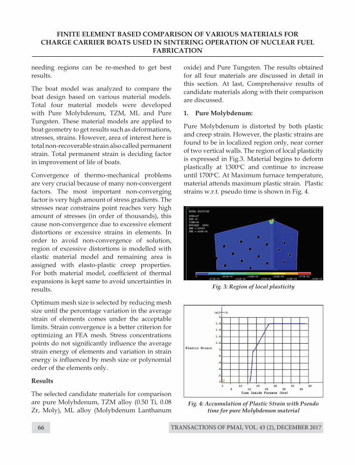
TRANSACTIONS OF PMAI, VOL. 43 (2), DECEMBER 201766
needing regions can be re-meshed to get best results.
The boat model was analyzed to compare the boat design based on various material models. Total four material models were developed with Pure Molybdenum, TZM, ML and Pure Tungsten. These material models are applied to boat geometry to get results such as deformations, stresses, strains. However, area of interest here is total non-recoverable strain also called permanent strain. Total permanent strain is deciding factor in improvement of life of boats.
Convergence of thermo-mechanical problems are very crucial because of many non-convergent factors. The most important non-converging factor is very high amount of stress gradients. The stresses near constrains point reaches very high amount of stresses (in order of thousands), this cause non-convergence due to excessive element distortions or excessive strains in elements. In order to avoid non-convergence of solution, region of excessive distortions is modelled with elastic material model and remaining area is assigned with elasto-plastic creep properties. For both material model, coefficient of thermal expansions is kept same to avoid uncertainties in results.
Optimum mesh size is selected by reducing mesh size until the percentage variation in the average strain of elements comes under the acceptable limits. Strain convergence is a better criterion for optimizing an FEA mesh. Stress concentrations points do not significantly influence the average strain energy of elements and variation in strain energy is influenced by mesh size or polynomial order of the elements only.
Results
The selected candidate materials for comparison are pure Molybdenum, TZM alloy (0.50 Ti, 0.08 Zr, Moly), ML alloy (Molybdenum Lanthanum
FINITE ELEMENT BASED COMPARISON OF VARIOUS MATERIALS FOR CHARGE CARRIER BOATS USED IN SINTERING OPERATION OF NUCLEAR FUEL
FABRICATION
oxide) and Pure Tungsten. The results obtained for all four materials are discussed in detail in this section. At last, Comprehensive results of candidate materials along with their comparison are discussed.
1. Pure Molybdenum:
Pure Molybdenum is distorted by both plastic and creep strain. However, the plastic strains are found to be in localized region only, near corner of two vertical walls. The region of local plasticity is expressed in Fig.3. Material begins to deform plastically at 1300oC and continue to increase until 1700oC. At Maximum furnace temperature, material attends maximum plastic strain. Plastic strains w.r.t. pseudo time is shown in Fig. 4.
Fig. 3: Region of local plasticity
Fig. 4: Accumulation of Plastic Strain with Pseudo time for pure Molybdenum material
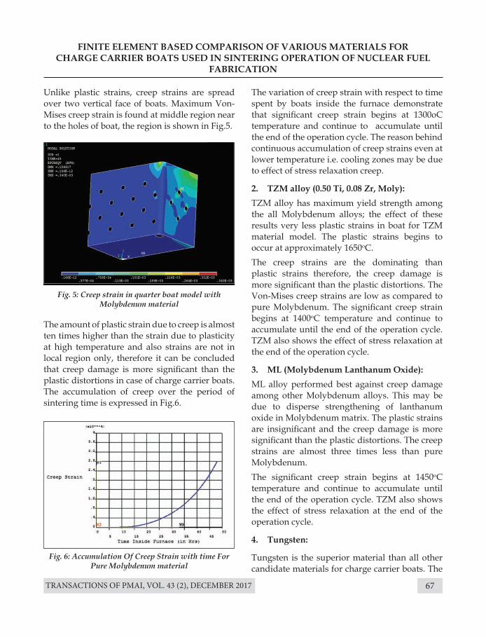
TRANSACTIONS OF PMAI, VOL. 43 (2), DECEMBER 2017 67
FINITE ELEMENT BASED COMPARISON OF VARIOUS MATERIALS FOR CHARGE CARRIER BOATS USED IN SINTERING OPERATION OF NUCLEAR FUEL
FABRICATION
Unlike plastic strains, creep strains are spread over two vertical face of boats. Maximum Von-Mises creep strain is found at middle region near to the holes of boat, the region is shown in Fig.5.
The amount of plastic strain due to creep is almost ten times higher than the strain due to plasticity at high temperature and also strains are not in local region only, therefore it can be concluded that creep damage is more significant than the plastic distortions in case of charge carrier boats. The accumulation of creep over the period of sintering time is expressed in Fig.6.
The variation of creep strain with respect to time spent by boats inside the furnace demonstrate that significant creep strain begins at 1300oC temperature and continue to accumulate until the end of the operation cycle. The reason behind continuous accumulation of creep strains even at lower temperature i.e. cooling zones may be due to effect of stress relaxation creep.
2. TZM alloy (0.50 Ti, 0.08 Zr, Moly): TZM alloy has maximum yield strength among the all Molybdenum alloys; the effect of these results very less plastic strains in boat for TZM material model. The plastic strains begins to occur at approximately 1650oC. The creep strains are the dominating than plastic strains therefore, the creep damage is more significant than the plastic distortions. The Von-Mises creep strains are low as compared to pure Molybdenum. The significant creep strain begins at 1400oC temperature and continue to accumulate until the end of the operation cycle. TZM also shows the effect of stress relaxation at the end of the operation cycle.
3. ML (Molybdenum Lanthanum Oxide):ML alloy performed best against creep damage among other Molybdenum alloys. This may be due to disperse strengthening of lanthanum oxide in Molybdenum matrix. The plastic strains are insignificant and the creep damage is more significant than the plastic distortions. The creep strains are almost three times less than pure Molybdenum. The significant creep strain begins at 1450oC temperature and continue to accumulate until the end of the operation cycle. TZM also shows the effect of stress relaxation at the end of the operation cycle.
4. Tungsten:
Tungsten is the superior material than all other candidate materials for charge carrier boats. The
Fig. 5: Creep strain in quarter boat model with Molybdenum material
Fig. 6: Accumulation Of Creep Strain with time For Pure Molybdenum material
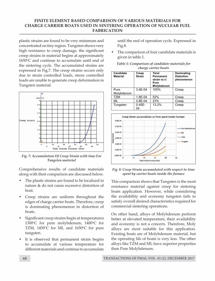
TRANSACTIONS OF PMAI, VOL. 43 (2), DECEMBER 201768
plastic strains are found to be very minimum and concentrated on tiny region. Tungsten shows very high resistance to creep damage, the significant creep strains in material begins at approximately 1650oC and continue to accumulate until end of the sintering cycle. The accumulated strains are expressed in Fig.7. The creep strains occurs only due to strain controlled loads, stress controlled loads are unable to generate creep deformation in Tungsten material.
This comparison shows that Tungsten is the most resistance material against creep for sintering boats application. However, while considering the availability and economy tungsten fails to satisfy overall desired characteristics required for commercial sintering operations.
On other hand, alloys of Molybdenum perform better at elevated temperature, their availability and economy is not a concern. Therefore, Moly alloys are most suitable for this application. Existing boats are of Molybdenum material, but the operating life of boats is very less. The other alloys like TZM and ML have superior properties than Pure Molybdenum.
Comprehensive results of candidate materials along with their comparison are discussed below.• The plastic strains are found to be localized in
nature & do not cause excessive distortion of boat.
• Creep strains are uniform throughout the edges of charge carrier boats. Therefore, creep is dominating phenomenon in distortion of boats.
• Significant creep strains begin at temperatures 1300oC for pure molybdenum, 1400oC for TZM, 1450oC for ML and 1650oC for pure tungsten.
• It is observed that permanent strain begins to accumulate at various temperature for different materials and continue to accumulate
FINITE ELEMENT BASED COMPARISON OF VARIOUS MATERIALS FOR CHARGE CARRIER BOATS USED IN SINTERING OPERATION OF NUCLEAR FUEL
FABRICATION
Fig. 7: Accumulation Of Creep Strain with time For Tungsten material
Fig. 8: Creep Strain accumulated with respect to time spent by carrier boats inside the furnace
Table 1: Comparison of candidate materials for charge carrier boats
until the end of operation cycle. Expressed in Fig.8.
• The comparison of four candidate materials is given in table.1.
TRANSACTIONS OF PMAI, VOL. 43 (2), DECEMBER 2017 69
The Molybdenum-Lanthanum oxide material performs best among all Molybdenum alloys for charge carrier boats. It is having less permanent strain as compared to pure Molybdenum with just minimal increase in economy. Therefore, selection of ML as most suitable material for charge carrier boats is justified. TZM also performs better than pure Molybdenum; it may also be second best suited option for this application. TZM has very high strength even at elevated temperatures and very good creep resistance than pure Molybdenum. ML has little more creep resistance due to Oxide dispersion, so ML perform better than TZM where creep is dominating.
Conclusions• Creep strains are dominating in total
accumulated permanent strains.• Simultaneously two creep phenomena cause
the damage in boats I. Stress controlled creep (constant load
creep) II. Strain controlled creep (stress relaxation)• ML alloy of Molybdenum emerges as most
suitable material for existing boat geometry. ML satisfies most of the mechanical requirements for carrier boats.
• TZM may be considered as alternate material for charge carrier boats.
• Tungsten performs better than other material in high temperature sintering conditions. However, considering economics, tungsten may not suit to this requirement.
References[1]. U.K. Arora, Jobin Koshy, Sheela, D.Pramanik and
G.V.S. Hemantha rao “Study of shrinkage behavior in sintering of UO2 compacts having different green densities and powder characteristics.” presented in CQCNF, Hyderabad, (2016).
[2]. Hubert, Paul W., and James A. Rode. “Carrier for uranium oxide pellets.” U.S. Patent No. 3,632,095. 4 Jan. (1972).
FINITE ELEMENT BASED COMPARISON OF VARIOUS MATERIALS FOR CHARGE CARRIER BOATS USED IN SINTERING OPERATION OF NUCLEAR FUEL
FABRICATION
[3]. Soerensen, O. T. Laboratory continuous furnace for sintering of UO2 pellets. No. RISO--198. Danish Atomic Energy Commission, Risoe. Research Establishment, (1969).
[4]. Davis, Joseph R., ed. ASM specialty handbook: Heat- Resistant Materials. ASM International, (1997)
[5]. Snyder, Mark D., and Klaus-Jürgen Bathe. “A solution procedure for thermo-elastic-plastic and creep problems.” Nuc. Engg and Design, 64 (1), 49-80, (1981).
[6]. Boyer, Howard E. “Atlas of Stress--strain Curves.” ASM International, Metals Park, Ohio 44073, USA, 1987, p.630, (1987).
[7]. da Silveira, Tito Luiz, and Sergio Neves Monteiro. “Jumps in the creep curve of austenitic stainless steels.” Met. & Mater. Trans. A, 10-11, 1795-1796, (1979).
[8]. Boyer, Howard E. “Atlas of Stress--strain Curves.” ASM International, Metals Park, Ohio 44073, USA, 1987, p.630, (1987).
TRANSACTIONS OF PMAI, VOL. 43 (2), DECEMBER 201770
DEFORMATION BEHAVIOUR STUDY OF Cu-GRAPHITE-SiC METAL MATRIx COMPOSITE PREPARED BY POWDER
METALLURGY
B. Mishra, R. Saha┴, D. Chaira
Department of Metallurgical and Materials Engineering, National Institute of Technology Rourkela, India┴Product Development Group, Research & Development Division, Tata Steel Limited, Jamshedpur, India
Introduction
Metal matrix composites (MMCs) have attracted significant attentions for decades due to their unique combination of wear, corrosion, thermal, electrical and magnetic properties. In addition to a metal or alloy matrix, MMCs contain second phase particles, such as
Al2O3, SiC, Cr, diamond, SiO2, Si3N4, TiO2, ZrO2, and WC, which are capable of improving remarkably the hardness, wear and corrosion resistance, high temperature inertness and anti-oxidation properties of the composite[1]. Powder metallurgy route is one of the modern technologies for the production of metal matrix composites. The main advantage of composite material is low cost. The properties of the composite materials are mainly defined by the property of the reinforcement. The reinforcement of the composite helps in improving the physical and mechanical properties of the material[2]. The
Abstract : The paper reports the deformation behavior study of Cu-graphite-SiC hybrid metal matrix composite (MMC) prepared by powder metallurgy route. The composites are cold rolled by providing 50% reduction in thickness. The as fabricated and cold rolled composites are characterized by optical and scanning electron microscopy. Microstructure study reveals that there is uniform distribution of graphite and SiC in Cu matrix. The interface between Cu-graphite and Cu-SiC is clean, no interfacial product is formed. Optical microstructure shows that there is refinement of grains after cold rolling and grains are aligned along rolling direction. There is also formation of spherical pores of size 5 µm after sintering. Relative density of pure copper is found to be 90%, which increases to 96% for Cu-5 vol. % graphite-8 wt. %SiC and decreases to a value of 85% for Cu-10 vol. % graphite. Hardness of pure copper decreases from 34 VHN to 32 VHN for Cu-10 vol. % graphite and increases to 70 VHN for Cu-5 vol. % graphite-8 wt. % SiC.After cold rolling, hardness increases to a value of 133 VHN for pure copper and 124 VHN for Cu-5 vol. % graphite-5 wt. % SiC due to work hardening.
Key words: Cu-graphite-SiC; powder metallurgy; metal matrix composite; cold rolling; sliding wear
particulate metal matrix composite is mainly used for tribological application for its excellent wear resistance during sliding. Self-lubricating properties encounters at high temperature, that’s why gasses and oil can’t be used. So there is a need of excellent solid lubricant which works in a wide range of temperature. An advantage of powder metallurgy is that less material is wasted as compared to metal casting[3].
Pure copper is used in electrical and electronics industries because of their outstanding electrical conductivity (5.96 × 10⁷S/m), thermal conductivity (401 W/m K). For large scale electrical machinery, it is difficult to achieve the transfer of current from one material to other by sliding contact on the surface. This type of contact requires high contact force while we need low contact force to reduce the wear of the material. For electrical contact, thermal and electronic packing applications; Cu based metal matrix
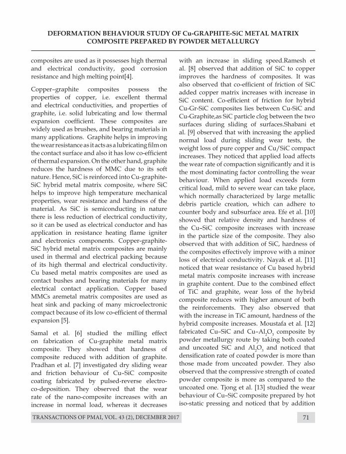
TRANSACTIONS OF PMAI, VOL. 43 (2), DECEMBER 2017 71
DEFORMATION BEHAVIOUR STUDY OF Cu-GRAPHITE-SiC METAL MATRIx COMPOSITE PREPARED BY POWDER METALLURGY
composites are used as it possesses high thermal and electrical conductivity, good corrosion resistance and high melting point[4].
Copper–graphite composites possess the properties of copper, i.e. excellent thermal and electrical conductivities, and properties of graphite, i.e. solid lubricating and low thermal expansion coefficient. These composites are widely used as brushes, and bearing materials in many applications. Graphite helps in improving the wear resistance as it acts as a lubricating film on the contact surface and also it has low co-efficient of thermal expansion. On the other hand, graphite reduces the hardness of MMC due to its soft nature. Hence, SiC is reinforced into Cu-graphite-SiC hybrid metal matrix composite, where SiC helps to improve high temperature mechanical properties, wear resistance and hardness of the material. As SiC is semiconducting in nature there is less reduction of electrical conductivity, so it can be used as electrical conductor and has application in resistance heating flame igniter and electronics components. Copper-graphite-SiC hybrid metal matrix composites are mainly used in thermal and electrical packing because of its high thermal and electrical conductivity. Cu based metal matrix composites are used as contact bushes and bearing materials for many electrical contact application. Copper based MMCs aremetal matrix composites are used as heat sink and packing of many microelectronic compact because of its low co-efficient of thermal expansion [5].
Samal et al. [6] studied the milling effect on fabrication of Cu-graphite metal matrix composite. They showed that hardness of composite reduced with addition of graphite. Pradhan et al. [7] investigated dry sliding wear and friction behaviour of Cu–SiC composite coating fabricated by pulsed-reverse electro-co-deposition. They observed that the wear rate of the nano-composite increases with an increase in normal load, whereas it decreases
with an increase in sliding speed.Ramesh et al. [8] observed that addition of SiC to copper improves the hardness of composites. It was also observed that co-efficient of friction of SiC added copper matrix increases with increase in SiC content. Co-efficient of friction for hybrid Cu-Gr-SiC composites lies between Cu-SiC and Cu-Graphite,as SiC particle clog between the two surfaces during sliding of surfaces.Shabani et al. [9] observed that with increasing the applied normal load during sliding wear tests, the weight loss of pure copper and Cu/SiC compact increases. They noticed that applied load affects the wear rate of compaction significantly and it is the most dominating factor controlling the wear behaviour. When applied load exceeds form critical load, mild to severe wear can take place, which normally characterized by large metallic debris particle creation, which can adhere to counter body and subsurface area. Efe et al. [10] showed that relative density and hardness of the Cu–SiC composite increases with increase in the particle size of the composite. They also observed that with addition of SiC, hardness of the composites effectively improve with a minor loss of electrical conductivity. Nayak et al. [11] noticed that wear resistance of Cu based hybrid metal matrix composite increases with increase in graphite content. Due to the combined effect of TiC and graphite, wear loss of the hybrid composite reduces with higher amount of both the reinforcements. They also observed that with the increase in TiC amount, hardness of the hybrid composite increases. Moustafa et al. [12] fabricated Cu–SiC and Cu–Al2O3 composite by powder metallurgy route by taking both coated and uncoated SiC and Al2O3 and noticed that densification rate of coated powder is more than those made from uncoated powder. They also observed that the compressive strength of coated powder composite is more as compared to the uncoated one. Tjong et al. [13] studied the wear behaviour of Cu–SiC composite prepared by hot iso-static pressing and noticed that by addition
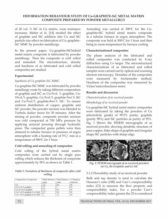
TRANSACTIONS OF PMAI, VOL. 43 (2), DECEMBER 201772
of 20 vol. % SiC in Cu matrix, wear resistance increases. Meher et al. [14] studied the effect of graphite and SiC addition into Cu and SiC particle size effect on fabrication of Cu–graphite–SiC MMC by powder metallurgy.
In the present paper, Cu-graphite-SiChubrid metal matrix composite is fabricated by powder metallurgy. Then the composite is cold rolled and annealed. The microstructure, density and hardness of as fabricated and cold rolled composites are studied.
Experimental Synthesis of Cu-graphite-SiC MMCCu-graphite-SiC MMC was fabricated by powder metallurgy route by taking different composition of graphite and SiC as Cu-5vol. % graphite, Cu-10vol.% graphite, Cu-5vol.% graphite-5wt.% SiC and Cu-5vol.% graphite-8wt.% SiC. To ensure uniform distribution of copper, graphite and SiC powder, the powder mixture was blended in Turbula shaker mixer for 30 minutes. After the mixing of powder, composite powder mixture was cold compacted at 700 MPa pressure by applying uniaxial pressing through hydraulic press. The compacted green pellets were then sintered in tubular furnace in presence of argon atmosphere with a heating rate of 5oC/ min at a temperature of 900oC for 1 hour.
Cold rolling and annealing of compositesCold rolling of the hybrid metal matrix composites were carried out by single pass rolling which reduces the thickness of composite approximately by 50% as shown in Table 1.
Annealing was carried at 300oC for the Cu-graphite-SiC hybrid metal matrix composite in a tubular furnace in argon atmosphere. The composite was held at 300oC for 1 hour and then bring to room temperature by furnace cooling.
Characterizationof compositesThe phase analysis of the fabricated and rolled composites was conducted by X-ray diffraction using Co target. The microstructural characterizations of as fabricated and rolled samples were carried out by optical and scanning electron microscopy. Densities of the composites were measured by Archemedes method. Hardness of the composites was measured by Vicker’smicrohardness tester.
Results and discussionCharacterization of as received powderMorphology of as received powderCu-graphite-SiC hybrid metal matrix composites were fabricated by taking the powders of Cu (electrolytic grade) of 99.5% purity, graphite (purity 98%) and SiC particles as purity of 95%. Fig. 1 Shows the FESEM micrographs of as received powder, showing dendritic structure of pure copper, flake shape of graphite and irregular shape SiC particles with sharp edge.
3.1.2 Flowability study of as received powderBulk and tap density is used to calculate the Hausner’s ratio (HR) and Carr’s compressibility index (CI) to measure the flow property and compressibility index. For a powder Carr’s compressibility index greater the 25 is considered
DEFORMATION BEHAVIOUR STUDY OF Cu-GRAPHITE-SiC METAL MATRIx COMPOSITE PREPARED BY POWDER METALLURGY
Table 1: Variation of thickness of composite after cold rolling
Fig. 1: FESEM micrograph of as received powders (a) Cu, (b) Graphite and (c) SiC
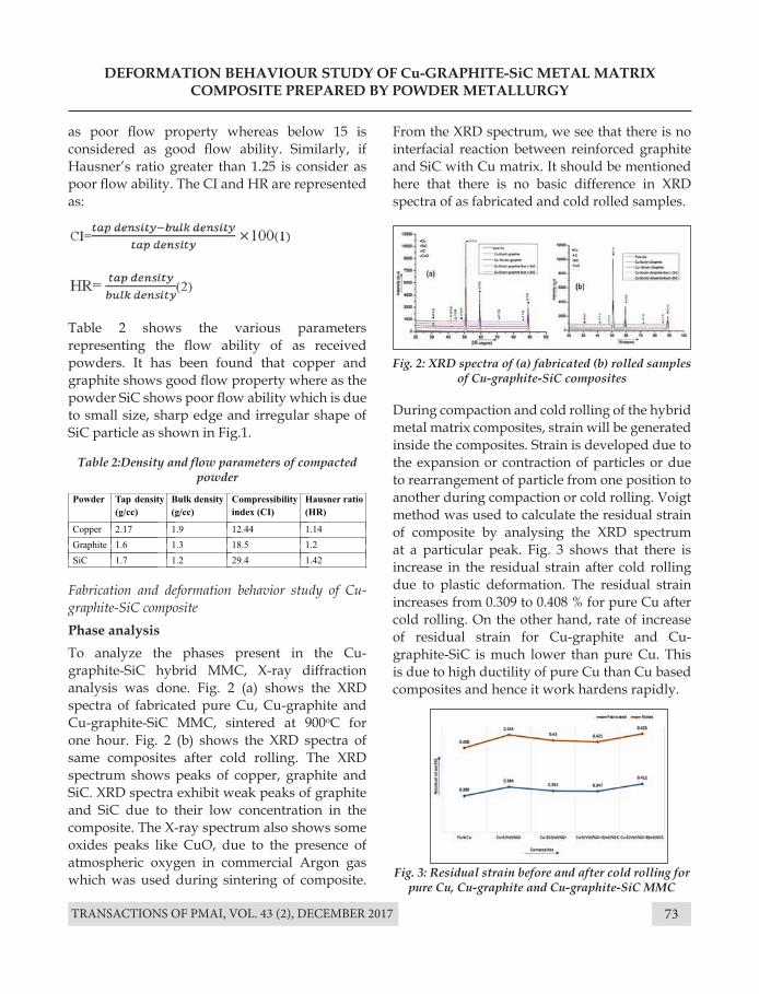
TRANSACTIONS OF PMAI, VOL. 43 (2), DECEMBER 2017 73
DEFORMATION BEHAVIOUR STUDY OF Cu-GRAPHITE-SiC METAL MATRIx COMPOSITE PREPARED BY POWDER METALLURGY
Table 2:Density and flow parameters of compacted powder
Fig. 2: XRD spectra of (a) fabricated (b) rolled samples of Cu-graphite-SiC composites
Fig. 3: Residual strain before and after cold rolling for pure Cu, Cu-graphite and Cu-graphite-SiC MMC
as poor flow property whereas below 15 is considered as good flow ability. Similarly, if Hausner’s ratio greater than 1.25 is consider as poor flow ability. The CI and HR are represented as:
Table 2 shows the various parameters representing the flow ability of as received powders. It has been found that copper and graphite shows good flow property where as the powder SiC shows poor flow ability which is due to small size, sharp edge and irregular shape of SiC particle as shown in Fig.1.
Fabrication and deformation behavior study of Cu-graphite-SiC compositePhase analysisTo analyze the phases present in the Cu-graphite-SiC hybrid MMC, X-ray diffraction analysis was done. Fig. 2 (a) shows the XRD spectra of fabricated pure Cu, Cu-graphite and Cu-graphite-SiC MMC, sintered at 900oC for one hour. Fig. 2 (b) shows the XRD spectra of same composites after cold rolling. The XRD spectrum shows peaks of copper, graphite and SiC. XRD spectra exhibit weak peaks of graphite and SiC due to their low concentration in the composite. The X-ray spectrum also shows some oxides peaks like CuO, due to the presence of atmospheric oxygen in commercial Argon gas which was used during sintering of composite.
From the XRD spectrum, we see that there is no interfacial reaction between reinforced graphite and SiC with Cu matrix. It should be mentioned here that there is no basic difference in XRD spectra of as fabricated and cold rolled samples.
During compaction and cold rolling of the hybrid metal matrix composites, strain will be generated inside the composites. Strain is developed due to the expansion or contraction of particles or due to rearrangement of particle from one position to another during compaction or cold rolling. Voigt method was used to calculate the residual strain of composite by analysing the XRD spectrum at a particular peak. Fig. 3 shows that there is increase in the residual strain after cold rolling due to plastic deformation. The residual strain increases from 0.309 to 0.408 % for pure Cu after cold rolling. On the other hand, rate of increase of residual strain for Cu-graphite and Cu-graphite-SiC is much lower than pure Cu. This is due to high ductility of pure Cu than Cu based composites and hence it work hardens rapidly.
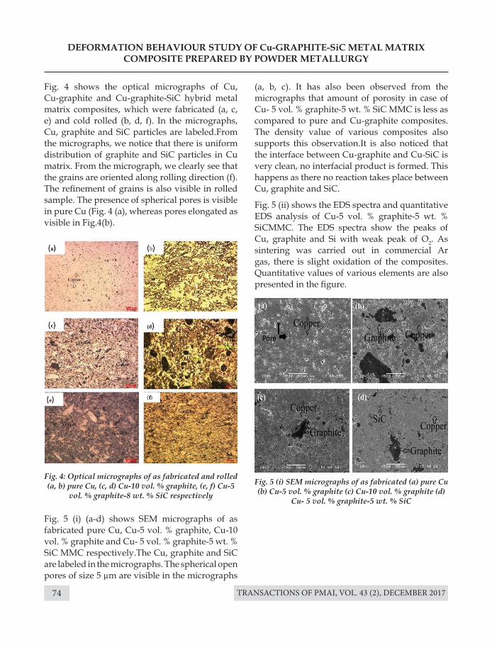
TRANSACTIONS OF PMAI, VOL. 43 (2), DECEMBER 201774
DEFORMATION BEHAVIOUR STUDY OF Cu-GRAPHITE-SiC METAL MATRIx COMPOSITE PREPARED BY POWDER METALLURGY
Fig. 4 shows the optical micrographs of Cu, Cu-graphite and Cu-graphite-SiC hybrid metal matrix composites, which were fabricated (a, c, e) and cold rolled (b, d, f). In the micrographs, Cu, graphite and SiC particles are labeled.From the micrographs, we notice that there is uniform distribution of graphite and SiC particles in Cu matrix. From the micrograph, we clearly see that the grains are oriented along rolling direction (f). The refinement of grains is also visible in rolled sample. The presence of spherical pores is visible in pure Cu (Fig. 4 (a), whereas pores elongated as visible in Fig.4(b).
Fig. 5 (i) (a-d) shows SEM micrographs of as fabricated pure Cu, Cu-5 vol. % graphite, Cu-10 vol. % graphite and Cu- 5 vol. % graphite-5 wt. % SiC MMC respectively.The Cu, graphite and SiC are labeled in the micrographs. The spherical open pores of size 5 µm are visible in the micrographs
Fig. 4: Optical micrographs of as fabricated and rolled (a, b) pure Cu, (c, d) Cu-10 vol. % graphite, (e, f) Cu-5
vol. % graphite-8 wt. % SiC respectively
Fig. 5 (i) SEM micrographs of as fabricated (a) pure Cu (b) Cu-5 vol. % graphite (c) Cu-10 vol. % graphite (d)
Cu- 5 vol. % graphite-5 wt. % SiC
(a, b, c). It has also been observed from the micrographs that amount of porosity in case of Cu- 5 vol. % graphite-5 wt. % SiC MMC is less as compared to pure and Cu-graphite composites. The density value of various composites also supports this observation.It is also noticed that the interface between Cu-graphite and Cu-SiC is very clean, no interfacial product is formed. This happens as there no reaction takes place between Cu, graphite and SiC.
Fig. 5 (ii) shows the EDS spectra and quantitative EDS analysis of Cu-5 vol. % graphite-5 wt. % SiCMMC. The EDS spectra show the peaks of Cu, graphite and Si with weak peak of O2. As sintering was carried out in commercial Ar gas, there is slight oxidation of the composites. Quantitative values of various elements are also presented in the figure.
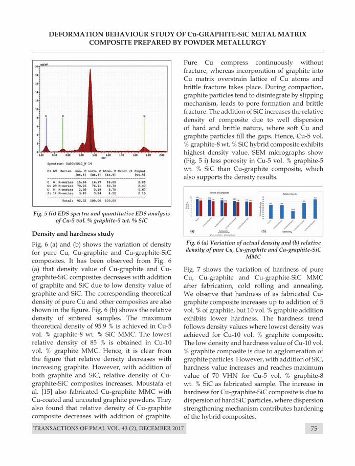
TRANSACTIONS OF PMAI, VOL. 43 (2), DECEMBER 2017 75
DEFORMATION BEHAVIOUR STUDY OF Cu-GRAPHITE-SiC METAL MATRIx COMPOSITE PREPARED BY POWDER METALLURGY
Fig. 5 (ii) EDS spectra and quantitative EDS analysis of Cu-5 vol. % graphite-5 wt. % SiC
Fig. 6 (a) Variation of actual density and (b) relative density of pure Cu, Cu-graphite and Cu-graphite-SiC
MMC
Density and hardness study Fig. 6 (a) and (b) shows the variation of density for pure Cu, Cu-graphite and Cu-graphite-SiC composites. It has been observed from Fig. 6 (a) that density value of Cu-graphite and Cu-graphite-SiC composites decreases with addition of graphite and SiC due to low density value of graphite and SiC. The corresponding theoretical density of pure Cu and other composites are also shown in the figure. Fig. 6 (b) shows the relative density of sintered samples. The maximum theoretical density of 95.9 % is achieved in Cu-5 vol. % graphite-8 wt. % SiC MMC. The lowest relative density of 85 % is obtained in Cu-10 vol. % graphite MMC. Hence, it is clear from the figure that relative density decreases with increasing graphite. However, with addition of both graphite and SiC, relative density of Cu-graphite-SiC composites increases. Moustafa et al. [15] also fabricated Cu-graphite MMC with Cu-coated and uncoated graphite powders. They also found that relative density of Cu-graphite composite decreases with addition of graphite.
Pure Cu compress continuously without fracture, whereas incorporation of graphite into Cu matrix overstrain lattice of Cu atoms and brittle fracture takes place. During compaction, graphite particles tend to disintegrate by slipping mechanism, leads to pore formation and brittle fracture. The addition of SiC increases the relative density of composite due to well dispersion of hard and brittle nature, where soft Cu and graphite particles fill the gaps. Hence, Cu-5 vol. % graphite-8 wt. % SiC hybrid composite exhibits highest density value. SEM micrographs show (Fig. 5 i) less porosity in Cu-5 vol. % graphite-5 wt. % SiC than Cu-graphite composite, which also supports the density results.
Fig. 7 shows the variation of hardness of pure Cu, Cu-graphite and Cu-graphite-SiC MMC after fabrication, cold rolling and annealing. We observe that hardness of as fabricated Cu-graphite composite increases up to addition of 5 vol. % of graphite, but 10 vol. % graphite addition exhibits lower hardness. The hardness trend follows density values where lowest density was achieved for Cu-10 vol. % graphite composite. The low density and hardness value of Cu-10 vol. % graphite composite is due to agglomeration of graphite particles. However, with addition of SiC, hardness value increases and reaches maximum value of 70 VHN for Cu-5 vol. % graphite-8 wt. % SiC as fabricated sample. The increase in hardness for Cu-graphite-SiC composite is due to dispersion of hard SiC particles, where dispersion strengthening mechanism contributes hardening of the hybrid composites.
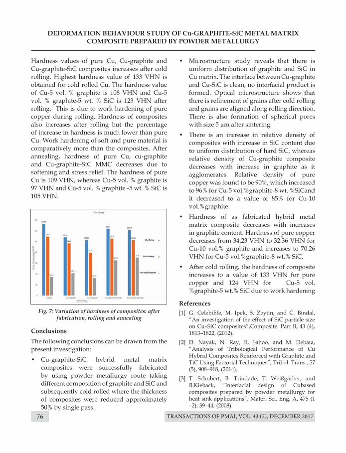
TRANSACTIONS OF PMAI, VOL. 43 (2), DECEMBER 201776
Hardness values of pure Cu, Cu-graphite and Cu-graphite-SiC composites increases after cold rolling. Highest hardness value of 133 VHN is obtained for cold rolled Cu. The hardness value of Cu-5 vol. % graphite is 108 VHN and Cu-5 vol. % graphite-5 wt. % SiC is 123 VHN after rolling. This is due to work hardening of pure copper during rolling. Hardness of composites also increases after rolling but the percentage of increase in hardness is much lower than pure Cu. Work hardening of soft and pure material is comparatively more than the composites. After annealing, hardness of pure Cu, cu-graphite and Cu-graphite-SiC MMC decreases due to softening and stress relief. The hardness of pure Cu is 109 VHN, whereas Cu-5 vol. % graphite is 97 VHN and Cu-5 vol. % graphite -5 wt. % SiC is 105 VHN.
ConclusionsThe following conclusions can be drawn from the present investigation:• Cu-graphite-SiC hybrid metal matrix
composites were successfully fabricated by using powder metallurgy route taking different composition of graphite and SiC and subsequently cold rolled where the thickness of composites were reduced approximately 50% by single pass.
DEFORMATION BEHAVIOUR STUDY OF Cu-GRAPHITE-SiC METAL MATRIx COMPOSITE PREPARED BY POWDER METALLURGY
Fig. 7: Variation of hardness of composites: after fabrication, rolling and annealing
• Microstructure study reveals that there is uniform distribution of graphite and SiC in Cu matrix. The interface between Cu-graphite and Cu-SiC is clean, no interfacial product is formed. Optical microstructure shows that there is refinement of grains after cold rolling and grains are aligned along rolling direction. There is also formation of spherical pores with size 5 µm after sintering.
• There is an increase in relative density of composites with increase in SiC content due to uniform distribution of hard SiC, whereas relative density of Cu-graphite composite decreases with increase in graphite as it agglomerates. Relative density of pure copper was found to be 90%, which increased to 96% for Cu-5 vol.%graphite-8 wt. %SiCand it decreased to a value of 85% for Cu-10 vol.%graphite.
• Hardness of as fabricated hybrid metal matrix composite decreases with increases in graphite content. Hardness of pure copper decreases from 34.23 VHN to 32.36 VHN for Cu-10 vol.% graphite and increases to 70.26 VHN for Cu-5 vol.%graphite-8 wt.% SiC.
• After cold rolling, the hardness of composite increases to a value of 133 VHN for pure copper and 124 VHN for Cu-5 vol. %graphite-5 wt.% SiC due to work hardening
References[1] G. CelebiEfe, M. Ipek, S. Zeytin, and C. Bindal,
“An investigation of the effect of SiC particle size on Cu–SiC composites”,Composite. Part B, 43 (4), 1813–1822, (2012).
[2] D. Nayak, N. Ray, R. Sahoo, and M. Debata, “Analysis of Tribological Performance of Cu Hybrid Composites Reinforced with Graphite and TiC Using Factorial Techniques”, Tribol. Trans., 57 (5), 908–918, (2014).
[3] T. Schubert, B. Trindade, T. Weißgärber, and B.Kieback, “Interfacial design of Cubased composites prepared by powder metallurgy for heat sink applications”, Mater. Sci. Eng. A, 475 (1 –2), 39–44, (2008).
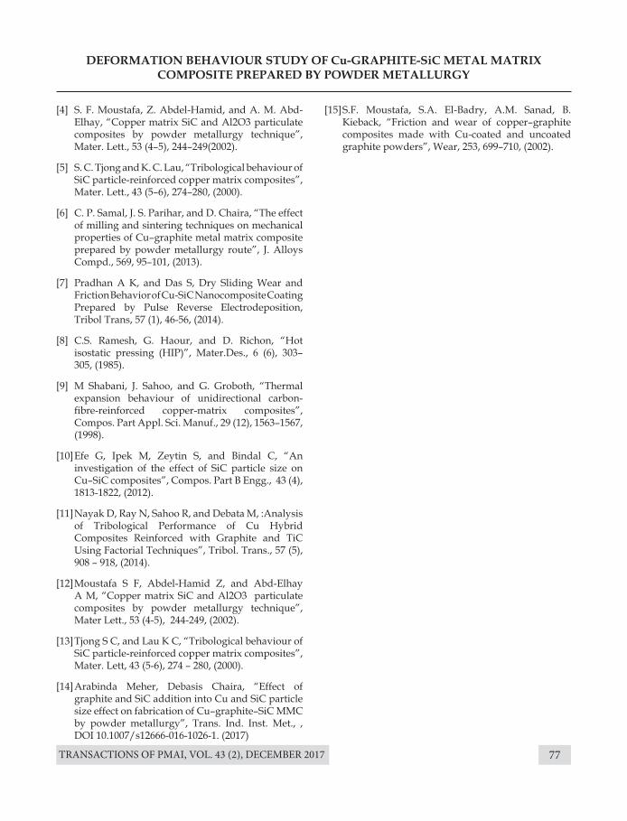
TRANSACTIONS OF PMAI, VOL. 43 (2), DECEMBER 2017 77
DEFORMATION BEHAVIOUR STUDY OF Cu-GRAPHITE-SiC METAL MATRIx COMPOSITE PREPARED BY POWDER METALLURGY
[4] S. F. Moustafa, Z. Abdel-Hamid, and A. M. Abd-Elhay, “Copper matrix SiC and Al2O3 particulate composites by powder metallurgy technique”, Mater. Lett., 53 (4–5), 244–249(2002).
[5] S. C. Tjong and K. C. Lau, “Tribological behaviour of SiC particle-reinforced copper matrix composites”, Mater. Lett., 43 (5–6), 274–280, (2000).
[6] C. P. Samal, J. S. Parihar, and D. Chaira, “The effect of milling and sintering techniques on mechanical properties of Cu–graphite metal matrix composite prepared by powder metallurgy route”, J. Alloys Compd., 569, 95–101, (2013).
[7] Pradhan A K, and Das S, Dry Sliding Wear and Friction Behavior of Cu-SiC Nanocomposite Coating Prepared by Pulse Reverse Electrodeposition, Tribol Trans, 57 (1), 46-56, (2014).
[8] C.S. Ramesh, G. Haour, and D. Richon, “Hot isostatic pressing (HIP)”, Mater.Des., 6 (6), 303–305, (1985).
[9] M Shabani, J. Sahoo, and G. Groboth, “Thermal expansion behaviour of unidirectional carbon-fibre-reinforced copper-matrix composites”, Compos. Part Appl. Sci. Manuf., 29 (12), 1563–1567, (1998).
[10] Efe G, Ipek M, Zeytin S, and Bindal C, “An investigation of the effect of SiC particle size on Cu–SiC composites”, Compos. Part B Engg., 43 (4), 1813-1822, (2012).
[11] Nayak D, Ray N, Sahoo R, and Debata M, :Analysis of Tribological Performance of Cu Hybrid Composites Reinforced with Graphite and TiC Using Factorial Techniques”, Tribol. Trans., 57 (5), 908 – 918, (2014).
[12] Moustafa S F, Abdel-Hamid Z, and Abd-Elhay A M, “Copper matrix SiC and Al2O3 particulate composites by powder metallurgy technique”, Mater Lett., 53 (4-5), 244-249, (2002).
[13] Tjong S C, and Lau K C, “Tribological behaviour of SiC particle-reinforced copper matrix composites”, Mater. Lett, 43 (5-6), 274 – 280, (2000).
[14] Arabinda Meher, Debasis Chaira, “Effect of graphite and SiC addition into Cu and SiC particle size effect on fabrication of Cu–graphite–SiC MMC by powder metallurgy”, Trans. Ind. Inst. Met., , DOI 10.1007/s12666-016-1026-1. (2017)
[15] S.F. Moustafa, S.A. El-Badry, A.M. Sanad, B. Kieback, “Friction and wear of copper–graphite composites made with Cu-coated and uncoated graphite powders”, Wear, 253, 699–710, (2002).
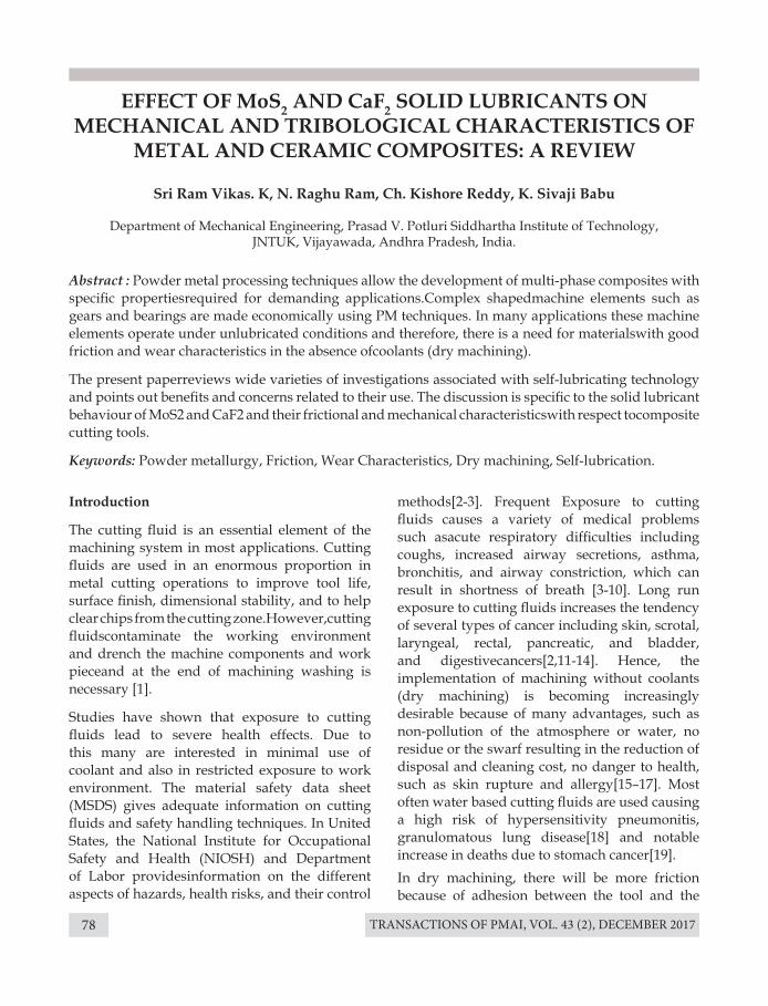
TRANSACTIONS OF PMAI, VOL. 43 (2), DECEMBER 201778
EFFECT OF MoS2 AND CaF2 SOLID LUBRICANTS ON MECHANICAL AND TRIBOLOGICAL CHARACTERISTICS OF
METAL AND CERAMIC COMPOSITES: A REVIEW
Sri Ram Vikas. K, N. Raghu Ram, Ch. Kishore Reddy, K. Sivaji Babu
Department of Mechanical Engineering, Prasad V. Potluri Siddhartha Institute of Technology, JNTUK, Vijayawada, Andhra Pradesh, India.
Introduction
The cutting fluid is an essential element of the machining system in most applications. Cutting fluids are used in an enormous proportion in metal cutting operations to improve tool life, surface finish, dimensional stability, and to help clear chips from the cutting zone.However,cutting fluidscontaminate the working environment and drench the machine components and work pieceand at the end of machining washing is necessary [1].
Studies have shown that exposure to cutting fluids lead to severe health effects. Due to this many are interested in minimal use of coolant and also in restricted exposure to work environment. The material safety data sheet (MSDS) gives adequate information on cutting fluids and safety handling techniques. In United States, the National Institute for Occupational Safety and Health (NIOSH) and Department of Labor providesinformation on the different aspects of hazards, health risks, and their control
Abstract : Powder metal processing techniques allow the development of multi-phase composites with specific propertiesrequired for demanding applications.Complex shapedmachine elements such as gears and bearings are made economically using PM techniques. In many applications these machine elements operate under unlubricated conditions and therefore, there is a need for materialswith good friction and wear characteristics in the absence ofcoolants (dry machining).
The present paperreviews wide varieties of investigations associated with self-lubricating technology and points out benefits and concerns related to their use. The discussion is specific to the solid lubricant behaviour of MoS2 and CaF2 and their frictional and mechanical characteristicswith respect tocomposite cutting tools.
Keywords: Powder metallurgy, Friction, Wear Characteristics, Dry machining, Self-lubrication.
methods[2-3]. Frequent Exposure to cutting fluids causes a variety of medical problems such asacute respiratory difficulties including coughs, increased airway secretions, asthma, bronchitis, and airway constriction, which can result in shortness of breath [3-10]. Long run exposure to cutting fluids increases the tendency of several types of cancer including skin, scrotal, laryngeal, rectal, pancreatic, and bladder, and digestivecancers[2,11-14]. Hence, the implementation of machining without coolants (dry machining) is becoming increasingly desirable because of many advantages, such as non-pollution of the atmosphere or water, no residue or the swarf resulting in the reduction of disposal and cleaning cost, no danger to health, such as skin rupture and allergy[15–17]. Most often water based cutting fluids are used causing a high risk of hypersensitivity pneumonitis, granulomatous lung disease[18] and notable increase in deaths due to stomach cancer[19].In dry machining, there will be more friction because of adhesion between the tool and the
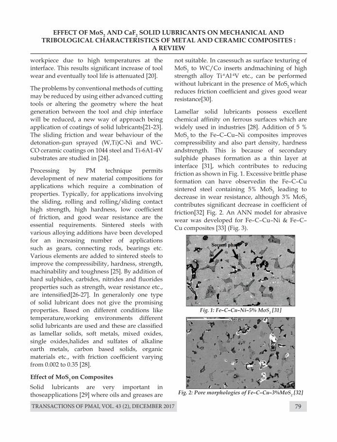
TRANSACTIONS OF PMAI, VOL. 43 (2), DECEMBER 2017 79
workpiece due to high temperatures at the interface. This results significant increase of tool wear and eventually tool life is attenuated [20].
The problems by conventional methods of cutting may be reduced by using either advanced cutting tools or altering the geometry where the heat generation between the tool and chip interface will be reduced, a new way of approach being application of coatings of solid lubricants[21-23].The sliding friction and wear behaviour of the detonation-gun sprayed (W,Ti)C-Ni and WC-CO ceramic coatings on 1044 steel and Ti-6A1-4V substrates are studied in [24].
Processing by PM technique permits development of new material compositions for applications which require a combination of properties. Typically, for applications involving the sliding, rolling and rolling/sliding contact high strength, high hardness, low coefficient of friction, and good wear resistance are the essential requirements. Sintered steels with various alloying additions have been developed for an increasing number of applications such as gears, connecting rods, bearings etc. Various elements are added to sintered steels to improve the compressibility, hardness, strength, machinability and toughness [25]. By addition of hard sulphides, carbides, nitrides and fluorides properties such as strength, wear resistance etc., are intensified[26-27]. In generalonly one type of solid lubricant does not give the promising properties. Based on different conditions like temperature,working environments different solid lubricants are used and these are classified as lamellar solids, soft metals, mixed oxides, single oxides,halides and sulfates of alkaline earth metals, carbon based solids, organic materials etc., with friction coefficient varying from 0.002 to 0.35 [28].
Effect of MoS2 on CompositesSolid lubricants are very important in thoseapplications [29] where oils and greases are
EFFECT OF MoS2 AND CaF2 SOLID LUBRICANTS ON MECHANICAL AND TRIBOLOGICAL CHARACTERISTICS OF METAL AND CERAMIC COMPOSITES :
A REVIEW
not suitable. In casessuch as surface texturing of MoS2 to WC/Co inserts andmachining of high strength alloy Ti-6Al-4V etc., can be performed without lubricant in the presence of MoS2 which reduces friction coefficient and gives good wear resistance[30].
Lamellar solid lubricants possess excellent chemical affinity on ferrous surfaces which are widely used in industries [28]. Addition of 5 % MoS2 to the Fe–C–Cu–Ni composites improves compressibility and also part density, hardness andstrength. This is because of secondary sulphide phases formation as a thin layer at interface [31], which contributes to reducing friction as shown in Fig. 1. Excessive brittle phase formation can have observedin the Fe–C–Cu sintered steel containing 5% MoS2 leading to decrease in wear resistance, although 3% MoS2 contributes significant decrease in coefficient of friction[32] Fig. 2. An ANN model for abrasive wear was developed for Fe–C–Cu–Ni & Fe–C–Cu composites [33] (Fig. 3).
Fig. 1: Fe–C–Cu–Ni–5% MoS2 [31]
Fig. 2: Pore morphologies of Fe–C–Cu–3%MoS2 [32]
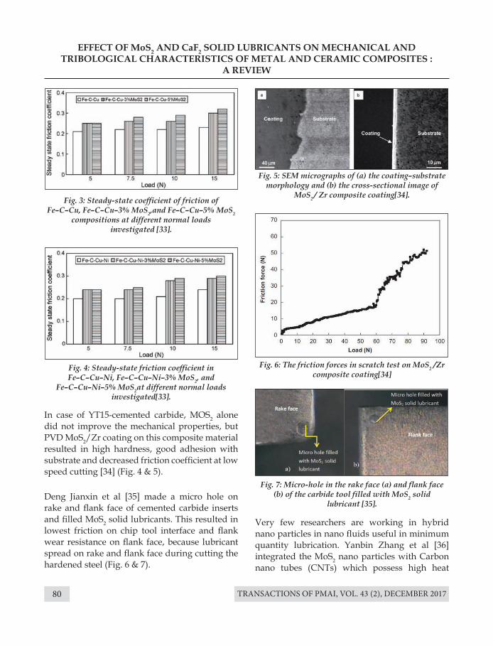
TRANSACTIONS OF PMAI, VOL. 43 (2), DECEMBER 201780
EFFECT OF MoS2 AND CaF2 SOLID LUBRICANTS ON MECHANICAL AND TRIBOLOGICAL CHARACTERISTICS OF METAL AND CERAMIC COMPOSITES :
A REVIEW
Fig. 3: Steady-state coefficient of friction of Fe–C–Cu, Fe–C–Cu–3% MoS2,and Fe–C–Cu–5% MoS2
compositions at different normal loads investigated [33].
Fig. 4: Steady-state friction coefficient in Fe–C–Cu–Ni, Fe–C–Cu–Ni–3% MoS2, and
Fe–C–Cu–Ni–5% MoS2at different normal loads investigated[33].
Fig. 5: SEM micrographs of (a) the coating–substrate morphology and (b) the cross-sectional image of
MoS2 / Zr composite coating[34].
Fig. 6: The friction forces in scratch test on MoS2 /Zr composite coating[34]
Fig. 7: Micro-hole in the rake face (a) and flank face (b) of the carbide tool filled with MoS2 solid
lubricant [35].
In case of YT15-cemented carbide, MOS2 alone did not improve the mechanical properties, but PVD MoS2/Zr coating on this composite material resulted in high hardness, good adhesion with substrate and decreased friction coefficient at low speed cutting [34] (Fig. 4 & 5).
Deng Jianxin et al [35] made a micro hole on rake and flank face of cemented carbide inserts and filled MoS2 solid lubricants. This resulted in lowest friction on chip tool interface and flank wear resistance on flank face, because lubricant spread on rake and flank face during cutting the hardened steel (Fig. 6 & 7).
Very few researchers are working in hybrid nano particles in nano fluids useful in minimum quantity lubrication. Yanbin Zhang et al [36] integrated the MoS2 nano particles with Carbon nano tubes (CNTs) which possess high heat
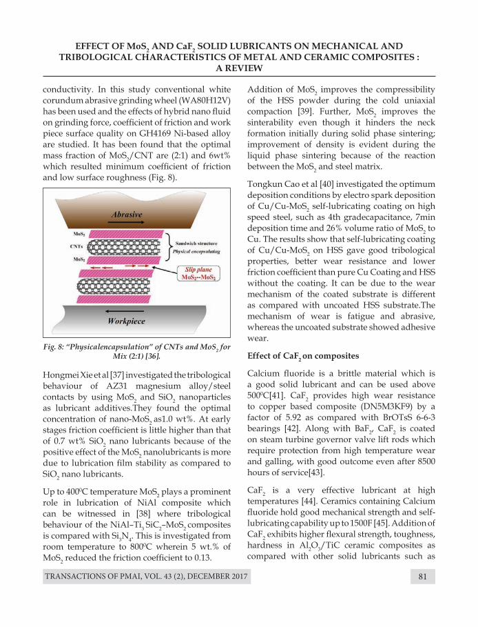
TRANSACTIONS OF PMAI, VOL. 43 (2), DECEMBER 2017 81
EFFECT OF MoS2 AND CaF2 SOLID LUBRICANTS ON MECHANICAL AND TRIBOLOGICAL CHARACTERISTICS OF METAL AND CERAMIC COMPOSITES :
A REVIEW
Fig. 8: “Physicalencapsulation” of CNTs and MoS2 for Mix (2:1) [36].
conductivity. In this study conventional white corundum abrasive grinding wheel (WA80H12V) has been used and the effects of hybrid nano fluid on grinding force, coefficient of friction and work piece surface quality on GH4169 Ni-based alloy are studied. It has been found that the optimal mass fraction of MoS2/CNT are (2:1) and 6wt% which resulted minimum coefficient of friction and low surface roughness (Fig. 8).
Hongmei Xie et al [37] investigated the tribological behaviour of AZ31 magnesium alloy/steel contacts by using MoS2 and SiO2 nanoparticles as lubricant additives.They found the optimal concentration of nano-MoS2 as1.0 wt%. At early stages friction coefficient is little higher than that of 0.7 wt% SiO2 nano lubricants because of the positive effect of the MoS2 nanolubricants is more due to lubrication film stability as compared to SiO2 nano lubricants.
Up to 4000C temperature MoS2 plays a prominent role in lubrication of NiAl composite which can be witnessed in [38] where tribological behaviour of the NiAl–Ti3 SiC2–MoS2 composites is compared with Si3N4. This is investigated from room temperature to 8000C wherein 5 wt.% of MoS2 reduced the friction coefficient to 0.13.
Addition of MoS2 improves the compressibility of the HSS powder during the cold uniaxial compaction [39]. Further, MoS2 improves the sinterability even though it hinders the neck formation initially during solid phase sintering; improvement of density is evident during the liquid phase sintering because of the reaction between the MoS2 and steel matrix.
Tongkun Cao et al [40] investigated the optimum deposition conditions by electro spark deposition of Cu/Cu-MoS2 self-lubricating coating on high speed steel, such as 4th gradecapacitance, 7min deposition time and 26% volume ratio of MoS2 to Cu. The results show that self-lubricating coating of Cu/Cu-MoS2 on HSS gave good tribological properties, better wear resistance and lower friction coefficient than pure Cu Coating and HSS without the coating. It can be due to the wear mechanism of the coated substrate is different as compared with uncoated HSS substrate.The mechanism of wear is fatigue and abrasive, whereas the uncoated substrate showed adhesive wear.
Effect of CaF2 on composites
Calcium fluoride is a brittle material which is a good solid lubricant and can be used above 5000C[41]. CaF2 provides high wear resistance to copper based composite (DN5M3KF9) by a factor of 5.92 as compared with BrOTsS 6-6-3 bearings [42]. Along with BaF2, CaF2 is coated on steam turbine governor valve lift rods which require protection from high temperature wear and galling, with good outcome even after 8500 hours of service[43].
CaF2 is a very effective lubricant at high temperatures [44]. Ceramics containing Calcium fluoride hold good mechanical strength and self-lubricating capability up to 1500F [45]. Addition of CaF2 exhibits higher flexural strength, toughness, hardness in Al2O3/TiC ceramic composites as compared with other solid lubricants such as
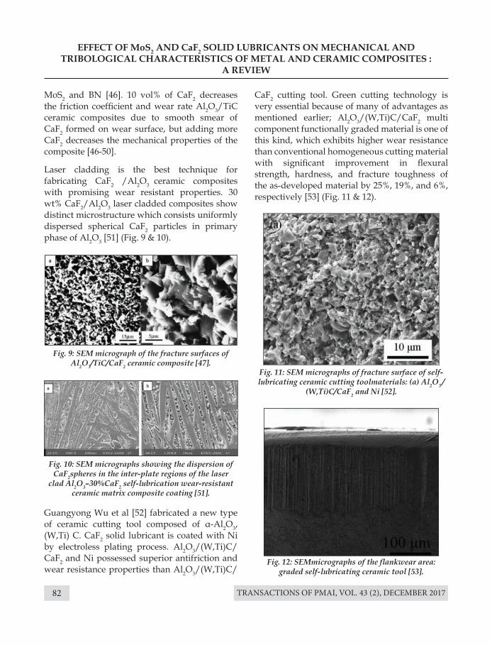
TRANSACTIONS OF PMAI, VOL. 43 (2), DECEMBER 201782
MoS2 and BN [46]. 10 vol% of CaF2 decreases the friction coefficient and wear rate Al2O3/TiC ceramic composites due to smooth smear of CaF2 formed on wear surface, but adding more CaF2 decreases the mechanical properties of the composite [46-50].
Laser cladding is the best technique for fabricating CaF2 /Al2O3 ceramic composites with promising wear resistant properties. 30 wt% CaF2/Al2O3 laser cladded composites show distinct microstructure which consists uniformly dispersed spherical CaF2 particles in primary phase of Al2O3 [51] (Fig. 9 & 10).
Guangyong Wu et al [52] fabricated a new type of ceramic cutting tool composed of α-Al2O3, (W,Ti) C. CaF2 solid lubricant is coated with Ni by electroless plating process. Al2O3/(W,Ti)C/CaF2 and Ni possessed superior antifriction and wear resistance properties than Al2O3/(W,Ti)C/
EFFECT OF MoS2 AND CaF2 SOLID LUBRICANTS ON MECHANICAL AND TRIBOLOGICAL CHARACTERISTICS OF METAL AND CERAMIC COMPOSITES :
A REVIEW
Fig. 9: SEM micrograph of the fracture surfaces of Al2O3/TiC/CaF2 ceramic composite [47].
Fig. 11: SEM micrographs of fracture surface of self-lubricating ceramic cutting toolmaterials: (a) Al2O3 /
(W,Ti)C/CaF2 and Ni [52].
Fig. 12: SEMmicrographs of the flankwear area: graded self-lubricating ceramic tool [53].
Fig. 10: SEM micrographs showing the dispersion of CaF2spheres in the inter-plate regions of the laser
clad Al2O3–30%CaF2 self-lubrication wear-resistant ceramic matrix composite coating [51].
CaF2 cutting tool. Green cutting technology is very essential because of many of advantages as mentioned earlier; Al2O3/(W,Ti)C/CaF2 multi component functionally graded material is one of this kind, which exhibits higher wear resistance than conventional homogeneous cutting material with significant improvement in flexural strength, hardness, and fracture toughness of the as-developed material by 25%, 19%, and 6%, respectively [53] (Fig. 11 & 12).
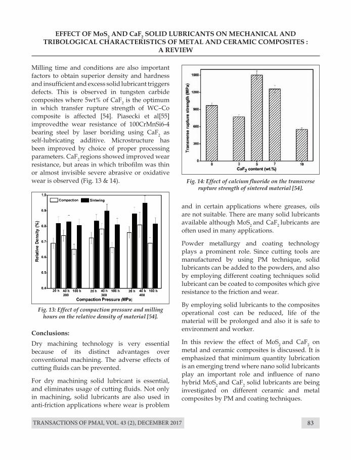
TRANSACTIONS OF PMAI, VOL. 43 (2), DECEMBER 2017 83
EFFECT OF MoS2 AND CaF2 SOLID LUBRICANTS ON MECHANICAL AND TRIBOLOGICAL CHARACTERISTICS OF METAL AND CERAMIC COMPOSITES :
A REVIEW
Fig. 13: Effect of compaction pressure and milling hours on the relative density of material [54].
Fig. 14: Effect of calcium fluoride on the transverse rupture strength of sintered material [54].
Milling time and conditions are also important factors to obtain superior density and hardness and insufficient and excess solid lubricant triggers defects. This is observed in tungsten carbide composites where 5wt% of CaF2 is the optimum in which transfer rupture strength of WC–Co composite is affected [54]. Piasecki et al[55] improvedthe wear resistance of 100CrMnSi6-4 bearing steel by laser boriding using CaF2 as self-lubricating additive. Microstructure has been improved by choice of proper processing parameters. CaF2 regions showed improved wear resistance, but areas in which tribofilm was thin or almost invisible severe abrasive or oxidative wear is observed (Fig. 13 & 14).
Conclusions:Dry machining technology is very essential because of its distinct advantages over conventional machining. The adverse effects of cutting fluids can be prevented.
For dry machining solid lubricant is essential, and eliminates usage of cutting fluids. Not only in machining, solid lubricants are also used in anti-friction applications where wear is problem
and in certain applications where greases, oils are not suitable. There are many solid lubricants available although MoS2 and CaF2 lubricants are often used in many applications.
Powder metallurgy and coating technology plays a prominent role. Since cutting tools are manufactured by using PM technique, solid lubricants can be added to the powders, and also by employing different coating techniques solid lubricant can be coated to composites which give resistance to the friction and wear.
By employing solid lubricants to the composites operational cost can be reduced, life of the material will be prolonged and also it is safe to environment and worker.
In this review the effect of MoS2 and CaF2 on metal and ceramic composites is discussed. It is emphasized that minimum quantity lubrication is an emerging trend where nano solid lubricants play an important role and influence of nano hybrid MoS2 and CaF2 solid lubricants are being investigated on different ceramic and metal composites by PM and coating techniques.
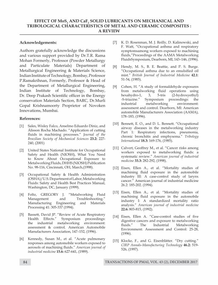
TRANSACTIONS OF PMAI, VOL. 43 (2), DECEMBER 201784
EFFECT OF MoS2 AND CaF2 SOLID LUBRICANTS ON MECHANICAL AND TRIBOLOGICAL CHARACTERISTICS OF METAL AND CERAMIC COMPOSITES :
A REVIEW
Acknowledgements:
Authors gratefully acknowledge the discussions and various support provided by Dr.T.R. Rama Mohan Formerly, Professor (Powder Metallurgy and Particulate Materials) Department of Metallurgical Engineering & Materials Science, Indian Institute of Technology, Bombay, Professor P.Ramakrihnan, Formerly, Professor & Head of the Department of Metallurgical Engineering, Indian Institute of Technology, Bombay, Dr. Deep Prakash Scientific officer in the Energy conservation Materials Section, BARC, Dr.Murli Gopal Krishnamoorty Proprietor of Novoken Innovations, Mumbai.
References:
[1] Sales, Wisley Falco, Anselmo Eduardo Diniz, and Álisson Rocha Machado. “Application of cutting fluids in machining processes.” Journal of the Brazilian Society of Mechanical Sciences 23.2: 227-240, (2001)
[2] United States National Institute for Occupational Safety and Health (NIOSH), What You Need to Know About Occupational Exposure to Metalworking Fluids, DHHS (NIOSH) Publication No. 98-116, Cincinnati, OH, March,(1998).
[3] Occupational Safety & Health Administration (OSHA)/U.S. Department of Labor, Metalworking Fluids: Safety and Health Best Practices Manual, Washington, DC, January (1999).
[4] Foltz, GREGORY J. “Metalworking Fluid Management and Troubleshooting.” Manufacturing Engineering and Materials Processing 41: 305-337 (1994).
[5] Bassett, David JP. “Review of Acute Respiratory Health Effects.” Symposium proceedings: the industrial metalworking environment: assessment & control. American Automobile Manufacturers Association, 147–152, (1996).
[6] Kennedy, Susan M., et al. “Acute pulmonary responses among automobile workers exposed to aerosols of machining fluids.” American journal of industrial medicine 15.6: 627-641, (1989).
[7] K. D. Rosenman, M. J. Reilly, D. Kalinowski, and F. Watt, “Occupational asthma and respiratory symptomsamong workers exposed to machining fluids,”Proceedings of the AAMA Metalworking FluidsSymposium, Dearborn, MI, 143–146, (1996).
[8] Hendy, M. S., B. E. Beattie, and P. S. Burge. “Occupational asthma due to an emulsified oil mist.” British Journal of Industrial Medicine 42.1: 51-54, (1985).
[9] Cohen, H. “A study of formaldehyde exposures from metalworking fluid operations using hexahydro-1, 3, 5-tris (2-hydroxyethyl) -S-triazine.” Symposium proceedings: the industrial metalworking environment: assessment and control. Dearborn, MI: American automobile Manufacturers Association (AAMA), 178–183, (1996).
[10] Bennett, E. O., and D. L. Bennett. “Occupational airway diseases in the metalworking industry Part 1: Respiratory infections, pneumonia, chronic bronchitis and emphysema.” Tribology International 18.3: 169-176, (1985).
[11] Calvert, Geoffrey M., et al. “Cancer risks among workers exposed to metalworking fluids: a systematic review.” American journal of industrial medicine 33.3: 282-292, (1998).
[12] Eisen, Ellen A., et al. “Mortality studies of machining fluid exposure in the automobile industry III: A case-control study of larynx cancer.” American journal of industrial medicine 26.2: 185-202. (1994).
[13] Eisen, Ellen A., et al. “Mortality studies of machining fluid exposure in the automobile industry I: A standardized mortality ratio analysis.” American journal of industrial medicine 22.6: 803-815, (1992).
[14] Eisen, Ellen A. “Case-control studies of five digestive cancers and exposure to metalworking fluids.” The Industrial Metalworking Environment: Assessment and Control: 25-28, (1996).
[15] Klocke, F., and G. Eisenblätter. “Dry cutting.” CIRP Annals-Manufacturing Technology 46.2: 519-526, (1997).
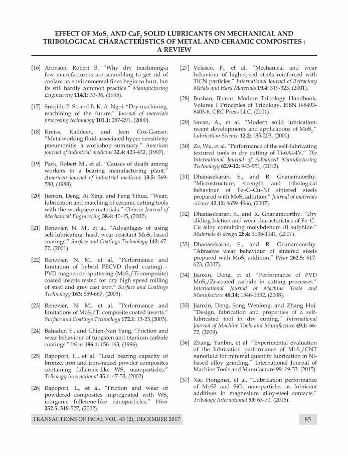
TRANSACTIONS OF PMAI, VOL. 43 (2), DECEMBER 2017 85
EFFECT OF MoS2 AND CaF2 SOLID LUBRICANTS ON MECHANICAL AND TRIBOLOGICAL CHARACTERISTICS OF METAL AND CERAMIC COMPOSITES :
A REVIEW
[16] Aronson, Robert B. “Why dry machining-a few manufacturers are scrambling to get rid of coolant as environmental fines begin to hurt, but its still hardly common practice.” Manufacturing Engineering 114.1: 33-36, (1995).
[17] Sreejith, P. S., and B. K. A. Ngoi. “Dry machining: machining of the future.” Journal of materials processing technology 101.1: 287-291, (2000).
[18] Kreiss, Kathleen, and Jean Cox-Ganser. “Metalworking fluid-associated hyper sensitivity pneumonitis: a workshop summary.” American journal of industrial medicine 32.4: 423-432, (1997).
[19] Park, Robert M., et al. “Causes of death among workers in a bearing manufacturing plant.” American journal of industrial medicine 13.5: 569-580, (1988).
[20] Jianxin, Deng, Ai Xing, and Feng Yihua. “Wear, lubrication and matching of ceramic cutting tools with the workpiece materials.” Chinese Journal of Mechanical Engineering 38.4: 40-45, (2002).
[21] Renevier, N. M., et al. “Advantages of using self-lubricating, hard, wear-resistant MoS2-based coatings.” Surface and Coatings Technology 142: 67-77, (2001).
[22] Renevier, N. M., et al. “Performance and limitation of hybrid PECVD (hard coating)—PVD magnetron sputtering (MoS2/Ti composite) coated inserts tested for dry high speed milling of steel and grey cast iron.” Surface and Coatings Technology 163: 659-667, (2003).
[23] Renevier, N. M., et al. “Performance and limitations of MoS2/Ti composite coated inserts.” Surface and Coatings Technology 172.1: 13-23,(2003).
[24] Bahadur, S., and Chien-Nan Yang. “Friction and wear behaviour of tungsten and titanium carbide coatings.” Wear 196.1: 156-163, (1996).
[25] Rapoport, L., et al. “Load bearing capacity of bronze, iron and iron–nickel powder composites containing fullerene-like WS2 nanoparticles.” Tribology international 35.1: 47-53, (2002).
[26] Rapoport, L., et al. “Friction and wear of powdered composites impregnated with WS2 inorganic fullerene-like nanoparticles.” Wear 252.5: 518-527, (2002).
[27] Velasco, F., et al. “Mechanical and wear behaviour of high-speed steels reinforced with TiCN particles.” International Journal of Refractory Metals and Hard Materials 19.4: 319-323, (2001).
[28] Bushan, Bharat. Modern Tribology Handbook, Volume I Principles of Tribology. ISBN 0-8493-8403-6, CRC Press LLC, (2001).
[29] Savan, A., et al. “Modern solid lubrication: recent developments and applications of MoS2.” Lubrication Science 12.2: 185-203, (2000).
[30] Ze, Wu, et al. “Performance of the self-lubricating textured tools in dry cutting of Ti-6Al-4V.” The International Journal of Advanced Manufacturing Technology 62.9-12: 943-951, (2012).
[31] Dhanasekaran, S., and R. Gnanamoorthy. “Microstructure, strength and tribological behaviour of Fe–C–Cu–Ni sintered steels prepared with MoS2 addition.” Journal of materials science 42.12: 4659-4666, (2007).
[32] Dhanasekaran, S., and R. Gnanamoorthy. “Dry sliding friction and wear characteristics of Fe–C–Cu alloy containing molybdenum di sulphide.” Materials & design 28.4: 1135-1141, (2007).
[33] Dhanasekaran, S., and R. Gnanamoorthy. “Abrasive wear behaviour of sintered steels prepared with MoS2 addition.” Wear 262.5: 617-623, (2007).
[34] Jianxin, Deng, et al. “Performance of PVD MoS2/Zr-coated carbide in cutting processes.” International Journal of Machine Tools and Manufacture 48.14: 1546-1552, (2008).
[35] Jianxin, Deng, Song Wenlong, and Zhang Hui. “Design, fabrication and properties of a self-lubricated tool in dry cutting.” International Journal of Machine Tools and Manufacture 49.1: 66-72, (2009).
[36] Zhang, Yanbin, et al. “Experimental evaluation of the lubrication performance of MoS2/CNT nanofluid for minimal quantity lubrication in Ni-based alloy grinding.” International Journal of Machine Tools and Manufacture 99: 19-33. (2015).
[37] Xie, Hongmei, et al. “Lubrication performance of MoS2 and SiO2 nanoparticles as lubricant additives in magnesium alloy-steel contacts.” Tribology International 93: 63-70, (2016).
TRANSACTIONS OF PMAI, VOL. 43 (2), DECEMBER 201786
EFFECT OF MoS2 AND CaF2 SOLID LUBRICANTS ON MECHANICAL AND TRIBOLOGICAL CHARACTERISTICS OF METAL AND CERAMIC COMPOSITES :
A REVIEW
[38] Shi, Xiaoliang, et al. “Synergetic lubricating effect of MoS2 and Ti3SiC2 on tribological properties of NiAl matrix self-lubricating composites over a wide temperature range.” Materials & Design 55: 93-103, (2014).
[39] Sustarsic, B., et al. “The characteristics of vacuum sintered M3/2 type HSSs with MoS2 addition.” Journal of materials processing technology 143: 98-104, (2003).
[40] Cao, Tongkun, Shuting Lei, and Meng Zhang. “The friction and wear behaviour of Cu/Cu-MoS2 self-lubricating coating prepared by electrospark deposition.” Surface and Coatings Technology 270: 24-32, (2015).
[41] Allam, I. M. “Solid lubricants for applications at elevated temperatures.” Journal of materials science 26.15: 3977-3984, (1991).
[42] Konopka, K., et al. “Effect of CaF2 surface layers on the friction behaviour of copper-based composite.” Powder Metallurgy and Metal Ceramics 51.5-6: 363-367, (2012).
[43] Wang, Wenchao. “Application of a high temperature self-lubricating composite coating on steam turbine components.” Surface and Coatings Technology 177: 12-17, (2004).
[44] Ouyang, J. H., S. Sasaki, and K. Umeda. “The friction and wear characteristics of plasma-sprayed ZrO2-Cr2O3-CaF2 from room temperature to 800° C.” Journal of materials science 36.3: 547-555, (2001).
[45] Sliney, Harold E. “An Investigation of Oxidation-Resistant Solid Lubricant Materials.” Asle Transactions 15.3: 177-183, (1972).
[46] Deng, Jian Xin, Tong Kun Cao, and Jia Lin Sun. “Mechanical properties and microstructure of self-lubricating ceramic cutting tool materials.” Materials Science Forum. Vol. 471: Trans Tech Publications, (2004).
[47] Deng, Jianxin, Tongkun Can, and Junlong Sun. “Microstructure and mechanical properties of hot-pressed Al2O3/TiC ceramic composites with the additions of solid lubricants.” Ceramics International 31.2: 249-256, (2005).
[48] Jianxin, Deng, et al. “Tribological behaviours of hot-pressed Al2O3/TiC ceramic composites with the additions of CaF2 solid lubricants.” Journal of the European Ceramic Society 26.8: 1317-1323, (2006).
[49] Deng, Jianxin, and Tongkun Cao. “Self-lubricating mechanisms via the in situ formed tribofilm of sintered ceramics with CaF2 additions when sliding against hardened steel.” International Journal of Refractory Metals and Hard Materials 25.2: 189-197, (2007).
[50] Yang, Xuefeng, et al. “Dry Sliding Wear Behaviour of Al2O3-TiC Ceramic Composites Added with Solid Lubricant CaF2 by Cold Pressing and Sintering.” Tribology Transactions 58.2: 231-239, (2015).
[51] Wang, H. M., Y. L. Yu, and S. Q. Li. “Microstructure and tribological properties of laser clad CaF2/ Al2O3/ self-lubrication wear-resistant ceramic matrix composite coatings.” Scripta Materialia 47.1: 57-61, (2002).
[52] Wu, Guangyong, et al. “Self-lubricating ceramic cutting tool material with the addition of nickel coated CaF2 solid lubricant powders.” International Journal of Refractory Metals and Hard Materials 56: 51-58, (2016).
[53] Xu, C. H., et al. “Al2O3/(W, Ti)C/CaF2 multi-component graded self-lubricating ceramic cutting tool material.” International Journal of Refractory Metals and Hard Materials 45: 125-129, (2014).
[54] Muthuraja, A., and S. Senthilvelan. “Development of tungsten carbide based self lubricant cutting tool material: preliminary investigation.” International Journal of Refractory Metals and Hard Materials 48: 89-96, (2015).
[55] Piasecki, A., M. Kulka, and M. Kotkowiak. “Wear resistance improvement of 100CrMnSi6-4 bearing steel by laser boriding using CaF2 self-lubricating addition.” Tribology International 97: 173-191, (2016).