Post-Combustion CO2 Capture System for Existing Coal … Library/Events/2015... · 2 Capture System...
30
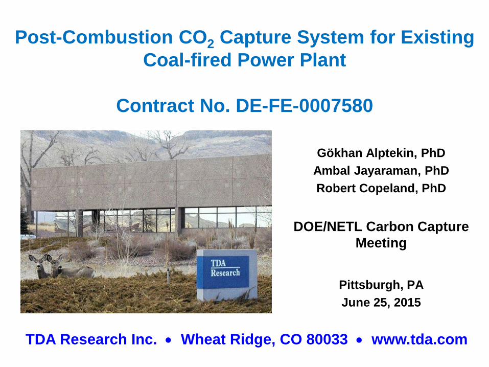
TDA Research Inc. • Wheat Ridge, CO 80033 • www.tda.com Post-Combustion CO 2 Capture System for Existing Coal-fired Power Plant Contract No. DE-FE-0007580 Gökhan Alptekin, PhD Ambal Jayaraman, PhD Robert Copeland, PhD DOE/NETL Carbon Capture Meeting Pittsburgh, PA June 25, 2015
Transcript of Post-Combustion CO2 Capture System for Existing Coal … Library/Events/2015... · 2 Capture System...
TDA Research Inc. • Wheat Ridge, CO 80033 • www.tda.com
Post-Combustion CO2 Capture System for Existing Coal-fired Power Plant
Contract No. DE-FE-0007580
Gökhan Alptekin, PhDAmbal Jayaraman, PhDRobert Copeland, PhD
DOE/NETL Carbon Capture Meeting
Pittsburgh, PAJune 25, 2015
TDAR e s e a r c h
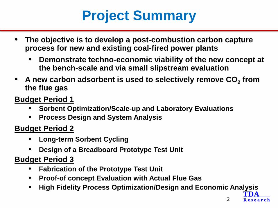
Project Summary• The objective is to develop a post-combustion carbon capture
process for new and existing coal-fired power plants • Demonstrate techno-economic viability of the new concept at
the bench-scale and via small slipstream evaluation• A new carbon adsorbent is used to selectively remove CO2 from
the flue gasBudget Period 1
• Sorbent Optimization/Scale-up and Laboratory Evaluations• Process Design and System Analysis
Budget Period 2• Long-term Sorbent Cycling • Design of a Breadboard Prototype Test Unit
Budget Period 3• Fabrication of the Prototype Test Unit• Proof-of concept Evaluation with Actual Flue Gas• High Fidelity Process Optimization/Design and Economic Analysis
2
TDAR e s e a r c h
Project Partners
3
Project Duration• Start Date = October 1, 2011• End Date = September 30, 2015Budget• Project Budget = $3,375,000• DOE Share = $2,700,000• TDA/Partners Share = $675,000
TDAR e s e a r c h
TDA’s Approach
4
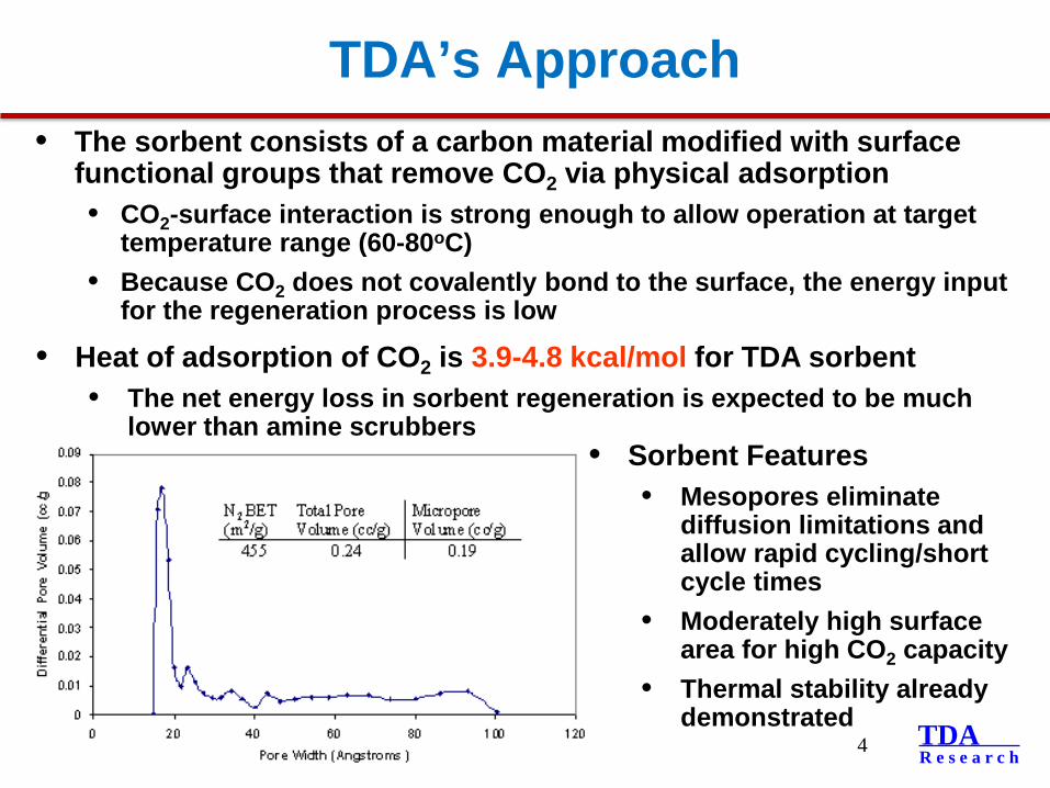
• The sorbent consists of a carbon material modified with surface functional groups that remove CO2 via physical adsorption• CO2-surface interaction is strong enough to allow operation at target
temperature range (60-80oC)• Because CO2 does not covalently bond to the surface, the energy input
for the regeneration process is low
• Heat of adsorption of CO2 is 3.9-4.8 kcal/mol for TDA sorbent• The net energy loss in sorbent regeneration is expected to be much
lower than amine scrubbers • Sorbent Features
• Mesopores eliminate diffusion limitations and allow rapid cycling/short cycle times
• Moderately high surface area for high CO2 capacity
• Thermal stability already demonstrated
TDAR e s e a r c h
Integrated CO2 Capture System
5
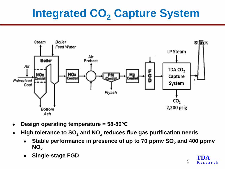
Design operating temperature = 58-80oC High tolerance to SO2 and NOx reduces flue gas purification needs
Stable performance in presence of up to 70 ppmv SO2 and 400 ppmvNOx
Single-stage FGD
TDAR e s e a r c h
TDA’s CO2 Capture System
6
TDAR e s e a r c h
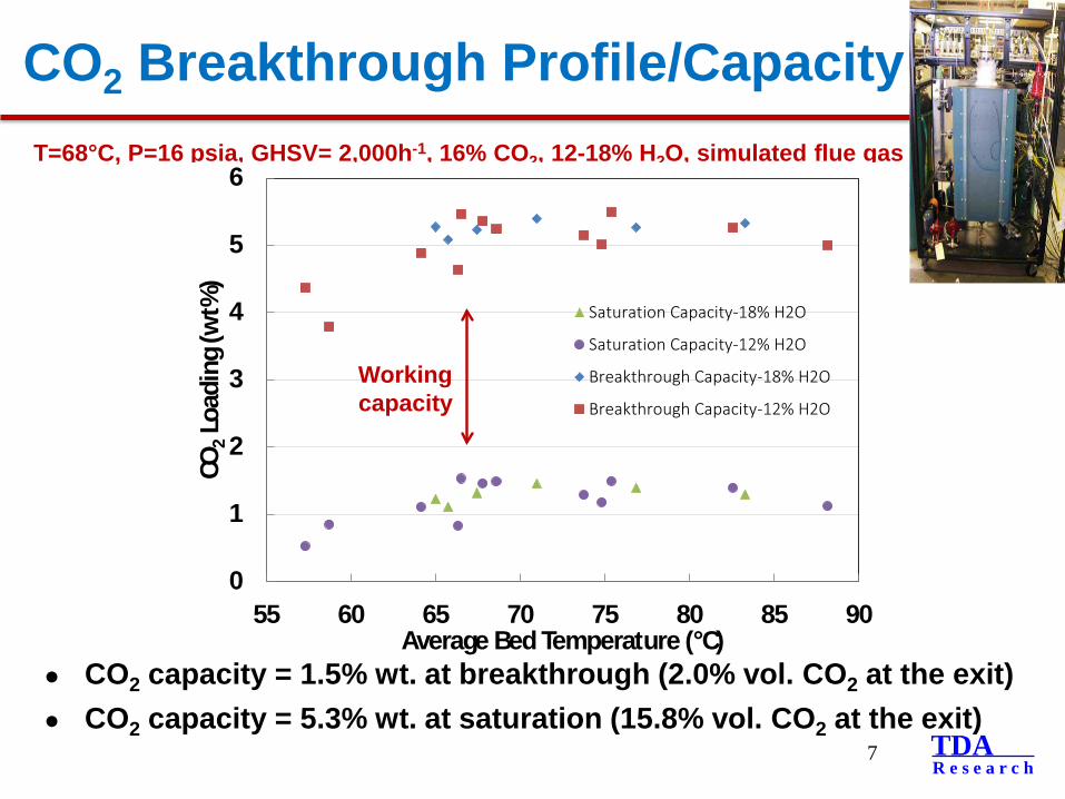
CO2 Breakthrough Profile/Capacity
7
CO2 capacity = 1.5% wt. at breakthrough (2.0% vol. CO2 at the exit) CO2 capacity = 5.3% wt. at saturation (15.8% vol. CO2 at the exit)
T=68°C, P=16 psia, GHSV= 2,000h-1, 16% CO2, 12-18% H2O, simulated flue gas
0
1
2
3
4
5
6
55 60 65 70 75 80 85 90
CO2
Load
ing (
wt%
)
Average Bed Temperature (°C)
Saturation Capacity-18% H2O
Saturation Capacity-12% H2O
Breakthrough Capacity-18% H2O
Breakthrough Capacity-12% H2O
Working capacity
TDAR e s e a r c h
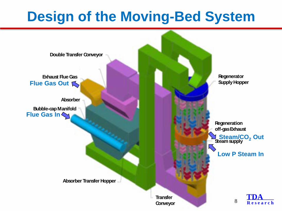
Bubble-cap Manifold
Exhaust Flue Gas
Absorber
Double Transfer Conveyor
Absorber Transfer Hopper
Transfer Conveyor
Steam supply
Regeneration off-gas Exhaust
Regenerator Supply Hopper
Design of the Moving-Bed System
8
Flue Gas Out
Flue Gas In
Low P Steam In
Steam/CO2 Out
TDAR e s e a r c h
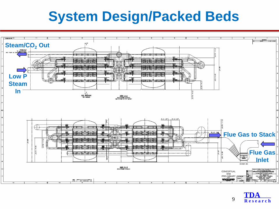
System Design/Packed Beds
9
Flue Gas Inlet
Low P Steam
In
Flue Gas to Stack
Steam/CO2 Out
TDAR e s e a r c h
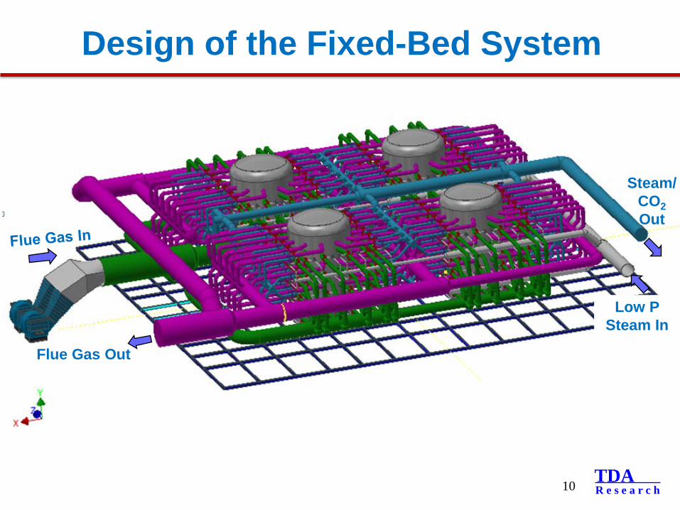
Design of the Fixed-Bed System
10
Flue Gas Out
Low P Steam In
Steam/CO2Out
TDAR e s e a r c h
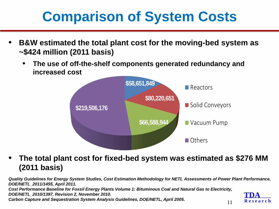
Comparison of System Costs• B&W estimated the total plant cost for the moving-bed system as
~$424 million (2011 basis)• The use of off-the-shelf components generated redundancy and
increased cost
• The total plant cost for fixed-bed system was estimated as $276 MM (2011 basis)
11
Quality Guidelines for Energy System Studies, Cost Estimation Methodology for NETL Assessments of Power Plant Performance, DOE/NETL_2011/1455, April 2011.Cost Performance Baseline for Fossil Energy Plants Volume 1: Bituminous Coal and Natural Gas to Electricity, DOE/NETL_2010/1397, Revision 2, November 2010.Carbon Capture and Sequestration System Analysis Guidelines, DOE/NETL, April 2005.
$58,651,849
$80,220,651
$66,588,944
$219,506,176
Reactors
Solid Conveyors
Vacuum Pump
Others
TDAR e s e a r c h
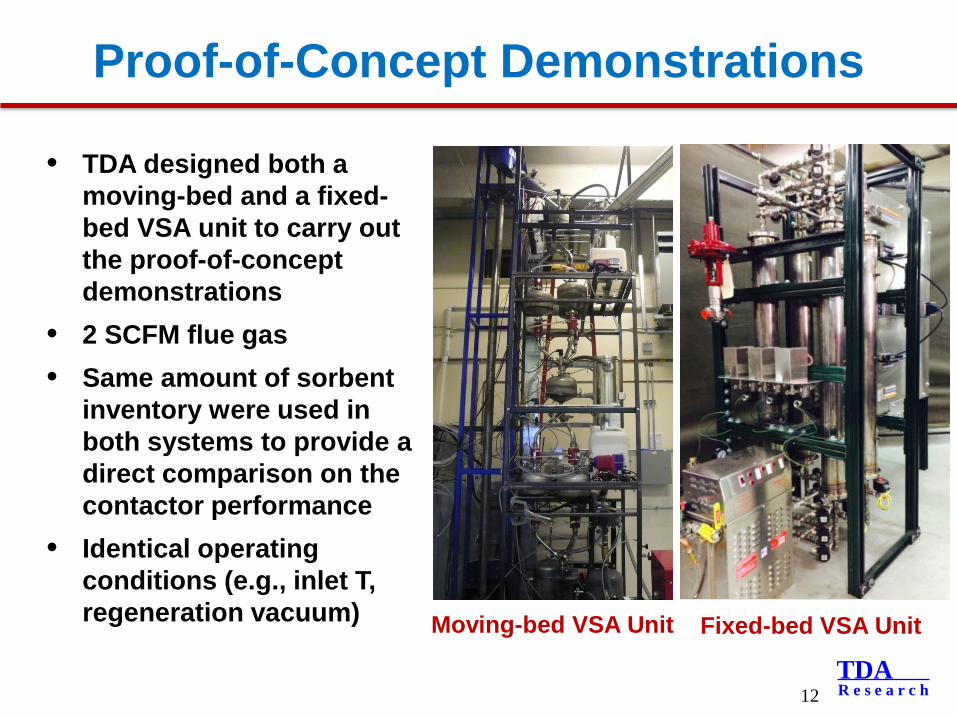
Proof-of-Concept Demonstrations
12
• TDA designed both a moving-bed and a fixed-bed VSA unit to carry out the proof-of-concept demonstrations
• 2 SCFM flue gas• Same amount of sorbent
inventory were used in both systems to provide a direct comparison on the contactor performance
• Identical operating conditions (e.g., inlet T, regeneration vacuum) Moving-bed VSA Unit Fixed-bed VSA Unit
TDAR e s e a r c h
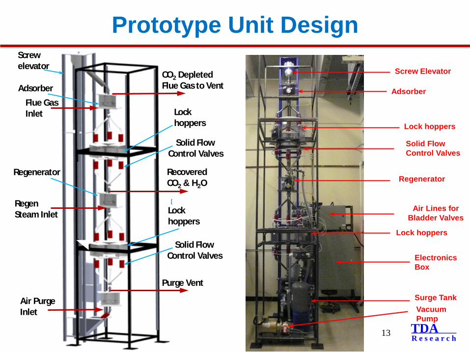
Prototype Unit Design
13
Electronics Box
Air Lines for Bladder Valves
Screw Elevator
Lock hoppers
Lock hoppers
Adsorber
Regenerator
Solid Flow Control Valves
Vacuum Pump
Surge Tank
AdsorberFlue Gas Inlet
CO2 Depleted Flue Gas to Vent
Lock hoppers
RegenSteam Inlet
Recovered CO2 & H2O
Air Purge Inlet
Regenerator
Screw elevator
Solid Flow Control Valves
Lock hoppers
Solid Flow Control Valves
Purge Vent
TDAR e s e a r c h
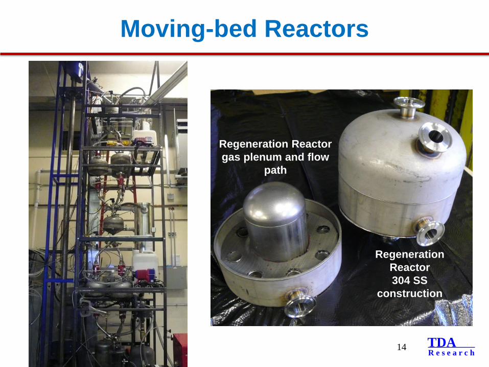
Regeneration Reactor304 SS
construction
Regeneration Reactor gas plenum and flow
path
Moving-bed Reactors
14
TDAR e s e a r c h
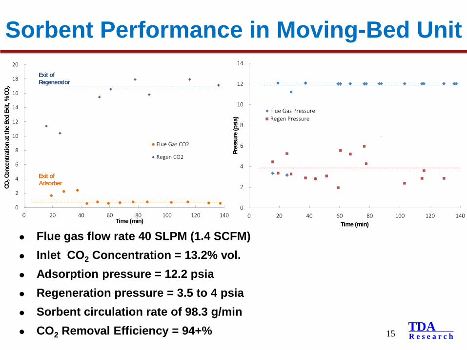
Sorbent Performance in Moving-Bed Unit
15
Flue gas flow rate 40 SLPM (1.4 SCFM) Inlet CO2 Concentration = 13.2% vol. Adsorption pressure = 12.2 psia Regeneration pressure = 3.5 to 4 psia Sorbent circulation rate of 98.3 g/min CO2 Removal Efficiency = 94+%
0
2
4
6
8
10
12
14
0 20 40 60 80 100 120 140
Pres
sure
(psia
)Time (min)
Flue Gas PressureRegen Pressure
0
2
4
6
8
10
12
14
16
18
20
0 20 40 60 80 100 120 140
CO2
Conc
entra
tion
at th
e Be
d Ex
it, %
CO 2
Time (min)
Flue Gas CO2
Regen CO2
Exit of Regenerator
Exit of Adsorber

TDAR e s e a r c h
Flue gas In
CO2 Out
Sorbentvessels 4 x 7L
Boiler
Valve manifoldProcess pumps
Steam valves
Condensors
G/ L separators
Flue gas Out
4-Bed VSA System
16
TDAR e s e a r c h
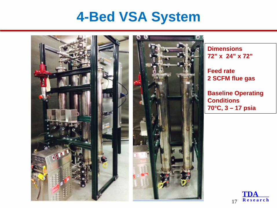
4-Bed VSA System
17
Dimensions72” x 24” x 72”
Feed rate2 SCFM flue gas
Baseline Operating Conditions 70°C, 3 – 17 psia
TDAR e s e a r c h
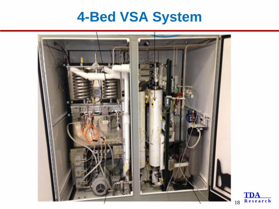
4-Bed VSA System
18
TDAR e s e a r c h
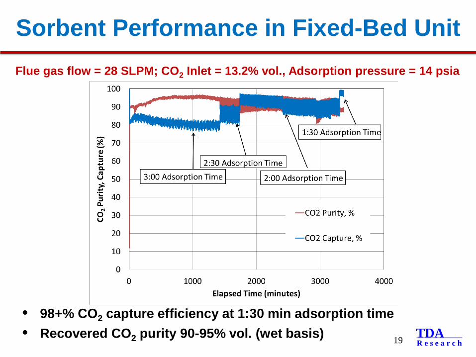
Sorbent Performance in Fixed-Bed Unit
19
Flue gas flow = 28 SLPM; CO2 Inlet = 13.2% vol., Adsorption pressure = 14 psia
• 98+% CO2 capture efficiency at 1:30 min adsorption time• Recovered CO2 purity 90-95% vol. (wet basis)
TDAR e s e a r c h
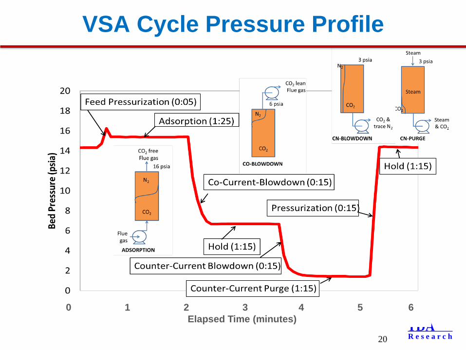
VSA Cycle Pressure Profile
20
0 1 2 3 4 5 6Elapsed Time (minutes)
TDAR e s e a r c h
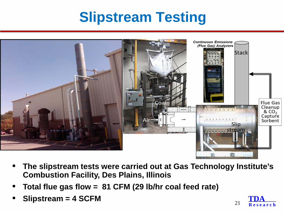
Slipstream Testing
21
• The slipstream tests were carried out at Gas Technology Institute’s Combustion Facility, Des Plains, Illinois
• Total flue gas flow = 81 CFM (29 lb/hr coal feed rate)• Slipstream = 4 SCFM
TDAR e s e a r c h
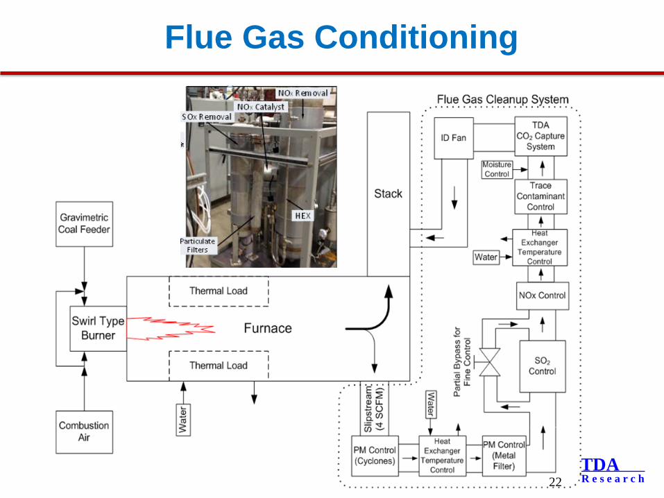
Flue Gas Conditioning
22
TDAR e s e a r c h
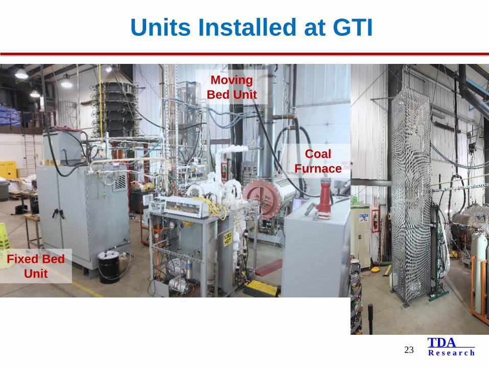
Units Installed at GTI
23
Fixed Bed Unit
Coal Furnace
Moving Bed Unit

TDAR e s e a r c h
Illinois #6 Coal Derived Flue Gas
24
4-bed VSA system removed 95+% CO2 in the flue gas and the CO2product purity was above 90%
Sorbent maintained stable performance in the presence of 370 ppmv NOx and 50 ppmv SOx
Flue gas composition: 13% vol. CO2, 370 ppm NOx, and 50 ppm SOx
Inlet Outlet
TDAR e s e a r c h
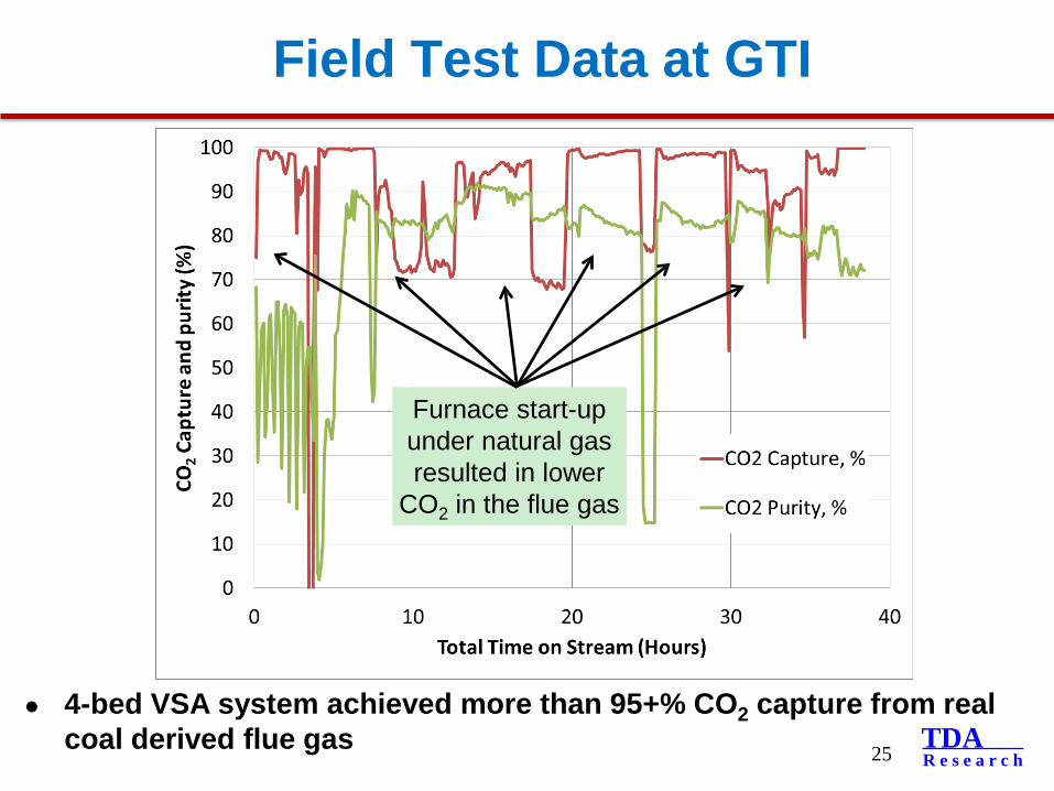
Field Test Data at GTI
25
4-bed VSA system achieved more than 95+% CO2 capture from real coal derived flue gas
Furnace start-up under natural gas resulted in lower
CO2 in the flue gas
TDAR e s e a r c h
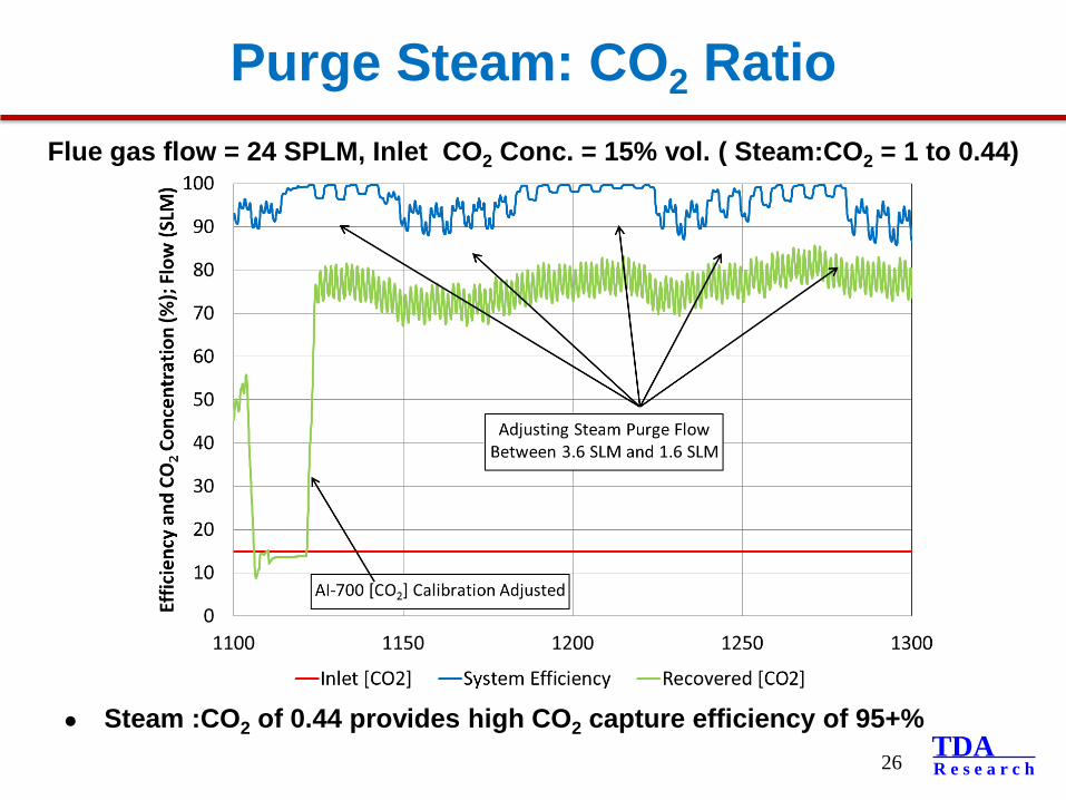
Purge Steam: CO2 Ratio
26
Steam :CO2 of 0.44 provides high CO2 capture efficiency of 95+%
Flue gas flow = 24 SPLM, Inlet CO2 Conc. = 15% vol. ( Steam:CO2 = 1 to 0.44)
TDAR e s e a r c h
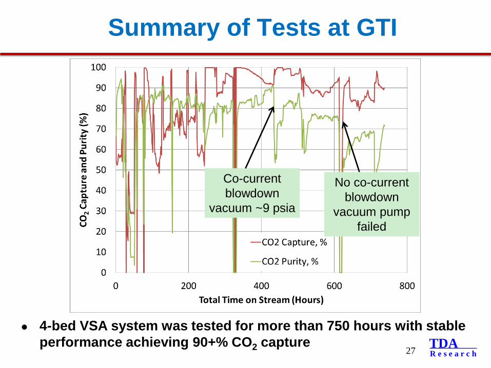
Summary of Tests at GTI
27
4-bed VSA system was tested for more than 750 hours with stable performance achieving 90+% CO2 capture
Co-current blowdown
vacuum ~9 psia
No co-current blowdown
vacuum pump failed
TDAR e s e a r c h
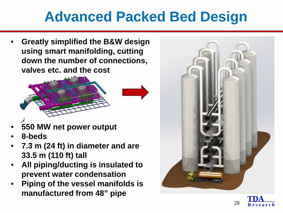
Advanced Packed Bed Design
28
• Greatly simplified the B&W design using smart manifolding, cutting down the number of connections, valves etc. and the cost
• 550 MW net power output• 8-beds• 7.3 m (24 ft) in diameter and are
33.5 m (110 ft) tall• All piping/ducting is insulated to
prevent water condensation• Piping of the vessel manifolds is
manufactured from 48” pipe
TDAR e s e a r c h
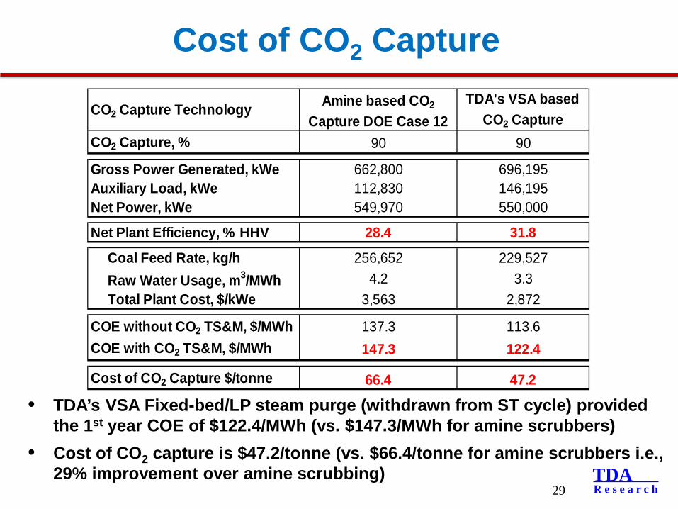
Cost of CO2 Capture
• TDA’s VSA Fixed-bed/LP steam purge (withdrawn from ST cycle) provided the 1st year COE of $122.4/MWh (vs. $147.3/MWh for amine scrubbers)
• Cost of CO2 capture is $47.2/tonne (vs. $66.4/tonne for amine scrubbers i.e., 29% improvement over amine scrubbing)
29
CO2 Capture Technology Amine based CO2
Capture DOE Case 12TDA's VSA based
CO2 CaptureCO2 Capture, % 90 90
Gross Power Generated, kWe 662,800 696,195Auxiliary Load, kWe 112,830 146,195Net Power, kWe 549,970 550,000
Net Plant Efficiency, % HHV 28.4 31.8
Coal Feed Rate, kg/h 256,652 229,527 Raw Water Usage, m3/MWh 4.2 3.3 Total Plant Cost, $/kWe 3,563 2,872
COE without CO2 TS&M, $/MWh 137.3 113.6COE with CO2 TS&M, $/MWh 147.3 122.4
Cost of CO2 Capture $/tonne 66.4 47.2
TDAR e s e a r c h
Acknowledgements
30
• The funding from DOE/NETL under Contract No. DE-FE-0007580 is greatly acknowledged
• Technical Monitor, Andrew O’Palko, NETL• Dr. Chuck Shistla and Andy Hill, GTI• Dr. Bartev Sakadjian, Doug Devault, Ruyu Zhang, B&W• Dr. Ashok Rao, UCI• Dr. Francois Botha and Dr. Debalina Dasgupta, ICCI