Positions Held - Seoul National University
53
Transcript of Positions Held - Seoul National University

1
Positions Held: • April 2014– till date: Deputy General Manager, Samsung C&T, Water & Envorinment • January 2012– April 2014: Engineering Director Veolia Argentina • June 2007- September 2012: Applications Director Veolia Argentina • July 2005-June 2007: Process & Design Engineer Degrémont Argentina • May 2003-July 2005: Process Engineer and Engineering Manager Degrémont Korea • May 2002-May 2003: Design Engineer Degrémont Chili (off shore office Degrémont France) • May 1997-May 2002: Process Engineer, Project Manager, Star Up Engineer and Design
Engineer Degrémont Argentina
Experience:
3 years in water analysis laboratory and 17 years involved in different water treatment projects acting with several roles as Project Manager, Design Engineer and Process Engineer
2
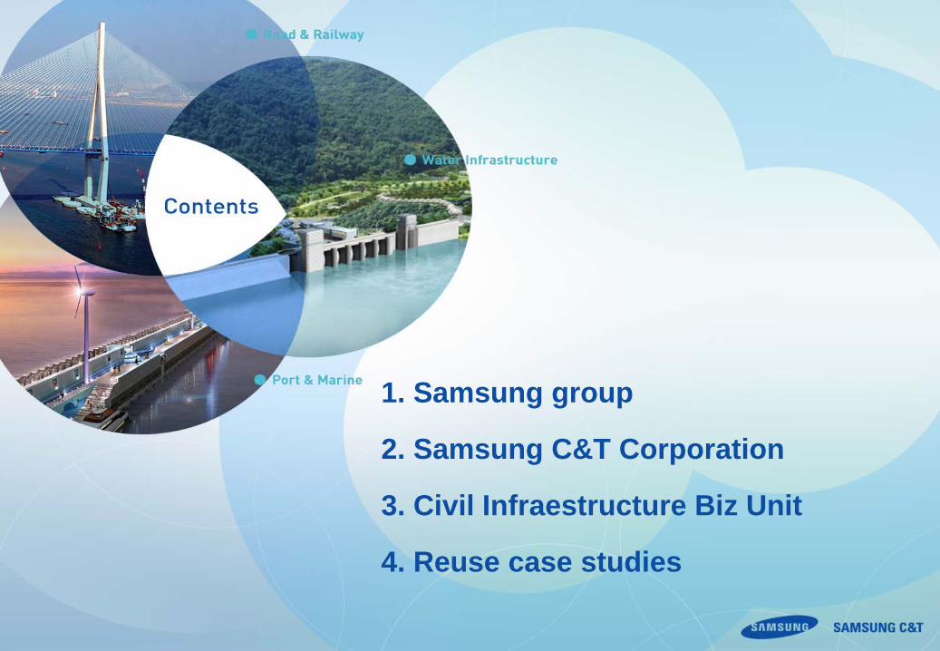
1. Samsung group
2. Samsung C&T Corporation
3. Civil Infraestructure Biz Unit
4. Reuse case studies

3
1. Samsung Group

4
Samsung C&T Corporation Samsung Engineering Samsung Heavy Industries
Samsung Electronics Samsung Electro-Mechanics Samsung SDI Samsung SDS Samsung Display Samsung Corning Advanced Glass
Cheil Industries Samsung Everland The Shilla Hotels & Resorts Cheil Worldwide S1 Corporation Samsung Medical Center Samsung Economics Research Institute Samsung Bioepis Samsung Biologics Samsung Welstory
Samsung Life Insurance Samsung Fire & Marine Insurance Samsung Card Samsung Securities Samsung Investment Trust Management Samsung Venture Investment
Samsung Total Petrochemicals Samsung Petrochemicals Samsung Fine Chemicals Samsung BP Chemicals Samsung Techwin

5
2. Samsung C&T Corporation

6
Road, Bridge & Tunnel Metro & Railway Port & Marine Water Resources Mining
Power Generation Nuclear Power Plant Energy Storage Industrial Plant
High-Rise, Mixed-Use Hi-Tech Healthcare, Aviation Sports Facilities
Residential Complex Urban Development
Global Marketing Procurement
R&D Center
Q-HSE Corporate Support Human
Resources Strategy
& Innovation Finance
& Accounting Risk
Management
Chief Executive Officer Mr. Chi-Hun Choi
Civil Infra. M&E Building/Housing M&E Industrial Facility M&E

7
10,665 Manpower HQ: 3,173 / Global Offices: 406 / Sites: 7,086
36 Global Offices in 26 Countries Regional HQ: 3 / Local Subsidiary: 15 / Branch: 18
(HQ)
(Southeast Asia RHQ)
(Middle East RHQ)

8
3. Civil Infrastructure Business Unit

9
− Dam / Hydropower Plant − Water & Wastewater Treatment − Sewer & Water Tunnel − Soil Remediation
− High Speed Railway − LRT / MRT − Freight − Mining Infrastructure
− Bridge & Tunnel − Highway & Roadway − Underground Expressway
Total solution provider in all areas of the construction business – financing, planning, design, procurement, construction, and O&M
Metro &
Railway
Road &
Bridge
Port &
Marine
Water &
Environment
F/S F/S F/S F/S F/S EPC Financing O&M
− Wharf / Breakwater / Jetty − Dock / Dredging / Reclamation − Offshore (Wind Farm, Pipeline) − Mining Infrastructure
10
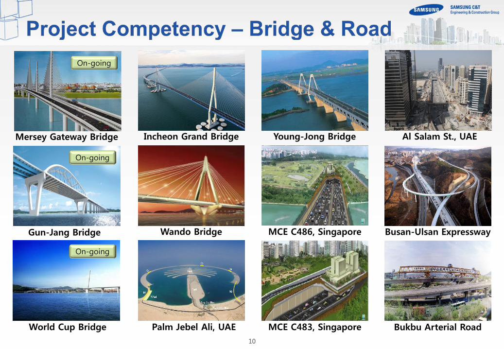
Incheon Grand Bridge Young-Jong Bridge
Wando Bridge Gun-Jang Bridge
Palm Jebel Ali, UAE World Cup Bridge
Busan-Ulsan Expressway MCE C486, Singapore
Bukbu Arterial Road
Al Salam St., UAE
MCE C483, Singapore
Mersey Gateway Bridge
On-going
On-going
On-going
11
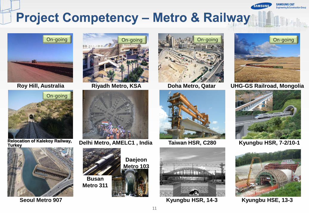
Riyadh Metro, KSA
Daejeon Metro 103
Doha Metro, Qatar
Seoul Metro 907
Delhi Metro, AMELC1 , India
Busan Metro 311
UHG-GS Railroad, Mongolia
Taiwan HSR, C280
Kyungbu HSR, 14-3 Kyungbu HSE, 13-3
Kyungbu HSR, 7-2/10-1
On-going On-going On-going
Roy Hill, Australia
On-going
On-going
Relocation of Kalekoy Railway, Turkey

12
Busan New Port Incheon South Port Ulsan North Breakwater
Jeju Naval Base(Caisson)
Ulsan New Port (Caisson)
Wastewater Treat, Thailand
Dookdo Purification Facility
Yong-dam Multi Dam Kyung-in Ara Canal DTSS T-04, Singapore
DTS T01, UAE
On-going On-going On-going On-going
Son Duong Port, Vietnam

13
4. Waste to Energy
14
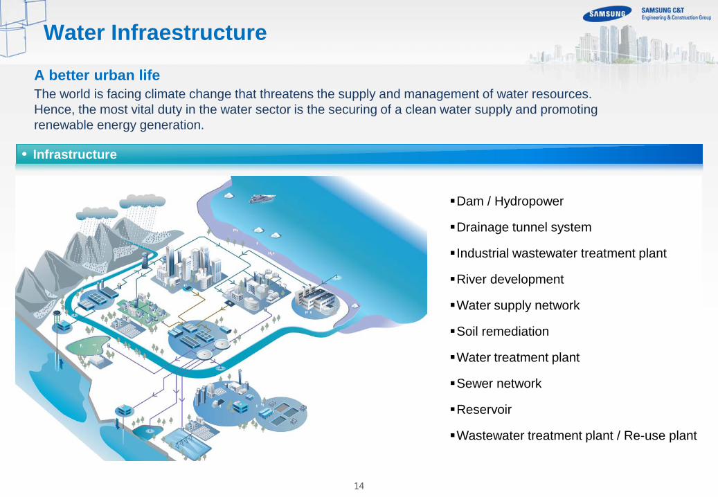
A better urban life The world is facing climate change that threatens the supply and management of water resources. Hence, the most vital duty in the water sector is the securing of a clean water supply and promoting renewable energy generation.
Infrastructure
Dam / Hydropower
Drainage tunnel system
Industrial wastewater treatment plant
River development
Water supply network
Soil remediation
Water treatment plant
Sewer network
Reservoir
Wastewater treatment plant / Re-use plant
Water Infraestructure

15
1. Minimize process energy consumption i. High efficiency equipment ii. Diffusers iii. Blowers
2. Process control i. PLC and Scada ii. Control optimization
3. Process improvement i. Cutting edge technologies ii. Optimal efficiency with lower energy
consumption iii. Optimal sludge generation and
handling scheme
Savings in treatment
Waste 2 Energy
Savings in treatment
Generating energy
By products
Reuse
Waste to Energy-Savings in treatment

16
Fluid bed incineration Thermal processes used in sludge disposal have become more attractive as process improvements have been introduced, such as power generation and efficient heat recovery. Sustainable management is the main driver. Fluid bed furnaces, especially the hot windbox (HWB) fluid bed, could operate without the use of any auxiliary fuel. The reduction in fossil fuel consumption as well as the ability to produce electrical energy from a renewable source not only offsets the net carbon footprint of the treatment facility but can also qualify for carbon credits if and when such provisions are available for this treatment district.
Savings in treatment-High efficiency equipments
17
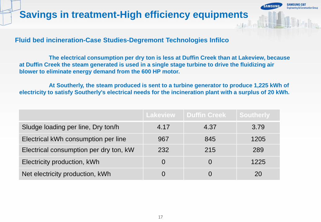
The electrical consumption per dry ton is less at Duffin Creek than at Lakeview, because at Duffin Creek the steam generated is used in a single stage turbine to drive the fluidizing air blower to eliminate energy demand from the 600 HP motor. At Southerly, the steam produced is sent to a turbine generator to produce 1,225 kWh of electricity to satisfy Southerly’s electrical needs for the incineration plant with a surplus of 20 kWh.
Lakeview Duffin Creek Southerly
Sludge loading per line, Dry ton/h 4.17 4.37 3.79
Electrical kWh consumption per line 967 845 1205 Electrical consumption per dry ton, kW 232 215 289
Electricity production, kWh 0 0 1225
Net electricity production, kWh 0 0 20
Fluid bed incineration-Case Studies-Degremont Technologies Infilco
Savings in treatment-High efficiency equipments

18
Organica FCR Reactor Is The “Heart of the Solution” Plants on the supporting mesh
Fine bubble aeration
Activated sludge in suspension
Engineered supporting media
Root zone (up to 1.5m) as fixed film carrier
Walkway and plant supporting rack
3-5 kg of biomass /m3
800 species
18
12-18 kg of biomass /m3
Savings in treatment-Process improvements

19 19 19
Series Of Food Chain Reactor Zones
• The biological process takes place in a series of cascade reactors, with standard pretreatment at the beginning, and phase separation (via Organica Disc Filters or Secondary Clarifiers) and final polishing at the end.
• As water flows through from one reactor zone to the next, different ecologies will grow and adapt to the conditions in each stage. This configuration allows the “food chain effect” to develop, as higher level organisms become predators for the simpler organisms.
• The result is enhanced removal efficiency and resiliency, while utilizing less energy and producing less sludge.
Savings in treatment-Process improvements

20 20
Savings in treatment-Process improvements
Organica’s Food-Chain-Reactor (FCR) is a complete wastewater treatment solution incorporated into a compact, single structure. Plants are selected for their root structure, root mass and their ability to withstand the conditions in various reactors. Only locally available species are used, plants are never transported across borders. Plant maintenance comprises of simple gardening practices that can be performed by ordinary wastewater plant operators, no special skills are required.
Microbial fuel cell

22
Needs : Sludge volume Reduction & Producing energy from sludge Solution: Anaerobic digestion enhanced by TH (Thermal Hydrolysis) High temperature (165°C), pressure (10 bar) and retention time (>30’) allows to ”crack” long chain molecules
Effects : Solubilisation of organic matter previously not accessible for digestion Pathogen destruction Disintegrates cell structure/organic materials and dissolves naturally occurring cell polymers (exopolymeric substances- EPS), a form of protein, into an easily digestible feed for anaerobic digestion
Generating Energy-Optimum biogas generation

23 23
1) Improving sludge biodegradability by THP 150-165°C and 6-9 bar 20-30min on concentrated sludge > 16% dryness batch or continuous
2) Treating the hydrolyzed sludge by MAD,
producing more biogas and reducing DS 15 days HRT 37-41°C
Principle THP + MAD (Mesophilic Anaerobic Digestion) Exelys Biothelys® Veolia
Digestion – Lysis – Digestion
Generating Energy-Optimum biogas generation

24 24
Advantages of thermal hydrolysis Provide higher VM removal and higher biogas production Hygienisation (EPA class A) Dewatering (better dryness)
Biological sludge: from 21-22% to 28-35% by centrifuge High final digested sludge volume reduction
sludge viscosity Improvement (digester can operate at higher concentration) Volume of digester following TH reduced by 2-3 High sludge quality: odorless, easy storage No foaming in digester observed
Biogas production increase (+30%) Sludge to disposal decrease (-35%)
OR The capacity of the Digester increase (up to 50%)
AND Complete hygiénisation of sludge
And efficient, reliable and robust solution
Generating Energy-Optimum biogas generation

25 25
TMAD 920 m3
63% VM rem
CHP: 347 kWe 3723 Nm3/d
160 t/d 10tDS/d 25°C
MAD 2400 m3
MAD 4000 m3
50% VM rem
160 t/d 10tDS/d 25°C
2927 Nm3/d CHP: 273kWe
25t/d, 25%
12,5t/d, 34%
Conventional
DLD
Generating Energy-Optimum biogas generation
26
Generating Energy-Generating biogas
27
Generating Energy-Generating biogas

28
Are bioreactors that can convert the chemical energy present in organic compounds into chemical energy. Producing electricity using microrganism was first reported by Potter in 1911. MFCs are devices that produce energy by the biodegreation of organic matter using bacteria as catalysts. Consist of anodic and cathodic chambers separated by a proton exchange membrane (PEM). The oxidation of organic matter occurs in the anodic chamber through bacteria thet generate electron and protons. The electrons are aborbed by anode and transported to the cathode through an external circuit. Protons cross the PEM and enter the cathodic chamber where they combine with oxygen to form water. There are several electrochemically active bacteria which have the capability to transfer electrons from inside the cell to the extracellular acceptors through c-type cytochromes and microbial nanowires (flagella) present on their outer membrane
Microbial fuel cell
Generating Energy-Biological fuel cell

29
MFCs play the dual duty of degrading effluents and generating power by the treatment of industrial and municipal wastewater. There is a linear relationship between the organic content of wastewater and the power output of MFCs. The biological oxygen demand (BOD) is an indication of the strength of wastewater, and the power output of an MFC reflects the BOD of the wastewater, making MFC a possible BOD sensor. Therefore, MFCs can be used to reduce the COD of wastewater and simultaneously generate power. fed with primary sludge the MFC reduced both organic and suspended solids, but the energy output was lower and the formation of methane gas dominated the total energy Production.This led to the opinion that although it may be challenging to use MFCs consuming primary sludge for energy production, it may find use in polishing the digested effluent from anaerobic digesters. Also MFCs can be turned into a microbial electrolysis cell (MEC) by adding a small suplement electricity at the cathode to produce products such as hydrogen gas.
Microbial fuel cell
Generating Energy-Biological fuel cell

30
The BEAMR and MFC systems share many similar characteristics, and therefore many findings for improving electricity generation in MFCs should be applicable for increasing hydrogen production in the BEAMR system. Hydrogen production was examined using domestic wastewater as the fuel in the BEAMR process, and Evaluated system performance in terms of hydrogen recovery, CE, and the effectiveness of treatment (BOD, COD, and DOC removal). The initial condition ranges for the wastewater were: BOD, 86 to 270 mg/L; COD, 204 to 481 mg/L; DOC, 56.8 to 90 mg/L. The average BOD concentration (BOD5) at the end of a batch cycle was 4.5 mg/L with a maximum of 7.0 mg/L and was not a function of the initial wastewater strength. Overall removals (graphite granule tests) were: BOD, 97 %; COD, 95;and DOC, 92. It is reasonable to expect that domestic wastewater could be used to make hydrogen in the BEAMR process as either acetate or wastewater can be used to generate electricity in an MFC.
Bio-electrochemically assisted microbial reactor
Generating Energy-Biological fuel cell
31
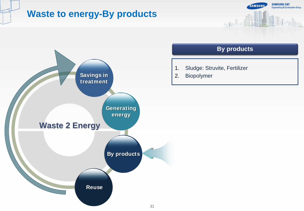
1. Sludge: Struvite, Fertilizer 2. Biopolymer
By products
Waste 2 Energy
Savings in treatment
Generating energy
By products
Reuse
Waste to energy-By products

32
PHA
By products-Biopolymer
Alcaligenes latus loaded with PHA granules
Polyhydroxyalkanoates (PHAs) are thermoplastic polymers that are biodegradable and can be produced from renewable resources. The main subtrates used for the selective growth of PHA storing organism and PHA production have been volatile fatty acids (VFAs) since VFAs are efficiently converted into PHAs, whereas carbohydrates are preferably stored as polysaccharides. For every ten tonnes of COD removed in a biological wastewater treatment system one to four tonnes of biomass is produced, in which contains bacteria that can store PHA

33
By products-Biopolymer
34
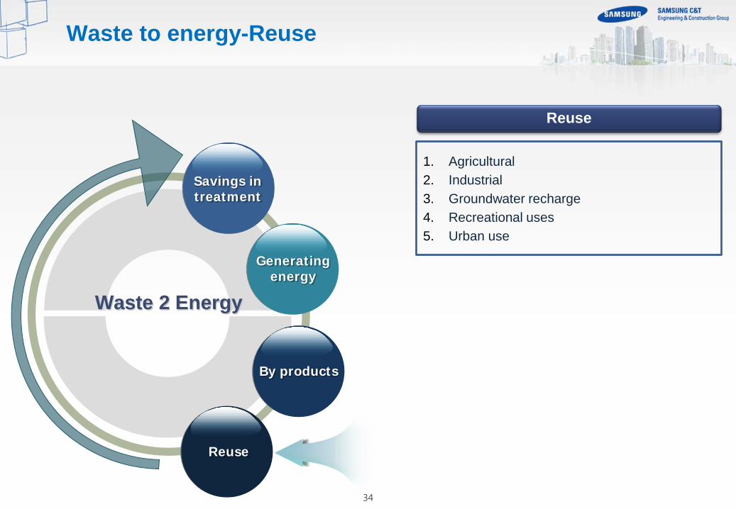
1. Agricultural 2. Industrial 3. Groundwater recharge 4. Recreational uses 5. Urban use
Reuse
Waste 2 Energy
Savings in treatment
Generating energy
By products
Reuse
Waste to energy-Reuse

35
Energy efficiency and sustainability are key drivers of water reuse, which is why water reuse is so integral to sustainable water management. The water-energy nexus recognizes that water and energy are mutually dependent, energy production requires large volumes of water, and water infrastructure requires large amounts of energy. Sustainable development is development that meets the needs of the present without compromising the ability of future generations to meet their own needs, therefore, sustainable water management can be defined as water resource management that meets the needs of present and future generations. Water reuse is integral to sustainable water management because it allows water to remain in the environment and be preserved for future uses while meeting the water requirements of the present. Water and energy are interconnected, and sustainable management of either resource requires consideration of the other. Water reuse reduces energy use by eliminating additional potable water treatment and associated water conveyance because reclaimed water typically offsets potable water use and is used locally.
Reuse- Description

36
De facto reuse: A situation where reuse of treated wastewater is, in fact, practiced but is not officially recognized (e.g., a drinking water supply intake located downstream from a wastewater treatment plant [WWTP] discharge point). Direct potable reuse (DPR): The introduction of reclaimed water (with or without retention in an engineered storage buffer) directly into a drinking water treatment plant, either collocated or remote from the advanced wastewater treatment system. Indirect potable reuse (IPR): Augmentation of a drinking water source (surface or groundwater) with reclaimed water followed by an environmental buffer that precedes drinking water treatment. Nonpotable reuse: All water reuse applications that do not involve potable reuse. Potable reuse: Planned augmentation of a drinking water supply with reclaimed water.
Reuse-Definitions

37
The cities face weakness in the traditional practices of water management, which typically focus on individual resources or utilities. Dry weather stormwater represents low flows that occur during non-peak events that may end up in the wastewater collection system, and wet weather stormwater represents higher flow periods that generally end up as discharge to receiving waters. Urban watersheds use more receiving waters for their water supplies and wastewater and stormwater into receiving waters. Reduce the demand for freshwater are part of this comprehensive management Approach, like rather than viewing stormwater as a nuisance, it should be considered an asset that is allowed to recharge groundwater through best management practices, such as the use of swales, porous pavement, or cisterns. Additionally, wastewater can be reused, providing both environmental and water supply benefits
Water Management
Reuse & Management
38
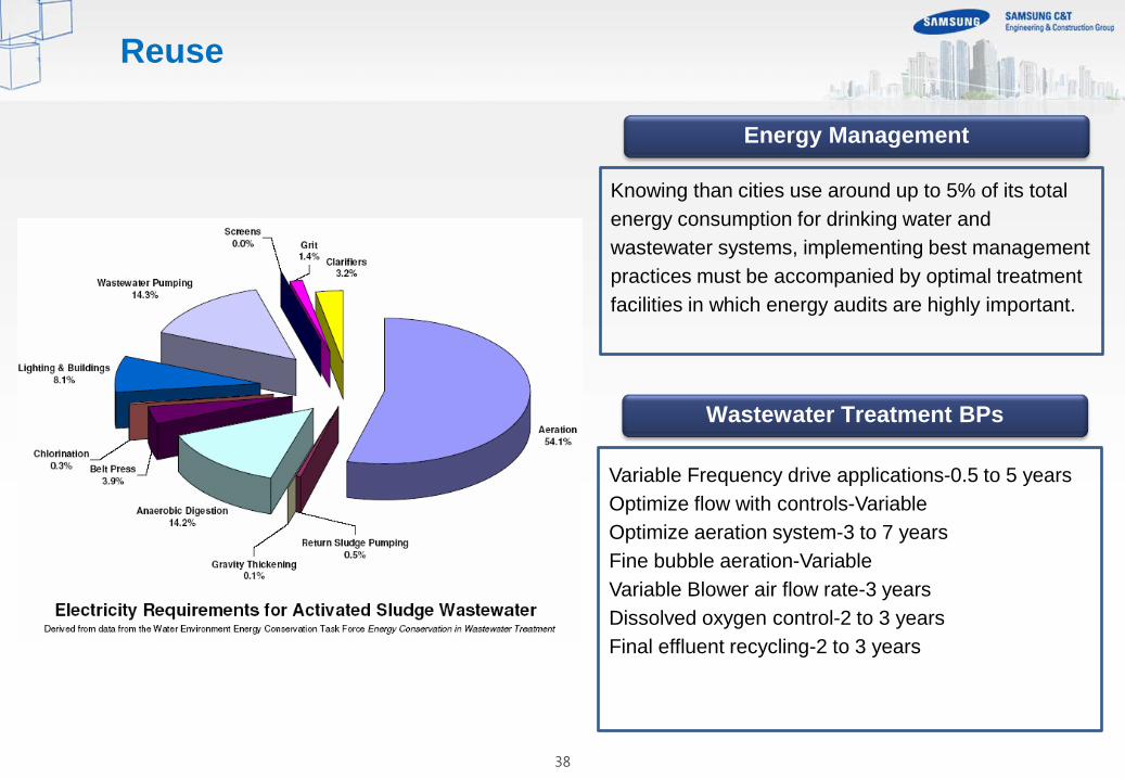
Knowing than cities use around up to 5% of its total energy consumption for drinking water and wastewater systems, implementing best management practices must be accompanied by optimal treatment facilities in which energy audits are highly important.
Energy Management
Variable Frequency drive applications-0.5 to 5 years Optimize flow with controls-Variable Optimize aeration system-3 to 7 years Fine bubble aeration-Variable Variable Blower air flow rate-3 years Dissolved oxygen control-2 to 3 years Final effluent recycling-2 to 3 years
Wastewater Treatment BPs
Reuse

39
Water & Energy Management
Reuse & Applications

40
Treated wastewater can achieved the values shown in this chart and with the a proper local wastewater management energy consumption and water footprint can be optimized.
Wastewater Reuse
Primary Secondary Tertiary
BOD 19% 74% 5%
TSS 40% 55% 4%
TOC 21% 64% 8%
Ammonia-N 5% 52% 1%
Phosphate-P 16% 28% 54%
Iron 11% 59% 22%
Reuse & Applications and quality
41
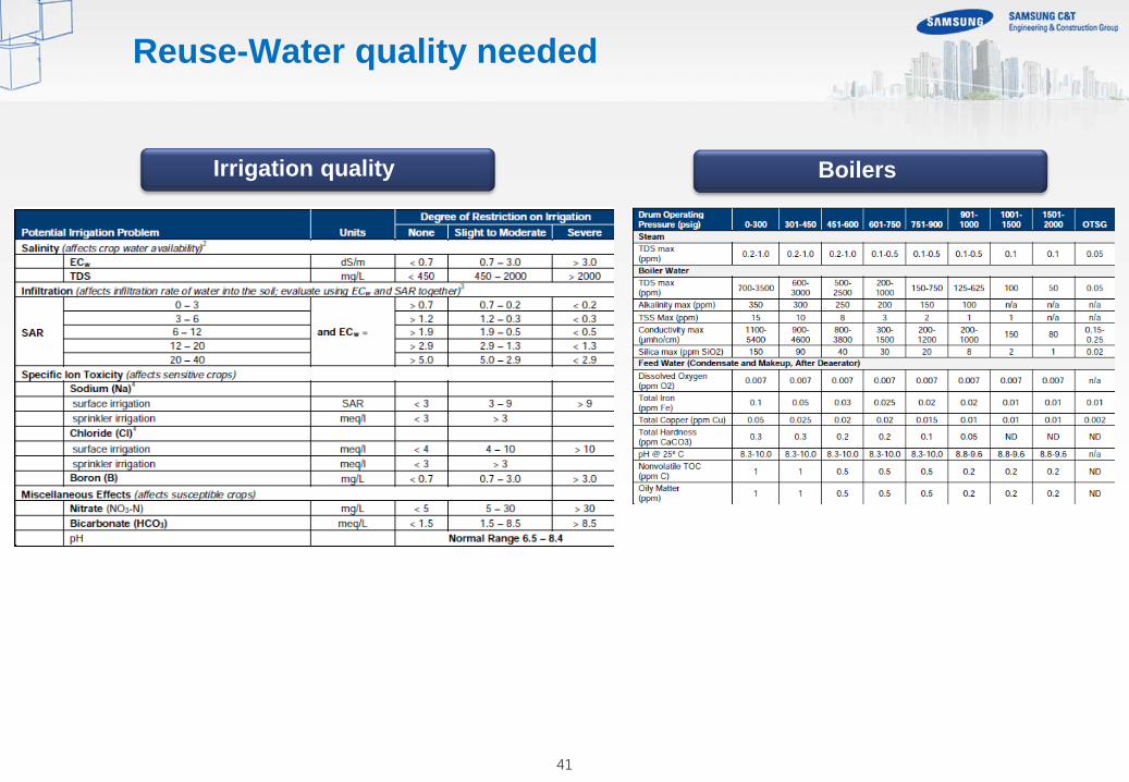
Reuse-Water quality needed
Boilers Irrigation quality
42
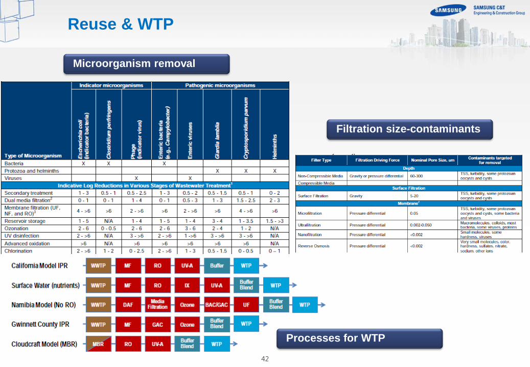
Reuse & WTP
Microorganism removal
Filtration size-contaminants
Processes for WTP

43
4. Reuse case studies

44
The State of São Paulo is the world’s seventh most populous urban area. The region contains nearly one-fourth of the country’s population but less than 2% of Brazil’s water. The state government, recognizing the importance of safeguarding drinking water for the region’s inhabitant, issued regulations to restrict the industrial use of potable water, forcing factories to look for ways to reuse their wastewater, or obtain recycled water from another source. Upon completion, this groundbreaking facility will free up enough drinking water to continuously supply a population of 350,000 inhabitants, with the potential capacity to reach 600,000.
Description Koch Membrane Systems (KMS) concluded that membrane bioreactor (MBR) technology with a Tertiary Membrane Bioreactor (TMBR) system was the best solution for the new facility. The Aquapolo facility employees KMS’PURON® MBR technology as well as MegaMagnum® reverse osmosis (RO) membranes. The initial 2012/2014 phase will produce 56,160 m3/ day (650 L/s) of reuse water, eventually reaching a capacity of 86,400 m3/day.
Solution
Reuse-Case study-Aquapolo-Industry
45
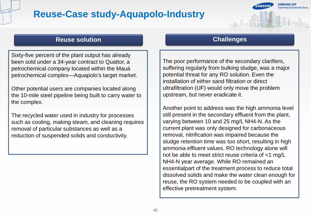
Sixty-five percent of the plant output has already been sold under a 34-year contract to Quattor, a petrochemical company located within the Mauá petrochemical complex—Aquapolo’s target market. Other potential users are companies located along the 10-mile steel pipeline being built to carry water to the complex. The recycled water used in industry for processes such as cooling, making steam, and cleaning requires removal of particular substances as well as a reduction of suspended solids and conductivity.
Reuse solution
The poor performance of the secondary clarifiers, suffering regularly from bulking sludge, was a major potential threat for any RO solution. Even the installation of either sand filtration or direct ultrafiltration (UF) would only move the problem upstream, but never eradicate it. Another point to address was the high ammonia level still present in the secondary effluent from the plant, varying between 10 and 25 mg/L NH4-N. As the current plant was only designed for carbonaceous removal, nitrification was impaired because the sludge retention time was too short, resulting in high ammonia effluent values. RO technology alone will not be able to meet strict reuse criteria of <1 mg/L NH4-N year average. While RO remained an essentialpart of the treatment process to reduce total dissolved solids and make the water clean enough for reuse, the RO system needed to be coupled with an effective pretreatment system.
Challenges
Reuse-Case study-Aquapolo-Industry

46
Process-PFD
Primary
Pre treatment Disc Filter 400 micra
Bio recators 3500 m3
Membrane cassettes 63 units/1500 m2 each/94.500 m2
Flux 25 l/m2.h
MLSS (Membrane tanks) 5 to 8 g/l
MLSS (bio recators) 6.4 g/l
Reuse-Case study-Aquapolo-Industry

47
Results
Reuse-Case study-Aquapolo-Industry

48
Recover municipal wastewater from Kuwait City and the surrounding area. The consortium was established to design, build, own, operate and maintain a100 million gallon per day (mgd) (375,000 m3/day) wastewater treatment facility at Sulaibiya Near Kuwait City. The Sulaibiya facility is the world’s largest membrane-based water reclamation facility. The reclaimed and desalinated water from the Sulaibiya facility is used for non-potable uses that impact the drinking water supply, by blending with brackish water to better exploit existing brackish water distribution facilities
Description A conventional biological wastewater treatment plant (WWTP) treats the effluent to better than secondary effluent quality. The secondary effluent then flows to the water reclamation plant, which uses ultrafiltration (UF) and reverse osmosis (RO) to further treat the water for reuse. Sludge from the wastewater treatment plant is treated to allow for disposal by landfill, incineration, or by composting. The water reclamation plant is designed to treat 100 mgd (375,000 m3/day) of secondary effluent, which is prefiltered with disk filters and then fed to the ultrafiltration system. UF product feeds a reverse osmosis plant, and UF waste is recycled to the WWTP. The UF system treats 100% ofthe flow after biological treatment since the UF waste is recycled. Hence, the feed to the RO system is also 100 mgd. The RO plant is designed for 85% water recovery, so the expected production rate is 85 mgd.
Solution
Reuse-Case study-Kuwait city-Agriculture

49
The plant influent is typical domestic sewage. The WWTP is designed to produce an effluent with an average monthly value of less than 20 mg/l BOD and 20 mg/l TSS. The average total dissolved solids (TDS) in the feed Is 1,280 mg/l, and the plant product is less than 100 mg/l, significantly better than World Health Organization (WHO) potable water guidelines.
Results
The effluent fed to the UF first passes through a disk filter, after which a small amount of coagulant is added to coagulate fine particulates and possibly allow some TOC removal to facilitate the operation of the plant. The SDI of the UF product will be below 2, an important criterion for the RO plant performance. Previous experience treating secondary municipal effluent with UF has shown that SDI values of less than 1 are possible. The salinity of the municipal effluent has an average monthly value of 1,280 mg/l TDS, with a maximum value of 3,014 mg/l. RO is used to desalinate the water to 100 mg/l TDS, as well as provide a second barrier to bacteria and viruses. RO technology is well proven for desalinating municipal effluent. The system consists of 42 identical skids in a 4:2:1 array. Approximately 21,000 membranes, provided by Toray of America, were required for this project. The RO system is limited to operating at 85% recovery by calcium phosphate precipitation, which can frequently be the limiting factor for water recovery in membrane systems desalinating municipal effluent.
Process
Reuse-Case study-Kuwait city-Agriculture

50
The Wynnum Advanced Wastewater treatment plant is located south of the Brisbane River junction to the sea in Moreton Bay. Abundant wildlife live in and around Moreton Bay, which is like a lagoon because a series of off-shore barrier islands restrict the flow of oceanic water. In 2008, as part of the area’s sustainability efforts, an advanced wastewater treatment plant was built to produce Class A+ recycled water for industrial processes.
Description
The water reclamation plant receives feed water from the upgraded wastewater treatment plant. Table 1 details the average feed water quality.The effluent water is chloraminated (2-3 mg/L) (Cl2) and then directed to the balance tank, where it goes through 0.5 μm Amiad screens and two microfiltration units—the SDI of the MF filtrate is less than three 100% of the time. The pH is corrected with H2SO4, and then the water moves through MF filtrate tanks, and an antiscalant dose before being fed to RO units. The RO system consists of two identical units of 16:8 configurations and each pressure vessel houses seven elements 336 pieces of BW30-400/34i-FR membranes are installed. The units recover 75% with a total design capacity of 5.3 ML/d. From there, the RO permeate is sent to the degassing tower, breakpoint chlorinated and then stored. Produces 4,500 m3/d of high industrial grade Class A+ recycled water daily from municipal sewage.
Solution
Reuse-Case study-Australia-Industry
51
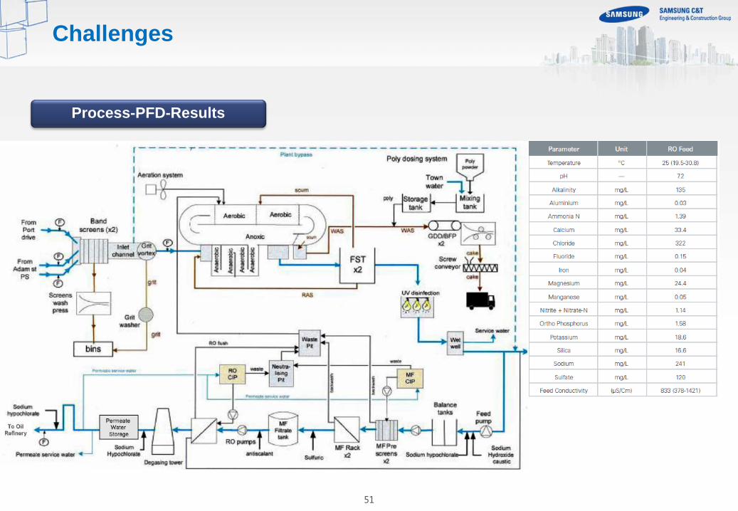
Process-PFD-Results
Challenges

52
Biosphere
Energy
Water Food
“Water is the driving force of all nature”
Energy is used for storing, cleaning and
transporting water
Water is needed for energy production
Energy can be produced from food crops
Food production uses a lot of energy
Water is needed for food production
Food production affects water availability

53