Portland Cements. In - Federal Highway Administration · Types IA, IIA, and IIIA have similar...
67
Welcome to the Highway Materials Engineering Course Module G, Lesson 2: Portland Cements. In this lesson, we will discuss the physical and chemical properties of Portland cement. A printer‐friendly version of the lesson materials can be downloaded by selecting the paperclip icon. Only the screens for the this lesson are available. If you need technical assistance during the training, please select the Help link in the upper right‐hand corner of the screen.
Transcript of Portland Cements. In - Federal Highway Administration · Types IA, IIA, and IIIA have similar...
Welcome to the Highway Materials Engineering Course Module G, Lesson 2: Portland Cements. In this lesson, we will discuss the physical and chemical properties of Portland cement.
A printer‐friendly version of the lesson materials can be downloaded by selecting the paperclip icon. Only the screens for the this lesson are available.
If you need technical assistance during the training, please select the Help link in the upper right‐hand corner of the screen.

By the end of this lesson, you will be able to:
• Explain the effect of different types of cement on plastic and hardened Portland cement concrete (PCC) properties;• Describe the production process for Portland cement;• Relate the chemical and physical properties of Portland cement to the concrete; and• Evaluate chemical and physical properties of Portland cement.
During this lesson, knowledge checks are provided to test your understanding of the material presented.
This lesson will take approximately 60 minutes to complete.

Let’s begin with identifying the primary cement types and how they differ. Select each type for more information.
• Type I;• Type II;• Type III;• Type IV;• Type V;• Types IA, IIA, and IIIA;• Type II (MH); • Type II (MH)A; and• Type K.
Note that Type I/II Portland cement is not an official designation but is widely available and used extensively in transportation systems. Type I/II cement meets the specifications for both Type I and Type II cements but has a lower alkali content for use where reactive aggregates are found. Use of Type I/II cement alone is not sufficient to prevent alkali‐silica reactivity (ASR).
Select each type to learn more.

Type I cement is often referred to as ordinary Portland cement (OPC) and has traditionally been the most widely used cement type. Types I, II and I/II account for approximately 92% of cement used in the US. Unless low alkalinity, sulfate resistance, low heat of hydration or rapid strength gain is required, Type I cement is generally specified.
Note that Type I is not suitable for PCC in contact with soils or groundwater containing sulfates.

Type II should be selected when the PCC is in contact with soils or groundwater (especially in the western United States due to the high sulfur content of the soils).

Type III cement is known for high early strength development and has significantly less application than Types I, II, or I/II cements. The finer ground Type III cement results in a three‐day compressive strength that is roughly equivalent to the seven‐day strength of Type I and II mixes (for comparable mix designs). Type III is typically used for precast operations but is also used for repair work where rapid return to use is required.

Type IV cement is used in mass concreting operations where it is necessary to limit the heat build up (and stresses) within the structure during hydration. This type of cement is used primarily for dams and is available by special order only.
Type IV cement is rarely used since more economical means are available to control the rate of hydration. This may be accomplished through the use of admixtures or supplemental cementitious materials.

Type V cement is highly sulfate resistant but is produced in very limited quantities and is not often used since more readily available alternatives have become available. Alternatives to the use of Type V cement include Type I or II cement with the addition of ground granulated blast furnace slag or tertiary blended cements containing slag and fly ash.

Types IA, IIA, and IIIA have similar composition to Types I, II, and III but with the addition of an interground air‐entraining agent. Note that these cements are not widely used since better control of entrained air content is generally possible using chemical air entraining admixtures.

Type II (MH) has a moderate heat of hydration and can be used as a replacement for Type IV cement.

Type II (MH)A contains an interground air entraining agent.

Type K cement is an expansive cement used to replace regular Portland cement as a means to minimize the cracking caused by drying shrinkage in portland cement concrete.
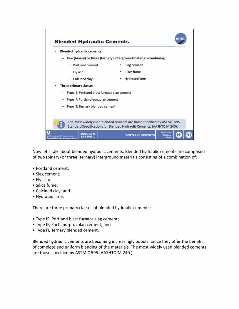
Now let’s talk about blended hydraulic cements. Blended hydraulic cements are comprised of two (binary) or three (ternary) interground materials consisting of a combination of:
• Portland cement;• Slag cement;• Fly ash;• Silica fume;• Calcined clay; and• Hydrated lime.
There are three primary classes of blended hydraulic cements:
• Type IS, Portland blast furnace slag cement;• Type IP, Portland‐pozzolan cement; and• Type IT, Ternary blended cement.
Blended hydraulic cements are becoming increasingly popular since they offer the benefit of complete and uniform blending of the materials. The most widely used blended cements are those specified by ASTM C 595 (AASHTO M 240 ).
Select the best answer. What type of Portland cement would you select for a moderate sulfate environment according to ASTM C 150?
a) Type I;b) Type II;c) Type III;d) Type IV; ore) Type V.

The correct answer is b) Type II. Type II Portland cement has a lower heat of hydration and is moderately sulfate resistant. This cement is used for general construction in areas where there is a possibility of moderate sulfate attack.
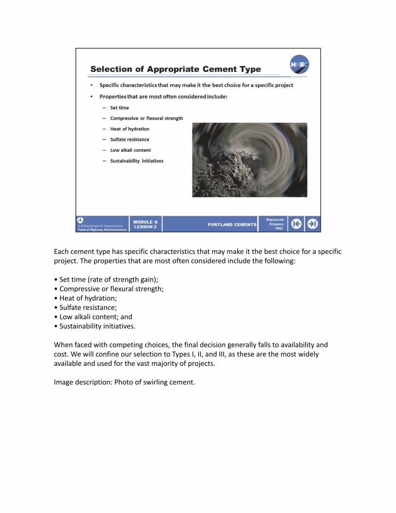
Each cement type has specific characteristics that may make it the best choice for a specific project. The properties that are most often considered include the following:
• Set time (rate of strength gain);• Compressive or flexural strength;• Heat of hydration;• Sulfate resistance;• Low alkali content; and• Sustainability initiatives.
When faced with competing choices, the final decision generally falls to availability and cost. We will confine our selection to Types I, II, and III, as these are the most widely available and used for the vast majority of projects.
Image description: Photo of swirling cement.

The initial set time and rate of strength gain are important for most projects but for different reasons. For instance, in highway construction, the elapsed time before saw cutting joints or the ability to put traffic on the pavement are major considerations. For precast operations, the ability to strip forms for reuse is a prime consideration.
The time to initial set is important because of the time required to haul, place, consolidate, and finish the PCC after batching. Type I or II cements have similar set characteristics and are selected for most projects. Keep in mind that the set time can be altered by the use of accelerating or retarding admixtures and are also influenced by mix design. Type III cements are high early strength but also tend to have a shorter initial set time. Type III cements may pose a problem in hot weather concreting unless adequately retarded.
It should be noted that finely ground Types I, II and I/II cements can behave similarly to a Type III cement.
Image description: Photo of a clock striking midnight.
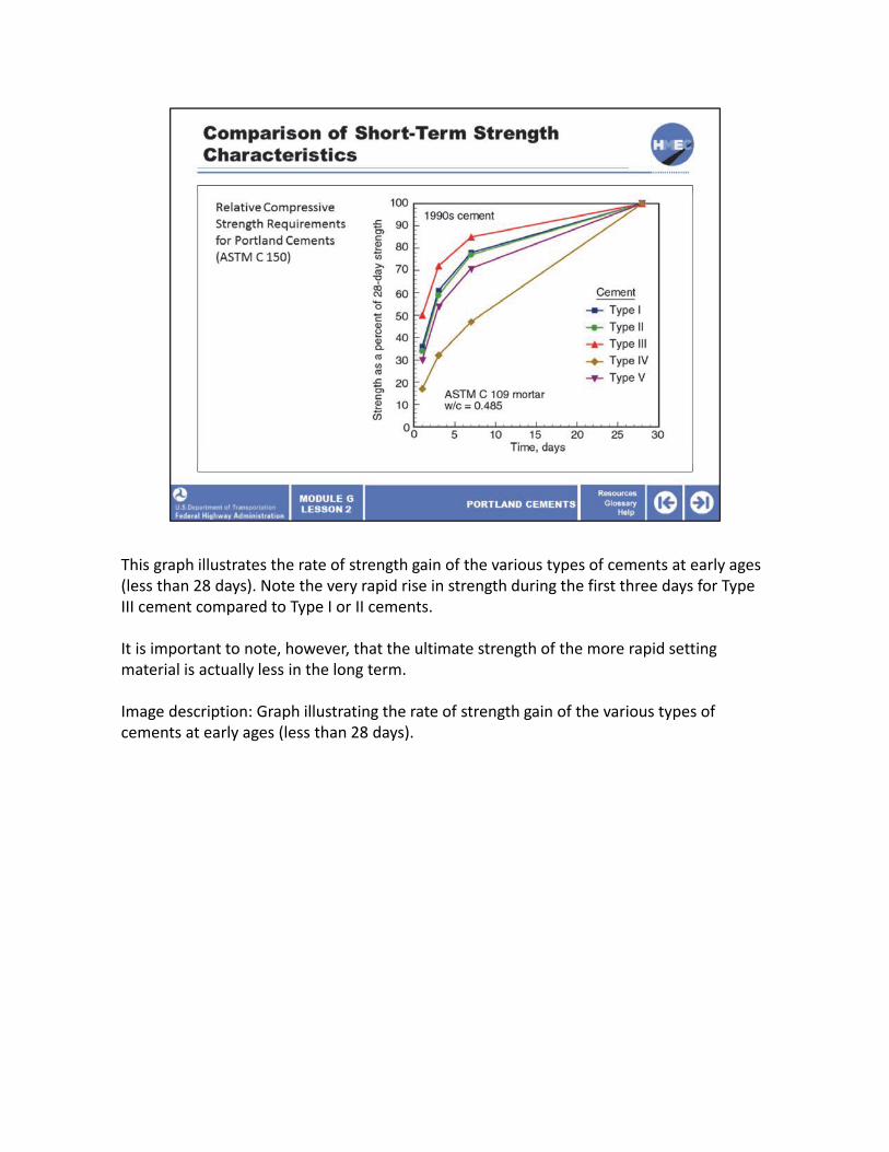
This graph illustrates the rate of strength gain of the various types of cements at early ages (less than 28 days). Note the very rapid rise in strength during the first three days for Type III cement compared to Type I or II cements.
It is important to note, however, that the ultimate strength of the more rapid setting material is actually less in the long term.
Image description: Graph illustrating the rate of strength gain of the various types of cements at early ages (less than 28 days).

The strength of PCC mixes is governed primarily by the mix design, environmental conditions at time of placement, and curing. Factors that effect the strength of PCC mixes and are governed primarily by the mix design include:
• Cement content and type;• Aggregate type and gradation;• Curing; • Water‐cement (W/C) ratio;• Admixtures; and• Temperature and relative humidity at time of placement and during hydration.
The compressive and flexural strengths respond in similar fashions to these variables,which will be discussed later in this lesson. Types I and II cements have similar long‐term strength characteristics. However, Type III cement has a rapid strength gain at early ages (typically less than 90 days) and thereafter results in lower ultimate strength compared with Types I and II.
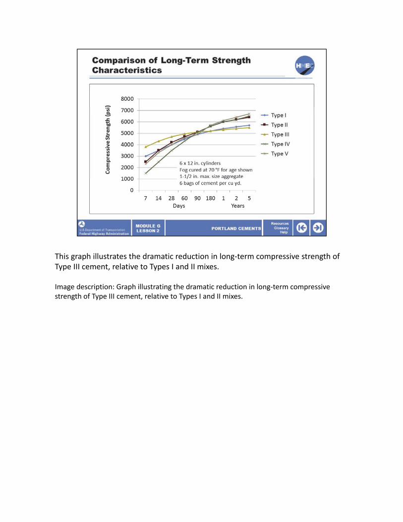
This graph illustrates the dramatic reduction in long‐term compressive strength of Type III cement, relative to Types I and II mixes.
Image description: Graph illustrating the dramatic reduction in long‐term compressive strength of Type III cement, relative to Types I and II mixes.

The heat of hydration is not often considered in cement type selection. However, the temperature of mass placements (temperature gradients) must be low to avoid internal stress build up within the concrete mass that can lead to cracking.
The heat of hydration has traditionally been a consideration primarily for mass concrete placements such as dams. However, this parameter is closely related to the peak temperature rise which may be related to built in curling of concrete pavement slabs. The heat of hydration is intimately tied to the rate of strength gain for most applications (other than mass placement). In other words, Type III cement has a high heat of hydration coupled with the rapid initial strength gain. Type I reacts much more slowly and the heat of hydration is considerably less. Type II cement is engineered to have a moderate heat of hydration. It is important to note that Type II cements may be finely ground (still within specification) and behave more like Type III in their set characteristics.
Type IV has a low heat of hydration but is not readily available.
The use of pozzolans and chemical admixtures can be used to lower the rate of heat evolution.
Image description: Image of a thermometer.

This graph shows a comparison of temperature rise as a function of time for each cement type. Note the high peak temperature associated with Type III cement compared with all other cement types. Type II cement is designed to have a lower heat of hydration and therefore peak temperature rise is significantly lower than Type I. The baseline temperature that the peak temperature rise is calculated against is approximately 77 °F or thereabouts (standard lab temperature).
Image description: Graph showing a comparison of temperature rise as a function of time for each cement type.

Sulfate attack is a deleterious reaction between hardened cement paste (C3AH) and sulfate ions. Sulfates may be present in soils, water, air, or from applied deicing salts. Two types of adverse reactions may occur with sulfate attack:
• Expansion due to growth of ettringite crystals; and• Weakening of the cement paste without expansion—conversion of calcium hydroxide crystals to gypsum.
Type II cement is acceptable for use in moderate sulfate environments and Type V is used in severe sulfate environments. Note that the permeability of the PCC is also a key variable and the w/c ratio should be kept low (less than 0.40). Type I, and particularly Type III, cements are not sulfate resistant and should not be used if sulfates are present without additional mitigation techniques. Note that the addition of pozzolans is a common addition to improve sulfate resistance.
Although Type V has a high sulfate resistance, it is not readily available.
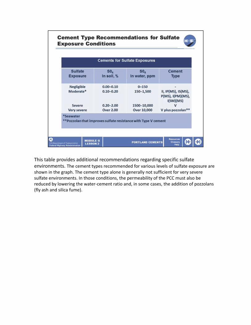
This table provides additional recommendations regarding specific sulfate environments. The cement types recommended for various levels of sulfate exposure are shown in the graph. The cement type alone is generally not sufficient for very severe sulfate environments. In those conditions, the permeability of the PCC must also be reduced by lowering the water‐cement ratio and, in some cases, the addition of pozzolans (fly ash and silica fume).

Low alkali cements should be specified where reactive aggregates are likely to be used in PCC mixes. High alkali cements are problematic in that they may result in alkali‐silica reaction (ASR) or alkali‐carbonate reaction (ACR) deterioration of the PCC under some circumstances. According to the ASTM C 150 specification, the equivalent alkalis content of the cement should be less than 0.60% as determined by laboratory evaluation where reactive aggregates are present. This value will be reported in the mill test report provided by the cement manufacturer. The use of blended cements may be a good alternative to mitigate the potential for ASR.
Mill reports, also known as mill certificates, present the results of the cement manufacturers laboratory analysis of their cement production. Chemical and physical characteristics are presented for a specific length of production run. These reports are sometimes generated on a weekly basis but may represent the aggregate results over a longer period. These reports contain the equivalent alkalis as referenced on the slide.
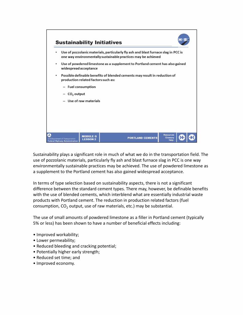
Sustainability plays a significant role in much of what we do in the transportation field. The use of pozzolanic materials, particularly fly ash and blast furnace slag in PCC is one way environmentally sustainable practices may be achieved. The use of powdered limestone as a supplement to the Portland cement has also gained widespread acceptance.
In terms of type selection based on sustainability aspects, there is not a significant difference between the standard cement types. There may, however, be definable benefits with the use of blended cements, which interblend what are essentially industrial waste products with Portland cement. The reduction in production related factors (fuel consumption, CO2 output, use of raw materials, etc.) may be substantial.
The use of small amounts of powdered limestone as a filler in Portland cement (typically 5% or less) has been shown to have a number of beneficial effects including:
• Improved workability;• Lower permeability;• Reduced bleeding and cracking potential;• Potentially higher early strength;• Reduced set time; and• Improved economy.
Select the best answer. What key characteristics should be considered when selecting a Portland cement type?
a) Set time and abrasion resistance;b) Heat of hydration and alkali content;c) Sulfate resistance and color;d) All of the above; ore) None of the above.

The correct answer is b) Heat of hydration and alkali content.
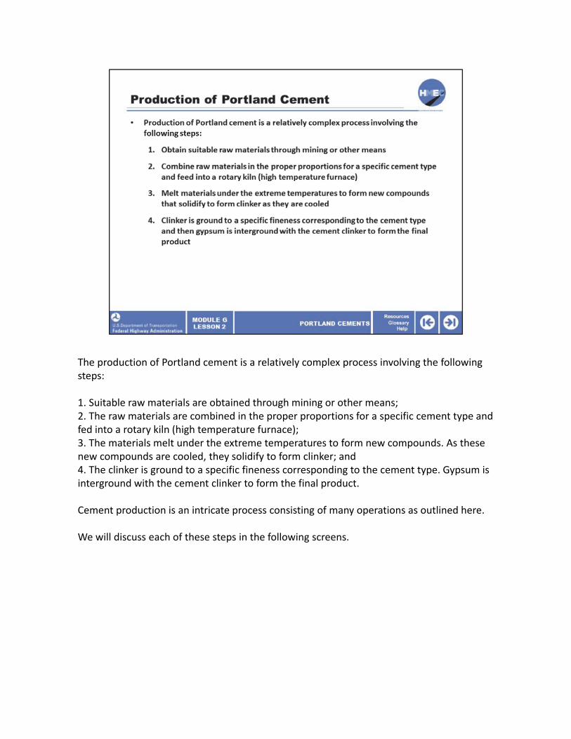
The production of Portland cement is a relatively complex process involving the following steps:
1. Suitable raw materials are obtained through mining or other means;2. The raw materials are combined in the proper proportions for a specific cement type and fed into a rotary kiln (high temperature furnace);3. The materials melt under the extreme temperatures to form new compounds. As these new compounds are cooled, they solidify to form clinker; and4. The clinker is ground to a specific fineness corresponding to the cement type. Gypsum is interground with the cement clinker to form the final product.
Cement production is an intricate process consisting of many operations as outlined here.
We will discuss each of these steps in the following screens.

Rather than write out the oxide forms of these compounds, we will use what is referred to as cement chemist’s shorthand notation.
We will not delve into cement chemistry nor will we discuss the hydration reactions at length. However, it is useful to know the basic chemistry involved in order to identify issues that may occur with incompatibility of materials, set problems, and so on.
As a word of advice, cement chemist nomenclature is unique and if you present this shorthand notation to anyone else, they will likely not know what you are talking about.
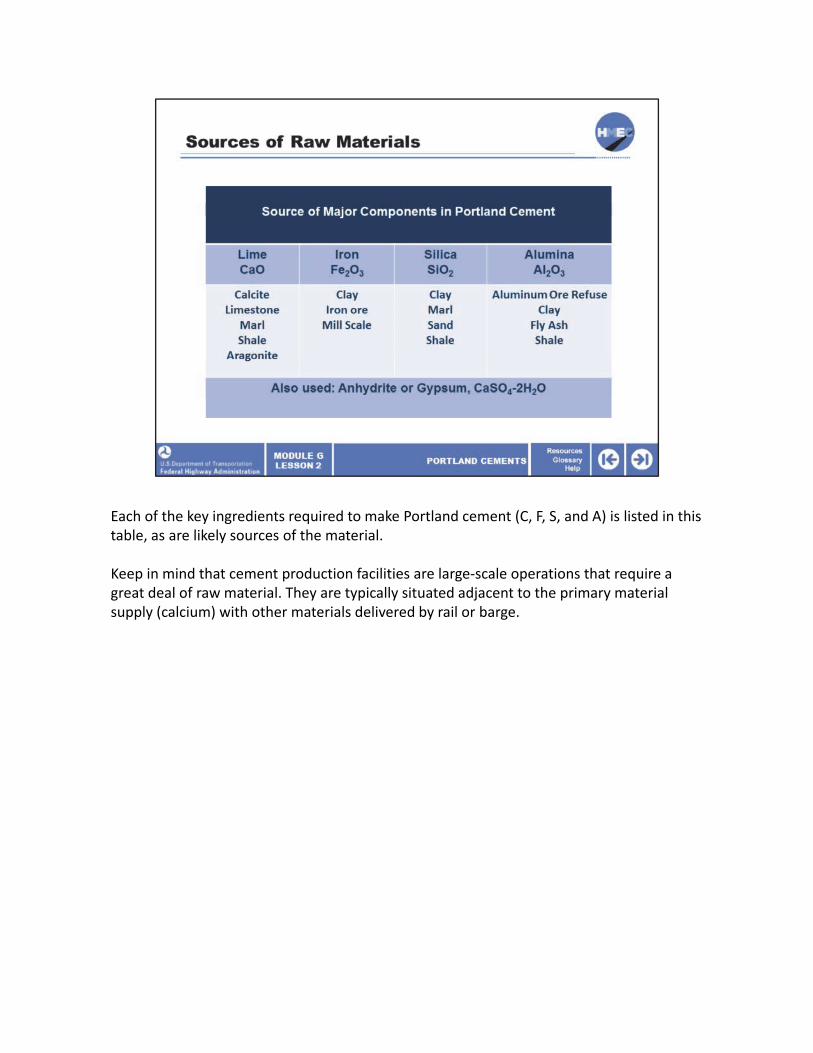
Each of the key ingredients required to make Portland cement (C, F, S, and A) is listed in this table, as are likely sources of the material.
Keep in mind that cement production facilities are large‐scale operations that require a great deal of raw material. They are typically situated adjacent to the primary material supply (calcium) with other materials delivered by rail or barge.

Cement composition comes from the composition and proportions of the raw ingredients.
Depending on the location of the cement manufacturing facility, the majority of the key raw materials will be onsite. However, secondary materials are frequently brought in from remote locations.
As seen in the previous screen, there are many options in the materials used to provide the necessary ingredients (C, S, A, and F).
The mineralogy of these materials must be known to accurately combine them in the correct proportions to produce a specific type of Portland cement that meets the ASTM and AASHTO specifications.
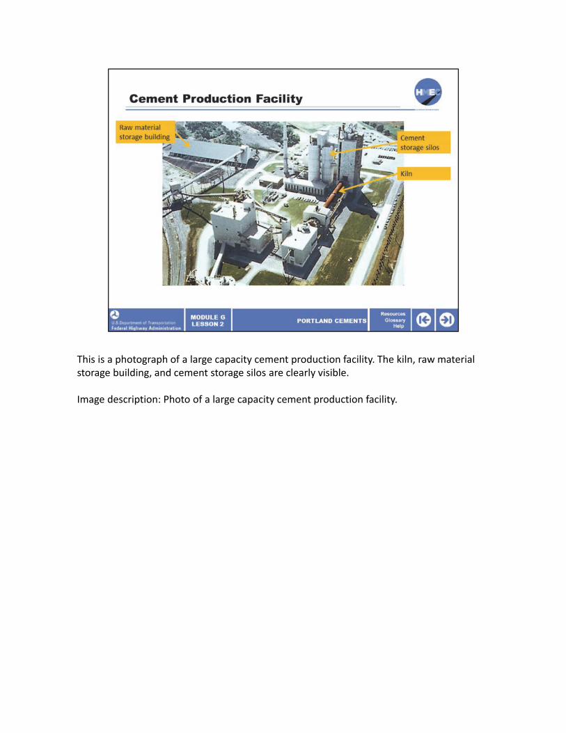
This is a photograph of a large capacity cement production facility. The kiln, raw materialstorage building, and cement storage silos are clearly visible.
Image description: Photo of a large capacity cement production facility.

These are the steps involved in initial processing: combining and grinding the raw materials.
The schematic shows the initial phases of processing prior to entering the actual production feed. There are numerous variations of this set‐up depending on the source of materials.
The crusher shown in the diagram pulverizes the material to less than 5 inches prior to entering the next phase of processing.
Note that both limestone and shale are being fed into the crusher for processing resulting in an initial blend of raw ingredients.
Image description: Schematic showing the initial phases of processing prior to entering the actual production feed.
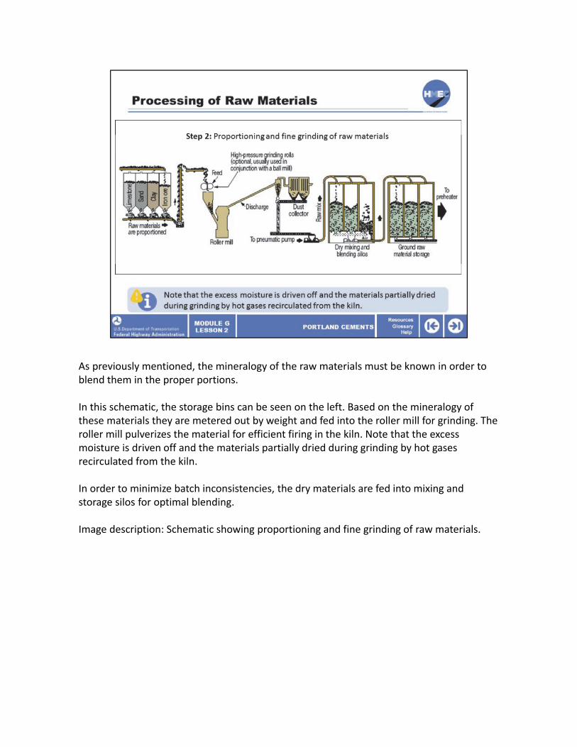
As previously mentioned, the mineralogy of the raw materials must be known in order to blend them in the proper portions.
In this schematic, the storage bins can be seen on the left. Based on the mineralogy of these materials they are metered out by weight and fed into the roller mill for grinding. The roller mill pulverizes the material for efficient firing in the kiln. Note that the excess moisture is driven off and the materials partially dried during grinding by hot gases recirculated from the kiln.
In order to minimize batch inconsistencies, the dry materials are fed into mixing and storage silos for optimal blending.
Image description: Schematic showing proportioning and fine grinding of raw materials.

The feed proportions vary depending on the type of cement being produced. Note that the composition of each of the raw materials must be known so that the overall proportion of the combined materials is correct.
The target feed rate is established by the type of cement being produced. The relative proportion of dry ingredients will vary somewhat depending on changes in the raw feed materials.
The following screens illustrate the actual cement production phase.
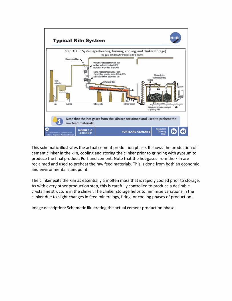
This schematic illustrates the actual cement production phase. It shows the production of cement clinker in the kiln, cooling and storing the clinker prior to grinding with gypsum to produce the final product, Portland cement. Note that the hot gases from the kiln are reclaimed and used to preheat the raw feed materials. This is done from both an economic and environmental standpoint.
The clinker exits the kiln as essentially a molten mass that is rapidly cooled prior to storage. As with every other production step, this is carefully controlled to produce a desirable crystalline structure in the clinker. The clinker storage helps to minimize variations in the clinker due to slight changes in feed mineralogy, firing, or cooling phases of production.
Image description: Schematic illustrating the actual cement production phase.
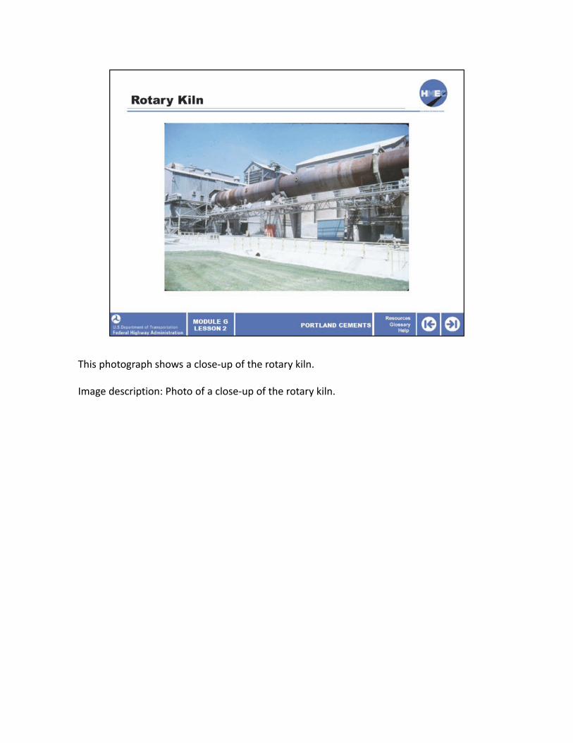
This photograph shows a close‐up of the rotary kiln.
Image description: Photo of a close‐up of the rotary kiln.

This cutaway rendering shows what the inside of the kiln looks like at temperature. Note the focused flame aimed down the center of the kiln.
Image description: Photo of a cutaway rendering showing what the inside of the kiln looks like at temperature.

This is a photograph that shows the actual inside of the kiln at temperature.
Image description: Photo of the inside of a kiln.

This photograph showcases a high production, dual kiln plant.
Image description: Photo of a high production, dual kiln plant.
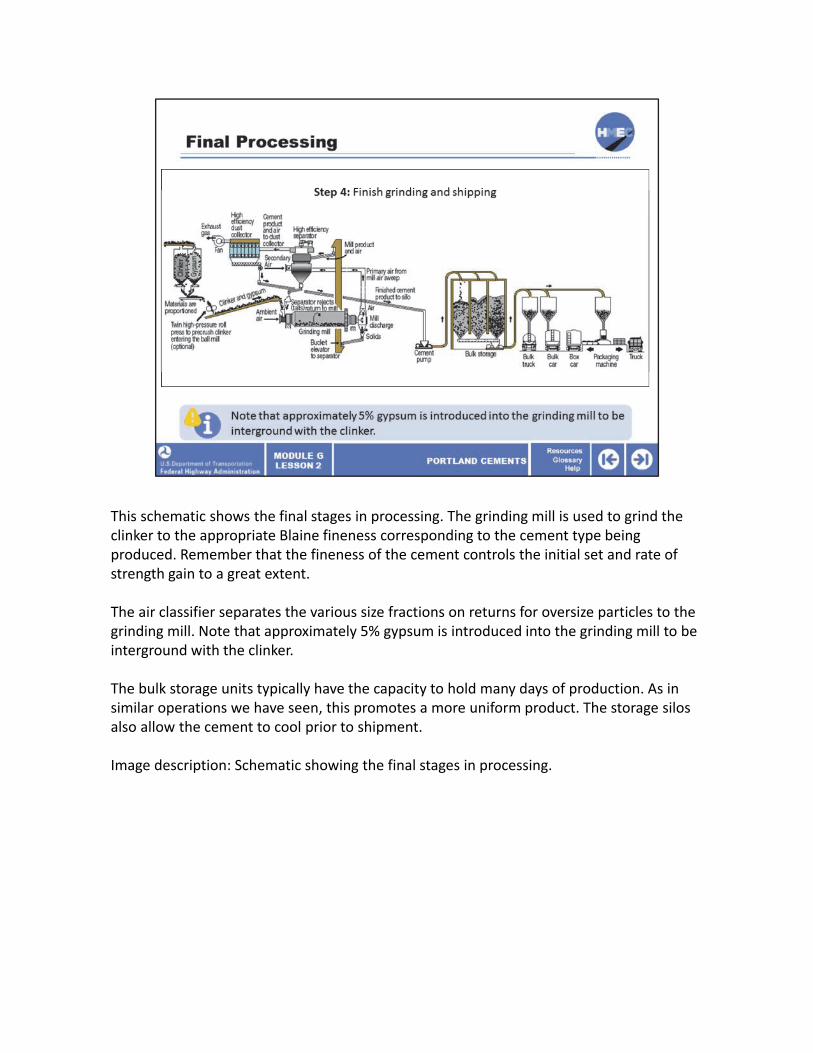
This schematic shows the final stages in processing. The grinding mill is used to grind the clinker to the appropriate Blaine fineness corresponding to the cement type being produced. Remember that the fineness of the cement controls the initial set and rate of strength gain to a great extent.
The air classifier separates the various size fractions on returns for oversize particles to the grinding mill. Note that approximately 5% gypsum is introduced into the grinding mill to be interground with the clinker.
The bulk storage units typically have the capacity to hold many days of production. As in similar operations we have seen, this promotes a more uniform product. The storage silos also allow the cement to cool prior to shipment.
Image description: Schematic showing the final stages in processing.

The grinding mills used to process the clinker are shown in this photograph. Note that the same equipment is capable of producing a wide range of particle fineness, corresponding to the specifications for the different cement types.
Image description: Photo of a grinding mills used to process the clinker.

Note that gypsum (calcium sulfate) is added after the clinker is removed from the kiln and cooled. Gypsum is added to retard the early setting and hardening that would otherwise be triggered by hydration of the C3A. The role of gypsum will be covered in more detail in the next section.
Image description: Photo of gypsum.
Image description: Photo of gypsum.
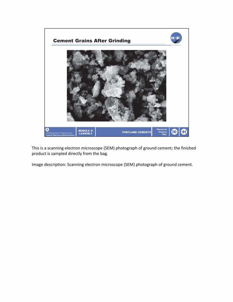
This is a scanning electron microscope (SEM) photograph of ground cement; the finished product is sampled directly from the bag.
Image description: Scanning electron microscope (SEM) photograph of ground cement.
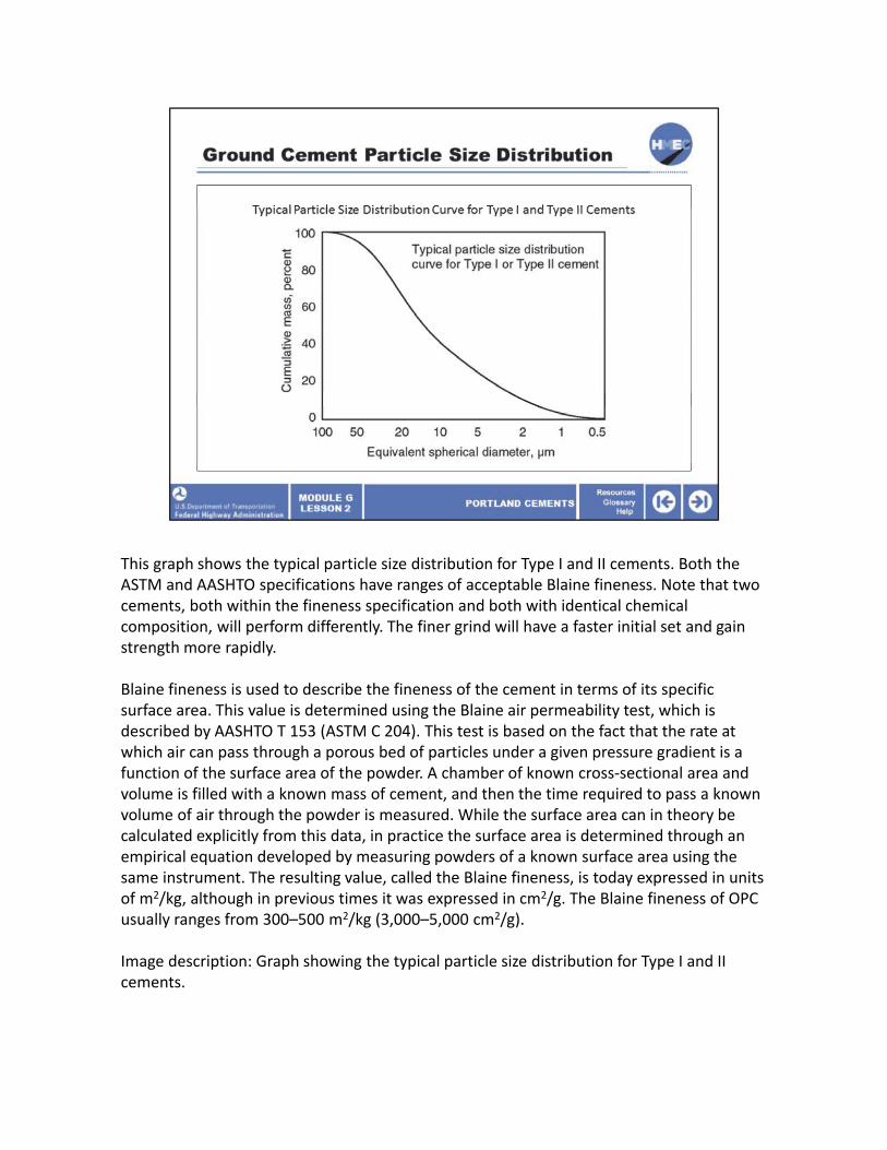
This graph shows the typical particle size distribution for Type I and II cements. Both the ASTM and AASHTO specifications have ranges of acceptable Blaine fineness. Note that twcements, both within the fineness specification and both with identical chemical composition, will perform differently. The finer grind will have a faster initial set and gain strength more rapidly.
Blaine fineness is used to describe the fineness of the cement in terms of its specific surface area. This value is determined using the Blaine air permeability test, which is described by AASHTO T 153 (ASTM C 204). This test is based on the fact that the rate at which air can pass through a porous bed of particles under a given pressure gradient is a function of the surface area of the powder. A chamber of known cross‐sectional area and volume is filled with a known mass of cement, and then the time required to pass a knowvolume of air through the powder is measured. While the surface area can in theory be calculated explicitly from this data, in practice the surface area is determined through an empirical equation developed by measuring powders of a known surface area using the same instrument. The resulting value, called the Blaine fineness, is today expressed in uniof m2/kg, although in previous times it was expressed in cm2/g. The Blaine fineness of OPusually ranges from 300–500 m2/kg (3,000–5,000 cm2/g).
Image description: Graph showing the typical particle size distribution for Type I and II cements.
o
n
ts C

Select the best answer. Which processing equipment determines the fineness of the Portland cement?
a) Cone crusher;b) Kiln;c) Clinker storage unit; ord) Grinding mill.

The correct answer is d) Grinding mill. The grinding mill grinds the cooled cement clinker to the Blaine fineness specified for the specific cement type.

The chemical properties of all standard Portland cement types are similar, the primary difference being the relative percentage of the reactive compounds.
In this section, we will cover the basic chemical transformations (reactions) that occur in the kiln, discuss the reactive compounds that are formed, and how those compounds react during hydration of the cement.
The chemical properties of cement are very involved, and we are only going to look at the most important compounds and reactions. Many construction or materials‐related issues on projects can be traced back to the chemical properties of cement, admixtures, and supplemental cementitious materials.
Image description: Photo of two chemistry beakers sitting on cement cutouts.
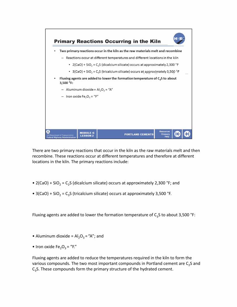
There are two primary reactions that occur in the kiln as the raw materials melt and then recombine. These reactions occur at different temperatures and therefore at different locations in the kiln. The primary reactions include:
• 2(CaO) + SiO2 = C2S (dicalcium silicate) occurs at approximately 2,300 °F; and
• 3(CaO) + SiO2 = C3S (tricalcium silicate) occurs at approximately 3,500 °F.
Fluxing agents are added to lower the formation temperature of C3S to about 3,500 °F:
• Aluminum dioxide = Al2O3 = “A”; and
• Iron oxide Fe2O3 = “F.”
Fluxing agents are added to reduce the temperatures required in the kiln to form the various compounds. The two most important compounds in Portland cement are C2S and C3S. These compounds form the primary structure of the hydrated cement.

There are two important secondary reactions that occur in the kiln as the raw materials melt and then recombine. They are:
• 3(CaO) + Al2O3 = C3A (tricalcium aluminate); and
• 4(CaO)+Al2O3+Fe2O3 = C4AF (tetracalcium aluminoferrite).
Note that fluxing agents are not catalysts since they participate in reactions and are not recoverable. The formations of C3A and C4AF are the result of adding fluxing agents to the kiln.
The presence of C3A is problematic in sulfate environments as it produces a reversible reaction as the sulfate content varies. You might want to review the ASTM C 150 specification regarding allowable C3A contents in sulfate environments. C3A is also responsible for flash setting and requires the addition of interground gypsum to control. Although other compounds are also involved, C3A has the fastest set rate of the four major compounds.

This table represents a typical kiln output in terms of the percentages of the four major compounds.
Note that the relative percentage of each will change as a function of cement type. These compounds form in the kiln at various temperatures and then solidify in the form of cement clinker as the molten mass cools.
The clinker is then processed to produce Portland cement.

The compounds responsible for the formation of the primary structure of hydrated cement include:
• C2S (dicalcium silicate); and • C3S (tricalcium silicate).
When these compounds react with water they form calcium silicate hydrates (C‐S‐H), which are responsible for the majority of the physical attributes of the hydrated cement paste.Calcium hydroxide is also found in the hydrated cement as shown in the table. The structure of the C‐S‐H is the most important factor in determining the strength and durability of the hydrated cement paste. We will not discuss the reactions of the secondary compounds as they are quite complex and, in some instances, reversible.

As can be seen in the graph, the C2S and C3S react at substantially different rates. The initial formation of C‐S‐H is due primarily to the hydration of C3S. Long‐term strength gain is much more a function of the C2S reaction. When discussing the increase in strength of PCC over the span of many years, C2S is the prime contributor.
Note the rate of reaction of the C3A is extremely fast and is kept in check by the addition of the C‐S‐H2 (gypsum).
C4AF is not shown on the graph.
Image description: Graph showing that C2S and C3S react at substantially different rates.

This graph shows the contribution of the four primary compounds as a function of time. Note that after about 14 days, the increase in strength due to the hydration of C3S tends to somewhat level out. On the other hand, the rate of strength gain for the C2S is significantly increased after the first 28 days. In practice, the interrelationship between the compounds makes this much more complex in an actual PCC mix.
Image description: Graph showing the contribution of the four primary compounds as a function of time.
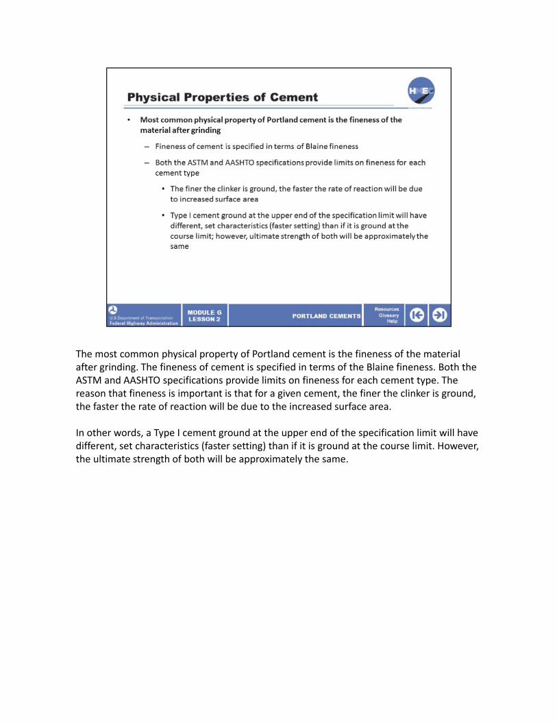
The most common physical property of Portland cement is the fineness of the material after grinding. The fineness of cement is specified in terms of the Blaine fineness. Both the ASTM and AASHTO specifications provide limits on fineness for each cement type. The reason that fineness is important is that for a given cement, the finer the clinker is ground, the faster the rate of reaction will be due to the increased surface area.
In other words, a Type I cement ground at the upper end of the specification limit will have different, set characteristics (faster setting) than if it is ground at the course limit. However, the ultimate strength of both will be approximately the same.

Here are some additional physical properties of cement.The requirement for a minimum compressive strength is self explanatory.
Early stiffening and flash set are important because they have significant implications to field placement of PCC.
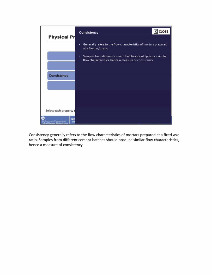
Consistency generally refers to the flow characteristics of mortars prepared at a fixed w/c ratio. Samples from different cement batches should produce similar flow characteristics, hence a measure of consistency.
Specific gravity (generally assumed to be 3.15) is required for volumetric mix design.
Select each property to learn more.
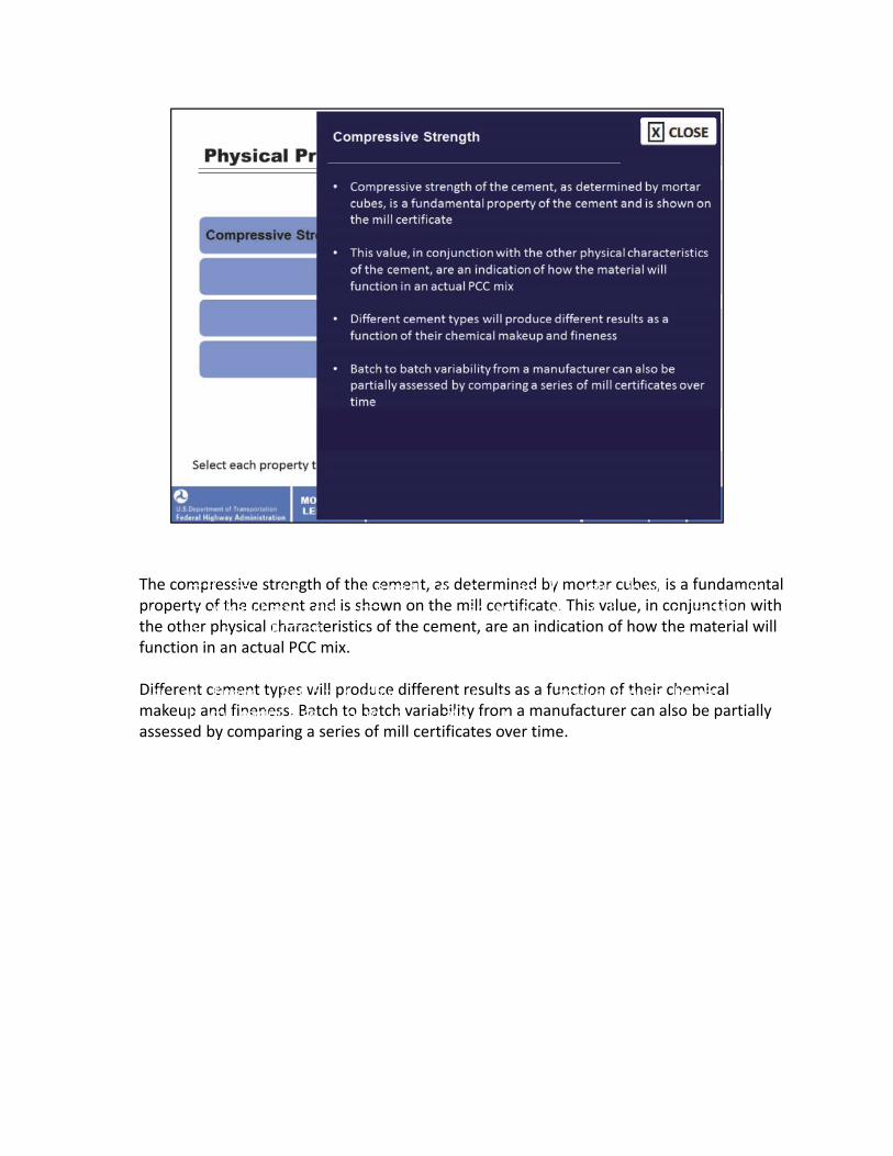
The compressive strength of the cement, as determined by mortar cubes, is a fundamental propertyThe co mprof theessiv cemene stret nandgth isof sho thew cemenn on thet, as mill det certificerminedate. by This mort vaarlue cub, in ecs,onjunction is a fundamen with tal
hepr otheroperty ph ofys theical cemencharactt eandrist icsis sho of thewn cemenon the tmill, are certific an indicate.ation This of va holuwe, thein c omanjunctionterial will with
unctionthe other in an ph actualysical charPCC actmix.eristics of the cement, are an indication of how the material will function in an actual PCC mix.
ifferent cement types will produce different results as a function of their chemical akDifefuper enandt cemen fineness.t types Bat cwillh to pr baoducetch v ariabilitdifferenyt frreomsul tas manufas a functionacturer ofca theirn also chemic be partiallyal ssessedmakeup by and com fineness.paring a Baseriestch to of ba milltc hcertific variabilitatesy ovefromr time.a manufacturer can also be partially assessed by comparing a series of mill certificates over time.
tf
Dma

Flash set refers to a very rapid rate of reaction and stiffening as the cement begins to hydFlashrate inset the ref prersesence to a ve ofry wate rapidr. raThiste ofis reoftaecnti ocanu andsed sbytif ftheening alumina as thet ecemen compoundst begins not to
beinghyd sufrateficien in thetly pr balancedesence of with wate ther. Thisinte risgr oftounden gypsum.caused by This the ca aluminan occurt edue compounds to the not
presencebeing suf off certicienaintly admixbalancedtures, with particularly the interg minerroundal gypsum. admixtur Thises. caHighn occur temper dueat tour esthe also conprtributesencee to of this cert undesirain admixabletur raes,pid particularly set. Flash set miner andal pr admixematurturees. stif Highfening te mperhave aat ures also
significcontributant nege toativ thise impact undesir onable placemen rapid set.t, cFlashonsolida set tandion, pr andema finishing.ture stiffening have a significant negative impact on placement, consolidation, and finishing.
Consistency generally refers to the flow characteristics of mortars prepared at a fixed w/c ratio. Samples from different cement batches should produce similar flow characteristics, hence a measure of consistency.

Specific gravity (generally assumed to be 3.15) is required for volumetric mix design.

Earlier we discussed Blaine fineness. Here is a photo that shows a Blaine Fineness apparatus.
Image description: Photo of a Blaine Fineness apparatus.
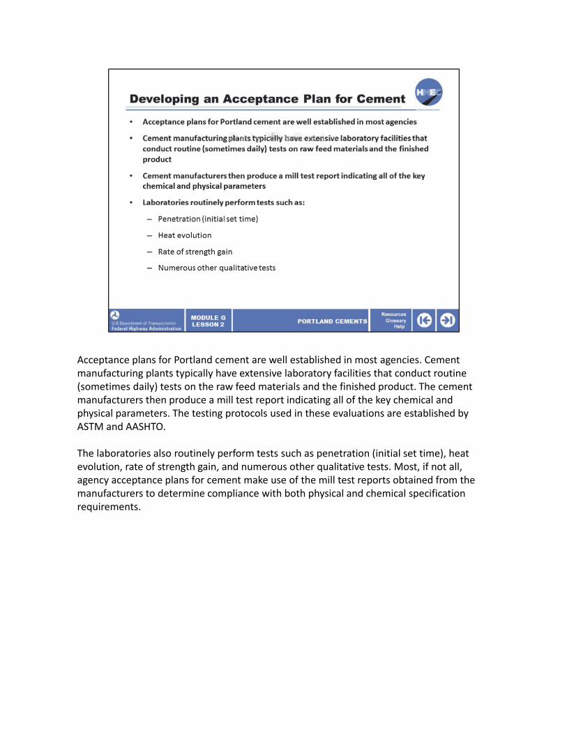
Acceptance plans for Portland cement are well established in most agencies. Cement manufacturing plants typically have extensive laboratory facilities that conduct routine (sometimes daily) tests on the raw feed materials and the finished product. The cement manufacturers then produce a mill test report indicating all of the key chemical and physical parameters. The testing protocols used in these evaluations are established by ASTM and AASHTO.
The laboratories also routinely perform tests such as penetration (initial set time), heat evolution, rate of strength gain, and numerous other qualitative tests. Most, if not all, agency acceptance plans for cement make use of the mill test reports obtained from the manufacturers to determine compliance with both physical and chemical specification requirements.
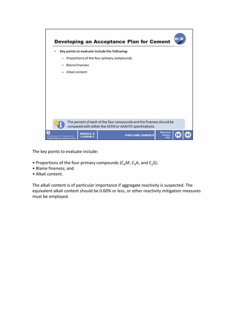
The key points to evaluate include:
• Proportions of the four primary compounds (C4AF, C3A, and C2S);• Blaine fineness; and• Alkali content.
The alkali content is of particular importance if aggregate reactivity is suspected. The equivalent alkali content should be 0.60% or less, or other reactivity mitigation measures must be employed.
Select the best answer. Which one of the following is not a primary compound found in unhydrated Type I cement?
a) C4AF;b) C3A;c) C‐S‐H; ord) C2S.

The correct answer is c) C‐S‐H. C‐S‐H refers to calcium silicate hydrate and is one of the products formed during the hydration reactions.

You have completed Module G, Lesson 2: Portland Cements.
You are now able to:
• Explain the effect of different types of cement on plastic and hardened PCC properties;• Describe the production process for Portland cement;• Relate the chemical and physical properties of Portland cement to the concrete; and• Evaluate chemical and physical properties of Portland cement to the specifications.
Close this lesson and return to the module curriculum to select the next lesson. To close this window, select the “X” in the upper right‐hand corner of your screen.