Ponds: Planning, Design, Construction
51
Transcript of Ponds: Planning, Design, Construction


This handbook describes the require-ments for building a pond. It is useful to thelandowner for general information and alsoserves as a reference for the engineer, tech-nician, and contractor.
In fulfilling their obligation to protect thelives and property of citizens, most states andmany other government entities have laws,rules, and regulations governing the installa-tion of ponds. Those responsible for planningand designing ponds must comply with allsuch laws and regulations. The owner isresponsible for obtaining permits, performingnecessary maintenance, and having the re-quired safety inspections made.
SupercedesPonds for Water Supply and RecreationAgriculture Handbook No. 387January 1971
Issued June 1982Reviewed and approved for reprinting November 1988
All programs and services of the U.S. Department ofAgriculture, Soil Conservation Service, are offered on anondiscriminatory basis, without regard to race, color,national origin, religion, sex, age, marital status, or handicap.

Contents
PageIntroduction 1Water Needs 1Preliminary Investigations 7
General Considerations 7Adequacy of the Drainage Area 8Minimum Pond Depth 8Drainage Area Protection 10Pond Capacity 10Landscape Evaluation 10
Estimating Storm Runoff 11Rainfall Amounts and Expected Frequency 11Hydrologic Groupings of Soils 11Runoff Curve Numbers 15Volume of Storm Runoff 15Peak Discharge Rate 19
Engineering Surveys 19Embankment Ponds 2 0
Detailed Soils Investigation 2 0Spillway Requirements 21Pipes Through the Dam 28Planning an Earthfill Dam 31Staking for Construction 38Building the Pond 39
Excavated Ponds 41Soils 42Spillway and Inlet Requirements 43Planning the Pond 43Building the Pond 4 5
Sealing the Pond 4 6Installing Vegetation 4 9Protecting the Pond 4 9Maintaining the Pond 50Pond Safety 5 1

Introduction
For many years farmers and ranchers havebeen building ponds for livestock water and for irri-gation. By 1980 more than 2.1 million ponds hadbeen built in the United States by land users on pri-vately owned land. More will be needed in thefuture.
The demand for water has increased tremen-dously in recent years, and ponds are one of themost reliable and economical sources of water.Ponds are now serving a variety of purposes, includ-ing water for livestock and for irrigation, fish pro-duction, field and orchard spraying, fire protection,energy conservation, wildlife habitat, recreation,and landscape improvement.
This handbook describes two types of pondsand outlines the requirements for building each.The information comes from the field experienceand observation of land users, engineers, conserva-tionists, and other specialists.
An embankment pond is made by building anembankment or dam across a stream or watercoursewhere the stream valley is depressed enough to per-mit storing 6 feet or more of water. The land slopemay range from gentle to steep.
An excavated pond is made by digging a pit ordugout in a nearly level area. Because the watercapacity is obtained almost entirely by digging, ex-cavated ponds are used where only a small supplyof water is needed. Some ponds are built in gentlyto moderately sloping areas and the capacity is ob-tained both by excavating and by building a dam.
The criteria and recommendations are for damsthat are less than 35 feet high and located wherefailure of the structure will not result in loss of life;in damage to homes, commercial or industrial build-ings, main highways, or railroads; or in interrupteduse of public utilities.
Local information is essential, and land usersare encouraged to consult with specialists experi-enced in building ponds.
Water Needs
Livestock
Clean water and ample forage are equallyessential for livestock to be finished out in a market-able condition. If stockwater provisions in pastureand range areas are inadequate, grazing will beconcentrated near the water and other areas willbe undergrazed. This contributes to serious live-stock losses and instability in the livestock industry.
Watering places must also be properly distrib-uted in relation to the available forage. Areas ofabundant forage may be underused if water is notaccessible to livestock grazing on any part of thata r e a .
Providing enough watering places in pasturesencourages more uniform grazing, facilitates pas-ture improvement practices, retards erosion, andenables farmers to make profitable use of soil-conserving crops and erodible, steep areas unfit forcultivation.
An understanding of stockwater requirementshelps in planning a pond large enough to meet theneeds of the stocks using the surrounding grazingarea. The following tabulation of the average dailyconsumption of water by different kinds of livestockis a guide for estimating water needs:
Kind of livestock Gallons perhead per day
Beef cattle and horses . . . . . . . . . 12 to 15Dairy cows (drinking only) . . . . . . 15Dairy cows (drinking and barn
needs) . . . . . . . . . . . . . . . . . . . . . 35Hogs . . . . . . . . . . . . . . . . . . . . . . . . 4Sheep . . . . . . . . . . . . . . . . . . . . . . . 2
The amount of water consumed at one pond de-pends on the average daily consumption per animal,number of livestock served, and period over whichthey are served.
Irrigation
Farm ponds are now an important source of ir-r i g a t i o n w a t e r p a r t i c u l a r l y i n t h e E a s t ,which does not have the organized irrigation enter-prises of the West. Before World War II, irrigationwas not considered necessary in the humid East.Now many farmers in the East are irrigating theircrops.
Water requirements for irrigation are greaterthat those for any other purpose discussed in thishandbook. The area irrigated from a farm pond islimited by the amount of water available throughoutthe growing season. Pond capacity must be ade-quate to meet crop requirements and to overcomeunavoidable water losses. For example, a 3-inch ap-plication of water on 1 acre requires 81,462 gallons,Consequently, irrigation from farm ponds is usuallylimited to high-value crops on small acreages, usual-ly less than 50 acres.
The required storage capacity of a pond usedfor irrigation depends on these interrelated factors:water requirements of the crops to be irrigated, ef-fective rainfall expected during the growing season,
1

application efficiency of the irrigation method,losses due to evaporation and seepage, and the ex-pected inflow to the pond. Your local SCS conserva-tionist can help you estimate the required capacityof your irrigation pond.
Fish Production
Many land users are finding that fish produc-tion is profitable. A properly built and managedpond can yield from 100 to 300 pounds of fish an-nually for each acre of water surface. A good fishp o n d c a n a l s o p r o v i d e r e c r e a t i o n a n d c a nbe an added source of income should you wishto open it to people in the community for a fee.
Ponds with surface areas of a quarter of anacre to several acres can be managed for good fishproduction. Ponds of less than 2 acres are popularbecause they are less difficult to manage thanlarger ones. You can obtain further informationfrom the U.S. Department of Agriculture Farmers’Bulletin 2250, Warm-Water Fishponds; Farmers’Bulletin 2260, Catfish Farming; and Farmers’ Bulle-tin 2249, Trout Ponds for Recreation.
Field and Orchard Spraying
You may wish to provide water for applyingpesticides to your field and orchard crops. Gener-ally, the amount of water needed for spraying issmall, but it must be available when needed. About100 gallons per acre for each application is enoughfor most field crops. Orchards, however, may re-
quire 1,000 gallons or more per acre for eachspraying.
Provide a means of conveying water from thepond to the spray tank. In an embankment pond,place a pipe in the dam and a flexible hose at thedownstream end to fill the spray tank by gravity. Inan excavated pond, a small pump is needed to fillthe tank.
Fire Protection
A dependable water supply is needed for fight-ing fire. If your pond is located close to your house,barn, or other buildings, provide a centrifugal pumpwith a power unit and a hose long enough to reachall sides of all the buildings. Also provide for one ormore dry hydrants.
Although water-storage requirements for fireprotection are not large, the withdrawal rate forfirefighting is high. A satisfactory fire streamshould be not less than 250 gallons per minute (gpm)with pressure at the nozzle of no less than 50pounds per square inch (psi). Fire nozzles usuallyare 1 inch to 1-1/2 inches in diameter. Use goodquality rubber-lined firehoses, 2-1/2 to 3 inches indiameter. Preferably, the hose should be no morethan 600 feet long.
A typical firehose line consists of 500 feet of3-inch hose and a 1-1/8 inch smooth nozzle. A cen-trifugal pump operating at 83 psi provides astream of 265 gpm with a nozzle pressure of 50 psi.Such a stream running for 5 hours requires 1/4acre-foot of water. If you live in an area protectedby a rural firefighting organization, provide enough
(Not to scale)
Figure 5. Details of a dry hydrant installation.
2

storage to operate several such streams. One acre-foot of storage is enough for four streams.
Your local dealer in pumps, engines, andsimilar equipment can furnish the information youneed about pump size, capacity, and engine horse-power.
Recreation
A pond can provide many pleasant hours ofswimming, boating, and fishing. The surroundingarea can be made into an attractive place forpicnics and games.
Many land users realize additional income byproviding water for public recreation. If the publicis invited to use a pond for a fee, the area must belarge enough to accommodate several parties en-gaged in whatever recreation activities are pro-vided.
If a pond is to be used for public recreation,supply enough water to overcome evaporation andseepage losses and to maintain a desirable waterlevel. A pond to be used for swimming must be freeof pollution and have an adequate depth of waternear a gently sloping shore. Also needed are mini-mum facilities for public use and safety such as ac-cess roads, parking areas, boat ramps or docks,fireplaces, picnic tables, drinking water, and sani-tary facilities.
To protect public health, most states have lawsand regulations that require water supplies to meetcertain prescribed standards if they are to be usedfor swimming and human consumption. Generally,water must be tested and approved before publicuse is permitted. There are also rules and regula-tions for building and maintaining public sanitaryfacilities. The state board of health or a similaragency administers such laws and regulations. Con-tact your local health agency to become familiarwith those regulations before making extensiveplans to provide water for public recreation.
Waterfowl and Other Wildlife
Ponds attract many kinds of wildlife. Migratorywaterfowl often use ponds as resting places in theirflights to and from the North. Ducks often use north-ern ponds as breeding places, particularly wherethere is an ample supply of food.Upland game birds use ponds as watering places.
Landscape Quality
Water adds variety to a landscape and furtherenhances its quality. Reflections in water attract
the eye and help to create a contrast or focal pointin the landscape. A pond visible from a home,patio, or entrance road increases the at trac-tiveness of the landscape and often improves landvalue. Ponds in rural, suburban, and urban areashelp to conserve landscape quality.
Regardless of its purpose, a pond’s appearancecan be improved by using principles of landscapearchitecture and design techniques. Good design in-cludes consideration of size, site visibility, relation-ship to the surrounding landscape and use patterns,and shoreline configuration.
Your local SCS conservationist can help youapply basic principles of landscape architecture.You should consult a landscape architect for addi-tional information and special designs.
Multiple Purposes
You may wish to use the water in your pond formore than one purpose; for example, to providewater for livestock, fish production, and sprayingfield crops. If so, two additional factors must beconsidered.
First, in estimating your water requirementsyou must total the amounts needed for each purposeand be sure that you provide a supply adequate forall the intended uses.
Second, make sure that the purposes for whichthe water is to be used are compatible. Some com-binations, such as irrigation and recreation, gen-erally are not compatible. You would probably usemost of the water during the irrigation season, mak-ing boating and swimming impractical.
Ponds used temporarily for grade control or assediment basins associated with construction sitescan be converted later into permanent ponds bycleaning out the sediment, treating the edge, andadding landscape measures. If a sedimentbasin is to be cleaned and reconstructed as awater element, the standards forbe used.
Preliminary Investigations
General Considerations
dam design should
Selecting a suitable site for your pond is im-portant, and preliminary studies are needed beforefinal design and construction. If possible, considermore than one location and study each one to selectthe most practical, esthetic, and economical site.
For economy, locate the pond where the largest
3

storage volume can be obtained with the leastamount of earthfill. A good site usually is one wherea dam can be built across a narrow section of avalley, the side slopes are steep, and the slope ofthe valley floor permits a large area to be flooded.Such sites also minimize the area of shallow water.Avoid large areas of shallow water because of ex-cessive evaporation and the growth of noxiousaquatic plants.
If farm ponds are used for watering livestock,make a pond available in or near each pasture orother grazing unit. Forcing livestock to travel longdistances to water is detrimental to both the live-stock and the grazing area. Space watering placesso that livestock do not have to travel more than aquarter of a mile to reach a pond in rough, brokencountry or more than a mile in smooth, nearly levelareas. Well-spaced watering places encourage uni-form grazing and facilitate grassland management.
If pond water must be conveyed for use else-where, such as for irrigation or fire protection,locate the pond as close to the major water use aspracticable. Conveying water is expensive and, ifdistance is excessive, the intended use of the watermay not be practical.
Ponds for fishing, boating, swimming, or otherforms of recreation must be reached easily by auto-mobile, especially if the general public is charged afee to use the pond. The success of an income-producing recreation enterprise often depends onaccessibility.
Avoid pollution of pond water by selecting alocation where drainage from farmsteads, feedlots,corrals, sewage lines, mine dumps, and similarareas does not reach the pond.
Do not overlook the possibility of failure of thedam and the resulting damage from sudden releaseof water. Do not locate your pond where failure ofthe dam could cause loss of life; injury to persons orlivestock; damage to residences, industrial build-ings, railroads, or highways; or interrupted use ofpublic utilities. If the only suitable pond sitepresents one or more of these hazards, hire anengineer to reduce the possibility of failure from im-proper design or construction.
Be sure that no buried pipelines or cables crossa proposed pond site, They could be broken or punc-tured by the excavating equipment, which can resultnot only in damage to the utility but also in injury tothe operator of the equipment. If it is necessary touse a site crossed by pipelines or cable, you mustnotify the utility company before starting construc-tion and obtain permission to dig.
Avoid sites under powerlines. The wires maybe within reach of a fishing rod held by someonefishing from the top of the dam.
4
Adequacy of the Drainage Area
For ponds where surface runoff is the mainsource of water, the contributing drainage areamust be large enough to maintain water in the pondduring droughts. However, the drainage area shouldnot be so large that expensive overflow structuresare needed to bypass excess runoff during storms.
The amount of runoff that can be expected an-nually from a given watershed depends on so manyinterrelated factors that no set rule can be given forits determination. The physical characteristics thatdirectly affect the yield of water are relief, soil in-filtration, plant cover, and surface storage. Stormcharacteristics such as amount, intensity, and dura-tion of rainfall also affect water yield. These char-acteristics vary widely throughout the United States.Each must be considered before determining thewatershed area requirements for a particular pondsite.
Figure 10 is a general guide for estimating theapproximate size of drainage area needed for adesired water-storage capacity. For example, apond located in west-central Kansas with a capacityof 5 acre-feet requires a drainage area of at least175 acres under normal conditions. If reliable localrunoff information is available, use it in preferenceto the guide.
Average physical conditions in the area areassumed to be the normal runoff-producing charac-teristics for a drainage area, such as moderateslopes, normal soil infiltration, fair to good plantcover, and normal surface storage.
To apply the information given in figure 10,some adjustments may be necessary to meet localconditions. Modify the values in the figure for drain-age areas having characteristics other than normal.Reduce the values by as much as 25 percent fordrainage areas having extreme runoff-producingcharacteristics. Increase them by 50 percent ormore for low runoff-producing characteristics.
Minimum Pond Depth
To ensure a permanent water supply, the watermust be deep enough to meet the intended userequirements and to offset probable seepage andevaporation losses. These vary in different sectionsof the country and from year to year in any one sec-tion. Figure 11 shows the recommended minimumdepth of water for ponds if seepage and evapora-tion losses are normal. Deeper ponds are neededwhere a permanent or year-round water supply isessential or where seepage losses exceed 3 inchesper month.
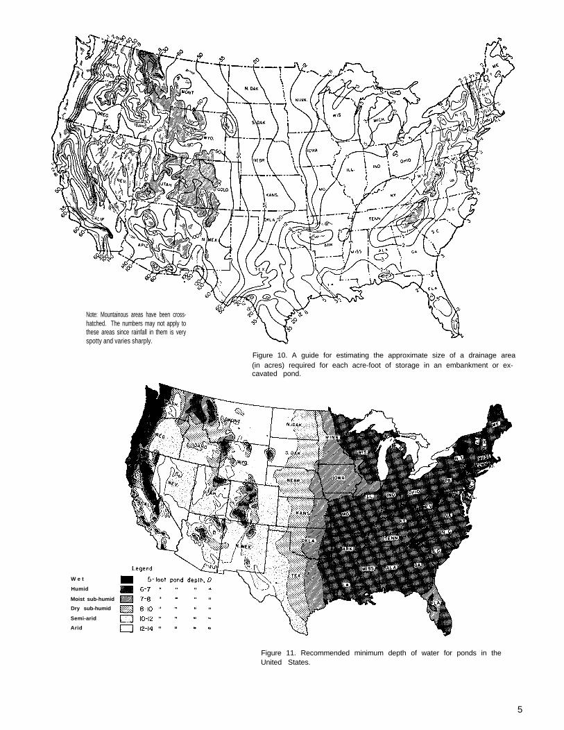
Note: Mountainous areas have been cross-hatched. The numbers may not apply tothese areas since rainfall in them is veryspotty and varies sharply.
Figure 10. A guide for estimating the approximate size of a drainage area(in acres) required for each acre-foot of storage in an embankment or ex-cavated pond.
W e t
Humid
Moist sub-humid
Dry sub-humid
Semi-arid
Arid
Figure 11. Recommended minimum depth of water for ponds in theUnited States.
5

Drainage Area Protection feet (0.4 x 3.2 x 12.5 = 16 acre-feet) (1 acre-foot= 325,851 gallons).
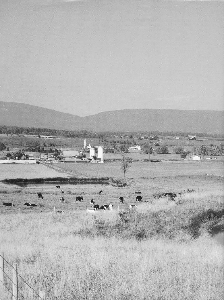
To maintain the required depth and capacity ofa pond, the inflow must be reasonably free of siltfrom an eroding watershed. The best protection isadequate erosion control on the contributing drain-age area. Land under permanent cover of trees orgrasses is the most desirable drainage area (fig. 12).If such land is not available, use cultivated areasprotected by conservation practices such as terra-cing, contour tillage, stripcropping, or conservationcropping systems.
If an eroding or inadequately protected water-shed must be used to supply pond water, delay pondconstruction until conservation practices are estab-lished. In any event, protection of the drainage areashould be started as soon as you decide to build apond.
Pond Capacity
Estimate pond capacity to be sure that enoughwater is stored in the pond to satisfy the intendeduse requirements. A simple method follows:
Establish the normal pond-full water elevationand stake the waterline at this point. Measure thewidth of the valley at this elevation at regular inter-vals and use these measurements to compute thepond-full surface area in acres. Multiply the surfacearea by 0.4 times the maximum water depth in feetmeasured at the dam. For example, a pond with asurface area of 3.2 acres and a depth of 12.5 feet atthe dam has an approximate capacity of 16 acre-
Landscape Evaluation
Alternative pond sites should be evaluated forpotential visibility and compatibility with surround-ing landscape characteristics and use patterns (fig.13). Identify major viewpoints (points from whichthe site is viewed) and draw the important sightlines with cross sections, where needed, to deter-mine visibility. If feasible, locate the pond so thatthe major sight line crosses the longest dimension ofwater surface. The pond should be placed so that aviewer will see the water first before noticing thedam, pipe inlet, or spillway. Often, minor changes inthe dam alignment and spillway location can shiftthese elements out of view and reduce their promi-nence.
If possible, locate your pond so that some exist-ing trees and shrubs remain along part of the shore-line. The vegetation will add interest by castingreflections on the water, will provide shade on sum-mer days, and will help blend the pond into the sur-rounding landscape. Often it is possible to locate ordesign a pond so that an island can be created forrecreation, wildlife habitat, or visual interest.
In addition to the more typical farm and resi-dential sites, ponds can be located in landscapes ofpoor quality to rehabilitate abandoned road borrowareas, dumping sites, abandoned rural mines, andother low production areas.
Figure 12. Land with permanentvegetation makes the mostdesirable drainage area.
6

Estimating Storm Runoff
The amount of precipitation, whether it occursas rain or snow, is the potential source of waterthat may run off small watersheds. The kind of soiland the type of vegetation affect the amount ofwater that runs off. Terraces and diversions, alongwith steepness and shape of a watershed, affect therate at which water runs off.
A spillway is provided to bypass surface runoffafter the pond is filled. Use the following tables andcharts to estimate the peak discharge rates for thespillway. They provide a quick and reliable estimateof runoff rates and associated volumes for a rangeof storm rainfall amounts, soil groups, land use,cover conditions, and average watershed slopes.The peak discharge rates in the charts were com-puted by automatic data processing equipment us-ing SCS national procedures.
Rainfall Amounts and Expected Frequency
Maps showing the amount of rainfall expectedin a 24-hour period have been reproduced in figures14-1, 14-2, and 14-3 (pp. 8-10) from the U.S.Weather Bureau Technical Paper 40 (USWP-TP-40),
Figure 13. A preliminary study oftwo alternative sites for a pondto be used for livestock water,irrigation, and recreation.
Rainfall Frequency Atlas of the United States. Morespecific rainfall information for areas west of the105th meridian is in the Precipitation FrequencyAtlas of the Western United States (NOAA Atlas 2).
It is impractical to design an ordinary pondspillway to accommodate the peak rate of runofffrom the most intense rainstorm ever known or an-ticipated. The spillway for an ordinary farm pond isusually designed to pass the runoff from a 25-yearfrequency storm (fig. 14-2). This means a storm withonly a 4-percent chance of occurring in any year orthe size beyond which larger storms would not oc-cur more often than an average of once in 25 years.Designing for a 50-year storm frequency is recom-mended for spillways for larger dams. A 10-yearstorm frequency may be adequate for sizing thespillway in very small ponds.
Hydrologic Groupings of Soils
Soils have been classified in four hydrologicgroups according to infiltration and transmissionrates:
A: These soils have a high infiltration rate.They are chiefly deep, well-drained sands orgravels. They have low runoff potential.
Pond A: Easily accessible to house for recreation, to barn for
* Viewpointslivestock water, and to garden for irrigation.Visible from house and road.
-- Sight linesPond B: Too remote for all needs. Vegetation must be removedfor construction and for view from house.
7

. C
8

CONTERMINOUS UNITED STATES1. . .— . . . - -
Prepared by U. S. Weather Bureau
Figure 14-2. Rainfall amounts from a 24-hour storm based on 25-yearfrequency.
9

CONTERMINOUS UNITED STATES. _
Figure 14-3, Rainfall amounts from a 24-hour storm based on 50-yearfrequency.
1 0

B. These soils have a moderate infiltration ratewhen thoroughly wet. They are chiefly moderatelydeep, well-drained soils of moderately fine tomoderately coarse texture.
C. These soils have a slow infiltration ratewhen wet. They are soils with a layer that impedesdownward movement of water and soils of moderate-ly fine to fine texture.
D. These soils have a very slow infiltrationrate. They are chiefly clay soils with a high swellingpotential, soils with a permanent high water table,soils with a claypan at or near the surface, andshallow soils over nearly impervious material. Theyhave high runoff potential.
The SCS district conservationist or your countyextension agent can help you classify the soils for agiven pond site in one of the four hydrologic groups.
Runoff Curve Numbers
A numerical runoff rating is shown in table 1for a range of soil-use-cover complexes. Becausethese numbers relate to a set of curves developedfrom the SCS runoff equation, they are referred toas curve numbers in table 2 and on figure 15 (pp.12-14). Figure 15 is a set of three charts that showthe peak rates of discharge by slope for a range ofcurve numbers.
The watershed above a farm pond often con-tains areas represented by different curve numbers.A weighted curve number can be obtained based onthe percentage of area for each curve number. Forexample, assume that the watershed above a pondis mainly (three-fourths) in good pasture and a soilin hydrologic group B. The remainder is cultivated
Table 2.—Runoff depth in inches
with conservation treatment on a soil in hydrologicgroup C. According to table 1, three-fourths of thewatershed has a 61 curve number and the otherone-fourth a 78 curve number.
A weighted curve number for the total water-shed would be :
3/4 x 61 = 46 (approximately)1/4 x 78 = 20 (approximately)Weighted = 66
Volume of Storm Runoff
Often it is good to know how much water runsoff from a big storm as well as the rate at which itflows. The volume is also needed to compute thepeak discharge rate.
The figures in table 2 are the depth (in inches)at which the storm runoff, if spread evenly, would
Table 1 .—Runoff curve numbers
Hydrologic soil group
A B C D
Cultivated:Without conservation treatment . . . . . . 72 81 88 91With conservation treatment 62 71 78 81
Pasture or range:Poor cover . . . . . . . . . . . . . . . . . . . . . . . . . 68 79 66 89Good cover . . . . . . . . . . . . . . . . . . . . . . .. 139 61 74 80
Meadow . . . . . . . . . . . . . . . . . . . .................. .. .130 158 71 78
Woods, shrubs, or forest:Thin stand, poor cover, no mulch . . . . . . 145 66 77 83Good cover . . . . . . . . . . . . . . . . . . . . ... .125 155 70 77
Farmsteads . . . . . . . . . . . . . . . . . . . . . . . . . . 159 74 82 86
Roads . . . . . . . . . . . . . . . . . . . . . . . . . . . . . . 74 84 90 921The italicized curve numbers are less than any in figure 15
or table 2. Use the weighted curve number of 60 for these con-ditions.
Rainfall Curve number(inches) 60 65 70 75 80 85 90
1.0 0 0 0 0.03 0.081.2
0.17 0.320 0 .03 .07 .15
1.4 0.28
.02.46
.06 .13 .24 .391.6 .01 .05
.61.11 .20 .34
1.8 .03.52 .76
.09 .17 .29 .44 .65 .93
2.0 .06 .14 .24 .382.5
.56 .80 1.09.17 .30 .46 .65
3.0.89
.331.18 1.53
.51 .72 .96 1.254.0 .76
1.591.03
1.981.33 1.67 2.04
5.02.46 2.92
1.30 1.65 2.04 2.45 2.89 3.37 3.88
6.0 1.92 2.35 2.87 3.28 3.787.0 2.60
4.313.10
4.853.62 4.15 4.69
8.0 3.335.26
3.905.82
4.47 5.04 5.629.0 4.10
6.22 6.814.72 5.34 5.95 6.57
10.0 4.907.19 7.79
5.57 6.23 6.88 7.52 8.16 8.78
11.0 5.72 6.44 7.13 7.82 8.4812.0 6.56
9.147.32
9.778.05 8.76 9.45 10.12 10.76
11

1000900800700600500
400
300
200
40
30
20
3
TYPE II STORM
DRAINAGE AREA (ACRES)
Figure 15-1. Peak rates of discharge for small watersheds on flat slopes(24-hour, type-II storm distribution).
1 2

”
700600500
600
300
TYPE II STORM
DRAINAGE AREA (ACRES)
Figure 15-2. Peak rates of discharge for small watersheds on moderateslopes (24-hour, type-II storm distribution).
13
1000900800700600
500
400
300
200
10090807060
50
40
30
m
109876
5
4
3
2
1
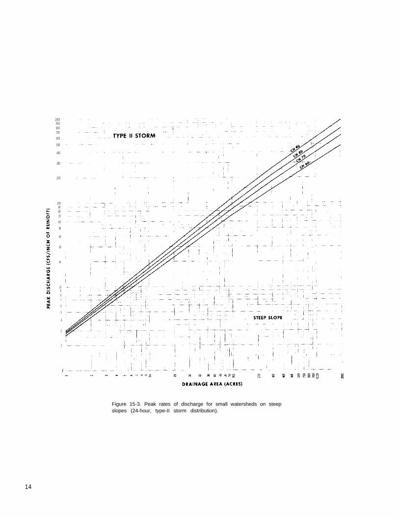
Figure 15-3. Peak rates of discharge for small watersheds on steepslopes (24-hour, type-II storm distribution).
14

cover the entire watershed. For example, thevolume of runoff from a 3-inch rainfall on a100-acre watershed with the weighted curve num-ber of 66 would be:
0.55 inch (interpolated between 0.51 and 0.72inches)
100 acres x 0.55 inch = 55 acre-inches
55 acre-inches ÷ 12 = 4.55 acre-feet
55 acre-inches x 27,154 gallons per acre-inch= 1.5 million gallons (approximately)
Peak Discharge Rate
The slope of the land above the pond affectsthe peak discharge rate significantly. The rates infigure 15 are for flat, moderate, and steep slopes.Data in published soil surveys give the averagewatershed slope at most locations. Generally theaverage slope can be judged closely enough to placethe watershed in one of the three slope categoriesof figure 15. Table 3 shows the range in slopes.
The rate at which storm runoff passes throughthe spillway of a farm pond is measured in cubicfeet per second (cfs). (This can also be expressed asf t3/sec.) The vertical scale of the charts in figure 15shows the cubic feet of water per inch of runoffthat must pass through the spillway every second.To determine this rate, first find the chart for theappropriate watershed slope. Then follow the chartalong the base at the size of the area that drainsinto the pond. Move vertically to the curve number.Read the peak discharge rate in cfs per inch of run-off along the vertical scale. The volume of runoff isobtained by entering table 2 with the 24-hour rain-fall from figure 14 and the curve number. The peakdischarge rate in cfs is the discharge rate fromfigure 15 multiplied by the volume of runoff fromtable 2. These discharge rates are for the intensesummer thunderstorms that are common throughoutmost of the United States.
The maritime climate along the Pacific coastside of the Sierra Nevada and the Cascade Moun-tains in California, Oregon, and Washington haswinter rainfall of less intensity. The peak dischargerate for these areas in about 25 percent of thatshown in the charts of figure 15.
The following example illustrates how to usetables 2 and 3 and figures 14 and 15 to obtain thepeak discharge rate for estimating the capacityneeded in the spillway.
Given (1) a 90-acre watershed in Salem Countyin southern New Jersey; (2) it has moderate water-
shed slopes; (3) the soils shown on the Salem Countysoil map are in hydrologic soil group C; and (4) thelandscape is meadow. The spillway should be largeenough to pass the runoff from a 25-year frequencyrainstorm. Figure 14-2 shows that the 24-hour,25-year frequency rainfall is about 6 inches. Therunoff curve number for meadow and hydrologicsoil group C is 71 (table 1). In figure 15-2, themoderate slope and curve number 71 shows about50 cfs per inch of runoff for a 90-acre drainagearea.
According to table 2, for 6 inches of rainfalland a curve number of 71 the volume of runoff is2.95 inches, The peak discharge for construction ofthe spillway is 50 x 2.95 = 148 cfs.
Engineering Surveys
Once you determine the probable location ofthe pond, make enough engineering surveys to planthe dam, spillway, and other features. For mostponds the surveys needed are simple, but if you arenot familiar with the use of surveying instrumentsyou should employ an engineer.
Pond surveys usually consist of a profile of thecenterline of the dam, a profile of the centerline ofthe earth spillway, and enough measurements toestimate pond capacity. A simple method of estimat-ing pond capacity is described on page 10. Forlarger and more complex ponds, particularly thoseused to store water for irrigation, you may need acomplete topographic survey of the entire pond site.
Run a line of profile levels along the centerlineof the proposed dam and up both sides of the valleywell above the expected elevation of the top of thedam and well beyond the probable location of theearth spillway. The profile should show surfaceelevations at all significant changes in slope and atintervals of no more than 100 feet. This line oflevels establishes the height of the dam and thelocation and elevation of the earth spillway and thetrickle tube. It is used to compute the volume ofearth needed to build the dam.
Run a similar line of profile levels along thecenterline of the earth spillway. Start from a pointon the upstream end that is well below the selected
Table 3.—Slopes for peak discharge
Slope category Average slope Actual slope used inrange figure 15 computations
pct pctFlat . . . . . . . . . . . . . . 0 to3 1Moderate . . . . . . . . . . 3 to 8 4Steep . . . . . . . . . . . . . 8 and above 1 6
1Level to nearly level.
15

normal water surface elevation and continue to apoint on the downstream end where water can besafely discharged without damage to the dam. Thisline serves as a basis for determining the slope anddimensions of the spillway.
All surveys made at a pond site should be tiedto a reference point called a bench mark. This maybe a large spike driven into a tree, an iron roddriven flush with the ground, a point on the con-crete headwall of a culvert, or any object that willremain undisturbed during construction of the dam.
Embankment Ponds
Detailed Soils Investigation
Soils in the Ponded Area. Suitability of a pondsite depends on the ability of the soils in the reser-voir area to hold water. The soil should contain alayer of material that is impervious and thickenough to prevent excessive seepage. Clays andsilty clays are excellent for this purpose; sandyclays are usually satisfactory. Coarse-texturedsands and sand-gravel mixtures are highly perviousand therefore usually unsuitable. The absence of alayer of impervious material over part of the pondedarea does not necessarily mean that you must aban-don the proposed site. You can treat these parts ofthe area by one of several methods described laterin this handbook (p. 42). Any of these methods canbe expensive.
Some limestone areas are especially hazardousas pond sites. There may be crevices, sinks or chan-nels in the limestone below the soil mantle that arenot visible from the surface. These may emptythe pond in a short time. In addition, many soils inthese areas are granular. Since the granules do not
Figure 16. Borrow material taken from within thereservoir area creates an irregular pond con-figuration.
break down readily in water, the soils remain highlypermeable. Without extensive investigations andlaboratory tests it is difficult to recognize all thefactors that may make a limestone site undesirable.The best clue to the suitability of a site in one ofthese areas is the degree of success others havehad with farm ponds in the immediate vicinity.
Make soil borings at intervals over the area tobe covered with water unless you know that thesoils are sufficiently impervious and that leakagewill not be a problem. Three or four per acre maybe enough if the soils are uniform. More may be re-quired if there are significant differences.
Foundation Conditions. The foundation under adam must (1) ensure stable support for the struc-ture, and (2) provide the necessary resistance to thepassage of water.
Investigate thoroughly the foundation conditionsunder the proposed dam site by making soil borings.Study the natural banks (abutments) at the ends ofthe dam as well as the supporting materials underthe dam. If the dam is to be placed on rock, the rockmust be examined for thickness and for fissures andseams through which water might pass.
Coarse-textured materials such as gravel, sand,and gravel-sand mixtures provide good support fora dam but are highly pervious and do not holdwater. Such materials can be used only if they aresealed to prevent seepage under the dam. You caninstall a cutoff core of impervious material underthe dam or blanket the upstream face of the damand the pond area with a leak-resistant material.
Fine-textured materials such as silts and claysare relatively impervious but have a low degree ofstability. They are not good foundation materialsbut generally are satisfactory for the size of damsdiscussed in this handbook. It may be necessary toflatten the side slopes of some dams to reduce theunit load on the foundation.
Remove peat, muck, and any soil with a highorganic-matter content from the foundation.
Good foundation materials, those that provideboth stability and imperviousness, are a mixture ofcoarse- and fine-textured soils. Some examples aregravel-sand-clay mixtures, gravel-sand-silt mixtures,sand-clay mixtures, and sand-silt mixtures.
Less desirable but still acceptable foundationmaterials for ordinary pond dams are gravellyclays, sandy clays, silty clays, silty and clayey finesands, and clayey silts with slight plasticity.
Fill Material. The availability of suitable mate-rial for building a dam is a determining factor inselecting a pond site. Enough suitable material
16

should be located close to the site so that placementcosts are not excessive. If fill material can be takenfrom the reservoir area, the surrounding landscapewill be left undisturbed and borrow areas will notbe visible after the pond has been filled (fig. 16).
Materials selected must have enough strengthfor the dam to remain stable and be tight enough,when properly compacted, to prevent excessive orharmful percolation of water through the dam. Soilsdescribed as acceptable for foundation material areusually acceptable for fill material, except fororganic silts and clays.
The best material for an earthfill contains par-ticles ranging from small gravel or coarse sand tofine sand and clay in the desired proportions. Thismaterial should contain about 20 percent by weightof clay particles. Though satisfactory earthfills canbe built from soils that vary from the ideal, thegreater the variance, the more precautions needed,
Soils containing a high percentage of gravel orcoarse sand are pervious and can allow rapid seep-age through the dam. When using these soils, placea core of clay material in the center of the fill andflatten the side slopes to keep the line of seepagefrom emerging on the downstream slope.
Fill material that has a high clay content swellswhen wet and shrinks when dry. The shrinkage mayopen dangerous cracks. For soils consisting mostlyof silt, such as the loess areas of western Iowa andalong the Mississippi River in Arkansas, Mississippi,and Tennessee, the right degree of moisture must bemaintained during construction for thorough com-paction.
To estimate the proportion of sand, silt, andclay in a sample of fill material, first obtain a largebottle with straight sides. Then take a representa-tive sample of the fill material and remove anygravel by passing the material through a l/4-inchsieve or screen. Fill the bottle to about one-thirdwith the sample material and finish filling withwater. Shake the bottle vigorously for severalminutes and then allow the soil material to settle forabout 24 hours. The coarse material (sand) settlesto the bottom first and finer material (clay) settleslast. Estimate the proportion of sand, silt, and clayby measuring the thickness of the different layerswith a ruler.
Landscape Planning. A pond’s apparent size isnot always the same as its actual size. For example,the more sky reflected on the water surface, thelarger a pond appears. A pond completely sur-rounded by trees will appear smaller than a pondthe same size without trees or with some shorelinetrees (fig. 17). The shape of a pond should comple-ment its surroundings. Irregular shapes with
smooth, flowing shorelines generally are more com-patible with the lines of countryside landscape.Peninsulas, inlets, or islands can be formed tocreate interest in the configuration of the water’sedge.
The pond should be located and designed to usethe existing landform, vegetation, water, and struc-tures with minimum disturbance. Landforms canoften form the impoundment with minimum excava-tion. Openings in the vegetation can be used toavoid costly clearing and grubbing. Existing struc-tures such as stone walls and trails can be retainedto control pedestrian and vehicular traffic andminimize disruption of existing use. In the areawhere land and water meet, vegetation and land-form can provide interesting reflections on thewater’s surface, guide attention to or from thewater, frame the water to emphasize it, and directpassage around the pond.
Spillway Requirements
Earth spillways have limitations. Use them onlywhere the soils and topography allow the peak flowto discharge safely at a point well downstream andat a velocity that does not cause appreciable erosioneither within the spillway or beyond its outlet.
Soil borings generally are required for earthspillways if a natural site with good plant cover isavailable. If spillway excavation is required, the in-vestigations should be thorough enough to determinewhether the soils can withstand reasonable veloci-ties without serious erosion. Avoid loose sands andother highly erodible soils.
No matter how well a dam has been built, itwill probably be destroyed during the first severestorm if the capacity of the spillway is inadequate.The function of a spillway is to pass excess storm
Figure 17. The apparent size of the pondis influenced by surrounding vegetation.
17

Table 4.—Minimum spillway design storm
EffectiveDrainage height
area of dam1
(acre) (ft)
20 or less . . . . . . . . 20 or less20 or less . . . . . . . . More than 20More than 20 . . . . . 20 or lessAll others . . . . . . . . . . . . . . . . . . ........ . .
Minimum design storm
MinimumStorage Frequency duration
(acre-ft) (yr) (hr)
Less than 50 10 2 4Less than 50 25 2 4Less than 50 25 2 4
50 2 41The effective height of the dam is the difference in elevation between the emergency
spillway crest and the lowest point in the cross section taken along the centerline of thedam.
Table 5.—Permissible velocity for vegetatedspillways 1
Vegetation Permissible velocity2
Erosion-resistant Easily erodeds o i l s 3 s o i l s4
Slope of exit Slope of exitchannel channel
pc t pct pct pc t0-5 5-10 0-5 5-10
ftls ftls ftls ftls
8 7 6 5Bermuda grassBahia grass
Buffalo grassKentucky bluegrassSmooth brome 7 6 5 4Tall fescueReed canary grass
Sod-forminggrass-legume 5 4 4 3mixtures
Lespedeza sericeaWeeping lovegrassYellow bluestem 3.5 3.5 2.5 2.5
Native grass mixtures1SCS-TP-612lncrease values 10 percent when the anticipated average
use of the spillway is not more frequent than once in 5 years,or 25 percent when the anticipated average use is not morefrequent than once in 10 years.
3Those with a higher clay content and higher Plasticity.Typical soil textures are silty clay, sandy clay, and clay.
4Those with a high content of fine sand or silt and lowerplasticity, or non-plastic. Typical soil textures are fine sand,silt, sandy loam, and silty loam.
Table 6.—Guide to selection of vegetal retardance
Average height Degree of Average height Degree ofStand of vegetation retardance Stand of vegetation retardance
in in
G o o d Higher than 30 A Fair Higher than 30 B11 to 24 B 11 to 24 C6 to 10 C 6 to 10 D2 to 6 D 2 to 6 D
Less than 2 E Less than 2 E
18

runoff around the dam so that water in the ponddoes not rise high enough to damage the dam byovertopping. The spillway must also convey thewater safely to the outlet channel below withoutdamaging the downstream slope of the dam. Theproper functioning of a pond depends on a correctlydesigned and installed spillway.
Emergency spillways should have the minimumcapacity to discharge the peak flow expected froma storm of the frequency and duration shown intable 4 less any reduction creditable to conduitdischarge and detention storage. After the spillwaycapacity requirements are calculated, the permissi-ble velocity must be determined. Table 5 containsthe recommended allowable velocity for varioustypes of cover, degree of erosion resistance, andslope of the channel. Table 6 gives the retardancefactors for the expected height of the vegetation.
Both natural and excavated earth spillways areused. A natural spillway does not require excava-tion to provide enough capacity to conduct the pondoutflow to a safe point of release (fig. 18). The re-quirements discussed later for excavated spillwaysdo not apply to natural spillways, but the capacitymust be adequate.
With the required discharge capacity (Q), theend slope of the embankment ( Z1), and the slope ofthe natural ground ( Z2,) known, the maximum depthof water above the level portion ( HP) can be ob-
Top of dam End slope protected with rock riprap
tained from table 7 (p. 20). The depth is added tothe elevation of the spillway crest to determine themaximum elevation to which water will rise in thereservoir.
The following example shows how to use table7 :
Given:
Q = 86 ft3/s (cubic feet per second)
Vegetation: good stand of bermudagrass
Height: 6 to 10 inches
Slope of natural ground: 1.0 percent
Solution:
From table 6, determine a retardance of C.
From table 7, under natural ground slope 1 per-cent and retardance C column, find Q = 86 ft3/sat H P = 1.3 ft and V = 2.7
If the freeboard is 1.0 foot, the top of the damshould be constructed 2.3 feet higher than the spill-way crest. The velocity is well below the maximumpermissible velocity of 8 feet per second given in
Maximum water elevation
Natural groundWing dike usedto protect embankment
Typical control section,
“ // , /
/ / / ,
‘ / ,Spillway crest
— — . — — — — - — –
Profi le
Centerline of dam
Embankment to be. , perpendicular to slope.
Plan view
. Toe of dam
Figure 18. Plan, profile, and cross section of a natural spillwaywith vegetation.
19

table 5. H P can be determined by interpolation whennecessary. For a Q greater than that listed in table7, the spillway should be excavated according tothe following section.
Excavated Earth Spillways. Excavated spill-ways consist of the three elements shown in figure19. The flow enters the spillway through the inletchannel. The maximum depth of flow ( HP) locatedupstream from the level part is controlled by theinlet channel, level part, and exit channel.
Excavation of the inlet channel or the exitchannel, or both, can be omitted where the naturalslopes meet the minimum slope requirements. Thedirection of slope of the exit channel must be suchthat discharge will not flow against any part of thedam. Wing dikes, sometimes called kicker levees or
training levees, can be used to direct the outflow toa safe point of release.
The spillway should be excavated into theearth for the full depth of the pond. If this is notpractical, the end of the dam and any earthfill con-structed to confine the flow should be protected byvegetation or riprap. The entrance to the inlet chan-nel should be widened so it is at least 50 percentgreater than the bottom width of the level part. Theinlet channel should be reasonably short and shouldbe planned with smooth, easy curves for alignment.It should have a slope toward the reservoir of notless than 2.0 percent to ensure drainage and lowwater loss at the inlet.
With the required discharge capacity, thedegree of retardance, permissible velocity, and thenatural slope of the exit channel known, the bottom
Table 7. —HP Discharge and velocities for natural vegetated spillways with 3:1 end slope (Z1)
Naturalground
slope Z2
pct
0.5
1
2
3
4
5
H p
ft
1.01.11.21.31.51.82.0
1.01.11.21.31.51.82.02.5
1.01.11.21.31.51.82.02.5
1.01.11.21.31.51.82.02.5
1.21.51.82.02.5
1.51.82.02.5
Q
ft3/ s
19212 93 66 18 1110
10131522405698
171
679
1321265288
457
1 01 62 33 985
615203072
13172364
A
V
ft/s
0.3.3.4.4.4.5.5
0.4.4.5.6.7.8
1.12.5
0.5.7.8.9
1.01.11.32.8
0.7.8. 9
1.01.21.31.53.1
1.01.31.41.63.3
1.41.51.73.7
Q
ft3/ s
2835395387
187286
1618213975
126184472
91419263974
111238
7101420345781
212
11294765
167
233748
149
B
V
ft/s
0.5.5.6.6
1.11.82.1
0.5.6.8
1.01.82.32.84.1
0.81.01.11.62.02.53.25.2
0.8.9
1.11.52.83.03.76.0
1.43.14.14.76.6
3.34.45.17.1
Retardance
C
Q V
ft3/ s ft/s
477697
125210384524
31506286
133280328680
1829405070
126190339
1524334262
112163300
254998
139238
3876
112191
1.31.51.62.02.22.93.3
2.02.32.52.73.13.84.35.4
2.52.83.13.43.94.85.46.8
2.83.23.63.84.45.56.27.8
3.94.86.16.78.5
5.26.57.19.2
273 95 17 0
109194229
2131415789
143194
3169
116161
5595
130
V
ft/s
1.82.12.32.52.93.53.8
2.62.83.13.44.04.55.0
3.33.63.94.35.15.96.4
3.74.04.44.85.76.77.2
4.85.57.37.8
6.77.98.1
Q
ft3/ s
130154204250393651860
649099
139218
3 6506485
127
28384967
104
3881
63
E slope
V Min. Max.
D
Q
ft3/ s
68108122189291454749
456378
144186296389
ft/s pc t
2.83.03.23.43.84.54.8
3.43.74.04.35.1
4.24.54.95.36.3
4.85.25.66.17.2
6.17.9
8.4
0.5
1
1
1
1
1
3
3
3
3
4
5
20

Level portion
Exit channel
Embankment
(Note: Neither the location northe allignment of the levelportion has to coincide with thecenter line of the dam.)
Excavated earth spillway
Inlet channel Exit channel
(Note: Use care to keep allmachinery and traffic out of the
spillway discharge area to protect sod.)
Optional with sodor riprap on wing dike
Plan view of earth spillways
Profile along centerlineDefinition of terms:
Hp = depth of water in reservoir above crestL = length of level portion min. 25 ft.b = bottom width of spillwaySo = slope for exit channelSe = slope of inlet channel
Cross section of level portion
Figure 19. Profile and cross section of an excavated earth spillway.
21

width of the level and exit sections and the depth ofthe flow ( HP) can be computed from figures in table8. Table 8 shows discharge per foot of width. Thenatural slope of the exit channel should be alteredas little as possible.
The selection of the degree of retardance for agiven spillway will depend mainly on the height anddensity of the cover chosen (table 6). Generally, theretardance for uncut grass or vegetation is the oneto use for capacity determination. Since protectionand retardance are lower during establishment andafter mowing, it may be advisable to use a lowerdegree of retardance when designing for stability.
The following examples show the use of table 8:
Example 1 where only one retardance is usedfor capacity and stability:
Given:
Q = 87 ft3/s (total design capacity)
So = 4% (Slope of exit channel determinedfrom profile, or to be excavated).
L = 50ft
Spillway is to be excavated in an erosion-resis-tant soil and planted with a sod-forming grass-legume mixture. After establishment, a goodstand averaging from 6 to 10 inches in height isexpected.
Required:
Permissible velocity (V), width of spillway (b),and depth of water in the reservoir above thecrest (HP).
Solution:
From table 5 for sod-forming grass-legume mix-tures, read permissible velocity V = 5 ft/s.From table 6 for average height of vegetation of6 to 10 inches, determine retardance C.
Q
q
For retardance C, enter table 8 from left atmaximum velocity V = 5 ft/s. A 4 percent slopeis in the slope range of 1—6 with q of 3 ft3/s/ft.
8 7 f t3 / sThen b = Q = = 29 ft.q 3 ft3/s/ft
H P for L of 50 = 1.4 ft.
If the freeboard is 1 foot, the spillway shouldbe constructed 29 feet wide and 2.4 feet deep.
Example 2 where one retardance is used forstability and another is used for capacity:
Given:
Q = 100 ft3/sec
So = 8% (slope of exit channel determinedfrom profile or to be excavated).
L = 25 ft
Spillway is to be excavated in a highly erodiblesoil and planted with bahiagrass. After estab-lishment a good stand of 11 to 24 inches is ex-pected.
Required:
Permissible velocity (V), width of spillway (b),and depth of water in reservoir above the crest(HP).
Solution:
From table 5, determine permissible velocity forbahiagrass in a highly erodible soil with 8 per-cent slope V = 5 ft/s.
From table 6, select retardance to be used forstability during an establishment period with agood stand of vegetation of 2 to 6 inches (retar-dance D).
Select retardance to be used for capacity forgood stand of vegetation with a length of 11 to24 inches (retardance B).
From table 8, enter from left at maximum veloc-ity V = 5 ft/s. A slope of 8 percent is in therange for q = 2 ft3/s/ft.
Then b = 100 ft3/s= = 50 ft.
2 ft3/s/ft
From table 8, enter q = 2 ft3/s/ft under retar-dance B and find H P for L of 25 ft = 1.4 ft.
If the freeboard is 1 foot, the spillway shouldbe constructed 50 feet wide and 2.4 feet deep.
Protection Against Erosion. Protect earth spill-ways against erosion by establishing good plantcover if the soil and climate permit. As soon afterconstruction as practicable, prepare the spillwayarea for seeding or sodding by applying fertilizer ormanure. Sow adapted perennial grasses and protectthe seedings to establish a good stand. Mulching is
22

Table 8.— HP and slope range at retardance values for various discharges, velocities, and crest lengths
Maximumvelocity
V
RetardanceB
RetardanceC
RetardanceD
RetardanceE
ftls
Retardance 3A 4
45678
223345678
2234456899
10
23344555667788
10
23344556667788
10
Discharge
qft3/s/ft
H p
L(ft)
2 5 50
ft ft
345671012.5
11.251.5234567
0.511.251.52345677.5
0.511.251.2521.5232.5334456
0.50.5111.25121.52323344
2.32.32.52.62.73.03.3
1.21.31.31.41.61.81.92.12.2
0.70.90.91.01.11.31.51.71.82.02.1
0.60.80.80.81.00.91.01.21.11.21.21.41.41.61.8
0.50.50.70.70.70.70.90.80.91.20.91.21.21.41.4
2.52.52.62.72.83.23.5
1.41.41.51.51.71.92.12.22.4
0.81.01.01.11.21.41.61.82.02.12.2
0.70.90.90.91.11.01.21.31.21.31.31.51.51.71.9
0.50.50.70.70.80.71.00.91.01.21.01.21.21.41.4
100
ft
2.72.82.93.03.13.43.7
1.51.61.71.71.92.12.32.42.6
0.91.21.21.21.41.61.82.02.12.32.4
0.81.01.01.01.31.21.31.51.41.51.51.71.71.92.0
0.60.60.80.80.90.81.11.01.11.31.11.31.31.51.5—
200
ft
3.13.13.23.33.53.84.1
1.81.91.91.92.22.42.52.72.9
1.11.31.31.41 61.82.02.22.42.52.6
0.91.11.21.21.41.31.41.71.51.71.71.91.92.02.2
0.70.70.90.91.00.91.21.11.21.51.21.51.51.71.7
Slope
Max.Min. . .
pct
1111111
111111111
11111111111
111111111111111
111111111111111
111279
12910
127
12898
101112
636
1276
1212121012
664
104
1294
117
127
128
12
29365
124
1274
127
106
12
23

usually necessary on the slopes. Irrigation is oftenneeded to ensure good germination and growth, par-ticularly if seeding must be done during dry periods.If the added cost is justified, sprigging or soddingsuitable grasses like bermudagrass gives quick pro-tection.
Pipes Through the Dam
Trickle Tubes. Protect the vegetation in earthspillway channels against saturation from springflow or low flows that may continue for severaldays after a storm. A pipe, called a trickle tube,placed under or through the dam provides this pro-tection. The crest elevation of the entrance shouldbe 12 inches or more below the top of the controlsection of the earth spillway.
The trickle tube should be large enough to dis-charge flow from springs, snowmelt, or seepage. Itshould also have enough capacity to discharge pro-longed surface flow following an intense storm. Thisrate of flow is usually estimated. If both spring flowand prolonged surface flow can be expected, thetrickle tube should be large enough to dischargeboth.
Two kinds of trickle tubes—drop inlet and hoodinlet—are commonly used for ponds.
Drop-inlet trickle tubes. A drop-inlet trickle tubeconsists of a pipe barrel (fig. 20) located under thedam and a riser connected to the upstream end ofthe barrel. This tube can also be used to drain thepond if a suitable valve or gate is attached at its up-stream end (fig. 21).
With the required discharge capacity deter-mined, use table 9 or table 10 to select an adequatepipe size for the barrel and riser. Table 9 is for bar-rels of smooth pipe and table 10 is for barrels ofcorrugated metal pipe. The diameter of the risermust be somewhat larger than the diameter of the
barrel if the tube is to flow full. Recommended com-binations of barrel and riser diameters are shownin the tables. In these tables the total head is thevertical distance between a point 1 foot above theriser crest and the centerline of the barrel at itsoutlet end. Since pipes of small diameter are easilyclogged by trash and rodents, no pipe smaller than6 inches in diameter should be used for the trickletube barrel.
Hood-inlet trickle tubes. A hood-inlet trickletube consists of a pipe laid in the earthfill (fig. 22p. 27). The inlet end of the pipe is cut at an angle to
Figure 20. A drop-inlet trickle tube withantiseep collar.
Table 9.—Discharge values for trickle tubes of smooth pipe1
Total head Ratio of barrel diameter to riser diameter in inches
(feet) 6:8 8:10 10:12 12:15 15:24 18:36
ft3l s ft3l s ft3/ s ft3/ s ft3/ s ft3/ s
6 1.54 3.1 5.3 8.1 13.6 20.68 1.66 3.3 5.7 8.9 14.8 22.5
10 1.76 3.5 6.1 9.6 15.8 24.312 1.86 3.7 6.5 10.2 16.8 26.114 1.94 3.9 6.8 10.7 17.8 27.816 2.00 4.0 7.0 11.1 18.6 29.218 2.06 4.1 7.2 11.5 19.3 30.420 2.10 4.2 7.4 11.8 19.9 31.322 2.14 4.3 7.6 12.1 20.5 32.224 2.18 4.4 7.8 12.4 21.0 33.026 2.21 4.5 8.0 12.6 21.5 33.8
1Length of pipe barrel used in calculations is based on a dam with a 12-foot top width and 2.5:1 side slopes. Dischargevalues are based on a minimum head on the riser crest of 12 inches. Pipe flow based on Manning’s n = 0.012.
24

Trash rackValve well
Coup l i ng Core fillConcrete base
Antiseep collar
Figure 21. A drop-inlet pipe spillway with drainpipe
form a hood. An antivortex device, usually metal, isattached to the entrance of the pipe to increase thehydraulic efficiency of the tube. Typical installa-tions of hood inlets and details of the antivortexdevice are shown in figure 23 (p. 28). Often a hood-inlet tube can be built at less cost than a drop-inlettube because no riser is needed. This kind of trickletube has one major disadvantage—it cannot be usedas a drain.
The required diameter for a hood-inlet trickletube can be selected from table 11 or table 12 (p.26) after estimating the discharge capacity, Q, a n ddetermining the total head, H. The tables also showthe minimum head, h, required above the invert orcrest elevation of the tube entrance. Unless you pro-vide this minimum head, the tube will not flow full.
Pipe made of cast iron, asbestos cement,smooth steel, concrete, plastic, or corrugated metalis suitable for either kind of trickle tube. All jointsmust be watertight. A concrete cradle or bedding isneeded for concrete and asbetos-cement pipe to en-
sure a firm foundation and good alignment of theconduit. Seal the joints of concrete pipe with an ap-proved type of rubber gasket to give them thedesired amount of flexibility. For all trickle tubesuse new pipe or pipe so slightly used that it may beconsidered equivalent to new pipe.
To retard seepage through the embankment alongthe outside surface of the pipe, compact the fillaround the pipe. Increase the line of seepage by us-ing antiseep collars. Reinforced concrete collars, 6inches or more thick, are used with concrete,asbestos-cement, and cast-iron pipe. Either concreteor steel collars are suitable for smooth steel pipe.Special metal diaphragms are available for corru-gated metal pipe. Plastic diaphragms can be usedfor plastic pipe.
Antiseep collars should extend into the fill aminimum of 24 inches perpendicular to the pipe. Ifthe dam is less than 15 feet high, one antiseep col-lar at the centerline of the fill is enough. For higherdams, use two or more collars equally spaced be-
Table 10.—Discharge values for trickle tubes of corrugated metal pipe1
Total head Ratio of barrel diameter to riser diameter in inches
(feet) 6:8 8:10 10:12 12:15 15:21 18:24
ft3l s ft3/ s ft3l s ft3l s ft3 l s ft3/ s
6 0.85 1.73 3.18
5.1.90
8.8 14.11.85 3.3 5.4
10 .949.4 15.0
1.96 3.5 5.7 9.912 .98
15.92.07 3.7 6.0 10.4
14 1.02 2.1516.7
3.8 6.2 10.816 1.05 2.21
17.53.9 6.4 11.1
18 1.0718.1
2.26 4.0 6.6 11.420 1.09 2.30
18.64.1 6.7 11.7
22 1.1118.9
2.34 4.224
6.8 11.91.12
19.32.37 4.2
266.9 12.1
1.13 2.4019.6
4.3 7.0 12.3 19.91Length of pipe barrel used in calculations is based on a dam with a 12-foot top width and 2.5:1 side slopes. Discharge
values are based on a minimum head on the riser crest of 12 inches. Pipe flow based on Manning’s n = 0.025.
25

Table 11 .— Minimum head, h, required above the invert of hood inlets to provide full flow, Q, for various sizes of smooth pipe and values of total head, H1
Total head H Diameter of pipe in inches
(feet) 6 8 1 0 12 15 18
6 . . . . . . . h = 0.63Q = 1.63
8. . . . . . . . h = .65Q = 1.78
1 0 . . . . . . . . h = .66Q = 1.93
12 . . . . . . . . . h = .67Q = 2.06
14 . . . . . . . . . h = .67Q = 2.18
16. . . . . . . . . h = .68Q = 2.28
1 8 . . . . . . . . . h = .69Q = 2.36
20. . . . . . . . . h = .69Q = 2.43
22 . . . . . . . . . h = .70Q = 2.50
2 4 . . . . . . . . h = .70Q = 2.56
26 . . . . . . . . . h = .71Q = 2.60
h = 0.85Q = 3.0h = .86Q = 3.5h = .87Q = 3.8h = .88Q = 4.1h = .89Q = 4.3h = .90Q = 4.5h = .91Q = 4.7h = .92Q = 4.9h = .93Q = 5.0h = .93Q = 5.1h = .94Q = 5.2
h = 1.04Q = 5.3h = 1.06Q = 6.0h = 1.08Q = 6.6h = 1.09Q = 7.1h = 1.11Q = 7.5h = 1.13Q = 7.8h = 1.14Q = 8.1h = 1.15Q = 8.4h = 1.16Q = 8.7h = 1.16Q = 9.0h = 1.17Q = 9.3
h = 1.23Q = 8.5h = 1.27Q = 9.3h = 1.30Q = 10.2h = 1.32Q = 10.9h = 1.33Q = 11.6h = 1.35Q = 12.2h = 1.36Q = 12.7h = 1.37Q = 13.2h = 1.38Q = 13.6h = 1.39Q = 14.0h = 1.40Q = 14.4
h = 1.54Q = 14.0h = 1.57Q = 15.5h = 1.60Q = 17.0h = 1.63Q = 18.3h = 1.65Q = 19.5h = 1.67Q = 20.5h = 1.69Q = 21.4h = 1.70Q = 22.2h = 1.71Q = 23.0h = 1.72Q = 23.7 h = 1.73Q = 24.4
h = 1.82Q = 21.2h = 1.87Q = 23.3h = 1.91Q = 25.4h = 1.94Q = 27.5h = 1.96Q = 29.4h = 1.98Q = 31.0h = 2.00Q = 32.5h = 2.02Q = 33.9h = 2.04Q = 35.1h = 2.05Q = 36.3h = 2.07Q = 37.5
1Length of pipe used in calculations is based on a dam with a 12-foot top width and 2.5:1 side slopes. Pipe flow basedon Manning’s n = 0.012.
Table 12.—Minimum head, h, required above the invert of hood inlets to provide full flow, Q, forvarious sizes of corrugated metal pipe and values of total head, H1
Total head H Diameter of pipe in inches
(feet) 6 8 10 12 15 18
6 . . . . . . . . . h = 0.59Q = .92
8. . . . . . . . . h = .59Q = 1.00
10 . . . . . . . . . h = .60Q = 1.06
12 . . . . . . . h = .60Q = 1.12
14. . . . . . . . . h = .61Q = 1.18
16 . . . . . . . . . h = .61Q = 1.22
18. . . . . . . . . h = .61Q = 1.26
20. . . . . . . . . . h = .62Q = 1.30
22. . . . . . . .. h = .62Q = 1.33
24. . . . . . . . . . h = .63Q = 1.35
26. . . . . . . . . . . h = .63Q = 1.37
h = 0.78Q = 1.9h = .79Q = 2.1h = .79Q = 2.2h = .80Q = 2.3h = .81Q = 2.4h = .81Q = 2.5h = .81Q = 2.6h = .82Q = 2.7h = .83Q = 2.8h = .83Q = 2.8h = .84Q = 2.9
h = 0.97Q = 3.3h = .98Q = 3.6h = .99Q = 3.9h = 1.00Q = 4.2h = 1.01Q = 4.4h = 1.01Q = 4.6h = 1.02Q = 4.8h = 1.03Q = 4.9h = 1.03Q = 5.0h = 1.04Q = 5.1h = 1.05Q = 5.2
h = 1.17 h = 1.46Q = 5.3 Q = 9.1h = 1.18 h = 1.48Q = 5.8 Q = 10.0h = 1.19 h = 1.49Q = 6.3 Q = 10.9h = 1.20 h = 1.50Q = 6.7 Q = 11.6h = 1.21 h = 1.51Q = 7.1 Q = 12.2h = 1.21 h = 1.52Q = 7.4 Q = 12.7h = 1.22 h = 1.53Q = 7.6 Q = 13.2h = 1.23 h = 1.54Q = 7.8 Q = 13.7h = 1.24 h = 1.55Q = 8.0 Q = 14.1h = 1.25 h = 1.56Q = 8.2 Q = 14.5h = 1.26 h = 1.58Q = 8.3 Q = 14.7
h = 1.75Q = 14.5h = 1.77Q = 16.0h = 1.79Q = 17.3h = 1.80Q = 18.5h = 1.82Q = 19.6h = 1.82Q = 20.5h = 1.83Q = 21.3h = 1.85Q = 21.9h = 1.86Q = 22.5h = 1.88Q = 23.0h = 1.89Q = 23.4
1Length of pipe used in calculations is based on a dam with a 12-foot top width and 2.5:1 side slopes. Pipe flow basedon Manning’s n = 0.025.
26

tween the fill centerline and the upstream end ofthe conduit.
Use trash racks to keep trickle tubes fromclogging with trash and debris. Of the many kinds ofracks that have been used, three have proved verysuccessful (fig. 23 p. 28).
Extend the pipe 8 to 10 feet beyond the down-stream toe of the dam to prevent damage by theflow of water from the pipe. For larger pipes, sup-port the extension with a timber brace.
Drainpipes. Some state regulatory agenciesrequire that provision be made for draining pondscompletely or for fluctuating the water level toeliminate breeding places for mosquitoes. Whethercompulsory or not, provision for draining a pond isdesirable and recommended. It permits good pondmanagement for fish production and allows mainte-nance and repair without cutting the fill or usingsiphons, pumps, or other devices to remove thewater. Install a suitable gate or other control deviceand extend the drainpipe to the upstream toe of thedam to drain the pond.
Water-Supply Pipes. If water is to be used atsome point below the dam for supplying a stock-water trough, for irrigation, or for filling an orchardspray tank, provide a water-supply pipe that runsthrough the dam (fig. 24 p. 29). This pipe is in addi-tion to the trickle tube. A water-supply pipe shouldbe rigid and have watertight joints, a strainer at itsupper end, and a valve at its outlet end. For a smallrate of flow, such as that needed to fill stockwater
/
troughs, use l-1/2-inch-diameter steel or plasticpipe. For a larger rate of flow, such as that neededfor irrigation, use steel, plastic, or asbestos-cementpipe of larger diameter. Water-supply pipes alsoshould have watertight joints and antiseep collars.
Planning an Earthfill Dam
Foundations. You can build a safe earthfill damon almost any foundation if you thoroughly investi-gate the foundation and adapt the design and, con-struction to the conditions. Some foundation condi-tions require expensive construction measures thatcannot be justified for small ponds.
The most satisfactory foundation consists of oris underlain at a shallow depth by a thick layer ofrelatively impervious consolidated clay or sandyclay. If a suitable layer is at or near the surface, nospecial measures are needed except removing thetopsoil and scarifying or disking to provide a bondwith the material in the dam.
If the foundation is sand or a sand-gravel mix-ture and there is no impervious clay layer at adepth that can be reached economically with avail-able excavating equipment, an engineer shoulddesign the dam. Although such foundations may bestable, corrective measures are needed to preventexcessive seepage and possible failure. A founda-tion consisting of or underlain by a highly plasticclay or unconsolidated material requires careful in-vestigation and design to obtain stability. If thefoundation consists of such materials, consult anengineer.
Figure 22. A damwith a hooded inletpipe spillway.
Hoodedin le t
Core fill
27
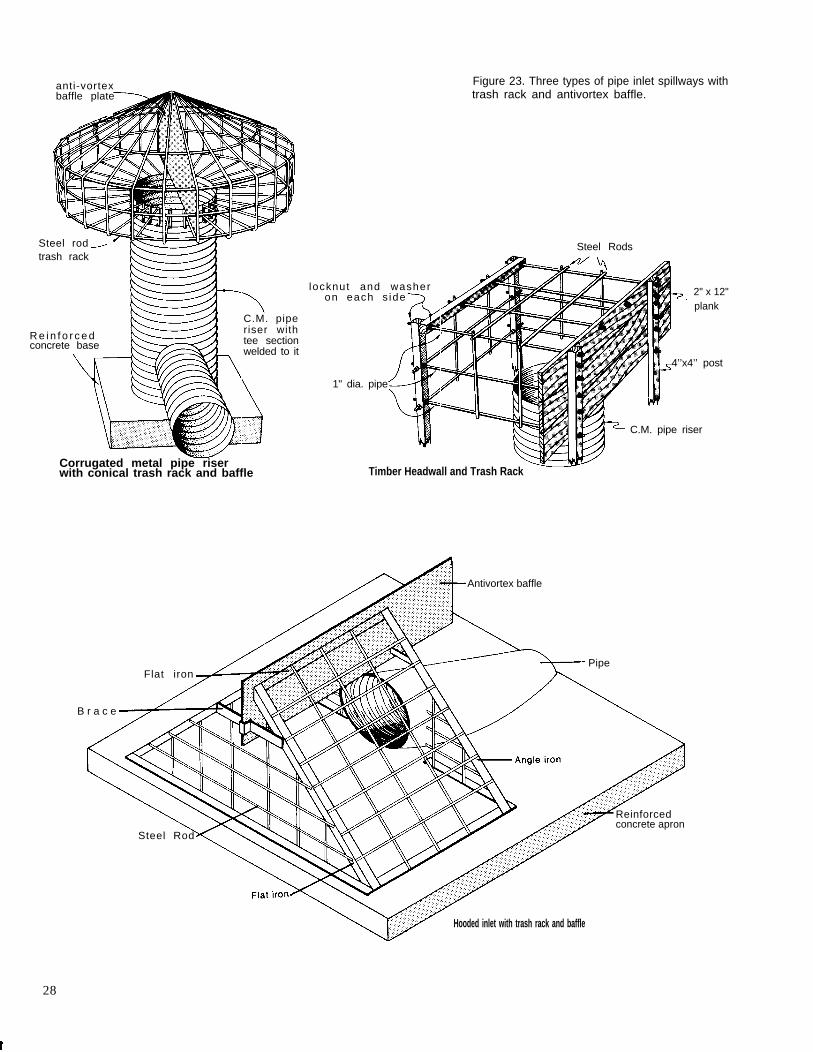
anti-vortexbaffle plate
Figure 23. Three types of pipe inlet spillways withtrash rack and antivortex baffle.
Steel rodtrash rack
Steel Rods
locknut and washeron each s ide
plank2" x 12"
R e i n f o r c e dconcrete base
C.M. piperiser withtee sectionwelded to it
4’’x4’’ post
1" dia. pipe
C.M. pipe riser
Corrugated metal pipe riserwith conical trash rack and baffle Timber Headwall and Trash Rack
Antivortex baffle
PipeFlat iron
B r a c e
Reinforcedconcrete apron
Steel Rod
Hooded inlet with trash rack and baffle
28

Extend pipe above water levelto show location of intake
Bell tile around valve andpipe for suitable housing
Riser with1/4" holes
Corrugated metal pipewith 1" holes. Pipefilled with coarse gravel
Valve
Trough
P o n d
6" concrete base Core fill Union Cap connectionmay be usedfor other purposes
Antiseep collar Control valve
Figure 24. Water is piped through the dam’s drainpipe to a stockwatertrough.
Water impounded on bedrock foundationsseldom gives cause for concern unless the rock con-tains seams, fissures, or crevices through whichwater may escape at an excessive rate. Where rockis found in the foundation, investigate the nature ofthe rock very carefully.
Cutoffs. If the dam’s foundation is overlain byalluvial deposits of pervious sands and gravels at ornear the surface and rock or clay at a greaterdepth, seepage in the pervious stratum must bereduced to prevent possible failure of the dam bypiping. To prevent excessive seepage you need acutoff to join the impervious stratum in the founda-
Figure 25. Cutting a core trench on the centerline of ad a m .
tion with the base of the dam.The most common kind of cutoff is made of
compacted clayey material. A trench is cut alongthe centerline of the dam deep enough to extendwell into the impervious layer (fig. 25). This trenchextends into and up the abutments of the dam asfar as there is any pervious material that mightallow seepage. The bottom of the trench should beno less than 8 feet wide and the sides no steeperthan 1:1. Fill the trench with successive thin layersof clay or sandy clay material. Compact each layerthoroughly at near-optimum moisture conditionsbefore placing the next layer.
Top Width and Alignment. For dams less than10 feet high, a conservative minimum top width is 6feet. As the height of the dam increases, increasethe top width. The recommended minimum top widthfor earth embankments of various heights is:
Height of dam Minimum topwidth
(feet) (feet)
Under 10 . . . . . . . . . . . . . . . . 611 to 14 . . . . . . . . . . . . . . . . . 815 to 19 . . . . . . . . . . . . . . . . . 1020 to 24 . . . . . . . . . . . . . . . . . 1225 to 34 . . . . . . . . . . . . . . . . . 14
If the top of the embankment is to be used for aroadway, provide for a shoulder on each side of theroadway to prevent raveling. The top width shouldbe at least 16 feet. In some situations a curved damalignment is more desirable than a straight align-ment. Curvature can be used to retain existing land-scape elements, reduce the apparent size of thedam, blend the dam into surrounding natural land-forms, and provide a natural-appearing shoreline.
29

Side Slopes. The side slopes of a dam dependprimarily on the stability of the fill and on thestrength and stability of the foundation material.The more stable the fill, the steeper the side slopes.Unstable materials require flatter side slopes. Rec-ommended slopes for the upstream and downstreamfaces of dams built of various materials are shownin table 13.
For stability, the slopes should not be steeperthan those shown in table 13 but they can be flatteras long as they provide surface drainage. The sideslopes need not be uniform but can be shaped toblend with the surrounding landforms (fig. 26).
Finish-grading techniques used to achieve asmooth landform transition include slope roundingat the top and bottom of cuts or fills and on sideslope intersections, and slope warping to createvariety in the horizontal and vertical pitch of fin-ished slopes (fig. 27). Additional fill can be placedon the backslope and abutments of the dam, ifneeded, to achieve this landform transition.
Freeboard. Freeboard is the additional heightof the dam provided as a safety factor to preventovertopping by wave action or other causes. It isthe vertical distance between the elevation of thewater surface in the pond when the spillway is dis-charging at designed depth and the elevation of thetop of the dam after all settlement. If your pond isless than 660 feet long, provide a freeboard of noless than 1 foot. For ponds between 660 and 1,320feet long, the minimum freeboard is 1.5 feet. Forponds up to one-half mile long, the minimum free-board is 2 feet; for longer ponds an engineer shoulddetermine the freeboard.
Settlement Allowance. Settlement or consolida-tion depends on the character of the materials in
both the dam and the foundation and on the con-struction method. To allow for settlement, buildearth dams somewhat higher than the design dimen-sions. If your dam is adequately rolled in thin layersunder good moisture conditions, there is no reasonto expect any appreciable settlement in the dam it-self but the foundation may settle. For a rolled-filldam on unyielding foundation, settlement is neglible.
Most foundations are yielding, and settlementmay range from 1 to 6 percent of the height of thedam, mainly during construction.
The settlement allowance for a rolled-fill damshould be about 5 percent of the designed damheight. In other words, the dam is built 5 percenthigher than the designed height. After settlement,the height of the dam will be adequate.
Most pond dams less than 20 feet high, how-ever, are not rolled fill. For these dams the total set-tlement allowance should be about 10 percent.
Estimating the Volume of the Earthfill. Afterplanning is completed, estimate the number of cubicyards of earth excavation required to build thedam. This helps estimate the cost of the dam andserves as a basis for inviting bids and for awardinga contract.
Table 13.—Recommended side slopes for earthdams
Slope
Fill material Upstream Downstream
Clayey sand, clayey gravel, sandyclay, si l ty sand, si l ty gravel. 3:1 2:1
Silty clay, clayey silt, . . . . . . . . . . . . 3:1 3:1
Figure 26. Dam sideslopes are curved andshaped to blend withsurroundingtopography.
30

The estimate of the volume of excavationshould include the volume in the dam itself includ-ing the allowance for settlement, the volume re-quired to backfill the cutoff trench, the volume re-quired to backfill stream channels or holes in thefoundation area, and any other volume of earth thecontractor is required to remove.
Volume estimates for dams are usually made ofthe required number of cubic yards of earthfill inplace. Probably the most efficient method of estimat-ing the volume of earthfill is the sum-of-end-areamethod. The ground surface elevations at all pointsalong the centerline of the dam where the slopechanges significantly are established by the center-line profile. With the settled top elevation of thedam established, you can obtain the settle fill heightat each of these points by subtracting the groundsurface elevation from the settle top elevation. Withthe fill heights, side slopes, and top width estab-lished, find the end areas at each of these pointsalong the centerline in table 14 (pp. 32 and 33).
For example, assume that a dam has slopes of3:1 on both upstream and downstream sides and atop width of 12 feet. For a point along the centerlinewhere the fill is 15 feet high, the table shows thatthe end area at that point is 675 plus 180, or 855square feet. The number of cubic yards of fill be-tween two points on the centerline of the dam isequal to the sum of the end areas at those twopoints multiplied by the distance between thesepoints and divided by 54. The total volume of earth-fill in the dam is the sum of all such segments. Asample volume estimate illustrating the use of thesum-of-end-areas method is shown in table 15 (p. 34).
The sample volume estimate of 7,732 cubicyards includes only the volume of earth required tocomplete the dam itself. Estimate the volume ofearth required to backfill the core trench, oldstream channels, and other required excavation and
Figure 27. Finish- This
add it to the estimate for the dam. Also include anestimate of additional fill to be placed on the backslope and abutments. For example, assume that, inaddition to the volume shown in table 15, there is acutoff trench to be backfilled. The dimensions of thetrench are:
Average depth = 4.0 ft
Bottom width = 8.0 ft
Side slopes = 1:1
Length = 177 ft
Compute the volume of backfill as follows:
End area = (8 x 4) + (4 x 4) = 48 ft2
Volume =48 X 177
= 315 yd3
27
Add this to the volume required for the damand the total volume is 7,732 plus 315 or 8,047cubic yards.
Plans and Specifications. Record all planninginformation on an engineering plan. This planshould show all elevations and dimensions of thedam, the dimensions and extent of the cutoff trenchand other areas requiring backfill, the location anddimensions of the trickle tube and other planned ap-purtenances, and any other pertinent information.The plan should also include a list of the quantityand kind of building materials required.
Unless you have all the necessary equipment,you will need to employ a contractor to build thepond. You may wish to receive bids from several
Thisgrading techniques.
Slope rounding Slope warping
Not this Not this
31
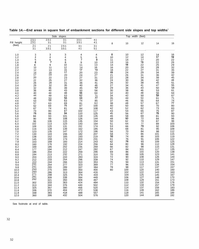
Table 14.—End areas in square feet of embankment sections for different side slopes and top widths1
Side slopes Top width (feet)2.5:1
Fill height 2.5:1(feet) 2:1
3:1
1.01.21.41.61.82.02.2
5
2.42.62.83.03.23.4
1720
19
3.63.84.04.24.44.64.85.05.2
58
5.45.65.86.06.26.46.66.87.07.27.47.67.88.08.28.48.68.89.09.29.49.69.8
10.010.210.410.6
23124125026027128129210.8
11.011.211.411.611.812.0
34
8101214
22262932364044485357626773
849096
102109116123130138145153160169177186194203212222
302313325336348360
2.5:1 3:13:1 3:12:1 2.5:1
3.5:1 3.5:1
345
9111316
222528323640444953
63697480869399
106113120128135143152159168176185194204213223233244254265275286298309321333344357370383396
3468
101215
202327313539434853
6369
8187
101108115123131139147156165174183192202212222232243254266277289300313325338350363376390404418432
3.5:13.5:1
3:14:1
4:14:1 8 103:15:1
45
91114
2024273236404550
6874818794
102110118126135143152162172182193203214224235247259271283296310323337350364379394409424440456472488504
46
101316
232731364146
586471
859 2
100108117125135144154164174185196207219231243256269282296310324339353369384400416433449467484502520538557576
101113141618
212224262729303234353738404243454648505153545658
61626466676970727475777880
10121416
2022242628303234363840424446485052545658
6264666870727476
80828486889092949698
100102104106108110112114116118120
12 14 16
121417
222427293134363841434648505355576062656769727477
8184868991939698
101103105108110113115117120122125127129132134137139141144
14
2022252831343639424547505356
616467707375
81848789929598
101103106109112115117120123126129131134137140143145148151154157159162165168
16
2226293235394245485155586164677174
80838790939699
103106109112115119122125128131135138141144147151154157160163167170173176179183186189192
See footnote at end of table.
32
32

Table 14.—End areas in square feet of embankment sections for different side slopes and topwidths 1 —Continued
Side slopes Top width (feet)2.5:1 2.5:1 3:1 3.5:1 4:1
Fill height 2.5:1 3:1 3:1 3.5:1(feet) 2:1 2:1 2.5:1 3:1
3:1 3.5:1 3.5:1
4:1 8 10 123:15:1
14 16
195199202205208211215218221224227230234237240243246250253256259262266269272275278282285288291294298301304307310314317320323326330333336339342346349352355358362365368
4:1
12.212.412.612.813.0
372385397
409424437451
447462477492507523539555571588605
522539557574592610629648667686706726746767788809830852874896919942965988
1,0121,0361,0601,0841,1091,1341,1601,1861,2121,2381,2641,2911,3181,3451,3721,4001,4281,4571,4861,5151,5441,5741,6041,6341,6641,6941,7251,7561,7881,8201,852
595615635655676697718740762784
122124126128130132134136138
146149151
171173176179182185187190193196199202204207210213216218221224227230232235238241244246249252255258260263266269272274277280283286288291294297300302305308311314316319322
410422436449463476490505519
153156158161163166
46513.213.413.613.814.014.214.4
479494509523539555570
140142144146148150152
168170807
829853876900924949
622639657675693711730
173175178180182
14.614.8
534548563578594609625
586602619635653669687
15.015.215.415.615.8
154 185187190192194197199202204
973999
156749768787807827847867888
15816016.0
16.216.416.616.817.017.217.4
640656673689706723740757
704722740758776795814833
1,0241,0501,0761,1021,1291,1561,183 206
209211214216
909930951972994
1,0161,038
1,2111,2391,2671,2961,3251,354
17.6 774792810828846865
852871891911931951972993
1,0141,0351,0561,0781,1001,1221,1441,1671,1901,2131,2361,2541,2831,3071,3311,3561,3801,4051,430
17.818.018.218.418.6
218221
1,3841,4141,4441,4751,5051,5371,568
223226228230233235
18.819.019.219.419.619.820.020.220.420.620.821.021.221.421.6
884903922941960980
1,0001,020
1,0601,0831,1061,1291,1521,1761,200
238240242245247250
1,6001,2241,2481,2731,2981,3231,3481,374
1,6321,6651,6971,7311,7641,798
1,0401,0611,0821,1031,1241,145
252254257259262264266269
1,8321,8661,9011,9361,9712,0072,043
1,1661,1881,2101,2321,2541,2771,300
1,4001,4261,4521,4791,5061,5331,560
21.822.022.222.422.622.823.0
271274276
2,0792,1161,323 1,455 1,587
1To find the end area for any fill height, add square feet given under staked side slopes to that under the top width for total sec-tion. Example: 6.4-foot fill 3:1 front and back slopes, 14-foot top width—123 plus 89 or 212 square feet for the section. Any com-bination of slopes that adds to 5, 6, or 7 may be used. A combination of 3.5:1 front and 2.5:1 back gives the same results as 3:1front and back
33

Table 15.–Volume of earth needed for the earthfill
Ground Fill Sum of DoubleStation elevation height 1 End area2 end areas Distance
ft
0 + 5 0
+ 68
1 + 00
+ 37
+ 53
+ 75
2 + 00
+ 19
+ 32
+ 36
+ 40
+ 43
+ 46
+ 59
3 + 00
+ 35
+ 60
3 + 96
ft
35.0
32.7
25.9
21.5
20.0
19.8
19.5
20.3
20.3
18.8
18.2
18.5
19.6
19.8
20.8
27.7
31.6
35.0
ft
0
2.3
9.1
13.5
15.0
15.2
15.5
14.7
14.7
16.2
16.8
16.5
15.4
15.2
14.2
7.3
3.4
.0
Sq. ft. Sq. ft.
4 444-
401357-
1,066709-
1,564855-
1,730875-
1,781906-
1,730824-
1,648824-
1,805981-
2,0301,049-
2,0641,015-
1,911896-
1,771875-
1,650775-
1,023248-
32476-
7 60-
ft
18
32
37
16
22
25
19
13
4
4
3
3
13
41
35
25
36
Total
volume
cu. ft.
792
12,832
39,442
25,024
38,060
44,525
32,870
21,424
7,220
8,120
6,192
5,733
23,023
67,650
35,805
8,100
2,736
3379,548
1Elevation of top of dam without allowance for settlement.2End areas based on 12-foot top width and 3:1 slopes on both sides.
3Divide double volume in cubic feet by 54 to obtain volume in cubic yards, e.g. 7,029 cubic yards
Allowance for settlement (10%) = 703 cubic yardsTotal volume = 7,732 cubic yards
contractors to be sure that you are getting the jobdone at the lowest possible cost. If so, you need toprepare a plan and a set of specifications showingwhat is to be done. This provides a basis for con-tractors to bid on the proposed work, allows faircompetition among bidders, and states the condi-tions under which the work is to be done.
The specifications should give all the informa-tion not shown on the plans that is necessary todefine what is to be done, prescribe how the workis to be done if such direction is required, specifythe quality of material and workmanship required,and define the method of measurement and the unitof payment for the various items of work that con-stitute the whole job. Construction work of the
quality and standards desired will not result unlessthere is a clear understanding of these require-ments between the owner and the contractor. Forthese reasons specifications should be prepared forall ponds for which the owners award the contracts.
Assistance in preparing plans and specifica-tions is available from your local soil conservationdistrict, SCS specialists, or private consultants.
Staking for Construction
Each job must be adequately and clearly stakedbefore construction is started. Staking transmits theinformation on the plan to the job site. This informa-tion locates the work and provides the lines, grade,
34

and elevations required for construction in accor-dance with the plan. Consider the contractor’swishes in staking so that he can make the most ef-fective use of the stakes. The quality and appear-ance of the completed job reflects the care used instaking. Unless you are familiar with the use ofsurveyor’s instruments, the staking should be doneby an engineer or other qualified person.
The areas to be cleared generally consist of thedam site, the spillway site, the borrow area, and thearea over which water is to be impounded. Markeach area clearly with an adequate number ofstakes. In the pond area, locate the proposed water-line with a level and rod. This provides a base linefrom which clearing limits can be established.
To locate the dam, set stakes along its center-line at intervals of 100 feet or less. Usually thishas been done during the initial planning survey.Then set the fill and slope stakes upstream anddownstream from the centerline stakes to mark thepoints of intersection of the side slopes with theground surface and to mark the outer limits of con-struction. These stakes also establish the height ofthe dam.
To locate the earth spillway, first stake thecenterline and then set cut and slope stakes alongthe lines of intersection of the spillway side slopeswith the natural ground surface.
If fill material must be obtained from a borrowarea, this area must be clearly marked. Set cutstakes to indicate the depth to which the contractorcan excavate to stay within the limits of suitablematerial, as indicated by soil borings. This willallow the borrow area to drain readily and willmark the limits of construction activity.
Set stakes to show the centerline location of thetrickle spillway after foundation preparation hasreached the point at which the stakes will not bedisturbed. Locate the trickle tube where it will reston a firm foundation. Mark the stakes to show cutsfrom the tops of the stakes to the grade elevation ofthe tube. With additional stakes, mark the locationof the riser, drainage gate, antiseep collars, outletstructures, and other appurtenances.
Building the Pond
Attention to the details of construction and ad-herence to specifications are as important as ade-quate investigation and design. Careless and shoddyconstruction can make an entirely safe and ade-quate design worthless and cause failure of thedam. Adherence to specifications and prescribedconstruction methods becomes increasingly impor-tant as the size of the structure and the failurehazards increase. Good construction is important
regardless of size and the cost is generally less inthe long run than it is for dams built carelessly.
Clearing and Grubbing. Clear the foundationarea and excavated spillway site of trees andbrush. In some states this is required by statute. Cuttrees and brush as nearly flush with the ground aspracticable and remove them and any other debrisfrom the pond site. Should you or your contractorelect to uproot the trees with a bulldozer, you mustdetermine if the tree roots extend into perviousmaterial and if the resultant holes will cause exces-sive seepage. If so, fill the holes by placing suitablematerial in layers and compact each layer by roll-ing or tamping.
All material cleared and grubbed from thepond site, from the spillway and borrow areas, andfrom the site of the dam itself should be disposed of.This can be done by burning, burying under 2 feetof soil, or burying in a disposal area such as asanitary landfill.
Minimal clearing should be done to conservethe visual quality of the site and to minimize the dif-ficulty and expense of reestablishing vegetation.Confine clearing limits to the immediate construc-tion area to avoid unnecessary disturbance. Largetrees near the top of cut slopes may have to be re-moved to avoid excessive root damage.
It is not always necessary to remove all vegeta-tion within the construction limits. Selected groupings of desirable plants can be kept. Trees andshrubs can often survive a 1- to 2-foot layer ofgraded fill over their root systems or they can beroot-pruned in excavated areas. Tree wells andraised beds can also be used to retain vegetation(fig. 28).
Clearing limits should be irregular to provide anatural-appearing edge and open area (fig. 29,p. 36), Further transition with vegetated surround-ings can be accomplished by feathering clearing
Figure 28. A tree well preserves vegeta-tion.
35

edges. Density and height of vegetation can be in-creased progressively from the water’s edge to theundisturbed vegetation (fig. 30). In this way thecleared area will look more natural. Feathering canbe accomplished by selective clearing, installationof new plants, or both.
Preparing the Foundation. Preparing the foun-dation usually includes treating the surface, exca-vating and backfilling the cutoff trench, and exca-vating and backfilling existing stream channels. Ifthe foundation contains an adequate layer of imper-vious material at the surface or if it must be blan-keted by such a layer, you can eliminate the cutofftrench. Remove sod, boulders, and topsoil from theentire area over which the embankment is to beplaced. This operation is best performed by using atractor-pulled wheeled scraper. The topsoil shouldbe stockpiled temporarily for later use on the site.
Fill all holes in the foundation area, bothnatural and those resulting from grubbing opera-tions, with suitable fill material from borrow areas.Use the same method of placement and compactionas used to build the dam. Where necessary usehand or power tampers in areas not readily acces-sible to other compacting equipment.
After filling the holes, thoroughly break theground surface and turn it to a depth of 6 inches.Roughly level the surface with a disk harrow andthen compact it so that the surface materials of thefoundation are as well compacted as the subsequentlayers of the fill (fig. 31).
Dig the cutoff trench to the depth, bottomwidth, and side slopes shown on the plans. Oftenthe depths shown on the plans are only approx-imate; you need to inspect the completed trenchbefore backfilling to be sure that it is excavated atleast 12 inches into impervious material throughoutits entire length.
The material removed from the trench that isfree of boulders, roots, organic matter, and otherobjectionable material can be placed in the down-stream one-third of the dam and compacted in thesame manner as the earthfill.
A dragline excavator and a tractor-pulledwheeled scraper are the most satisfactory equip-ment for excavating cutoff trenches.
Before backfilling operations are attempted,pump all water from the cutoff trench. Some mate-rial high in clay content takes up more than twiceits own weight of water and becomes a soggy mass.Such clay puddled in the cutoff of a dam may re-quire many years to become stable. Also, in dryingit contracts and may leave cracks that can producea roof of the overlying impervious earthfill section
and provide passageways for seepage through thedam.
Backfill the cutoff trench to the natural groundsurface with suitable fill material from designatedborrow areas. Place the backfill material in thinlayers and compact it by the same methods used tobuild the dam.
If stream channels cross the embankment foun-dation, deepen and widen them as necessary toremove all stones, gravel, sand, sediment, stumps,roots, organic matter, and any other objectionablematerial that could interfere with proper bonding ofthe earthfill with the foundation. Leave side slopesof the excavated channels no steeper than 1:1.Backfill these channels as recommended for the cut-off trench.
Installing the Trickle Tube. Build the trickletube, riser, antiseep collars, trash rack, and othermechanical components of the dam to the lines andgrades shown on the plans and staked on the site.To minimize the danger of cracks or openings at thejoints caused by unequal settlement of the founda-tion, place all trickle tube barrels and other con-duits on a firm foundation.
ThisExisting trees
Irregular clearing edge
Not this
Straight clearing edge
Pond
Figure 29. Irregular clearing around thepond helps create a natural-appearingedge.
36

Not thisThisSelective clearingand/or plantings
TExisting trees
.
Minimumclearinglimits
Existing trees
Clearing limits
Selective clearing and/or planting Lack of transition treatment
P o n d
creates a natural appearance
Figure 30. Feathering vegetation at the pond’s edgemakes a natural transition with existing vegetation.
Install barrels and antiseep collars and tampthe selected backfill material around the entiretrickle tube structure before placing the earthfill forthe dam. The same procedure applies to all otherpipes or conduits.
Excavating the Earth Spillway. The completedspillway excavation should conform as closely aspossible to the lines, grades, bottom width, and sideslopes shown on the plans and staked on the site.Leave the channel bottom transversely level to pre-vent meandering and the resultant scour within thechannel during periods of low flow. If it becomesnecessary to fill low places or depressions in thechannel bottom caused by undercutting the estab-lished grade, fill them to the established grade byplacing suitable material in 8-inch layers and com-pacting each layer under good moisture conditions.
Building the Dam. Clear the dam and spillwayarea of trees, brush, stumps, boulders, sod, and rub-bish. The sod and topsoil can be stockpiled andused later to cover the dam and spillway (fig. 32p. 38). This will help when vegetation is established.Get suitable fill material from previously selectedborrow areas and from sites of planned excavation.The material should be free of sod, roots, stonesmore than 6 inches in diameter, and any materialthat could prevent the desired degree of compac-tion. Do not use frozen material or place fill mate-rial on frozen foundations.
Selected backfill material should be placed inthe core trench and around pipes and antiseep col-lars. The material should be compacted by handtamping or manually directed power tampers. Beginplacing fill material at the lowest point and bring itup in horizontal layers approximately 8 inchesthick. Do not place fill in standing water. If thematerial can be formed into a firm ball that sticks
creates an unnatural edge
together, the moisture content is adequate for com-paction. Laboratory tests of the fill material andfield testing of the soil for moisture and compactionmay be necessary for large ponds or special condi-tions.
If the material varies in texture and gradation,use the more impervious (clay) material in the coretrench, center, and upstream parts of the dam.
Construction equipment can be used to pack fillin an ordinary pond. Equipment with rubber tirescan be routed so each layer is covered by a tiretrack. For dams over 20 feet high, special equip-ment such as sheepsfoot rollers should be used.
Excavated Ponds
Excavated ponds are the simplest to build inrelatively flat terrain. Because their capacity is ob-tained almost solely by excavation, their practicalsize is limited. They are best suited to locations
Figure 31. A pond in early stages of con-struction.
37
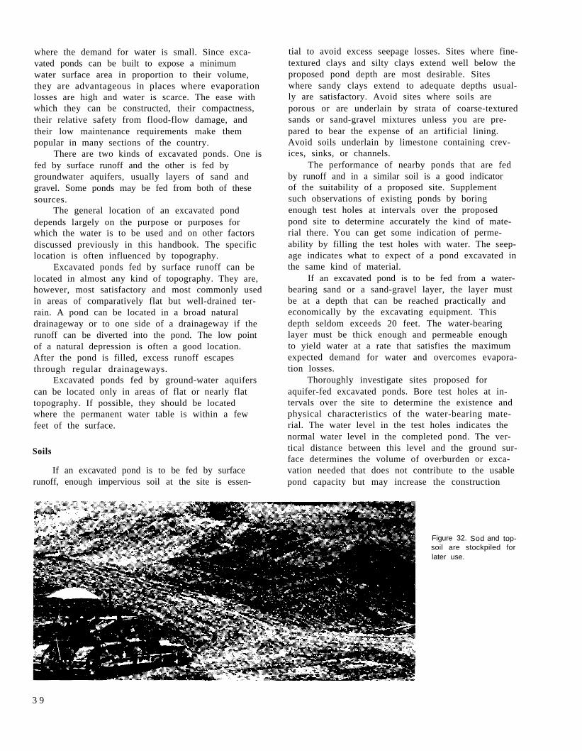
where the demand for water is small. Since exca-vated ponds can be built to expose a minimumwater surface area in proportion to their volume,they are advantageous in places where evaporationlosses are high and water is scarce. The ease withwhich they can be constructed, their compactness,their relative safety from flood-flow damage, andtheir low maintenance requirements make thempopular in many sections of the country.
There are two kinds of excavated ponds. One isfed by surface runoff and the other is fed bygroundwater aquifers, usually layers of sand andgravel. Some ponds may be fed from both of thesesources.
The general location of an excavated ponddepends largely on the purpose or purposes forwhich the water is to be used and on other factorsdiscussed previously in this handbook. The specificlocation is often influenced by topography.
Excavated ponds fed by surface runoff can belocated in almost any kind of topography. They are,however, most satisfactory and most commonly usedin areas of comparatively flat but well-drained ter-rain. A pond can be located in a broad naturaldrainageway or to one side of a drainageway if therunoff can be diverted into the pond. The low pointof a natural depression is often a good location.After the pond is filled, excess runoff escapesthrough regular drainageways.
Excavated ponds fed by ground-water aquiferscan be located only in areas of flat or nearly flattopography. If possible, they should be locatedwhere the permanent water table is within a fewfeet of the surface.
Soils
If an excavated pond is to be fed by surfacerunoff, enough impervious soil at the site is essen-
tial to avoid excess seepage losses. Sites where fine-textured clays and silty clays extend well below theproposed pond depth are most desirable. Siteswhere sandy clays extend to adequate depths usual-ly are satisfactory. Avoid sites where soils areporous or are underlain by strata of coarse-texturedsands or sand-gravel mixtures unless you are pre-pared to bear the expense of an artificial lining.Avoid soils underlain by limestone containing crev-ices, sinks, or channels.
The performance of nearby ponds that are fedby runoff and in a similar soil is a good indicatorof the suitability of a proposed site. Supplementsuch observations of existing ponds by boringenough test holes at intervals over the proposedpond site to determine accurately the kind of mate-rial there. You can get some indication of perme-ability by filling the test holes with water. The seep-age indicates what to expect of a pond excavated inthe same kind of material.
If an excavated pond is to be fed from a water-bearing sand or a sand-gravel layer, the layer mustbe at a depth that can be reached practically andeconomically by the excavating equipment. Thisdepth seldom exceeds 20 feet. The water-bearinglayer must be thick enough and permeable enoughto yield water at a rate that satisfies the maximumexpected demand for water and overcomes evapora-tion losses.
Thoroughly investigate sites proposed foraquifer-fed excavated ponds. Bore test holes at in-tervals over the site to determine the existence andphysical characteristics of the water-bearing mate-rial. The water level in the test holes indicates thenormal water level in the completed pond. The ver-tical distance between this level and the ground sur-face determines the volume of overburden or exca-vation needed that does not contribute to the usablepond capacity but may increase the construction
soil are stockpiled forFigure 32.
later use.
Sod and top-
3 9

cost considerably. From an economic standpoint,this vertical distance between water level andground surface generally should not exceed 6 feet.
Check the rate at which the water rises in thetest holes. A rapid rate of rise indicates a high-yielding aquifer. If water is removed from the pondat a rapid rate, as for irrigation, the water can beexpected to return to its normal level within a shorttime after removal has ceased. A slow rate of risein the test holes indicates a low-yielding aquifer anda slow rate of recovery in the pond. Check the testhole during drier seasons of the year to avoid beingmisled by a high water table that is only temporary.
Spillway and Inlet Requirements
If you locate an excavated pond fed by surfacerunoff on sloping terrain, you can use a part of theexcavated material for a small low dam around thelower end and sides of the pond to increase itscapacity. You need an earth spillway to pass ex-cess storm runoff around the small dam. Follow theprocedures for planning the spillway and provideprotection against erosion as discussed on page 37.
Ponds excavated in areas of flat terrain usuallyrequire prepared spillways. If surface runoff mustenter an excavated pond through a channel or ditchrather than through a broad shallow drainageway,the overfall from the ditch bottom to the bottom ofthe pond can create a serious erosion problemunless the ditch is protected. Scouring can occur inthe side slope of the pond and for a considerabledistance upstream in the ditch. The resulting sedi-ment tends to reduce the depth and capacity of thepond. Protect by placing one or more lengths ofrigid pipe in the ditch and extend them over theside slope of the excavation. The extended part ofthe pipe or pipes can be either cantilevered or sup-ported with timbers. The diameter of the pipe orpipes depends on the peak rate of runoff that canbe expected from a 10-year frequency storm. If youneed more than one pipe inlet, the combined capac-ity should equal or exceed the estimated peak rateof runoff.
Figure 33. A pond may be excavated in ageometric form, then graded to create amore natural configuration.
Pipe diameter1 Pond inflow Q(inches) (ft3/sec)
15 . . . . . . . . . . . . . . . . . . . . . . . . . . 0 to 618 . . . . . . . . . . . . . . . . . . . . . . . . . . 6 to 921 . . . . . . . . . . . . . . . . . . . . . . . . . . 9 to 1324 . . . . . . . . . . . . . . . . . . . . . . . . . . 13 to 1830 . . . . . . . . . . . . . . . . . . . . . . . . . . 18 to 3036 . . . . . . . . . . . . . . . . . . . . . . . . . . 30 to 4642 . . . . . . . . . . . . . . . . . . . . . . . . . . 46 to 6748 . . . . . . . . . . . . . . . . . . . . . . . . . . 67 to 9254 . . . . . . . . . . . . . . . . . . . . . . . . . . 92 to 12260 . . . . . . . . . . . . . . . . . . . . . . . . . . 122 to 1581Based on a free outlet and a minimum pipe slope of 1.0percent with the water level 0.5 foot above the top of thepipe at the upstream end.
In areas where a considerable amount of silt iscarried by the in flowing water, you should providea desilting area or filter strip in the drainagewayimmediately above the pond to remove the siltbefore it enters the pond. This area or strip shouldbe as wide as or somewhat wider than the pond and100 feet or more long. After you prepare a seedbed,fertilize and seed the area to adapted perennialgrasses. As the water flows through the grass, thesilt settles out and the water entering the pond isrelatively silt free.
Planning the Pond
Although excavated ponds can be built toalmost any shape desired, a rectangle is commonlyused in relatively flat terrain. The rectangularshape is popular because it is simple to build andcan be adapted to all kinds of excavating equip-ment.
The rectangular shape should not be used, how-ever, where the resulting straight lines would be insharp contrast to surrounding landscape patterns.A pond can be excavated in a rectangular form andthe edge shaped later with a blade scraper tocreate an irregular configuration (fig. 33).
The capacity of an excavated pond fed by sur-face runoff is determined largely by the purpose orpurposes for which water is needed and by theamount of inflow that can be expected in a givenperiod. The required capacity of an excavated pondfed by an underground water-bearing layer is diffi-cult to determine because the rate of inflow into thepond can seldom be estimated accurately. For thisreason, the pond should be built so that it can beenlarged if the original capacity proves inadequate.
Selecting the Dimensions. The dimensionsselected for an excavated pond depend on the re-quired capacity. Of the three dimensions of a pond,the most important is depth. All excavated ponds
39
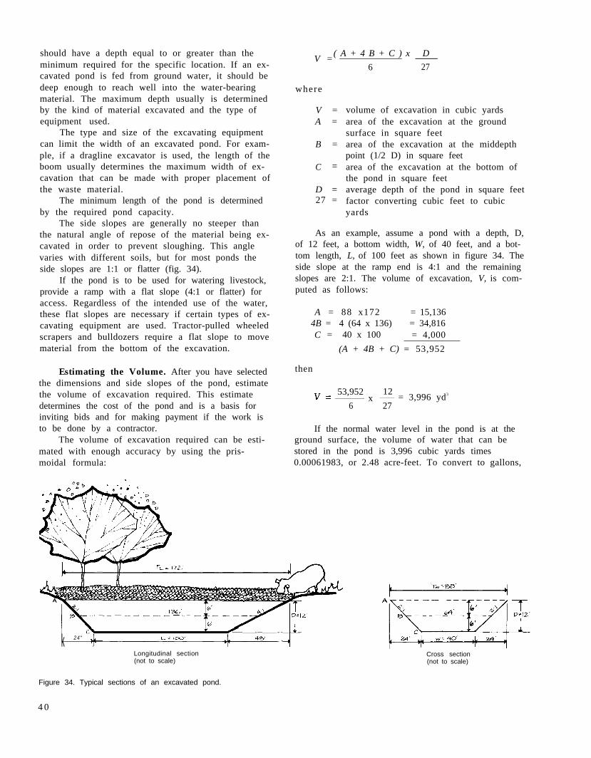
should have a depth equal to or greater than theminimum required for the specific location. If an ex-cavated pond is fed from ground water, it should bedeep enough to reach well into the water-bearingmaterial. The maximum depth usually is determinedby the kind of material excavated and the type ofequipment used.
The type and size of the excavating equipmentcan limit the width of an excavated pond. For exam-ple, if a dragline excavator is used, the length of theboom usually determines the maximum width of ex-cavation that can be made with proper placement ofthe waste material.
The minimum length of the pond is determinedby the required pond capacity.
The side slopes are generally no steeper thanthe natural angle of repose of the material being ex-cavated in order to prevent sloughing. This anglevaries with different soils, but for most ponds theside slopes are 1:1 or flatter (fig. 34).
If the pond is to be used for watering livestock,provide a ramp with a flat slope (4:1 or flatter) foraccess. Regardless of the intended use of the water,these flat slopes are necessary if certain types of ex-cavating equipment are used. Tractor-pulled wheeledscrapers and bulldozers require a flat slope to movematerial from the bottom of the excavation.
V =
Estimating the Volume. After you have selectedthe dimensions and side slopes of the pond, estimatethe volume of excavation required. This estimatedetermines the cost of the pond and is a basis forinviting bids and for making payment if the work isto be done by a contractor.
The volume of excavation required can be esti-mated with enough accuracy by using the pris-moidal formula:
( A + 4 B + C ) x D
6 27
where
V =A =
B =
C =
D =27 =
volume of excavation in cubic yardsarea of the excavation at the groundsurface in square feetarea of the excavation at the middepthpoint (1/2 D) in square feetarea of the excavation at the bottom ofthe pond in square feetaverage depth of the pond in square feetfactor converting cubic feet to cubicyards
As an example, assume a pond with a depth, D,of 12 feet, a bottom width, W, of 40 feet, and a bot-tom length, L, of 100 feet as shown in figure 34. Theside slope at the ramp end is 4:1 and the remainingslopes are 2:1. The volume of excavation, V, is com-puted as follows:
A = 88 x172 = 15,1364B = 4 (64 x 136) = 34,816C = 40 x 100 = 4,000
(A + 4B + C) = 53,952
then
53,952x = 3,996 yd3
6 27
12
If the normal water level in the pond is at theground surface, the volume of water that can bestored in the pond is 3,996 cubic yards times0.00061983, or 2.48 acre-feet. To convert to gallons,
k 24“
Longitudinal section(not to scale)
Figure 34. Typical sections of an excavated pond.
Cross section(not to scale)
4 0
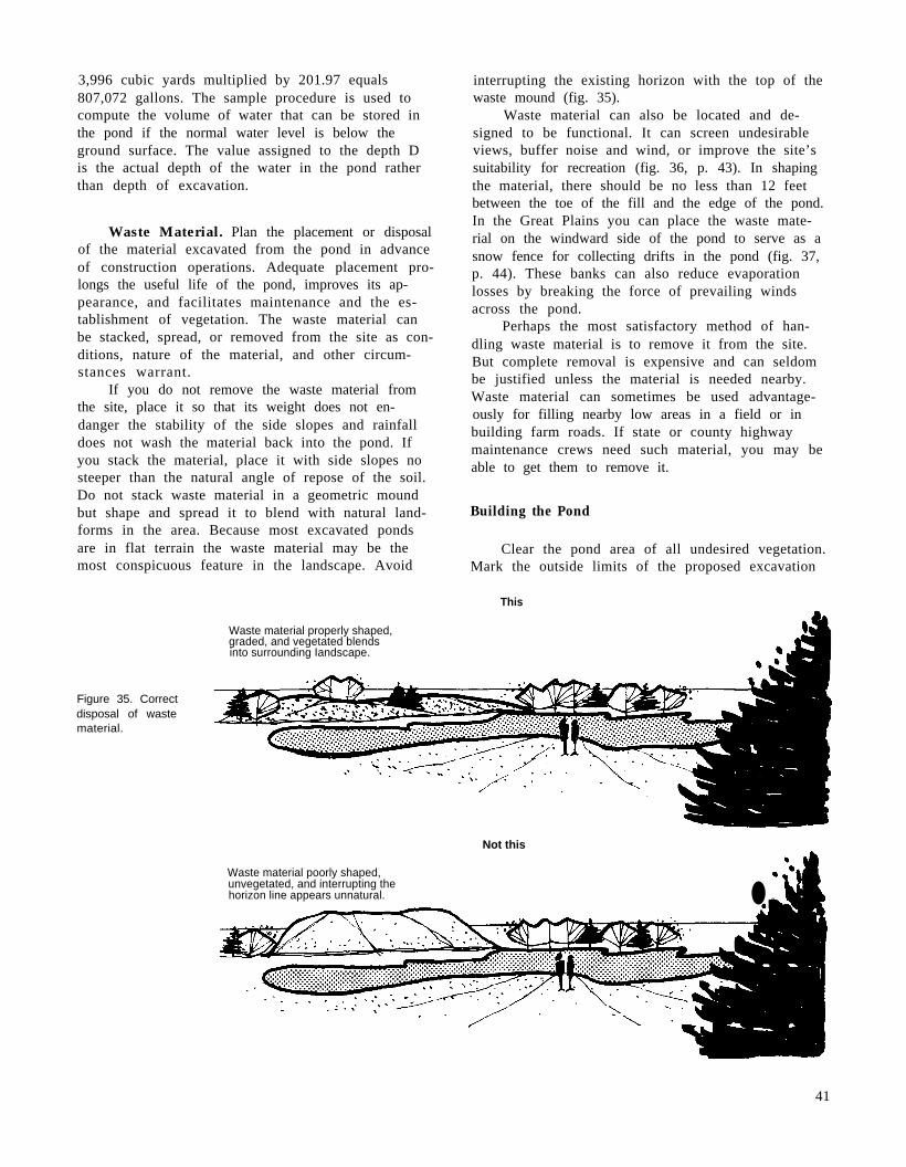
3,996 cubic yards multiplied by 201.97 equals807,072 gallons. The sample procedure is used tocompute the volume of water that can be stored inthe pond if the normal water level is below theground surface. The value assigned to the depth Dis the actual depth of the water in the pond ratherthan depth of excavation.
Waste Material. Plan the placement or disposalof the material excavated from the pond in advanceof construction operations. Adequate placement pro-longs the useful life of the pond, improves its ap-pearance, and facilitates maintenance and the es-tablishment of vegetation. The waste material canbe stacked, spread, or removed from the site as con-ditions, nature of the material, and other circum-stances warrant.
If you do not remove the waste material fromthe site, place it so that its weight does not en-danger the stability of the side slopes and rainfalldoes not wash the material back into the pond. Ifyou stack the material, place it with side slopes nosteeper than the natural angle of repose of the soil.Do not stack waste material in a geometric moundbut shape and spread it to blend with natural land-forms in the area. Because most excavated pondsare in flat terrain the waste material may be themost conspicuous feature in the landscape. Avoid
Waste material properly shaped,graded, and vegetated blendsinto surrounding Iandscape.
interrupting the existing horizon with the top of thewaste mound (fig. 35).
Waste material can also be located and de-signed to be functional. It can screen undesirableviews, buffer noise and wind, or improve the site’ssuitability for recreation (fig. 36, p. 43). In shapingthe material, there should be no less than 12 feetbetween the toe of the fill and the edge of the pond.In the Great Plains you can place the waste mate-rial on the windward side of the pond to serve as asnow fence for collecting drifts in the pond (fig. 37,p. 44). These banks can also reduce evaporationlosses by breaking the force of prevailing windsacross the pond.
Perhaps the most satisfactory method of han-dling waste material is to remove it from the site.But complete removal is expensive and can seldombe justified unless the material is needed nearby.Waste material can sometimes be used advantage-ously for filling nearby low areas in a field or inbuilding farm roads. If state or county highwaymaintenance crews need such material, you may beable to get them to remove it.
Building the Pond
Clear the pond area of all undesired vegetation.Mark the outside limits of the proposed excavation
This
Figure 35. Correctdisposal of wastematerial.
Not this
Waste material poorly shaped,unvegetated, and interrupting thehorizon line appears unnatural. ● ,g-
41

with stakes. On the stakes indicate the depth of cutfrom the ground surface to the pond bottom.
Excavation and placement of the waste mate-rial are the principal items of work in building thistype of pond. The kind of excavating equipment useddepends on the climatic and physical conditions atthe site and on what equipment is available.
In low-rainfall areas where water is unlikely toaccumulate in the excavation, you can use almostany kind of available equipment. Tractor-pulledwheeled scrapers, dragline excavators, and track-type tractors equipped with a bulldozer blade aregenerally used. Bulldozers can only push the ex-cavated material, not carry it; if the length of pushis long, using these machines is expensive.
In high-rainfall areas and in areas where thereis a ground-water table within the limits of excava-tion, a dragline excavator is commonly used becauseit is the only kind of equipment that operates satis-factorily in any appreciable depth of water. Forponds fed by ground-water aquifers, a dragline isnormally used to excavate the basic pond.
Excavate and place the waste material as closeas possible to the lines and grades staked on thesite. If you use a dragline excavator, you usuallyneed other kinds of equipment to stack or spreadthe waste material and shape the edge to an irregu-lar configuration. Bulldozers are most commonlyused. Graders, either tractor-pulled or self-pro-pelled, can be used to good advantage, particularlyif the waste material is to be shaped.
Compaction
Some pond areas can be made relatively imper-vious by compaction alone if the material contains awide range of particle sizes—small gravel or coarsesand to fine sand—and enough clay (usually 10 per-cent or more) and silt to effect a seal. This is theleast expensive method of those presented in thishandbook. Its use, however, is limited to these soilconditions as well as by the depth of water to be im-pounded.
The procedure is simple. Clear the pond area ofall trees and other vegetation. Fill all stump holes,crevices, and similar areas with impervious mate-rial. Scarify the soil to a depth of 8 to 10 incheswith a disk, rototiller, pulverizer, or similar equip-ment. Remove all rocks and tree roots. Roll theloosened soil under optimum moisture conditions toa dense, tight layer with four to six passes of asheepsfoot roller in the same manner as for com-pacting earth embankments.
Make the compacted seal no less than 8 inchesthick where 10 feet or less of water is to be im-pounded. Since seepage losses vary directly withthe depth of water impounded over an area, in-crease the thickness of the compacted seal propor-tionately if the depth of water impounded exceeds10 feet. Compact the soils in two or more layers notexceeding 8 inches over that section of the pondwhere the water depth exceeds 10 feet. Remove andstockpile the top layer or layers while the bottomlayer is being compacted.
Sealing the PondClay Blankets
Excessive seepage in ponds is generally due toa poor site, that is, one where the soils in the im-pounding area are too permeable to hold water. Se-lecting a poor site is often the result of inadequatesite investigations and could have been avoided. Insome places no satisfactory site is available but theneed for water is great enough to justify using a sitethat is somewhat less than satisfactory. If so, theoriginal pond design must include plans for reduc-ing seepage by sealing. In some places excessiveremoval of the soil mantle during construction,usually to provide material for the embankment, ex-poses highly pervious material such as sand, gravel,or rock containing cracks, crevices, or channels.This usually can be avoided by carefully selectingthe source of embankment material.
To prevent excessive seepage, reduce thepermeability of the soils to a point at which lossesare insignificant or at least tolerable. The methoddepends largely on the proportions of coarse-grained sand and gravel and of fine-grained clayand silt in the soil.
Pond areas containing high percentages ofcoarse-grained soils but lacking enough clay to pre-vent excessive seepage can be sealed by blanketing.Blanket the entire area over which water is to beimpounded as well as the upstream slope of the em-bankment. The blanket should consist of a well-graded material containing at least 20 percent clay.The requirements for good blanklet material areabout the same as those described for earth em-bankments. You can usually obtain material for theblanket from a borrow area close enough to thepond to permit hauling at a reasonable cost.
Thickness of the blanket depends on the depthof water to be impounded. The minimum thickness is12 inches for all depths of water up to 10 feet. In-crease this thickness by 2 inches for each foot ofwater over 10 feet.
Construction is similar to that for earth em-bankments. Remove all trees and other vegetationand fill all holes and crevices before hauling earthmaterial from the borrow area to the pond site in
42

tractor-pulled wheeled scrapers or similar equip-ment. Spread the material uniformly over the areain layers 6 to 8 inches thick. Compact each layerthoroughly, under optimum moisture conditions, byfour to six passes of a sheepsfoot roller before plac-ing the next layer.
Protect clay blankets against cracking thatresults from drying and against rupture caused byfreezing and thawing. Spread a cover of gravel 12to 18 inches thick over the blanket below the an-ticipated high water level. Use rock riprap or othersuitable material to protect areas where the water-flow into the pond is concentrated.
Bentonite
Adding bentonite is another method of reducingexcessive seepage in soils containing high percent-ages of coarse-grained particles and not enoughclay. Bentonite is a fine-textured colloidal clay.When wet it absorbs several times its own weightof water and, at complete saturation, swells asmuch as 8 to 20 times its original volume. Mixed inthe correct proportions with well-graded coarse-grained material, thoroughly compacted and thensaturated, the particles of bentonite swell until theyfill the pores to the point that the mixture is nearlyimpervious to water. But on drying, bentonitereturns to its original volume leaving cracks. Forthis reason, sealing with bentonite usually is notrecommended for ponds in which the water level isexpected to fluctuate widely. A laboratory analysis
of the pond area material to determine the rate ofapplication is essential.
Before selecting this method of sealing a pond,locate the nearest satisfactory source of bentoniteand investigate the freight rates. If the source is farfrom the pond site, the cost may prohibit the use ofbentonite.
As with other methods, clear the pond area ofall vegetation. Fill all holes or crevices and coverand compact areas of exposed gravel with suitablefill material.
The soil moisture level in the area to be treatedis important. Investigate it before applying ben-tonite. The moisture level should be optimum forgood compaction. If the area is too wet, postponesealing until moisture conditions are satisfactory. Ifit is too dry, add water by sprinkling.
Spread the bentonite carefully and uniformlyover the area to be treated at the rate determinedby the laboratory analysis. This rate usually is 1 to3 pounds per square foot of area. Thoroughly mixthe bentonite with the surface soil to a depth of atleast 6 inches. A rototiller is best for this operationbut a disk or similar equipment can be used. Thencompact the area with four to six passes of asheepsfoot roller.
If considerable time elapses between applyingthe bentonite and filling the pond, it may be neces-sary to protect the treated area against drying andcracking. A mulch of straw or hay pinned to thesurface by the final passes of the sheepsfoot rollergives this protection. Use rock riprap or other suit-able material to protect areas where water inflowinto the treated area is concentrated.
New plantings
Figure 36. Waste material and plantings separate the pond from a majorhighway.
43

Chemical Additives
Because of the structure or arrangement of theclay particles, seepage is often excessive in fine-grained clay soils. If these particles are arranged atrandom with end-to-plate or end-to-end contacts,they form an open, porous, or honeycomb structureand the soil is said to be aggregated. Applying smallamounts of certain chemicals to these porous aggre-gates may result in collapse of the open structureand rearrangement of the clay particles. Thisdispersed structure reduces soil permeability. Thechemicals used are called dispersing agents.
The soils in the pond area should contain morethan 50 percent fine-grained material (silt and clay)and at least 15 percent clay for chemical treatmentto be effective. Chemical treatment is not effectivein coarse-grained soils.
Although many soluble salts are dispersingagents, sodium polyphosphates and sodium chloride(common salt) are most commonly used. Of thesodium polyphosphates, tetrasodium pyrophosphateand sodium tripolyphosphate are most effective.Soda ash, technical grade, 99 to 100 percent sodiumcarbonate, can also be used. Sodium polyphosphatesare usually applied at a rate of 0.05 to 0.10 poundper square foot (lb/ft2) and sodium chloride at a rateof 0.20 to 0.33 lb/ft2. Soda ash is applied at a rate of0.10 to 0.20 lb/ft2. A laboratory analysis of the soilin the pond area is essential to determine whichdispersing agent will be most effective and to deter-mine the rate at which it should be applied.
Mix the dispersing agent with the surface soiland then compact it to form a blanket. Thickness ofthe blanket depends on the depth of water to be im-pounded. For water less than 8 feet deep, theblanket should be at least 6 inches thick. Forgreater depths, it should be 12 inches thick, treatedin two 6-inch lifts.
The soil moisture level in the area to be treatedshould be near the optimum level for good compac-tion. If the soil is too wet, postpone treatment.Polyphosphates release water from soil and thematerial may become too wet to handle. If the soil istoo dry, add water by sprinkling.
Clear the area to be treated of all vegetationand trash. Cover rock outcrops and other exposedareas of highly permeable material with 2 to 3 feetof fine-grained material. Thoroughly compact thismaterial. In cavernous limestone areas, the successor failure of the seal may depend on the thicknessand compaction of this initial blanket.
Apply the dispersing agent uniformly over thepond area at a rate determined by laboratoryanalysis. It can be applied with a seeder, drill, fer-tilizer spreader, or by hand broadcasting. The dis-persant should be finely granular, with at least 95percent passing a No. 30 sieve and less than 5 per-cent passing a No. 100 sieve.
Thoroughly mix the dispersing agent into each6-inch layer to be treated. You can use a disk,rototiller, pulverizer, or similar equipment. Operat-ing the mixing equipment in two directions producesbest results. Thoroughly compact each chemicallytreated layer with four to six passes of a sheepsfootroller.
Protect the treated blanket against puncturingby livestock. Cover the area near the high-waterline with a 12- to 18-inch blanket of gravel or othersuitable material to protect it against erosion. Useriprap or other suitable material on areas where in-flow into the pond is concentrated.
Waterproof Linings
Using waterproof linings is another method ofreducing excessive seepage in both coarse-grained
Figure 37. When vegetated,waste material on the wind-ward side of a pond serves asa snow fence and a wind-break.
44

and fine-grained soils. Polyethylene, vinyl, butyl-rubber membranes, and asphalt-sealed fabric linersare gaining wide acceptance as linings for pondsbecause they virtually eliminate seepage if properlyinstalled.
Thin films of these materials are structurallyweak, but if not broken or punctured they arealmost completely watertight. Black polyethylenefilms are less expensive and have better aging prop-erties than vinyl. Vinyl, on the other hand, is moreresistant to impact damage and is readily seamedand patched with a solvent cement. Polyethylenecan be joined or patched with a special cement.
All plastic membranes should have a cover ofearth or earth and gravel not less than 6 inchesthick to protect against punctures. Butyl-rubbermembranes need not be covered except in areastraveled by livestock. In these areas a minimum of 9inches should be used on all types of flexible mem-branes. The bottom 3 inches of cover should be nocoarser than silty sand.
Clear the pond area of all undesired vegetation;fill all holes and remove roots, sharp stones, orother objects that might puncture the film. If thematerial is stony or of very coarse texture, cover itwith a cushion layer of fine-textured material be-fore placing the lining.
Some plants may penetrate both vinyl and poly-ethylene film. If nutgrass, johnsongrass, quackgrass,and other plants having high penetration are pres-ent, it is desirable to sterilize the subgrade,especially the side slopes. Several good chemicalsterilizers are available commercially. Sterilizationis not required for covered butyl-rubber linings 20to 30 mils thick.
Lay the linings in sections or strips, allowing a6-inch overlap for seaming. Vinyl and butyl-rubberlinings should be smooth but slack. Polyethyleneshould have up to 10 percent slack. Be extremelycareful to avoid punctures. Anchor the top of thelining by burying it in a trench dug completelyaround the pond at or above the normal water level.The anchor trench should be 8 to 10 inches deepand about 12 inches wide.
Installing Vegetation
Trees, shrubs, herbs, and grasses should beplanted during or soon after construction. Theirfunctions include erosion control, screening, spacedefinition, climate control, and wildlife habitat. Thevegetation should be able to survive under prevail-ing conditions with minimum maintenance. Varietiesgrowing naturally in the surrounding landscape aregood candidates for new plantings because they
blend visually with their surroundings and are oftenless costly to establish.
In many areas the exposed surfaces of the dam,the spillway, borrow areas, and other disturbed sur-faces can be protected from erosion by establishinga good cover of sod-forming grasses. As soon afterconstruction as practicable, prepare a seedbed, usu-ally by disking or harrowing. Seed with mixtures ofperennial grasses and legumes adapted to local soiland climatic conditions and fertilize. If construc-tion is completed when the soils are too dry for theseeds to germinate, irrigate the soils to ensureprompt germination and continued growth.Mulching with a thin layer of straw, fodder, oldhay, asphalt, or one of several commercially manu-factured materials may be desirable. Mulching notonly protects the newly prepared seedbed, seeds, orsmall plants from rainfall damage but also con-serves moisture and provides conditions favorablefor germination and growth.
If protection is desired sooner than seeding pro-vides, the area can be sodded. Sodding by spriggingor broadcasting rootstalks and stolons gives goodresults with bermudagrass and other grasses infavorable climates. In other areas, direct planting ofsod in strips or solid covers is practical.
A planting plan indicating the species, distribu-tion, and functions of the vegetation can be helpfulin achieving the desired results. For information onrecommended plants and grass mixtures, rates offertilization, and mulching procedures, contact thelocal representatives of the Soil Conservation Ser-vice or the county agent.
Protecting the Pond
Construction of the pond is not complete untilyou have provided protection against erosion, waveaction, trampling by livestock, and any other sourceof damage. Ponds without this protection may beshort lived, and the cost of maintenance is usuallyhigh.
Leave borrow pits in condition to be planted sothat the land can be used for grazing or some otherpurpose. Grade and shape the banks or side slopesof borrow pits to a slope that permits easy mowing,preferably no steeper than 4:1, and allows thegraded area to blend with the landscape. It is oftendesirable to install vegetation to make the borrowarea compatible with undisturbed surroundings.
Grade all areas or pits from which borrowmaterial has been obtained so they are well drainedand do not permit stagnant water to accumulate asbreeding places for mosquitoes.
45
Wave Action
There are several methods of protecting the up-stream face of a dam against wave action. Thechoice of method depends on whether the normalpool level remains fairly constant or fluctuates. Anirrigation pond is an example of the latter. In theseponds, water is withdrawn periodically during thegrowing season and the water level may fluctuatefrom normal pool level to near pond bottom one ormore times each year. The degree of protection re-quired also influences the choice of method.
Berms. If the water level in the pond is ex-pected to remain fairly constant, a berm 8 to 10 feetwide located at normal pool level usually providesadequate protection against wave action. The bermshould have a downward slope of about 6 to 12inches toward the pond. The slope above the bermshould be protected by vegetation.
Booms. Log booms also break up wave action.A boom consists of a single or double line of logschained or cabled together and anchored to eachend of the dam. Tie the logs end to end as closetogether as practicable. Leave enough slack in theline to allow the boom to adjust to fluctuating waterlevels. If you use double rows of logs, frame themtogether to act as a unit. For best results place theboom so that it floats about 6 feet upstream fromthe face of the dam. If the dam is built on a curveyou may need anchor posts on the face of the damas well as at the ends to keep the boom from ridingon the slope. Booms do not give as much protectionas some of the other methods described but are in-expensive if timber is readily available. They usual-ly are satisfactory for small structures.
Riprap. Rock riprap is an effective method ofcontrol if a high degree of protection is required orif the water level fluctuates widely. Riprap shouldextend from the top of the dam down the upstreamface to a level at least 3 feet below the lowest an-ticipated water level. Riprap is dumped directlyfrom trucks or other vehicles or is placed by hand.Hand placing gives more effective protection and re-quires less stone. Dumping requires more stone butless labor. The layer of stones should be at least 12inches thick and must be placed on a bed of gravelor crushed stone at least 10 inches thick. This bedkeeps the waves from washing out the underlyingembankment material that supports the riprap.
If riprap is not continuous to the upstream toe,provide a berm on the upstream face to support thelayer of riprap and to keep it from sliding down-slope. If possible, use stones whose color is similar
to that in the immediate area. Allow grass to growthrough the riprap to blend with surroundingvegetation.
Livestock
Complete fencing of areas on which embank-ment ponds are built is usually recommended if live-stock are grazed or fed in adjacent fields. Fencingprovides the protection needed to develop and main-tain a good plant cover on the dam, the earth spill-way, and other areas. It provides clean drinkingwater and eliminates damage or pollution by live-stock. If you fence the entire area around the pondand use the pond for watering livestock, install agravity-fed watering trough just below the dam andoutside the fenced area.
Fencing also enables you to establish an envi-ronment beneficial to wildlife. The marshy vegeta-tion needed around ponds for satisfactory wildlifefood and cover does not tolerate much trampling orgrazing.
Not all ponds used for watering livestock needto be fenced. On some western and Midwesternranges, the advantages usually derived from fencingare more than offset by the increased cost andmaintenance and the fact that fewer animals canwater at one time. A rancher with many widelyscattered ponds and extensive holdings must havesimple installations that require little unkeep andinspection. Fencing critical parts of livestock water-ing ponds, particularly the earthfill and the spill-way, is usually advantageous even if complete fenc-ing is impractical.
Maintaining the Pond
A pond, no matter how well planned and built,must be adequately maintained if its intended pur-poses are to be realized throughout its expectedlife. Lack of maintenance has caused severe damageto many dams and spillways. Some structures havefailed completely. For these reasons you must befully aware of the need for adequate maintenanceand you should carry out any measures required.
Inspect your pond periodically. Be sure to ex-amine it after heavy rains to determine whether itis functioning properly or needs minor repairs.Repairing damage immediately usually eliminatesthe need for more costly repairs later. Damage maybe small, but if neglected it may increase untilrepair becomes impractical and the entire structuremust be replaced.
Fill any rills on the side slopes of the dam andany washes in the spillway immediately with suit-
46
able material and compact it thoroughly. Reseed orresod these areas and fertilize as needed. If the up-stream face of the earthfill shows signs of seriouswashing or sloughing because of wave action, in-stall protective devices such as booms or riprap. Ifthere is evidence of seepage through or under thedam, consult an engineer at once so that you cantake proper corrective measures before there is anyserious damage.
To maintain the protective plant cover on thedam and on the earth spillway, mow it frequentlyand fertilize when needed. Mowing prevents thegrowth of woody plants where undesirable andhelps develop a cover and root system more resis-tant to runoff. If the plant cover is protected byfencing, keep the fences in good repair.
Keep trickle tubes, trash racks, outlet struc-tures, valves, and watering troughs free of trash atall times.
In some localities burrowing animals such asbadgers, gophers, and prairie dogs cause severedamage to dams or spillways. If this damage is notrepaired, it may lead to failure of the dam. A heavylayer of sand or gravel on the fill discourages bur-rowing to some extent. Poultry netting can be used,but in time it rusts out and needs to be replaced.
Keep the water in your pond as clean and un-polluted as possible. Do not permit unnecessarytrampling by livestock, particularly hogs. If fencingis not practical, pave the approaches to the pondwith small rocks or gravel. Divert drainage frombarn lots, feeding yards, bedding grounds, or anyother source of contamination away from the pond.Clean water is especially important in ponds usedfor wildlife and recreation.
In areas where surface water encourages mos-quito breeding, stock the pond with top feeding fish.Gambusia minnows are particularly effective in con-trolling mosquitoes. In malaria areas, do not keepany aquatic growth or shoreline vegetation and takespecial precautions in planning, building, and oper-ating the pond. Most states in malaria areas havehealth regulations covering these precautions andthey should be followed.
In some areas, algae and other forms of plantlife may become objectionable. They can cause dis-agreeable tastes or odors, encourage bacterialdevelopment, and produce an unsightly appearance.
Pond Safety
Ponds, like any body of water, attract people sothat there is always a chance of injury or drowning.You may be planning to build a pond for watering
* U.S. GOVERNMENT PRINTING OFFICE : 1990 0 - 269-947 QL
livestock, irrigation, or any of the other purposesdiscussed in this handbook, but your family andfriends may want to picnic beside the pond or use itfor fishing, swimming, boating, or ice skating, andyou can never tell what a small child passing bymay do.
Your pond can become a source of pleasure aswell as profit but only if it is safe. To prevent in-juries or drownings and to protect yourself finan-cially you can take some of the following steps.
Before Construction
Almost all states have laws on impoundingwater and on the design, construction, and opera-tion of ponds. In many states small farm ponds areexempt from any such laws. You should becomefamiliar with those that apply in your state and besure that you or your engineer comply with them.
Find out what your community or state lawsare regarding your liability in case of injury ordeath resulting from use of your pond, whether youauthorize such use or not. This is particularly im-portant if you intend to open your pond to the publicand charge a fee for its use. You may find that youwill need to protect yourself with insurance.
You should decide how the water is going to beused so that you or your engineer can plan theneeded safety measures before construction starts.For example, if the water is to be used for swim-ming, guards over conduits are required. You maywish to provide for beaches and diving facilities; thelatter require a minimum depth of about 10 feet ofwater.
During Construction
There are other safety measures that your con-tractor should take during pond construction.Remove all undesirable trees, stumps, and brush.Remove all rubbish, wire, junk machinery, andfences that might be hazardous to boating andswimming. Eliminate sudden dropoffs and deepholes.
After Completion
Mark safe swimming areas and place warningsigns at all danger points. Place lifesaving devicessuch as ring buoys, ropes, planks, or long poles atswimming areas to facilitate rescue operationsshould the need arise. Place longat ice skating areas for the same
:2
planks or laddersreason.
4 7