Polycom RealPresence Utility Cart 500 Setup Sheet › ... › setup-rputility-cart-500.pdf · Base...
12
www.polycom.com © 2018, Polycom, Inc. All rights reserved. POLYCOM® and the names and marks associated with Polycom’s products are trademarks and/or service marks of Polycom, Inc. and are registered and/or common law marks in the United States and various other countries. No portion hereof may be reproduced or transmitted in any form or by any means, for any purpose other than the recipient’s personal use, without the express written permission of Polycom. Polycom, Inc., 6001 America Center Drive, San Jose, CA 95002, USA 1725-08455-002A Single 27” System Dual 22” System External 120V or 240V power supply and 34Ah battery (maximum battery life of 4 hours with properly maintained and fully charged batteries) Optional Accessories 3” 2-way powered monitor speaker system Polycom® EagleEye TM IV camera 27” display or (2) 22” displays (not supplied) Microphone and 25’ cable Base cart with laptop/accessory shelf Storage drawer Accessory basket 1 Dual 22” Displays Polycom® RealPresence® Group 500 system AC and RJ45 jack Attach a 22” display on each side of the display bracket, using four M4 x 10 Phillips pan head screws per display, as shown circled in red below. Polycom ® RealPresence ® Utility Cart 500 SETUP SHEET Maximum width of each display: 20.1” (51 cm) Maximum weight of each display: 6.9 lbs (3.1 kg) Maximum height: 16.5” (42 cm) Max distance: 6.25” (15.9 cm) Max distance: 6.25” (15.9 cm)
Transcript of Polycom RealPresence Utility Cart 500 Setup Sheet › ... › setup-rputility-cart-500.pdf · Base...
www.polycom.com© 2018, Polycom, Inc. All rights reserved. POLYCOM® and the names and marks associated with Polycom’s products are trademarks and/or service marks of
Polycom, Inc. and are registered and/or common law marks in the United States and various other countries. No portion hereof may be reproducedor transmitted in any form or by any means, for any purpose other than the recipient’s personal use, without the express written permission of Polycom.
Polycom, Inc., 6001 America Center Drive, San Jose, CA 95002, USA
1725-08455-002A
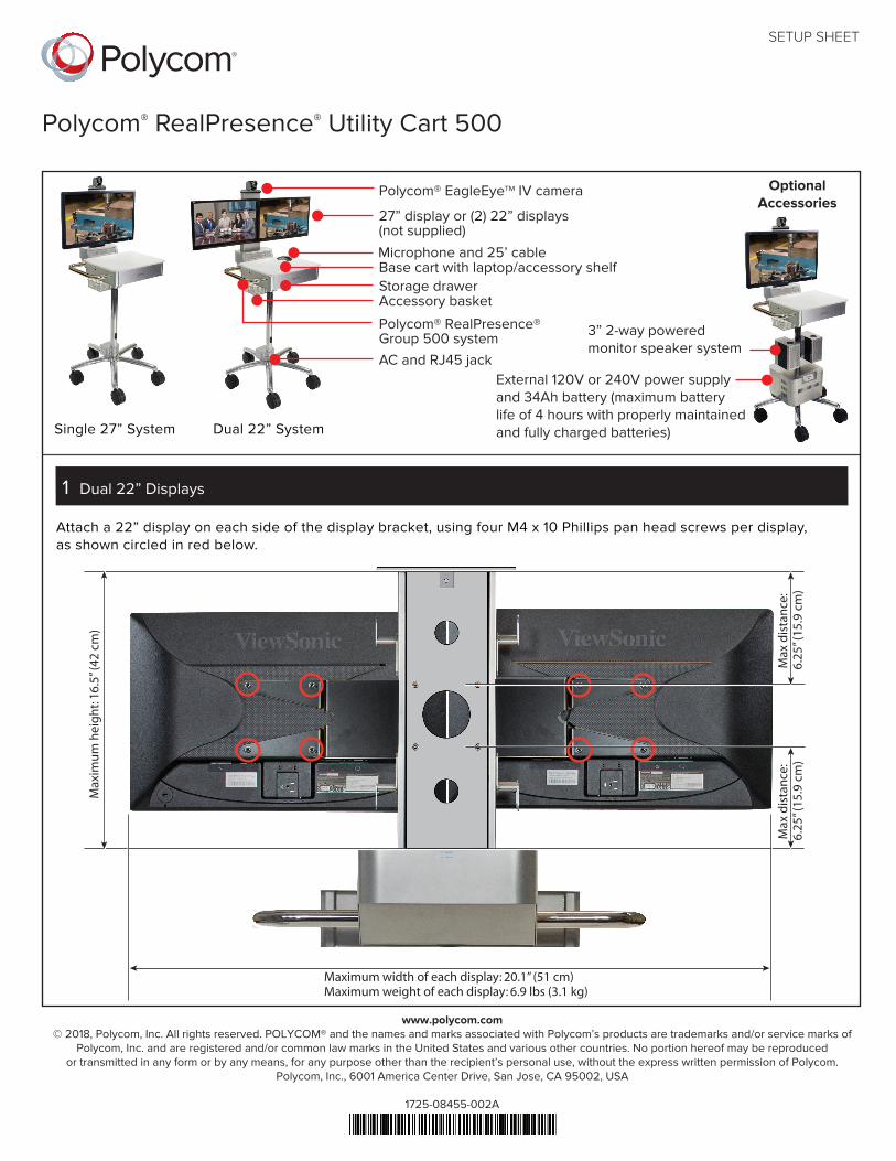
Single 27” System Dual 22” System
External 120V or 240V power supplyand 34Ah battery (maximum batterylife of 4 hours with properly maintainedand fully charged batteries)
OptionalAccessories
3” 2-way poweredmonitor speaker system
Polycom® EagleEyeTM IV camera
27” display or (2) 22” displays(not supplied)
Microphone and 25’ cableBase cart with laptop/accessory shelfStorage drawerAccessory basket
1 Dual 22” Displays
Polycom® RealPresence® Group 500 systemAC and RJ45 jack
Attach a 22” display on each side of the display bracket, using four M4 x 10 Phillips pan head screws per display,as shown circled in red below.
Polycom® RealPresence® Utility Cart 500
SETUP SHEET
Maximum width of each display: 20.1” (51 cm)Maximum weight of each display: 6.9 lbs (3.1 kg)
Max
imu
m h
eig
ht:
16.5
” (42
cm
)
Max
dis
tan
ce:
6.25
” (15
.9 c
m)
Max
dis
tan
ce:
6.25
” (15
.9 c
m)
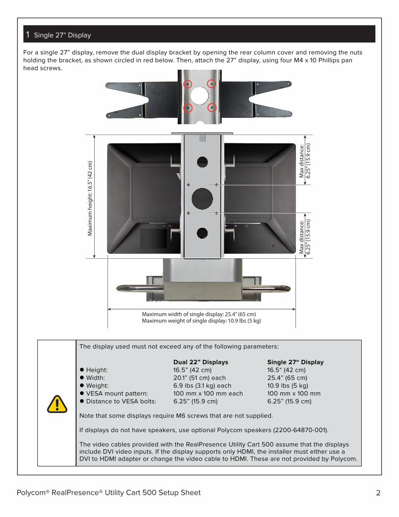
For a single 27” display, remove the dual display bracket by opening the rear column cover and removing the nutsholding the bracket, as shown circled in red below. Then, attach the 27” display, using four M4 x 10 Phillips panhead screws.
1 Single 27” Display
Polycom® RealPresence® Utility Cart 500 Setup Sheet 2
Maximum width of single display: 25.4” (65 cm)Maximum weight of single display: 10.9 lbs (5 kg)
Max
imu
m h
eig
ht:
16.5
” (42
cm
)
Max
dis
tan
ce:
6.25
” (15
.9 c
m)
Max
dis
tan
ce:
6.25
” (15
.9 c
m)
The display used must not exceed any of the following parameters:
Dual 22” Displays Single 27“ Display Height: 16.5” (42 cm) 16.5“ (42 cm) Width: 20.1” (51 cm) each 25.4” (65 cm) Weight: 6.9 lbs (3.1 kg) each 10.9 lbs (5 kg) VESA mount pattern: 100 mm x 100 mm each 100 mm x 100 mm Distance to VESA bolts: 6.25” (15.9 cm) 6.25” (15.9 cm)
Note that some displays require M6 screws that are not supplied.
If displays do not have speakers, use optional Polycom speakers (2200-64870-001).
The video cables provided with the RealPresence Utility Cart 500 assume that the displaysinclude DVI video inputs. If the display supports only HDMI, the installer must either use aDVI to HDMI adapter or change the video cable to HDMI. These are not provided by Polycom.

Polycom® RealPresence® Utility Cart 500 Setup Sheet 3
2
Attach the EagleEye IV camera to the camera base,using four M3 x 6 Phillips flat head screws. Tightenthe screws.
3
4
Mount the RealPresence Group 500 system underthe Utility Cart 500 drawer, using two M3 x 8mmPhillips pan head screws. Open the drawer to alloweasier access for mounting the system.
Install the RealPresence Group 500 system powersupply by removing the bottom plate. Insert thepower supply in the vertical position shown below,then flip it to a horizontal position, and reinstall thescrew on the power supply bracket. Connect thepre-installed AC power cable to the power supply.
Neatly route and connect the pre-installed cables,which are labeled. Refer to the wiring diagram atthe end of this document for details.
Polycom® RealPresence® Utility Cart 500 Setup Sheet 4
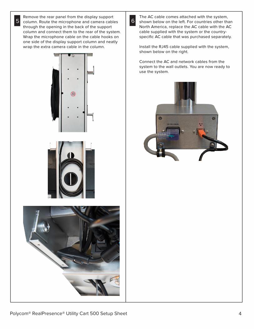
5Remove the rear panel from the display supportcolumn. Route the microphone and camera cablesthrough the opening in the back of the supportcolumn and connect them to the rear of the system.Wrap the microphone cable on the cable hooks onone side of the display support column and neatlywrap the extra camera cable in the column.
The AC cable comes attached with the system,shown below on the left. For countries other thanNorth America, replace the AC cable with the ACcable supplied with the system or the country-specific AC cable that was purchased separately.
Install the RJ45 cable supplied with the system,shown below on the right.
Connect the AC and network cables from thesystem to the wall outlets. You are now ready touse the system.
6

Polycom® RealPresence® Utility Cart 500 Setup Sheet 5
8 Optional Battery Pack and Power Supply Module
Remove the four screws and two cable clamps to openthe connection plate from the box and remove theconnectors from the connection plate.
Remove the AC input and RJ45 network connectionbox at the base of the cart by removing the four screwsthat attach the U-shaped brackets and connection boxto the base of the cart.
7Optional: Attach the utility shelf to either side of thedrawer. Open the drawer. You may have to unlockit first. Lift out the shelf.
Insert the shelf tabs into the side slots. The shelfrests on the side handle.

Polycom® RealPresence® Utility Cart 500 Setup Sheet 6
Move the two cables from the rear bottom hole in thepole to the front bottom hole. Attach the power supplybase to the optional power supply and battery pack.
120V power supply and 34Ah battery (2200-64870-110)The system should only be connected to a mainspower supply of 120V 60 Hz.
230V power supply and 34Ah battery (2200-64870-230)The system should only be connected to a mainspower supply of 230V 50Hz.
Attach the power supply to the cart, using the suppliedscrews.
Connect the RJ45 LAN cables from the power supplybase to the LAN ports on the power supply. Informationis transmitted to LEDs on the power supply cover.
9 Optional Battery Pack and Power Supply Module
10 Optional Battery Pack and Power Supply Module
11 Optional Battery Pack and Power Supply Module
12 Optional Battery Pack and Power Supply Module
Connect the input and output AC connector to thepower supply. Attach the power supply cover, using theU-shaped bracket and the supplied screws. Tighten thescrews.
Attach the RJ45 connector to the connector panel,using the previously removed hardware.

7
Insert the battery into the battery compartment andconnect the battery to the power supply.
Polycom® RealPresence® Utility Cart 500 Setup Sheet
3” 2-way powered monitor speaker system(2200-64870-001)
The optional powered speaker kit ships with thespeakers already installed in the speaker brackets.Remove the cover on the back of the speakers toexpose the Input B jack.
Remove the bottom plate (as shown in step 4), removethe rear panel from the display support column (as shownin step 6), and remove the drawer to allow easier accessfor installing the cables down the pole.
Move the audio cable from the display down the pole.Install the supplied AC power cable from the powerstrip and exit at the pole, as shown below. Pass thecables into the speaker assembly and attach thespeaker assembly to the pole.
14 Optional Battery Pack and Power Supply Module
15 Optional Powered Speaker Kit
16 Optional Powered Speaker Kit
Take extra precautions when installing andconnecting the battery due to high currentcapacity. Seek assistance from a trainedservice person or electrician, if necessary.
13 Optional Battery Pack and Power Supply Module
Attach the battery pack cover, using the supplied screws.Tighten the screws.
Reinstall the cable clamps removed in step 9.
8
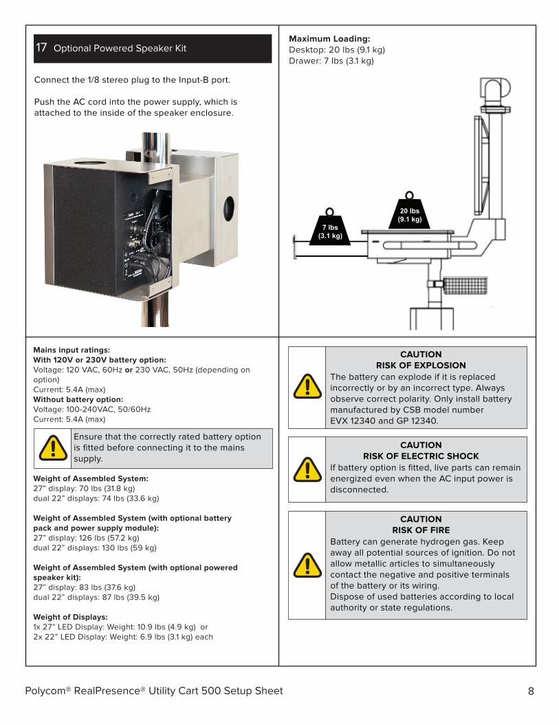
Connect the 1/8 stereo plug to the Input-B port.
Push the AC cord into the power supply, which isattached to the inside of the speaker enclosure.
Polycom® RealPresence® Utility Cart 500 Setup Sheet
17 Optional Powered Speaker Kit
Mains input ratings:With 120V or 230V battery option:Voltage: 120 VAC, 60Hz or 230 VAC, 50Hz (depending onoption)Current: 5.4A (max)Without battery option:Voltage: 100-240VAC, 50/60HzCurrent: 5.4A (max)
Weight of Assembled System:27” display: 70 lbs (31.8 kg)dual 22” displays: 74 lbs (33.6 kg)
Weight of Assembled System (with optional batterypack and power supply module):27” display: 126 lbs (57.2 kg)dual 22” displays: 130 lbs (59 kg)
Weight of Assembled System (with optional poweredspeaker kit):27” display: 83 lbs (37.6 kg)dual 22” displays: 87 lbs (39.5 kg)
Weight of Displays:1x 27” LED Display: Weight: 10.9 lbs (4.9 kg) or2x 22” LED Display: Weight: 6.9 lbs (3.1 kg) each
Ensure that the correctly rated battery optionis fitted before connecting it to the mainssupply.
CAUTIONRISK OF EXPLOSION
The battery can explode if it is replacedincorrectly or by an incorrect type. Alwaysobserve correct polarity. Only install batterymanufactured by CSB model numberEVX 12340 and GP 12340.
CAUTIONRISK OF ELECTRIC SHOCK
If battery option is fitted, live parts can remainenergized even when the AC input power isdisconnected.
CAUTIONRISK OF FIRE
Battery can generate hydrogen gas. Keepaway all potential sources of ignition. Do notallow metallic articles to simultaneouslycontact the negative and positive terminalsof the battery or its wiring.Dispose of used batteries according to localauthority or state regulations.
Maximum Loading:Desktop: 20 lbs (9.1 kg)Drawer: 7 lbs (3.1 kg)
20 lbs(9.1 kg)
7 lbs(3.1 kg)
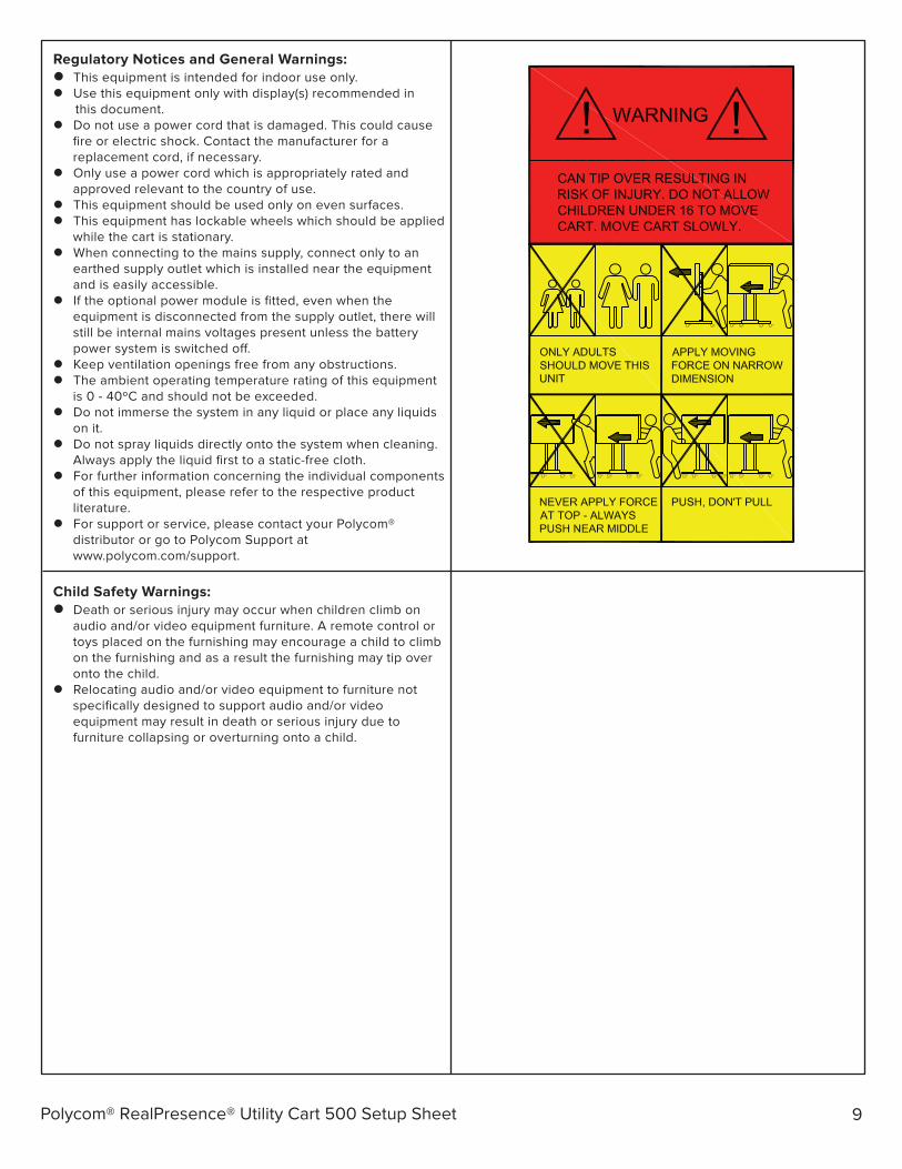
Regulatory Notices and General Warnings: This equipment is intended for indoor use only. Use this equipment only with display(s) recommended in
this document. Do not use a power cord that is damaged. This could cause
fire or electric shock. Contact the manufacturer for areplacement cord, if necessary.
Only use a power cord which is appropriately rated andapproved relevant to the country of use.
This equipment should be used only on even surfaces. This equipment has lockable wheels which should be applied
while the cart is stationary. When connecting to the mains supply, connect only to an
earthed supply outlet which is installed near the equipmentand is easily accessible.
If the optional power module is fitted, even when theequipment is disconnected from the supply outlet, there willstill be internal mains voltages present unless the batterypower system is switched o�.
Keep ventilation openings free from any obstructions. The ambient operating temperature rating of this equipment
is 0 - 40ºC and should not be exceeded. Do not immerse the system in any liquid or place any liquids
on it. Do not spray liquids directly onto the system when cleaning.
Always apply the liquid first to a static-free cloth. For further information concerning the individual components
of this equipment, please refer to the respective productliterature.
For support or service, please contact your Polycom®distributor or go to Polycom Support atwww.polycom.com/support.
9Polycom® RealPresence® Utility Cart 500 Setup Sheet
Child Safety Warnings: Death or serious injury may occur when children climb on
audio and/or video equipment furniture. A remote control ortoys placed on the furnishing may encourage a child to climbon the furnishing and as a result the furnishing may tip overonto the child.
Relocating audio and/or video equipment to furniture notspecifically designed to support audio and/or videoequipment may result in death or serious injury due tofurniture collapsing or overturning onto a child.
10Polycom® RealPresence® Utility Cart 500 Setup Sheet
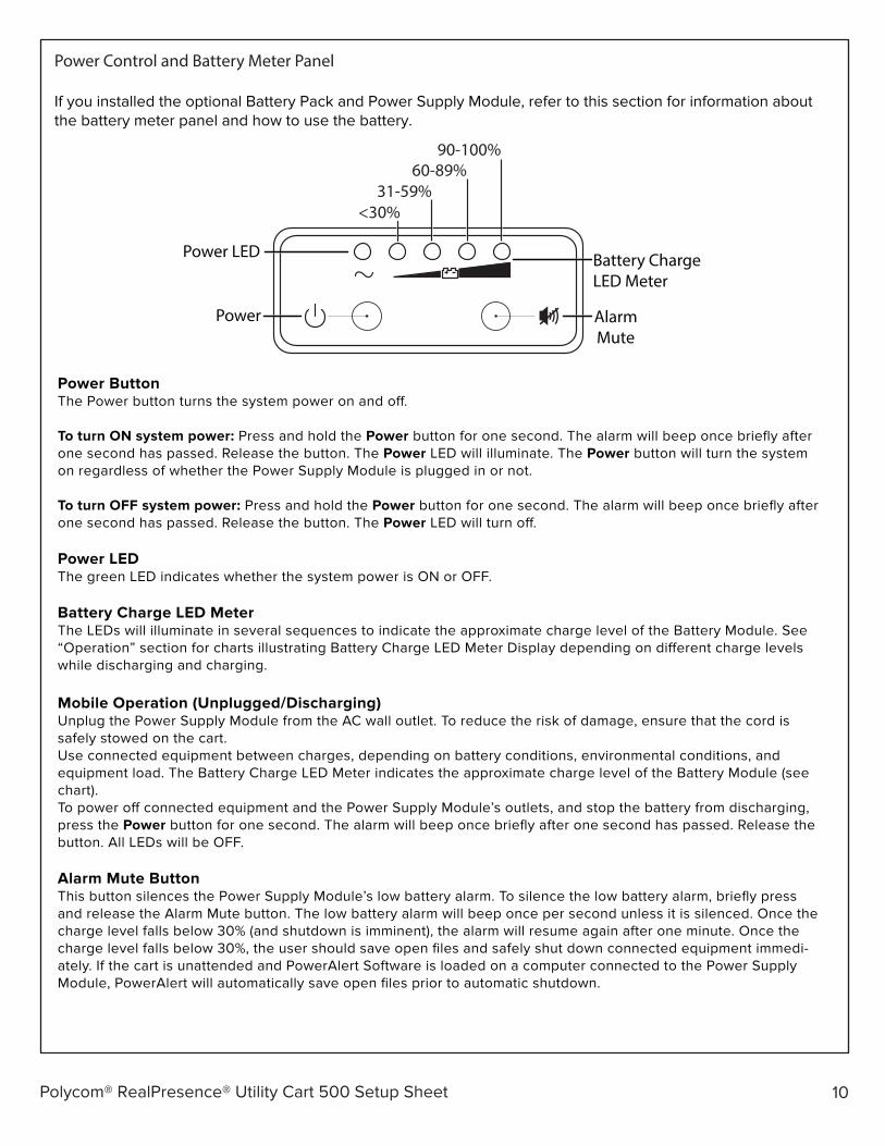
Power ButtonThe Power button turns the system power on and o�.
To turn ON system power: Press and hold the Power button for one second. The alarm will beep once briefly after one second has passed. Release the button. The Power LED will illuminate. The Power button will turn the system on regardless of whether the Power Supply Module is plugged in or not.
To turn OFF system power: Press and hold the Power button for one second. The alarm will beep once briefly after one second has passed. Release the button. The Power LED will turn o�.
Power LEDThe green LED indicates whether the system power is ON or OFF.
Battery Charge LED MeterThe LEDs will illuminate in several sequences to indicate the approximate charge level of the Battery Module. See “Operation” section for charts illustrating Battery Charge LED Meter Display depending on di�erent charge levels while discharging and charging.
Mobile Operation (Unplugged/Discharging)Unplug the Power Supply Module from the AC wall outlet. To reduce the risk of damage, ensure that the cord is safely stowed on the cart.Use connected equipment between charges, depending on battery conditions, environmental conditions, and equipment load. The Battery Charge LED Meter indicates the approximate charge level of the Battery Module (see chart).To power o� connected equipment and the Power Supply Module’s outlets, and stop the battery from discharging, press the Power button for one second. The alarm will beep once briefly after one second has passed. Release the button. All LEDs will be OFF.
Alarm Mute ButtonThis button silences the Power Supply Module’s low battery alarm. To silence the low battery alarm, briefly press and release the Alarm Mute button. The low battery alarm will beep once per second unless it is silenced. Once the charge level falls below 30% (and shutdown is imminent), the alarm will resume again after one minute. Once the charge level falls below 30%, the user should save open files and safely shut down connected equipment immedi-ately. If the cart is unattended and PowerAlert Software is loaded on a computer connected to the Power Supply Module, PowerAlert will automatically save open files prior to automatic shutdown.
Power Control and Battery Meter Panel
If you installed the optional Battery Pack and Power Supply Module, refer to this section for information aboutthe battery meter panel and how to use the battery.
Battery ChargeLED Meter
90-100%60-89%
31-59%<30%
Power AlarmMute
Power LED
11Polycom® RealPresence® Utility Cart 500 Setup Sheet
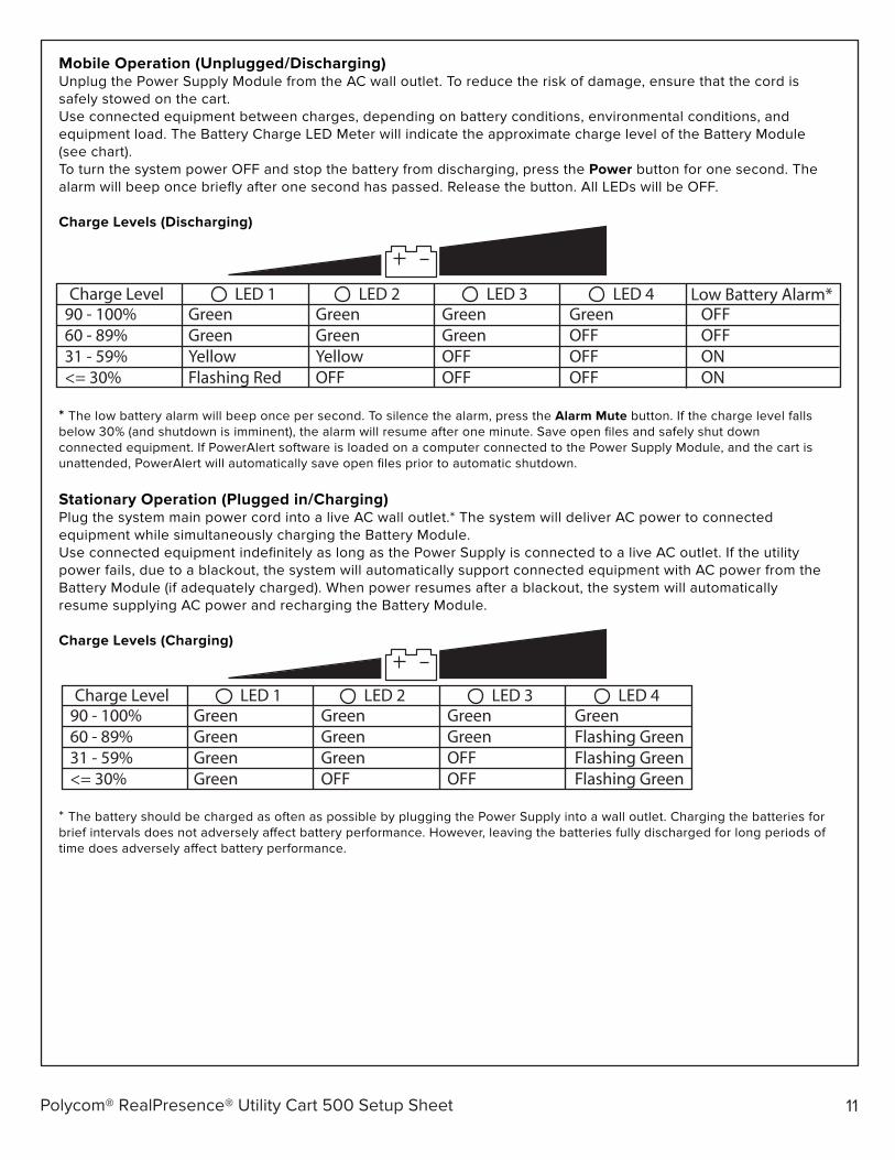
Mobile Operation (Unplugged/Discharging)Unplug the Power Supply Module from the AC wall outlet. To reduce the risk of damage, ensure that the cord is safely stowed on the cart.Use connected equipment between charges, depending on battery conditions, environmental conditions, and equipment load. The Battery Charge LED Meter will indicate the approximate charge level of the Battery Module (see chart).To turn the system power OFF and stop the battery from discharging, press the Power button for one second. The alarm will beep once briefly after one second has passed. Release the button. All LEDs will be OFF.
Charge Levels (Discharging)
* The low battery alarm will beep once per second. To silence the alarm, press the Alarm Mute button. If the charge level falls below 30% (and shutdown is imminent), the alarm will resume after one minute. Save open files and safely shut down connected equipment. If PowerAlert software is loaded on a computer connected to the Power Supply Module, and the cart is unattended, PowerAlert will automatically save open files prior to automatic shutdown.
Stationary Operation (Plugged in/Charging)Plug the system main power cord into a live AC wall outlet.* The system will deliver AC power to connected equipment while simultaneously charging the Battery Module.Use connected equipment indefinitely as long as the Power Supply is connected to a live AC outlet. If the utility power fails, due to a blackout, the system will automatically support connected equipment with AC power from the Battery Module (if adequately charged). When power resumes after a blackout, the system will automatically resume supplying AC power and recharging the Battery Module.
Charge Levels (Charging)
* The battery should be charged as often as possible by plugging the Power Supply into a wall outlet. Charging the batteries for brief intervals does not adversely a�ect battery performance. However, leaving the batteries fully discharged for long periods of time does adversely a�ect battery performance.
90 - 100%60 - 89%31 - 59%<= 30%
GreenGreenGreenGreen
GreenGreenGreenOFF
GreenGreenOFFOFF
GreenFlashing GreenFlashing GreenFlashing Green
LED 1 LED 2 LED 3 LED 4Charge Level
90 - 100%60 - 89%31 - 59%<= 30%
GreenGreenYellowFlashing Red
GreenGreenYellowOFF
GreenGreenOFFOFF
GreenOFFOFFOFF
LED 1 LED 2 LED 3 LED 4Charge LevelOFFOFFONON
Low Battery Alarm*

12Polycom® RealPresence® Utility Cart 500 Setup Sheet
Utility Cart 500 Wiring Diagram