
Pneumatic Mini Belt Sander - Jegs High Performance JAT-750/751/752 Mini Belt Sanders Warranty and...
21
Pneumatic Mini Belt Sander #505750, JAT-750 #505751, JAT-751 #505752, JAT-752 Operation & Parts Manual M-505750 Edition 2 06/2015 JET 427 New Sanford Road LaVergne, TN 37086 Ph.: 800-274-6848 www.jettools.com Copyright © 2015 JET JAT-750 JAT-752 JAT-751
-
Upload
nguyendang -
Category
Documents
-
view
222 -
download
7
Transcript of Pneumatic Mini Belt Sander - Jegs High Performance JAT-750/751/752 Mini Belt Sanders Warranty and...

Pneumatic Mini Belt Sander #505750, JAT-750 #505751, JAT-751 #505752, JAT-752
Operation & Parts Manual M-505750
Edition 2 06/2015
JET 427 New Sanford Road
LaVergne, TN 37086 Ph.: 800-274-6848 www.jettools.com
Copyright © 2015 JET
JAT-750
JAT-752
JAT-751

2 JAT-750/751/752 Mini Belt Sanders
Warranty and Service JET warrants every product it sells against manufacturers’ defects. If one of our tools needs service or repair, please contact Technical Service by calling 1-800-274-6846, 8AM to 5PM CST, Monday through Friday.
Warranty Period The general warranty lasts for the time period specified in the literature included with your product or on the official JET branded website.
• JET products carry a limited warranty which varies in duration based upon the product. (See chart below) • Accessories carry a limited warranty of one year from the date of receipt. • Consumable items are defined as expendable parts or accessories expected to become inoperable within a
reasonable amount of use and are covered by a 90 day limited warranty against manufacturer’s defects.
Who is Covered This warranty covers only the initial purchaser of the product from the date of delivery.
What is Covered This warranty covers any defects in workmanship or materials subject to the limitations stated below. This warranty does not cover failures due directly or indirectly to misuse, abuse, negligence or accidents, normal wear-and-tear, improper repair, alterations or lack of maintenance. JET woodworking machinery is designed to be used with Wood. Use of these machines in the processing of metal, plastics, or other materials outside recommended guidelines, may void the warranty. The exceptions are acrylics and other natural items that are made specifically for wood turning.
Warranty Limitations Woodworking products with a Five Year Warranty that are used for commercial or industrial purposes default to a Two Year Warranty. Please contact Technical Service at 1-800-274-6846 for further clarification.
How to Get Technical Support Please contact Technical Service by calling 1-800-274-6846. Please note that you will be asked to provide proof of initial purchase when calling. If a product requires further inspection, the Technical Service representative will explain and assist with any additional action needed. JET has Authorized Service Centers located throughout the United States. For the name of an Authorized Service Center in your area call 1-800-274-6846 or use the Service Center Locator on the JET website.
More Information JET is constantly adding new products. For complete, up-to-date product information, check with your local distributor or visit the JET website.
How State Law Applies This warranty gives you specific legal rights, subject to applicable state law.
Limitations on This Warranty JET LIMITS ALL IMPLIED WARRANTIES TO THE PERIOD OF THE LIMITED WARRANTY FOR EACH PRODUCT. EXCEPT AS STATED HEREIN, ANY IMPLIED WARRANTIES OF MERCHANTABILITY AND FITNESS FOR A PARTICULAR PURPOSE ARE EXCLUDED. SOME STATES DO NOT ALLOW LIMITATIONS ON HOW LONG AN IMPLIED WARRANTY LASTS, SO THE ABOVE LIMITATION MAY NOT APPLY TO YOU. JET SHALL IN NO EVENT BE LIABLE FOR DEATH, INJURIES TO PERSONS OR PROPERTY, OR FOR INCIDENTAL, CONTINGENT, SPECIAL, OR CONSEQUENTIAL DAMAGES ARISING FROM THE USE OF OUR PRODUCTS. SOME STATES DO NOT ALLOW THE EXCLUSION OR LIMITATION OF INCIDENTAL OR CONSEQUENTIAL DAMAGES, SO THE ABOVE LIMITATION OR EXCLUSION MAY NOT APPLY TO YOU. JET sells through distributors only. The specifications listed in JET printed materials and on official JET website are given as general information and are not binding. JET reserves the right to effect at any time, without prior notice, those alterations to parts, fittings, and accessory equipment which they may deem necessary for any reason whatsoever. JET® branded products are not sold in Canada by JPW Industries, Inc.
Product Listing with Warranty Period 90 Days – Parts; Consumable items 1 Year – Motors; Machine Accessories 2 Year – Metalworking Machinery; Electric Hoists, Electric Hoist Accessories; Woodworking Machinery used for industrial or commercial purposes 5 Year – Woodworking Machinery Limited Lifetime – JET Parallel clamps; VOLT Series Electric Hoists; Manual Hoists; Manual Hoist Accessories; Shop Tools; Warehouse & Dock products; Hand Tools; Air Tools
NOTE: JET is a division of JPW Industries, Inc. References in this document to JET also apply to JPW Industries, Inc., or any of its successors in interest to the JET brand.

JET 3
Safety warnings General air tool warnings 1. Read and understand this entire manual
before attempting assembly or operation.
2. Read and understand all warnings posted on the tool and in this manual. Failure to comply with all of these warnings may cause serious injury.
3. Replace warning labels if they become obscured or removed.
4. Do not use this tool for other than its intended use. If used for other purposes, JET disclaims any real or implied warranty and holds itself harmless from any injury that may result from that use.
5. Always wear approved safety glasses or face shield while using this tool. (Everyday eyeglasses only have impact resistant lenses; they are not safety glasses.)
6. Wear ear protectors (plugs or muffs) if the noise exceeds safe levels.
7. Wear gloves and protective clothing if operation produces sparks or flying particles. Gloves should be tight-fitting, without frayed fingers or hanging threads. Keep hands and body away from the working area of tool.
8. Some dust created by power sanding, sawing, grinding, drilling and other construction activities contains chemicals known to cause cancer, birth defects or other reproductive harm. Some examples of these chemicals are:
• Lead from lead based paint.
• Crystalline silica from bricks, cement and other masonry products.
• Arsenic and chromium from chemically treated lumber.
Your risk of exposure varies, depending on how often you do this type of work. To reduce your exposure to these chemicals, work in a well-ventilated area and work with approved safety equipment, such as face or dust masks that are specifically designed to filter out microscopic particles.
9. Do not operate an air tool continually at full throttle without a work load on the tool.
10. The air tool must be properly lubricated before operating.
11. Never start a percussion type air tool (chipper, breaker, buster, etc.) without securing the tooling in the retainer and placing the tip against the work surface.
12. Do not operate air tool without its guards in place. Do not modify the tool.
13. Do not operate this tool while tired or under the influence of drugs, alcohol, or any medication.
14. Adopt a comfortable posture with proper balance, and maintain secure footing at all times. Non-slip footwear or anti-skid floor strips are recommended.
15. Do not wear loose clothing or jewelry. Confine long hair.
16. Excessive air pressure and too much free rotation may decrease life of the tool and may cause a hazardous situation.
17. Check air hoses for wear, and keep them away from heat and sharp edges. Repair or replace damaged air hose immediately. Do not carry tool by the air hose.
18. Air hose may cause tripping hazards; keep hose away from traffic areas.
19. Do not use this tool near flammable objects, or in potentially explosive environments. Do not use near live electrical wires.

4 JAT-750/751/752 Mini Belt Sanders
20. Do not use power tools in damp or wet location, or expose them to rain. Keep work area well lighted.
21. Do not leave a connected tool unattended. When not in use, disconnect tool from air source.
22. Shut off air supply and discharge any residual pressure from tool before removing hose, making adjustments, changing accessories, or storing tool.
23. Make sure tool is switched off, and your finger off the trigger, before connecting to air supply.
24. Remove adjusting keys and wrenches before turning on tool.
25. Keep visitors a safe distance from the work area. Keep children away.
26. Give your work undivided attention. Looking around, carrying on a conversation and “horse-play” are careless acts that can result in serious injury.
27. Do not force a tool or attachment to do a job for which it was not designed. The right tool will do the job better and more safely.
28. Repetitive motions and/or exposure to constant vibration can be harmful to hands and arms. Take frequent breaks and relax hands during extended operation. Change posture to avoid discomfort or fatigue.
29. Compressed air can be harmful if directed toward sensitive areas of the body, and may propel small particles caught in the air stream. Exercise proper caution.
30. Use only recommended accessories; improper accessories may be hazardous.
31. Maintain tools with care. Keep air tool clean and oiled for best and safest performance.
32. Do not use combustible gases, carbon dioxide, oxygen or any bottled gas as an air source for the tool. These can present risk of explosion and serious injury.
33. Do not lubricate the tool with combustible liquids, such as kerosene, diesel or jet fuel.
34. Do not dispose of this tool with normal household waste. Never dispose of the air tool into fire.
Specific warnings for Belt Sanders 35. If you are not familiar with the proper and safe
operation of a pneumatic belt sander, do not use until proper training and knowledge have been obtained.
36. Secure workpiece with clamps or vise; do not hold workpiece by hand.
37. Only use accessories that are intended for use with a pneumatic belt sander.
38. Use both hands to operate sander.
39. Inspect abrasive belt before operating. Do not use a damaged belt.
40. Do not operate sander without the silencer (muffler) installed.
Familiarize yourself with the following safety notices used in this manual:
This means that if precautions are not heeded, it may result in serious, or even fatal, injury.
This means that if precautions are not heeded, it may result in minor injury and/or possible tool damage.

JET 5
About this manual This manual is provided by JET, covering the safe operation and maintenance procedures for a JET Model JAT-750, JAT-751 and JAT-752 Pneumatic Mini Belt Sander. This manual contains instructions on safety precautions, general operating procedures, maintenance procedures and parts breakdown. Your tool has been designed and constructed to provide consistent, long-term operation if used in accordance with the instructions set forth in this document.
The instructions and warnings in this manual may not encompass all possible workplace environments. The operator is expected to take appropriate precautions and exercise common sense. As with any tool operation, safety of operator and bystanders should be first priority.
If there are questions or comments, please contact your local supplier or JET. JET can also be reached at our web site: www.jettools.com.
Record the serial number and purchase information of your tool on the cover of this manual for quick access. Retain this manual for future reference. If the tool transfers ownership, the manual should accompany it.

6 JAT-750/751/752 Mini Belt Sanders
Tool specifications Model number JAT-750 JAT-751 JAT-752 Stock number 505750 505751 505752 Belt size 3/8 x 13 in. 3/4 x 20-1/2 in. 1/2 x 24 in. Horsepower 0.5 0.6 0.5 Head rotation 360 deg. 360 deg. 360 deg. Free speed 20,000 RPM 18,000 20,000 Average air consumption 4.2 CFM 4.2 CFM 4.2 CFM Air inlet 1/4 in. NPT 1/4 in. NPT 1/4 in. NPT Air hose inside diameter 3/8 in. 3/8 in. 3/8 in. Required air pressure 90 psi (621 kPa) 90 psi (621 kPa) 90 psi (621 kPa) Vibration value 1.3 m/s2 3.1 m/s2 1.3 m/s2 Noise level 1 93 dB(A) 96 dB(A) 93 dB(A) Power setting Variable speed throttle Variable speed throttle Variable speed throttle
Grip inline inline inline Overall length, folded 8-1/8 in. (206.38 mm) 10 in. (254 mm) 12-1/4 in. (311.15 mm)
Overall length, maximum 13 in. (330.2 mm) 15-3/4 in. (400 mm) 18-1/2 in. (470 mm)
Housing material Aluminum with rubber grip
Aluminum with rubber grip
Aluminum with rubber grip
Net weight 1.94 lb. (0.88 kg) 2.98 lb. (1.35 kg) 2.14 lb. (0.97 kg) Shipping weight 2.27 lb. (1.03 kg) 3.37 lb. (1.53 kg) 2.51 lb. (1.14 kg)
1 The specified values are emission levels and are not necessarily to be seen as safe operating levels. As workplace conditions vary, this information is intended to allow the user to make a better estimation of the hazards and risks involved only.
Specifications were current at time of publication, but because of our policy of continuous improvement, JET reserves the right to change specifications at any time and without prior notice, without incurring obligations.

JET 7
Setup and Assembly Any missing parts or damage should be reported immediately to your JET® distributor. Do not use a damaged tool. Read this instruction manual thoroughly for operation, maintenance and safety instructions.
Box contents: 1 Mini belt sander 2 Sanding belts (one is pre-installed) 1 Hex wrench 4mm 1 Operation and parts manual 1 Warranty card
Operation The belt sander must be
properly lubricated before operation. See “Lubrication” section.
Disconnect sander from air hose before making any repair or adjustment.
Figure 1
1. Adjust arm to desired angle and tighten hex socket cap screw (Figure 1), with supplied hex wrench. Make sure arm assembly is fitted closely to housing shoulder.
Always tighten hex socket cap screw firmly after adjustment, or the head could rotate, causing loss of control.
2. Remove protective cap from air inlet. If an in-line oiler is not being used, add 4 or 5 drops of air tool oil (not included) into the air inlet.
3. Blow out air line to remove any dirt or moisture, then connect air supply hose to tool. Set air pressure to 90 psi.
IMPORTANT: Connecting a quick-change coupling directly to the tool is not recommended, as vibration may cause the connection to fail. Instead, add a leader hose and install any quick-change couplings farther down the line.
4. Grip sander securely and push safety lever backward to release throttle lever. Gently press throttle lever.
5. Place sanding belt on workpiece and move tool back and forth with light pressure. Do not apply excessive pressure, as it may damage workpiece and hasten wear on sanding belt.
Adjustments Tracking adjustment
Tracking adjustment requires sander to be connected to the hose and running. Use caution when hands and tools are close to a running belt.
Belt is tracking properly on all models when centered on the idle pulley.
JAT-750/752:
1. Disconnect sander from air source.
2. Loosen set screw with 1.5mm hex wrench (not provided). See Figure 2.
3. With belt running, turn adjusting screw clockwise or counterclockwise until belt is centered on idle pulley.
4. Tighten set screw.

8 JAT-750/751/752 Mini Belt Sanders
Figure 2
JAT-751:
Insert hex wrench into hex socket cap screw and turn clockwise or counterclockwise until belt is centered on idle pulley. See Figure 4.
Figure 3
Belt replacement JAT-750:
1. Disconnect sander from air source.
2. Loosen hex cap screw (See Figure 1), turn arm 90-degrees to the handle, and tighten screw to lock.
3. Steady sander with one hand while pushing down on the idle wheel with other hand, until assembly locks in place. See Figure 4.
4. Remove old belt. Install new belt, centering it on the pulleys.
5. Press tension lever (A, Figure 4) to engage tension.
Figure 4: JAT-750
JAT-751:
1. Disconnect sander from air source.
2. Loosen hex cap screw (see Figure 1), turn head 90-degrees to the handle, and tighten screw to lock.
3. Steady sander with one hand, while pushing down on idle pulley assembly and removing belt.
4. Install new belt over pulleys.
5. Release pressure on idle pulley to tension belt.
Figure 5: JAT-751
JAT-752:
1. Disconnect sander from air source.
2. Loosen hex cap screw (see Figure 1), turn head 90-degrees to the handle, and tighten screw to lock.
JET 9
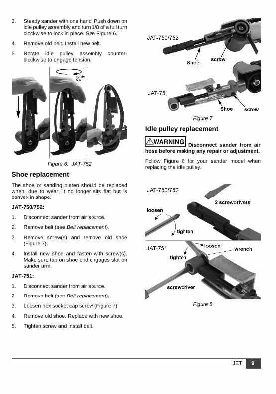
3. Steady sander with one hand. Push down on idle pulley assembly and turn 1/8 of a full turn clockwise to lock in place. See Figure 6.
4. Remove old belt. Install new belt.
5. Rotate idle pulley assembly counter-clockwise to engage tension.
Figure 6: JAT-752
Shoe replacement The shoe or sanding platen should be replaced when, due to wear, it no longer sits flat but is convex in shape.
JAT-750/752:
1. Disconnect sander from air source.
2. Remove belt (see Belt replacement).
3. Remove screw(s) and remove old shoe (Figure 7).
4. Install new shoe and fasten with screw(s). Make sure tab on shoe end engages slot on sander arm.
JAT-751:
1. Disconnect sander from air source.
2. Remove belt (see Belt replacement).
3. Loosen hex socket cap screw (Figure 7).
4. Remove old shoe. Replace with new shoe.
5. Tighten screw and install belt.
Figure 7
Idle pulley replacement
Disconnect sander from air hose before making any repair or adjustment.
Follow Figure 8 for your sander model when replacing the idle pulley.
Figure 8

10 JAT-750/751/752 Mini Belt Sanders
Tension bar replacement JAT-750/752:
1. Disconnect sander from air source.
2. Remove belt.
3. Pull out tension bar from housing, Figure 9. Be careful not to lose spring.
4. Insert new tension bar by lining up pin with pin groove. See Figure 9.
Figure 9
Speed adjustment All models have a brass screw on the underside of the handle, used for belt speed adjustment. This has been set by the manufacturer; it is highly recommended that the end user not attempt any adjustment to the speed control.
Maintenance Lubrication The sander should be lubricated daily (or before each use) with air tool oil through the air inlet. During continual operation, it should be re-oiled every 1 to 2 hours. This can be done with an in-line oiler, or manually. If done manually, proceed as follows:
1. Disconnect air hose from tool.
2. Place 4 or 5 drops of air tool oil into air inlet.
NOTE: Air tool oil not provided; it is available at most major hardware and tool stores. SAE #10 oil or sewing machine oil may be used as a substitute. Do not use detergent oil.
3. Re-connect air. Run tool at low throttle without load for a few seconds to distribute the oil throughout tool.
4. When finished operating tool, disconnect air hose. Wipe off housing with a dry cloth. Place 4 or 5 drops of air tool oil into air inlet; re-connect air and run tool for a few seconds to distribute the oil. Disconnect air.
Storage Avoid storing the sander in very humid locations which promotes rusting of internal mechanisms. Always oil the tool and disconnect air hose before storage.
Air system requirements 1. Use proper air hose size (refer to tool
specifications). The hose should be just long enough to serve the working area. Excessive hose length will cause pressure drop.
2. Make sure air compressor supplies clean, dry air at correct CFM for the tool.
3. Set air pressure to 90 psi.
Excess air pressure and/or unclean air will shorten the tool’s life and may create a hazardous situation.
4. Drain water from air compressor tank daily, as well as any condensation from air lines. Water in the air line may enter the tool and cause damage.
5. Change filters on the air system on a regular basis.
6. Air-line pressure may be increased accordingly to compensate for extra-long air hoses (usually over 25 feet). Inside diameter of hose should be minimum 3/8-inch.
General Air Tool Information If the air tool is not performing according to specifications, the following are among the most common causes. (See also “Troubleshooting” section.)
• Contaminated air such as a dirty air system or water in the system.
• Using wrong size tool for the job. • Poor maintenance practices, such as using
excessive air pressure or air volume. • Improper or no lubrication.
JET 11
Rule of Thumb If it takes more than 8 seconds to tighten or loosen a bolt or nut with an air impact wrench at maximum setting, the air wrench is too small or the air compressor CFM is not powerful enough for the job. Continued use in either capacity will cause damage to the tool.
Tool Pressure JET Air Tools operate on 70-to-100 psi (pounds per square inch) air pressure measured at the tool when the tool is operating. Set tool to 90 psi unless indicated otherwise. Pressure in excess of 100 psi will shorten the life of the tool.
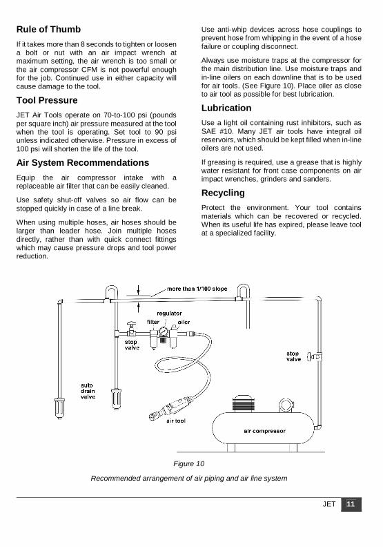
Air System Recommendations Equip the air compressor intake with a replaceable air filter that can be easily cleaned.
Use safety shut-off valves so air flow can be stopped quickly in case of a line break.
When using multiple hoses, air hoses should be larger than leader hose. Join multiple hoses directly, rather than with quick connect fittings which may cause pressure drops and tool power reduction.
Use anti-whip devices across hose couplings to prevent hose from whipping in the event of a hose failure or coupling disconnect.
Always use moisture traps at the compressor for the main distribution line. Use moisture traps and in-line oilers on each downline that is to be used for air tools. (See Figure 10). Place oiler as close to air tool as possible for best lubrication.
Lubrication Use a light oil containing rust inhibitors, such as SAE #10. Many JET air tools have integral oil reservoirs, which should be kept filled when in-line oilers are not used.
If greasing is required, use a grease that is highly water resistant for front case components on air impact wrenches, grinders and sanders.
Recycling Protect the environment. Your tool contains materials which can be recovered or recycled. When its useful life has expired, please leave tool at a specialized facility.
Figure 10
Recommended arrangement of air piping and air line system

12 JAT-750/751/752 Mini Belt Sanders
Troubleshooting JAT-750/751/752 Belt Sanders Any disassembly of the tool should be done by qualified service personnel. For problems not addressed below, contact JET technical service at 800-274-6846.
Problem Possible cause Remedy
Tool will not start. Air valve closed or obstructed. Open valve; clear any obstructions. Dirt or gum deposits on components.
Flush tool with gum solvent. If problem persists, disassemble, clean and lubricate internal parts.
Rotor vanes or other components are worn.
Replace worn components. (Replace vanes as complete set.)
Throttle lever inoperable. Clean throttle lever mechanism to ensure free movement. Replace mechanism if needed.
Bearing(s) worn. Disassemble and inspect bearing. Grease or replace as needed.
Starts immediately when air is connected without throttle lever being pressed.
Throttle lever malfunction. Clean throttle lever mechanism to ensure free movement. Replace mechanism if needed.
Excessive or abnormal vibration.
Bearings worn. Disassemble and inspect bearing. Grease or replace as needed.
Loss of power; erratic action.
Low air pressure. Verify compressor has proper CFM rating for tool. Check compressor regulator setting; set air pressure to 90 psi. Set regulator dial on tool to maximum setting. Check for loose connections.
Moisture or obstruction in air hose.
Air supply must be clean and dry. Clean out air hose(s) and remove any kinks or bends.
Improper size of air transmission lines, hoses, fittings, or couplings.
Use appropriate-sized air lines/ hoses. Verify proper fittings or couplings.
Dirt or gum deposits on components.
Flush tool with gum solvent. Check and clean air filter on compressor. Clean external areas of tool. If problem persists, disassemble, clean and lubricate internal parts.
Rotor vanes are worn. Replace vanes (entire set). Excessive heat develops in tool.
Insufficient lubrication. Lubricate with air tool oil. Worn components. Replace components as needed.
Severe air leakage. (Note: Minimal escape of air is often normal for air tools.)
Air valve obstructed or damaged. Clean or replace. Housing loose or damaged. Tighten or replace as needed.

JET 13
Replacement parts Replacement parts are listed on the following pages. To order parts or reach our service department, call 1-800-274-6848 Monday through Friday, 8:00 a.m. to 5:00 p.m. CST. Please have the stock number and serial number of your tool available when you call, so that we may serve you quickly and accurately.
14 JAT-750/751/752 Mini Belt Sanders
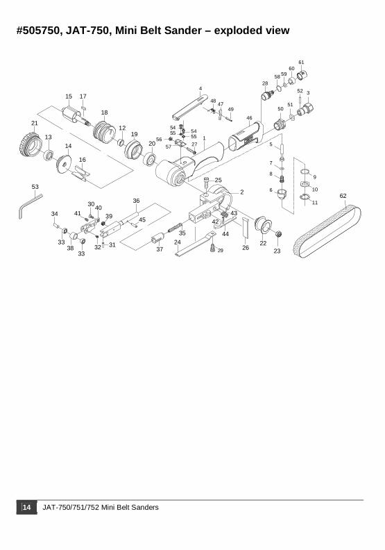
#505750, JAT-750, Mini Belt Sander – exploded view
23
35
16
13
21
15 17
1219
20
2624
4433
3430
41
37
3940
32 31
45
36
4342
25
22
253
3833
14
51
11
9
10
8
6
7
46
5
352
50
28
56
49
54155
55
57
54
47
4
48
27
18
58 5960
61
29
62

JET 15
#505750, JAT-750, Mini Belt Sander – parts listIndex Part No. Description Qty
1 JAT750-01 Housing (incl. #46 grip) 1 2 JAT750-02 Guard 1 JAT750-02A Guard subassembly (w/#26) 1 3 JSM6100-03 Air inlet 1 4 JSM6100-04 Throttle lever 1
JSM6100-04A Throttle lever assembly (incl. #4,47,48,49) 1
5 JSM6100-05 Valve stem 1 6 JSM6100-06 Valve 1 7 SM-30107 O-Ring 3.9x1.9 1 8 JSM6100-08 Spring 1 9 JSM6100-09 O-Ring 14.5x1.5 1 10 JSM6100-10 Spacer 1 11 JSM6100-11 Retaining ring RTW-18 1 12 61012 Spacer 1 13 BB-607ZZ Ball bearing 607ZZ 1 14 61014 Rear end plate 1 15 61015 Rotor 1 16 61016 Rotor vane 4 17 61017 Key 3x3x10 1 18 61018 Cylinder 1 19 61019 Front end plate 1 20 BB-628ZZ Ball bearing 628ZZ 1 21 61021 Cap 1 22 61222 Drive pulley 1 23 TS-1541021 Nylon lock hex nut M6 1 24 61024 Shoe 1 25 40343 Screw M5x16L 1 26 61026 Dust shield 1 27 JSM6100-27 Pan head screw M4x25 1 28 JSM6100-28 Exhaust shaft 1
JSM6100-28A Exhaust assembly (incl. #28,58-61) 1
29 TS-2284082 Pan head screw M4x8 1
Index Part No. Description Qty30 61035 Flat head screw M3x8 1 31 61036 Spring pin 3x10 1 32 61037 Pan hd. screw M2x5 1 33 BB-684ZZ Ball bearing 684ZZ 2 34 61039 Idle pulley shaft 1 35 61040 Spring 1 36 61041 Tension bar 1 37 61042 Bushing 1 38 61043 Idle pulley 1 39 61044 Spring 1 40 61045 Bracket 1 41 61046 Set screw M3x6 1 42 61048 Spring pin 2.5x8 1 43 61049 Spring 1 44 61050 Tension lever 1 45 JSM6100-45 Lock pin 3x11.8 1 46 JAT750-46 Rubber Grip 1 47 JSM6100-47 Safety lever 1 48 JSM6100-48 Spring 1 49 40337 Spring pin 3x18L 1 50 JSM6100-51 Screw 1 51 SM-40130 O-Ring 8.8x1.7 1 52 JSM6100-52 Pin 2x13.8 1 53 TS-152705 Hex wrench 4mm 1 54 TS-2284082 Pan head screw M4x8 2 55 TS-2361041 Spring washer M4 2 56 TS-2331041 Lock nut M4 1 57 JSM6100-57 Lever support 1 58 JSM5130-35 O-Ring 14x1 1 59 JSM6100-59 O-Ring 5.8x1.9 1 60 JSM6100-60 Muffler 1 61 JSM6100-61 Exhaust sleeve 1 62 JAT750-62 Sanding belt 120G 1
RPK-6100, Repair Kit, contains #7,9,11,16(4),26
RBK-6100, Rebuild Kit, contains #30-34,38-41

16 JAT-750/751/752 Mini Belt Sanders
#505751, JAT-751, Mini Belt Sander – exploded view
21
11
3435
3736 14
13
18
1517
16
1219
20
10
9
5
7
8
6
25
26
1
29
32
28
31
30
4
2
47
22
23
49
3325
38
24
39
40
4443
4148
43
42
36
4645
50
5152 53
356
5554
57
58
27

JET 17
#505751, JAT-751, Mini Belt Sander – parts listIndex Part No. Description Qty
1 JAT751-01 Housing (incl. #57 Grip) 1 2 JAT751-02 Guard 1 JAT751-02A Guard Subassembly (w/#26) 3 JSM6100-03 Air inlet 1 4 JSM6100-04 Throttle lever 1
JSM6100-04A
Throttle lever assembly (incl. #4,51,52,53) 1
5 JSM6100-05 Valve stem 1 6 JSM6100-06 Valve 1 7 SM-30107 O-Ring 3.9x1.9 1 8 JSM6100-08 Spring 1 9 JSM6100-09 O-Ring 14.5x1.5 1 10 JSM6100-10 Spacer 1 11 JSM6100-11 Retaining ring RTW-18 1 12 JAT751-12 Spacer 1 13 BB-608ZZ Ball bearing 608ZZ 1 14 JAT751-14 Rear end plate 1 15 JAT751-15 Rotor 1 16 JAT751-16 Rotor vane 4 17 JAT751-17 Key 4x4x10 1 18 JAT751-18 Cylinder 1 19 JAT751-19 Front end plate 1 20 BB-6000ZZ Ball bearing 6000ZZ 1 21 JAT751-21 Cap 1 22 JAT751-22 Drive pulley 1 23 TS-1541041 Nylon lock hex nut M10 1 24 JAT751-24 Shoe 1 25 JHM610-54 Socket hd cap screw M5x18L 1 26 JAT751-26 Dust shield 1 27 JAT751-27 Silencer 1 28 JSM6100-27 Pan head screw M4x25 1
Index Part No. Description Qty29 JSM6100-57 Lever support 1 30 TS-2284082 Pan hd screw M4x8L 2 31 TS-2361041 Spring washer M4 2 32 TS-2331041 Lock nut M4 1 33 JAT751-33 Bushing 1 34 JAT751-34 Finger pad 1 35 TS-1550031 Flat washer M5 1 36 TS-2361051 Spring washer M5 1 37 TS-1502011 Socket hd cap screw M5x8L 1 38 JAT751-38 Spring 1 39 JAT751-39 Arm 1 40 TS-2331061 Nylon lock hex nut M6 1 41 JAT751-41 Idle pulley 1 42 JAT751-42 Idle pulley shaft 1 43 BB-686ZZ Ball bearing 686ZZ 2 44 JAT751-44 Spacer 1 45 JAT741-09 Retaining ring ETWJ-4 1 46 JAT751-46 Bolt 1 47 TS-1502031 Socket hd cap screw M5x12L 1 48 JAT751-48 Spacer 1 49 JAT751-49 Sanding belt 120G 1 50 JSM3330-49 O-Ring 26.7x1.78 1 51 JSM6100-48 Spring 1 52 JSM6100-47 Safety lever 1 53 40337 Spring pin 3x18L 1 54 JSM6100-51 Screw 1 55 SM-40130 O-Ring 8.8x1.7 1 56 JSM6100-52 Pin 2x13.8 1 57 JAT750-46 Rubber Grip 1 58 TS-152705 Hex wrench 4mm 1
JAT751-RPK, Repair Kit, contains #7,9,11,16(4),26
JAT751-RBK, Rebuild Kit, contains #40-45,48

18 JAT-750/751/752 Mini Belt Sanders
#505752, JAT-752, Mini Belt Sander – exploded view
3
31
34
30
33
32
23
59
18
14
13
21
1517
1612
19
20
4
9
10
11
5
7
8
6
26
32
38
4338 39
46
35
42
444537
3649
41
25
22
1
2
27
2928
48
24
32
40
47
52
5150
5453
5556 57
58
60

JET 19
#505752, JAT-752, Mini Belt Sander – parts listIndex Part No. Description Qty
1 JAT750-01 Housing (incl. #58 grip) 1 2 JAT750-02 Guard 1 JAT750-02A Guard Subassembly (w/#26) 3 JSM6100-03 Air inlet 1 4 JSM6100-04 Throttle lever 1
JSM6100-04A Throttle lever assembly (incl. #4,55,56,57) 1
5 JSM6100-05 Valve stem 1 6 JSM6100-06 Valve 1 7 SM-30107 O-Ring 3.9x1.9 1 8 JSM6100-08 Spring 1 9 JSM6100-09 O-Ring 14.5x1.5 1 10 JSM6100-10 Spacer 1 11 JSM6100-11 Retaining ring RTW-18 1 12 61012 Spacer 1 13 BB-607ZZ Ball bearing 607ZZ 1 14 61014 Rear end plate 1 15 61015 Rotor 1 16 61016 Rotor vane 4 17 61017 Key 3x3x10 1 18 61018 Cylinder 1 19 61019 Front end plate 1 20 BB-628ZZ Ball bearing 628ZZ 1 21 61021 Cap 1 22 61222 Drive pulley 1 23 TS-1541021 Nylon lock hex nut M6 1 24 JAT752-24 Shoe 1 25 40343 Screw M5x16L 1 26 61026 Dust shield 1 27 JSM6100-28 Exhaust shaft 1
JSM6100-28A Exhaust shaft assembly (incl. #27,28,29,53,54) 1
28 JSM6100-60 Muffler 1 29 JSM6100-61 Exhaust sleeve 1
Index Part No. Description Qty30 JSM6100-27 Pan head screw M4x25 1 31 JSM6100-57 Lever support 1 32 TS-2284082 Pan head screw M4x8 4 33 TS-2361041 Spring washer M4 2 34 TS-2331041 Lock nut M4 1 35 61035 Screw M3x8 1 36 61036 Spring pin 3x10 1 37 61037 Pan hd. screw M2x5 1 38 BB-684ZZ Ball bearing 684ZZ 2 39 61239 Idle pulley shaft 1 40 61040 Spring 1 41 61041 Tension bar 1 42 JAT752-42 Bushing 1 43 JAT752-43 Idle pulley 1 44 61044 Spring 1 45 JAT752-45 Bracket 1 46 61046 Set screw M3x6 1 47 JAT752-47 Extension bar 1 48 JAT752-48 Spacer 1 49 JSM6100-45 Lock pin 3x11.8 1 50 JSM6100-51 Screw 1 51 SM-40130 O-Ring 8.8x1.7 1 52 JSM6100-52 Pin 2x13.8 1 53 JSM6100-59 O-Ring 5.8x1.9 1 54 JSM5130-35 O-Ring 14x1 1 55 JSM6100-48 Spring 1 56 JSM6100-47 Safety lever 1 57 40337 Spring pin 3x18L 1 58 JAT750-46 Rubber Grip 1 59 JAT752-59 Sanding belt 120G 1 60 TS-152705 Hex wrench 4mm 1
RPK-6100, Repair Kit, contains #7,9,11,16(4),26
RBK-6100, Rebuild Kit, contains #35-39,43-46

20 JAT-750/751/752 Mini Belt Sanders
427 New Sanford Road
LaVergne, Tennessee 37086 Phone: 800-274-6848

JET 21
www.jettools.com