pne 107 Gnome
92
P N E - 107F NUCLEAR EXPLOSIONS - PEACE FUL APPLICATIONS PROJECT GNOME THE ENVIRONMENT CREATED B Y A NUCLEAR EXPLOSION I N SALT D., Rawson C . . oardman N . Jaffe -Chazan Lawrence Radiation Laboratory University of California Live rm o re , C alifo rnia September 1964 This document i s PUBLICLY RELEASABLE n H . ‘ b X D & . Authoriziag Official - 1 -
-
Upload
misterspacerock -
Category
Documents
-
view
237 -
download
0
Transcript of pne 107 Gnome
8/8/2019 pne 107 Gnome
http://slidepdf.com/reader/full/pne-107-gnome 1/92
P N E - 107FNUCLEAR EXPLOSIONS- PEACEFUL APPLICATIONS
PRO JEC T GNOME
THE ENVIRONMENT CREATED B Y A NUCLEAR
EXPLOSION IN SALT
D., Rawson
C.. oardman
N . Jaffe -Chazan
Lawrence Radiat ion Labora tory
Univers i ty of Cal i forn ia
L i ve rm o re , C a li fo rn i a
September 1964
This document is
PUBLICLYRELEASABLEn
H .
‘b X D &
. Authoriziag Official
-1-

8/8/2019 pne 107 Gnome
http://slidepdf.com/reader/full/pne-107-gnome 2/92
DISCLAIMER
This report was prepared as an account of work sponsored by anagency of the United States Government. Neither the United StatesGovernment nor any agency Thereof, nor any of their employees,makes any warranty, express or implied, or assumes any legalliability or responsibility for the accuracy, completeness, orusefulness of any information, apparatus, product, or processdisclosed, or represents that its use would not infringe privatelyowned rights. Reference herein to any specific commercial product,process, or service by trade name, trademark, manufacturer, orotherwise does not necessarily constitute or imply its endorsement,recommendation, or favoring by the United States Government or anyagency thereof. The views and opinions of authors expressed hereindo not necessarily state or reflect those of the United StatesGovernment or any agency thereof.
8/8/2019 pne 107 Gnome
http://slidepdf.com/reader/full/pne-107-gnome 3/92
DISCLAIMER
Portions of this document may be illegible inelectronic image products. Images are producedfrom the best available original document.
8/8/2019 pne 107 Gnome
http://slidepdf.com/reader/full/pne-107-gnome 4/92
CONTENTS
ABSTRACT
ACKNOWLEDGMENTS
CH APT ER 1 INTRODUCTION .1.1 Background1.2 Objectives
1.3 Exp lo ra t ion Phases .1.4 Observat ions Immediate ly Following the
Exp lo sion
CHAPTER 2 THE CAVITY ENVIRONMENT .2.1 G e n e r a l
2.2 Cavity Volume and Shape .2.3
2.4 Rock Te mp era ture s
Rubble and Ass ociat ed Radioaciive M elt
CHAPTER 3 PERMANENT DISPLACEMENTS .3.1 G e n e r a l
3.2 Displacements Sur rounding the Cavity
3.3
3.4
Implicat ions of L ocali zed Uplif t Between the
Cavity and the Ground Surface
Sum ma ry of Cavi ty Radi i and Impl icat ions
About "Blow-off" of th e Ca vit y W a l l s .
5
7
8 8
10
13
13
15
15
17 20
27
30
30
31
33
37
CH APT ER 4 FRACTURING AND DIFF ER EN TIA L
ROCK MOTIONS
4.1
4.2
4.3 Deformation Surrounding the Cavity .4.4
Local Upl i f t of S t ra ta Ov er the Shot PointMel t and Gas In jec ted f ro m th e Cavity into
F r a c t u r e s
Deformat ion of th e P r e sh o t Em p l a c e m e n t
Dr i f t
CHA PTER 5 VENTING5.1 The Vent ing Pr o ce ss
5 .2 The Vent Pat h Environm ent .
CHAPTER 6 AN INTERPRETAT ION O F THE EXPLOSION
DYNAMICS .
APPENDIX A DESCRIPTION O F ROCK STRATA SUR -ROUNDING T HE GNOME EV EN T .
APPE NDIX B APPROXIMATE PRESHOT CHEMICAL
COMPOSITION O F THE ROCK FUSED AND
VAPORIZED BY THE GNOME EVENT ,
39
39
4147
51
57
57
59
67
75
78
8/8/2019 pne 107 Gnome
http://slidepdf.com/reader/full/pne-107-gnome 5/92
,
APPENDIX C
APPENDIX D
APPENDIX E
REFERENCES
TABLES
3.1
FIGURES
1.1
1.2
2.1
2.2
2.3
2.4
2.5
2.6
3 .1
3 . 2
4.1
4.2
4.3
4.4
4.5
4.6
CONTENTS (Continued)
ASSUMPTIONS INHER ENT IN THE
TREATMENT O F THE PERMANENT
DISPLACEMENT DATA
.CAVITY VOID, RU BB LE , AND M E LT
VOLUME CALCULATIONS
RUBBLE DISTRIBU TION
The oret ica l and Fina l Cavi ty R.adii Compa r ison
Ve r t ica l sect ion through the Gnome postsho t
env i ronment
Pl an view showing the post-explosio n
explora t ion and cavi ty
Gnome cavi ty : ref le c ted ceil ing p lan .Cavity profi le A-A'
Cavi ty prof i les B-B'and C-C'
Schemat ic sect ions through the Gnome cavi ty '
showing approxima te d is t r ibut io n of ra dio-
act iv i ty two yea rs af t er the explosionTy p ic a l m e l t s a m p l e s f r o m u n d er g ro u nd
d r i l l h o l e s ,
Te m p e r a t u r e v s r a d i a l d i s t an c e f r o m w o rk in g
point s i x months af t er the detonation .P e r m a n e n t r o c k d i sp l a c e m e n t vs d i s t ance
f r o m work ing po in t .Ve rt ica l sect ion showing conf igurat ion of
1ocalize d uplift
.
Map of Gnome ground su r fa ce showing f ra ct ur es ,
and approxim ate boundary of upli f ted re gion
Prof i l e s of the Gnome g round- s u r f ace pe rmanen t
displace ments showing the upl if ted region
configurat ion
Rock deformat ion Eevealed b y postshot mining - .plan view
Ver t ica l se ct ion H1H"'showing defoimat i 'on atend of hole # 12 dri f tDisplacement of underground ins t ru me nt and
shock- s tudy sample holes - plan v iew
Typical faul t s produced by the explosion
79
80
83
7 3
37
9
11
16
18
19
22
26
28
31
36
39
40
43
4 5
46
49
8/8/2019 pne 107 Gnome
http://slidepdf.com/reader/full/pne-107-gnome 6/92
4.7
4.8
4.9
CONTENTS (Continued)
Plan schemat i c of t r e l l i s f r ac tu re pa t t e rn
ass oci a te d wi th deformat ion a long the l ine-
of - s igh t emplacement d r i f tVer t i ca l sec t ion E -E f showing pa r t i a l c losu re
of p resh o t emplacem ent d r i f t
Ver t i ca l sec t ions F - F ' and G-G' showing
c l o su r e of "buttonhook drift" .
.
4.10 In t rus ive mel t bFeccia5.1
5.2
5.3 Vent path
5.4 View of in te ri or of the Gnome cavity. Note
si ze of man
6.1 Schemat ic ver t ic a l sect io ns showing cavi ty
development .
Deformat ion of emp lacem ent dr i f t ne ar shaf t
Deformat ion of emp lacem ent dr i f t be tween
shaft and cavity
-4-
50
51
53
55
61
63
65
66
69
63
I
8/8/2019 pne 107 Gnome
http://slidepdf.com/reader/full/pne-107-gnome 7/92
ABSTRACT
The Gnome event , a 3.1 f 0.5 ki loton nu cle ar explosion , was
conducted at a depth of 361 m i n b ed d ed r o c k s a l t n e a r C a r l sb a d ,
New Mexico.b a r. n mel t ed approx imate ly 3 .2 X 10 kilo-
g r am s of rock sa l t and p roduced a standin.g cavity with a volume of
6
about 27,200 c ub ic m e t e r s . The cav ity ha.s a pronounced bulge a tiLi t s equa to r . The deve lopment of t h i s a sy m m e t r y w a s c o n t r o l le d by
the p resh o t ch ara c te r of the rock : hor i zon ta l weakne sses in the
2
fo rm of bedding p lanes and c lay layers . / .rhe mol ten sal t m i x e d
with the condensing radioactive debris ancl about 11.6 X l o 6 kg of
rock f rom the cav i ty wa l l s , t o fo rm a radi oac tive "puddle" of me lt
a nd r o c k b r e c c i a at the base of the cavity.
by about 13.6 X 10
This zone i s blanketed
6kg of rubb le tha t r e su l t ed p r im ar i ly f ro m
ce i ling co l l apse , thus s hielding the "puddle" so t ha t when pe r sonn e l
en te red the cav i ty , gamma r a di a ti o n l e ve l s w e r e r a r e l y i n e x c e s s
of 20 ,
During the dy namic c avi ty growth per io d of about 100 m s e c ,
r ad ia l c r a ck s p ropaga ted c lose ly behind the ou tgo ing com pres s ion a l
shock wave .7M ol ten rock had no t ye t mixed we l l w ith vapor i zed
f i ss ion p roduc t s and consequen t ly me l t
was no t r ad ioac t ive o r on ly s l igh t ly s o .nex ten t of these f r ac tu re s , me asu red f r om the c en te r of the explos ion ,
i s 40 m l a t e r a l l y , 38 m above and 25 m below.
-5 -
8/8/2019 pne 107 Gnome
http://slidepdf.com/reader/full/pne-107-gnome 8/92
Leakage of r ad ioac t ive gase s th rough the r ock i s de tec tab le
by the pre se nce of radia t ion dama ged salt . G e n e r a l l y , t h e r e w as
no evidence of leakage beyond 40 m and the max imum observed
extent at 65.5 m i s thought to be ass ocia ted wi th f rac tur ing to a
na tu ra l cav i ty. *
Close - in s t emm ing f a i l ed and cav i ty ga se s ven ted dynamica l ly
in to the empla cemen t d r i f t .
dynamic vent ing but a l lowed the low pr es su re re le as e of s t ea m and
gaseous f i s s ion p roduc t s .
bedding plan p a r t i n g s , coupled with the
to accommodate a neu t ron-phys ics exper im en tgcause d the s t emm ing
f a i l u r e .
Back-up s tem min g conf ined the
The fo rmat ion of r ad ia l c r a cks and
emplac ement conf igura tion
A sy m m e t r y of r o c k d i sp l a c e m e n t s , f r a c t u r e s o b se r v e d , a nd
the pe rm anen t su r f ace d i sp lacem en t s ind ica te loca l ized up li ft of the
rock be tween the cav i ty and the g round s u r f ac e .
tha t this uplif t was ca us ed by spa11 of the u pp er few hundre d fe et of
r o c k w hi ch m o m e n t a r i l y d e c r e a se d t he o v e r b u r d e n p r e s s u r e . The
c a v i ty p r e s su r e t h en e x c e e d e d o v e r b u r d e n p r e s su r e a nd t he c a vi ty
expanded p re fe ren t i a l ly upwards .
It i s i n t e r p r e te d
A zone of in cre ase d perm eab i l i ty was def ined to extend a t
l e a s t 46 m l a t e r a l ly and 105 m above the point of the explo sion .
The pe rmea b i l i ty inc r eas e was es t ab l i shed by comple te c i r cu la t ion
l o s s of the d r i l l f l uid and i s p r ima r i ly assoc ia t e d with mot ions and
par t i ngs a long bedding p lanes - t he m a j o r p r e sh o t w e a k n e s s i n the
r o c k .
- 6 -
69
8/8/2019 pne 107 Gnome
http://slidepdf.com/reader/full/pne-107-gnome 9/92
ACKNOWLEDGMENTS
-
The authors gra teful ly acknowledge the encouragement and
cr i t ic is m of Dr . G ary H. Higgins and Dr . Phi l ip Randolph. The
c lose suppor t of John Br ew er and Lyn Ba l lou a ided grea t ly in
accom plishi ng the explora t ion. We would als o l ike to thank the
many pe rson ne l of Reynolds Enginee r ing and Elec t r i c Company
f o r t h e i r d r i l l i ng , m in ing , a nd ha z a r ds - c on t ro l pa r t i c i pa ti on
dur ing the explora t ion ; Holmes and Na rv e r , lnc . , fo r surve y
cont ro l ; Boyles Bros . , Shaf fe r Tool W or ks , a nd Mor a n B r o s .
f o r t he i r d r i l li ng a c c om pl i s hm e n t s . F o r t he e xc e l le n t photo -
graph ic cov erage we acknowledge Ray , Jaeger and the L awr enc e
R a diat ion La bo r a to r y G r a ph i c A r t s staff.
.
- 7 -
8/8/2019 pne 107 Gnome
http://slidepdf.com/reader/full/pne-107-gnome 10/92
CHAPTER 1
IN TRODU C TION
1.1 BACKGROUND
Pr o je c t G nom e w a s t he f i r s t s c i en t i f ic e xpe r im e n t w ith
nuc lea r explos ives des igned to provide informa t ion pe r ta in ing
to the non-m i l i t a ry u se s of these explos ives .‘
nuc lea r device was de tona ted a t a dep th of 361 m underground
A 3.1 f 0 .5 kt
in bedded salt on Dec em ber 10, 1961, T he t e s t s i t e f o r P r o j e c t
Gnome was loca ted about 48 km southeas t of Car l sba d , New
Mexico.
The Gnome ex pe r ime nt was conduc ted in the Sa lado rock
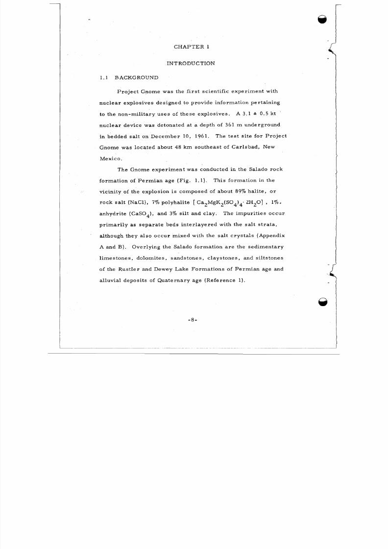
forma t ion of Pe r mi an age (F ig . 1 .1) . This forma t ion in the
vicinity of the explo sion i s co m po se d of ab ou t 89‘10 h al it e, o r
r oc k salt (NaCl) , 770 polyhalite [ Ca2MgK2(S04)4. 2H20] , 1’10,
a nhydr it e ( C a S0 4) , a nd 370 s i l t and c lay.
p r i m a r i l y as s e pa r a t e be ds i n t e r l a ye r e d w ith the s a l t s t r a t a ,
The im pur i t i e s oc c u r
a lthough they a l so occu r mixed wi th the sa l t c ry s ta l s (Appendix
A and B ). Over ly ing the Sa lado forma t ion a r e the s ed im enta ry
l i m e s o n e s , dolomi te s , sands one s , c l a ys one s , a nd s i l t s one s
of the Rus t le r and Dewey Lake Form a t io ns of P e r m ia n age and
a l luvia l depos i t s of Qua te r na ry age (Refe rence 1) .
-8 -
8/8/2019 pne 107 Gnome
http://slidepdf.com/reader/full/pne-107-gnome 11/92
c
-23.8m I I
I-
Iv,
LL
a-
D E W E Y L A K E F O R M A T I O N
85.9m
D R I L LH O L E S
R U S T L E R F O R M A T I ( 3 N
I98 m
S A L A D 0 F O R M A T I O N
Fig . 1 .1 Ver t ica l sec t ion through the Gnome postshot e nv i r on -m e n t .
- 9 -
8/8/2019 pne 107 Gnome
http://slidepdf.com/reader/full/pne-107-gnome 12/92
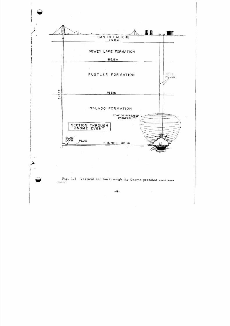
The Gnome device was em place d at the end of a buttonhook-
shaped d r i f t , a dis tan ce of 301 m f ro m the sha f t (F ig . 1 .2 ).
f i r s t 274 m of the dr if t we re str aig ht along a l ine between the
The
shaf t and the device .
to as the "buttonhook" portion.
The r emaind er was cu rved and is r e f e r r e d
The dr i f t was designed so tha t the
buttonhook would close following the detonation and contain the
explosion .
men t we re such tha t mos t of th e dr i f t had to be l ine-of -s ight to the
Requ i r emen t s fo r an asso c ia t ed neu t ron-phys ics expe r i -
d e v i c e . , An evacuated pipe ( the "neut ron p ipe") extended f ro m a
revolving wheel ( the "neutron wheel") through the s tra ig ht port io n
of the dr if t and continued through a dr i l l ho le to the dev ice room .
Backup s t emm ing was p rovided in the d r i f t nea r the sha f t t o
r e s t r i c t v en ti ng i f the c lose- in s temming fa i led .
1.2 OBJECTIVES
The ma jo r object ive of the postsh ot explora t ion pr og ra m was
to provide a defini tion of the e nviro nme nt c re at ed by the detonation
in suppor t of the pr i m ar y object of P roj ec t Gnome:
ef fects <of n underg round nuc l ea r exp los ion in sa l t .
exp erie nce with volcanic tuff and al luvium at the Nevada Te st Si te
had provided a general unders tanding of the in tera ct ion between
nuc le a r exp los ions and rock mate r i a l s .
provided an excel lent tes t of th is un ders tanding, s ince the physical
and chem ica l p roper t i e s of sa l t a r e g rea t ly d i f f e r en t f ro m those of
tuff and alluvium .
To stud y the
Prev ious
An explo sion in sa lt
-10-
8/8/2019 pne 107 Gnome
http://slidepdf.com/reader/full/pne-107-gnome 13/92
CRO SSCUT 2
N WH EL
BUTTO N HOOK
EXPLO RATI O N\
C A V I T Y
BOUNDARYBLAST DO O R
CROSSCUT I
SC A LE
0 IO 20 30 40 50
M E TE R SI : : : : I
Fi g . 1.2 Plan view showing the post-explosion exploration and cavity (shade d) (thefine line drawing indicates the pr e -detonation configuration).
1
8/8/2019 pne 107 Gnome
http://slidepdf.com/reader/full/pne-107-gnome 14/92
Many da-a we re als o obtained perta ining to s om e of the
othe r object ives of the exp erim ent , speci f ica l ly:
1 .2 .1 The Iso topes Pr og ra m: To de te rmin e the feas ib i l it y
of rec overing radioisoto pes produced by a nuc lear exp los ion .
Thi s method would re pr ese n t a s ign if i can t a l t e rna t ive to rea c to r
methods .
designed to produce quant i t ies of useful i sotop es, the mixed f i ss ion
product s made poss ib le a feasibi l i ty s tudy.
Although the device used in Gnome was not specifical ly
1.2.2 The Power Pro gr am : To inves t iga te the feas ib i l i t y
of the me as ure me nt and ext ract i on of hea t deposi ted by the
explosion.
salt mel t ed by the explos ion might be ex t ra c ted and used for
e l e c t r i c a l p o w er .
It had been sug ges ted tha t the hea t of fusion of the
1.2.3 Shock Effects Studies: To subject a va r i e t y of
m i ne ra l and o rgan i c s am p l e s t o a r ange of shock p r e s su re s
produced by the explos ion in o r de r to de te rmine the e f fec t s of
t he explosion (in t e r m s of phase t rans i t ions , p rop er ty changes ,
e t c . ) on the sam ples .
The purpose of re - en t ry dr i l l ing f ro m the sur fac e was to
provide rad ioac t ive sa mple s fo r y i e ld de te rmina t ion ; to enable
mea sur eme nt s concerned with the power feas ib i li t y s tud ies ; and
to prov ide p re l im inar y def ini t ion of the envi ronment c rea ted .
-12-
8/8/2019 pne 107 Gnome
http://slidepdf.com/reader/full/pne-107-gnome 15/92
1.3 EXPLORATION PHASES
Pos t -de tona t ion explora t ion cons i s ted of: 1 ) examina t ion
of the s ur fa ce fac i l i t i e s and the ground su r fac e ove r the working
point" ' (R efe ren ce 2); 2 ) exam inatio n of the sh aft and the bottom
sta t ion s i x days following the de tonat ion (R efer enc e 2); 3)
dr i l l ing f ro m the sur face in to the cavi ty reg ion dur ing the pe r iod
f r om D e c e m be r 11 , 1961 t o J a nua r y 18 , 1 9 6 2 ; 4) underground
mining and dr i l l ing explora t ion, inc luding r e -en t ry in to the emp lace -
.b
r e - e n t r y
m e n t d r i f t , r e c ov e r y o f s hocke d s a m ple s and i n s t r um e n t s , e n t r y
into the cavi ty produced by the explos ion and gener a l de f in i t ion ,
by d i rec t obse r va t ion , of the pos t shot envi ronment . Explora t ion
was com ple te by the end of Sep tem ber , 1963.
the work accompl i shed dur ing phases 3 and 4.
T h i s r e p o r t c o v e r s
1 .4 OBSERVATIONS IMMEDIATELY FOLLOWING THE EXPLOSION
L e ss than one minute following the explos ion, radia t io n was
de tec ted at the blas t door near the bot tom of the sha f t ( F i g . 1 . 2 ) by
rem ot e -a rea rad ia t ion mo ni to r s . No rad ia t ion was de tec ted at the
sha f t co l la r un t il th ree m inutes and for ty seconds a f te r the de tona tion .
At approxima te ly seven minutes a f te r z e ro t ime , a g r a y s m o k e , s t e a m ,
and a ssoc ia ted rad ioac t iv i ty sur ged f ro m the sha f t opening . By e leven
minu tes fol lowing the explos ion, copious quant i t ies of s te am issu ed
f r om both sha f t and vent i l at ion l ines . A large f low cont inued for!
~~
.
The loca t ion of the nuclear device .
-13-
8/8/2019 pne 107 Gnome
http://slidepdf.com/reader/full/pne-107-gnome 16/92
about th i r ty minutes be fore gradua l ly dec reas in g . A small flow
was st i l l detected through the following day. The radioact ive
e lem ents tha t vented through the sh af t we re vola t i le and noble
gases (Refe rence 3 ) .
The unexpected venting of s t ea m and associa t ed radio -
ac t ive g ase s led to an addi tional objec t ive for the explora t ion
p r o g r a m - the deter min atio n of the cau se and na tur e of venting.
The Gnome event was moni to red by geophone a rr ay s f ro m
shot t ime unti l the shot envi ronment was pene t ra ted by re - en t ry
dr i l l ing .
rock movement las ted for th ree minu tes following the explos ion
The geophone rec or ds indica ted tha t noise produ ced by
and were v e ry inf requent a f te r tha t t ime .
n
- 14-
8/8/2019 pne 107 Gnome
http://slidepdf.com/reader/full/pne-107-gnome 17/92
CHAPTER 2
THE CAVITY ENVIRONMENT
2.1 GENERAL
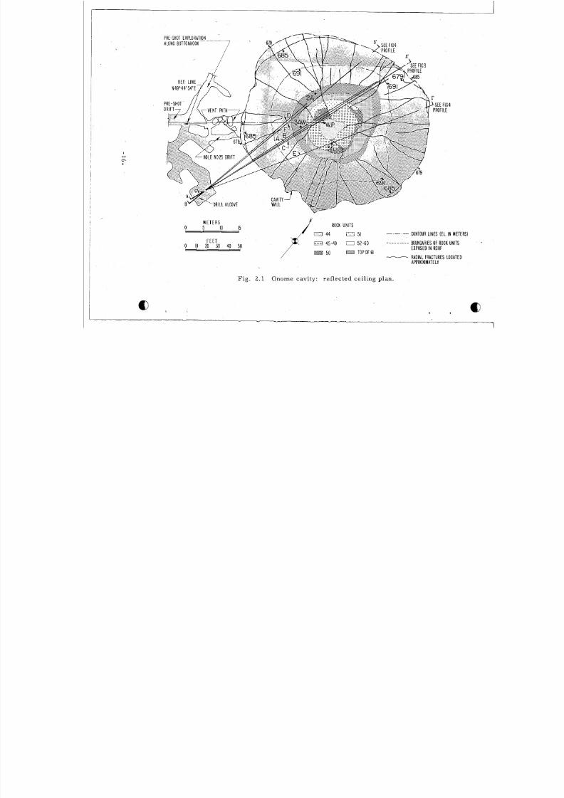
P o s t sh o t e x p l or a ti o n s t a r t e d f i r s t f r o m t he su r f a c e an d
then w a s accompl ished by dr i l l ing and dr i f t excavat ion underground
( s e e F i g . 2.1) .
On May 17, 1962, only f ive months af te r the explosion ,
excava tion along p res ho t d r i l l ho le #25 fo r the purpose o f r ec ov er -
ing shocked sam ples r esu l t ed in ac tua l pe r sonne l e n t r y in to the
cavi ty .
photographic documentat ion and a minim al t r i angu la t ion su rv ey to
define i ts s i ze and sha pe . (F ig . 2 .1 ) . A t tha t t im e , the air t e m p e r a -
t u r e w a s 50°C nea r the cav i ty en t r anc e , t he r e l a t ive humid ity w a s
60-7070, nd the r ad ia t ion l e ve l s va r i ed f r om p lace - to -p lace , but
w e r e r a r e l y in e x c e s s of 20 mR/hr .
p r e h e n s i v e t e m p e r a t u r e su r v e y in d i c a te d a var i a t ion be tween 50
and 57°C within the cavity.
Th i s made poss ib le d i r ec t obse rva t ion of the cav i ty in t e r io r ,
One month l a t e r a m o r e c o m -
I t shou ld be no ted tha t fo r sev era l
weeks pr ior to and.fo l lowing cavi ty ent ry , fans located in dr i l l
ho les f r o m t he su r f ace in to the cav i ty had f lushed sev era l mi ll ion
cubic me te r s of a i r t h rough th i s env i ronment .
-15-
8/8/2019 pne 107 Gnome
http://slidepdf.com/reader/full/pne-107-gnome 18/92
I
Q I
M E T E R S0 5 IO 15
F E E T0 IO 20 30 40 50
F i g .
R O C K U N I T S
LNL134 D 1 C O N T O U R L I N ES (EL . I N M ET ER S)
BOUNDARIES OF R O C K U N I T SE X P O S E D I N R O O F- AD I AL F R AC T U R ES LO C AT EDAPPR O XI M AT ELY
- - - - - - - - -EX 4 5 - 4 9 El 2 - 6 0
T O P O F 6 15 0
2.1 Gnome cavi ty: re f lec ted ce i l ing plan.
8/8/2019 pne 107 Gnome
http://slidepdf.com/reader/full/pne-107-gnome 19/92
2 .2 CAVITY VOLUME AND SHAPE
A n es t im ate of the tot a l void volume produ ced by the explos ion
was ma de , us ing a combinat ion of th ree :points f r o m dr i l l ho les
penetra t ing the top of the cavi ty , photographic guides for ex t rapo-
la t ion f r om surv ey cont ro l with in the cavi ty , and und- rground dr i l l
holes which def ined the cavi ty be low the working point in 10 pl ace s .
This volume was ca lcula ted to be 27,200 cubic me te rs (Appendix D)
and i s in ve ry good ag reem ent with a m e a s u r e m e n t m a d e by
pr e s s u r i z ing t he c a v i ty wi th c o m p r e s s e d ai r . A known volu me of
a i r at a known pr es su re was in t roduced in to the cavi ty . F r o m
these m eas ur em ent s the cavi ty volume was ca lcu la ted to be
28,000 f 2,800 cubic m e t e r s ( J . T r a c y , L R L - ve r ba l c om m u-
nica t ion) .
The total void volume of 27,200 cubic me te r s is equivalent
to a sph e re wi th a r a d ius of 1 8.7 A e t e r s . T he ca v it y i s a s y m m e t r i c ,
how e ve r , because of aniso t ropic re s i s tan ce to cavity expans ion ,
implos ion of the cavity wa l l s , and pa r t i a l ce i l ing co l lapse ( see
discuss ion in Chapte r 3 ) .
has an ave rage rad ius of 17.4 m i n the l ow e r por t i on ( m e a s u r e d
The cavity shown in F i g s . 2.2 and 2.3
f r o m the working poin t to the boundary of r ad ioac t ive me l t ) ; an
average radius of 24.4 m in the equ ato r ia l plane; and an a ve r a ge
r a d i u s of 22.9 m in the uppe r po r t ion (m eas ur ed f r om the working
point to the rock-void interfa ce) . The shape of the ce i l ing of the
cavi ty ind ica te s tha t the ma jor pre - shot weaknesses i n the
rock , the bedding p lanes or ho r izonta l boundar ie s be tween
-17-
8/8/2019 pne 107 Gnome
http://slidepdf.com/reader/full/pne-107-gnome 20/92
G N O M E C A V I T Y C R O S S S E C T I O N 3 k t
1 \ 1SLIGHTLY RADIOACTIVE MELTIN J E C T E D IN T O F IS S U R E S
---- FAULT
- - --:--:EDDING CONTACTS--
c-se=e>RACTURE ZONES
CA VlTY VOID
' .
0L0
F i g . 2 . 2 Cavity profi le A-A' ( s e e F i g , 2.1 for plan view).
-18-
8/8/2019 pne 107 Gnome
http://slidepdf.com/reader/full/pne-107-gnome 21/92
C A V I T Y V O D
R U B B L E P I L E
- A & -
~ P R E S H O TO C A T I O N
OF S T R A T A
C A V I T Y PROFILE C - C '
S C A L E
0
M E T E R S
C A V I T Y V O D
M E L T D I S T R I BU T I O N , H O L E *F "
ESH OT LOC A TION
- - ---h-
C A V I T Y PROFILE B-B'
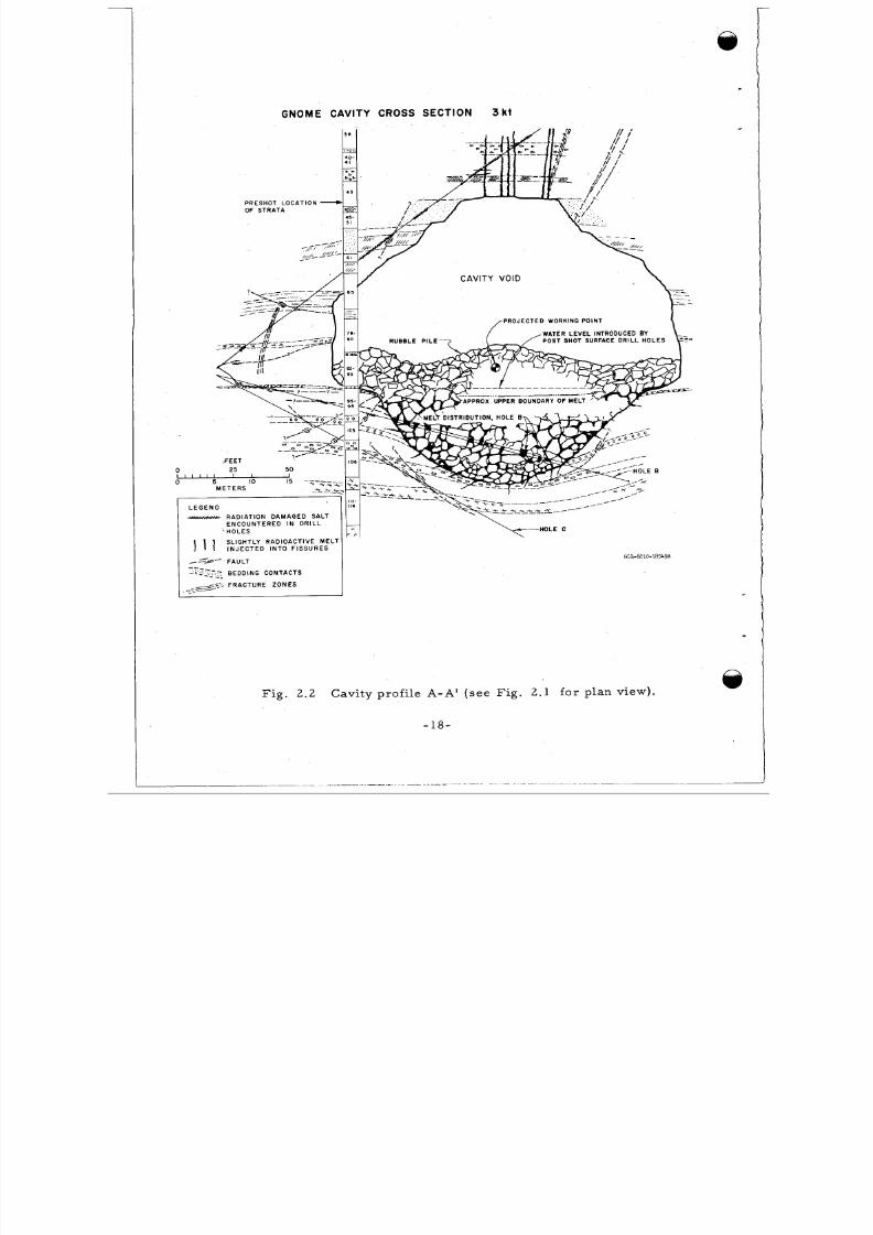
F i g . 2 .3 Cavi ty profi le s B - B ' and C - C ' ( s e e F ig . 2.1 for plan
view) .
-19-
8/8/2019 pne 107 Gnome
http://slidepdf.com/reader/full/pne-107-gnome 22/92
rock uni ts , somewhat control led the extent of col l apse . I t is v e r y
l ike ly tha t l e s s co l lapse would have oc cu r re d i f these weaknesses
had not exis ted.
The m os t s i gn i fi c an t de pa r tu r e f r o m s phe r i c a l s ym m e t r y i s
a gi rd le of ro ck about 9 m high surrounding the equato r ia l region
of the cavity.
ing point than rock n ea re r the base o r top of the cavi ty.
This reg ion moved rad ia l ly fur t he r f ro m the work-
The
deve lopment of th i s a sy mm etr y w a s mo st l ike ly cont ro l led by
bedding plane weak nes ses and thin hor izonta l c lay s t ra ta tha t
sep a ra te d mo re compe tent beds of salt and polyhal i te . The expla-
nation of this bulge i s d i s c us s e d f u r t he r i n the s e c t i ons on pe r m a -
ne n t d i s p l a c e m e n t s and e a r t h de f o r m a t ion . The cav ity would be
m or e s ym m e t r i c a l a bou t a ve r t i c a l a x i s pa s s ing t h rough a point
about 4 m no rth eas t of the working point ra t he r than through the
working point ( the cen ter of the nu cle ar de vice ) .
me nt of the effec t ive cen ter of en erg y ma y be due to the sh ape
Th i s d i s p l a c e -
of the cha mb er in which the device was de tonated, r e s u l t i ng i n
the ini t ia l dis t r ibut io n of the explos ion ene rg y as a c y l i nd r i c a l
s ou r c e r a the r t ha n a s phe r i c a l one.
2 .3 RUBBLE AND ASSOCIATED RADIOACTIVE MELT
The m a ss of rock mel t ed by the explos ion, bas ed on the
a na lys i s of o r e r e c ove r e d f r o m d r i l l ho l e s , i s e s t im a te d t o be(
6 6about 3.2 X 10 kg, eq uivale nt to about 10 kg pe r kiloton of yield.
- 2 0 -
8/8/2019 pne 107 Gnome
http://slidepdf.com/reader/full/pne-107-gnome 23/92
This mass com par es favorably wi th the expec ted mass vapor ized
and me lte d of about 1 .4 X 10 This predic t ion waskg pe r ki loton.
based on the a ssum ption tha t 41% of the explos ive e ner gy is ut i l ized
in me l t ing the rock (Refe rence 4).
mix ed with about 11.6 X 10
imploded , dec repi ta ted , o r f e l l in to the cavi ty ' ea r ly dur ing the
f i r s t few seco nd s following the explosion.
The me l t became in t ima te ly
6kg of ro ck , mu ch of which w a s probably
6An es t im a ted 13.6 X 10
kg of rock co l lapsed la te r f r om the upper hem isphe r e and b lank-
e ted the reg ion conta in ing the rad ioac t ive m e l t b rec c ia at the cavi ty
base (Appendix D).
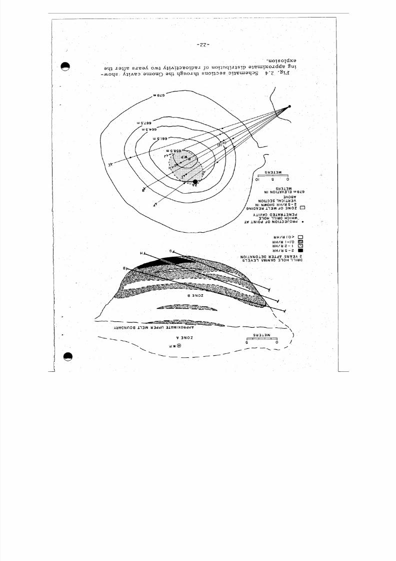
The region denoted as Zone B i n F ig . 2.4 can gene ra l ly be
d e s c ri b e d a s a r oc k - m e l t b r e c c i a i n w h ic h the m e l t f o r m s m uc h
of the ma t r ix be tween the la rg e r rock f ragmen ts ( the range of
pa r t i c l e d i a m e te r s is es t i mat ed to be about 15 c m to 3m) . The
m e l t i t s e l f e ngu l fs s m a l l e r r oc k f r a gm e n t s t ha t r ange i n d i a m e te r
f r o m a f r a c t i o n of a c e n t i m e t e r to a f e w c e n t i m e t e r s . T h e d e g r e e
of d ilu tion of sam ples of the me l t va r ie s g rea t ly f r om a lmo s t no
r oc k f r a gm e n t s t o as m uc h as 30 o r 40 pe r c e n t .
Becau se m uch of this zone is typica l ly a mix tur e of rock
f ragments cemented toge the r by the me l t matr ix , it i s l ike ly
tha t th i s m a te r ia l would be se l f- suppor ting i f ac tua l mining r e -
e n t r y w e r e n e c e s s a r y .
boundary where the concentra t ion of melt i s the highes t .
l ike ly , a l ib era l amount of rock s upp or t would be ne ces sar y.
This is e s pe c i a l l y t r u e ne a r t he c a v it y
Most
-21-
8/8/2019 pne 107 Gnome
http://slidepdf.com/reader/full/pne-107-gnome 24/92
e
- z z -
rU 3 1 3 WN I N O l l V A 3 1 3 u8L9
3 A O E VN 0 1 1 3 3 S l V 3 1 1 U 3 A
N I N M O H S UH/M E - 29 N l C I V 3 t l 1 1 3 W d 0 3 N O Z 0
A l l A V 3 Q 3 1 W k l 1 3 N 3 d
1 V l N l O d dQ N 0 1 1 3 3 r O t l dOH i i i k l a H ~ I H M .
t l H / t l I ' O > 0
H H / U 1-1'0t l H / U Z - l
U H / U G - Z
N O l l V N 0 1 3 0 t l 3 1 d V S U V 3 A Z
s i 3 ~ 3 i ww v o 3 - 1 0 ~i i t l a
\
Y 1
----\\
U V ' a N n 0 8 1 1 3 W U
8/8/2019 pne 107 Gnome
http://slidepdf.com/reader/full/pne-107-gnome 25/92
This ma te r i a l was suff ic ient ly se l f -supp or t ing, howev er , tha t the
dr i l l ho le s rema ined open without cas ing .
The rubble in Zone A, Fig . 2.4, above the zone containing
radioac t ive me l t is essent ia l ly a loose pi le of rock f rag me nts and
i s no t se l f -suppor ting . Dur ing re -e n t r y dr i l l ing the hole s caved
in this region, caus ing conside rable dif ficul ty. In this zone , the
pa r t i c le - s ize va r ia t ion ' can be approxima ted with reasonab le '
acc ura cy by d i re c t obse rva t ion of the rubble s ur fac e exposed at
the ba se of the cav ity void.
l a r ge , va r y ing f r om c r us he d r oc k f r agm e n t s l e s s t han 1 c m a c r o s s
to l a rg e b locks as l a r g e as 7 m a c r o s s t he m a x im u m d im e ns ion .
The range in. pa r t i c l e s i z e is e x t r e m e l y
,
Blocks exceeding 2 m ac ro ss account for l e s s than 10 pe rce nt of
the rubble and the ave rage pa r t i c le d iam e te r i s about 75 cm .
The explos ion l ibera ted at l e a s t 5 X l o 4 kg of wat er f r om
kg o r
kg of r oc k
4the vapor ized and mel t ed rock and an addit ional 17 X 10
wa ter could have been l ibera te d f r o m the 11.6 X 10
that ca me fr om the cavi ty wal l and was mix ed with the me l t .
M. Nathans (Ref eren ce 5 ) c a l cu l a te d f r om the t r i t i um c onc e n t r a -
t ion in the vented s te am tha t as much as 4 X 10
6
5kg of water
might have .been l ibe ra ted f ro m the rock . Had the r e not been
venting to tap off much of thi s wa te r, i t would have eventually
condensed and collected in the voids of the rubble -at the base of
the cavi ty. As it was , the wa te r l eve l in the rubble was at an
elevat ion of 673 m , o r 2.1 m below the working point. Mos t of
- 2 3 -
8/8/2019 pne 107 Gnome
http://slidepdf.com/reader/full/pne-107-gnome 26/92
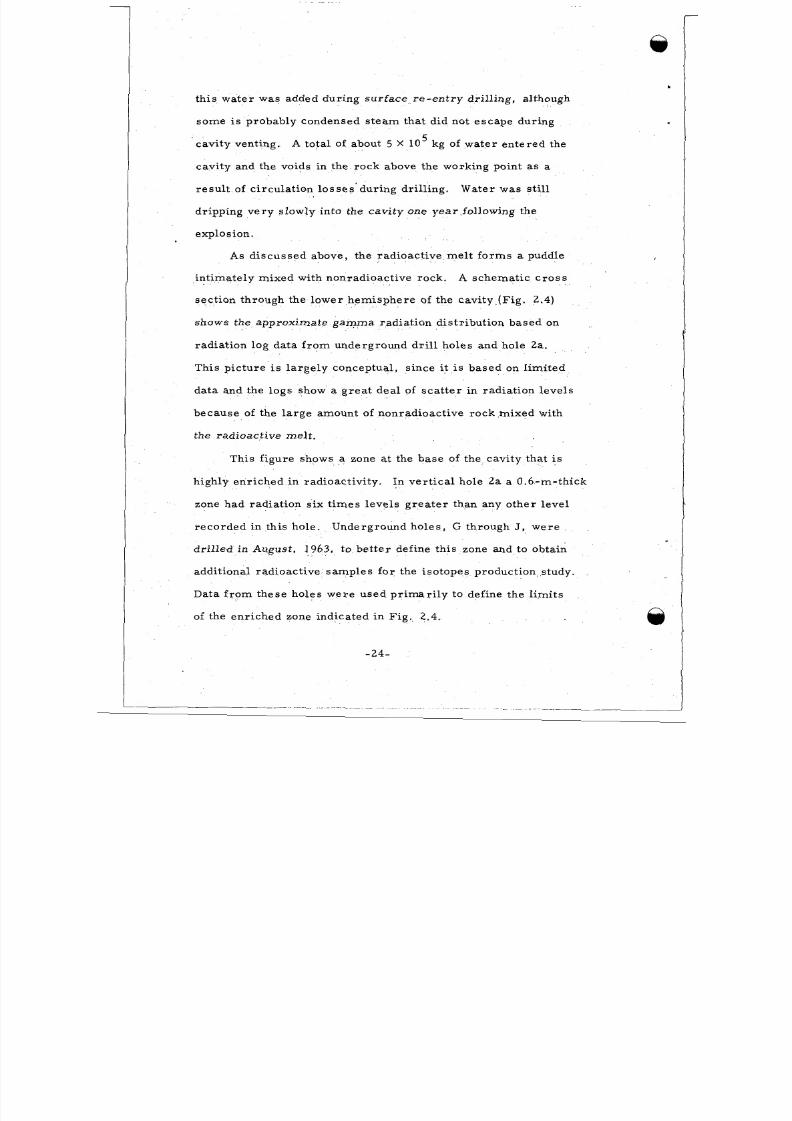
th is water was added dur ing sur fac e re- en t ry dr i l l ing , a lthough
so m e i s probably condensed s te am that d id not escap e dur ing
cavity venting.
cavity and the voids in the rock above the working point as a
5
A to ta l of about 5 X 10 kg of wate r en ter ed the
res ul t of c i rcu la t ion loss es ' dur ing dr i l l ing . Water was s t i l l
dr ipping ve ry slowly into the cav ity one ye a r fol lowing the
explosion .
As d i scuss ed above , the r ad ioac t ive m el t f o rm s a puddle
A s c h e m a ti c c r o s s
,
in t imate ly mixe d wi th nonradioact ive rock.
sect ion through the lower hem isph ere of the cavi ty- (F ig . 2 .4)
shows the approximate gamma radia t ion d is t r ibut ion based on
radia t ion log data f ro m underground d r i l l holes and hole 2a .
Th i s p i c tu re i s l a rg e ly concep tua l , s ince it i s based on l imi t ed
data and the logs show a gre a t dea l of sca t t e r i n r ad ia t ion l eve l s
bec aus e of the la rg e amount of nonrad ioactive rock mixed with
the radioact ive mel t .
This f igure shows a zone at the bas e of the cavity that i s
highly enr ic hed in radioact iv i ty . In ver t ic a l hole 2a a 0.6-m-th ick
zone had r ad ia tion s ix t im es l eve l s g rea te r than any o the r l eve l
r ecorded in th i s ho le .
dr i l le d in August , 1963, to be t t er def ine this zone and to obtain
addi tional radioact ive sam ples f or the i so topes product ion s tudy.
Da ta f ro m these ho les w ere used p r im ar i ly to de fine the l imits
of the en ric he d zone indicated in Fig. 2.4.
Underground holes , G through J , w e r e
-24-
8/8/2019 pne 107 Gnome
http://slidepdf.com/reader/full/pne-107-gnome 27/92
o r d e r t o d e t e r m i n e m e t h o ds of p r o c e s s i n g t h i s " o r e " f o r e l e m e n t s
t h a t a r e c h e m i c a l ly similar to the ac t in ides .
( R e f e r e n c e 5) cover s the de ta i l s of th is s tudy.
mined tha t a lmos t all of the f i ss ion products (o th er than the ga seous
o r vo la t i le o nes ) r em ain wi th the sal t i m p u r i t i e s wh en s a m p l e s a r e
e i t h e r d i sso l v ed i n w a t e r o r r e m e l t e d t o s e p a r a t e t he N a C l f r o m
t he o t h e r i m p u r i t i e s .
mine wi th which chem ica l sp ec ie s the d i f f e r en t r ad io -e l emen t s
a r e a s s o c i a te d .
A r e p o r t b y M. Nathans
It h a s b e e n d e t e r -
P a r t of the scope of th is s tudy i s t o d e t e r -
I t i s i n t e r es t ing to no te that t he min era l o l iv ine , speci f ica l ly
f o r s t e r i t e (M g S i 0 ) , makes up a s igni f icant por t ion of t h e w a t e r -2 4
i n so lub le f r ac t ion of se ve ra l sam ples .
p res ho t in the rock .
Th i s m i n e r a l d id no t o c c u r
The ma jo r sou rce of magnes ium was the
mi ne ra l po lyha li te [ Ca2MgK2(S0 ) * 2H20] . M a g n e s i u m a l so4 4
o c c u r s i n the c lay m ine ra l s and in t r a c e qua n t i t i e s of m a g n e s i t e
(MgC03). S i li c a o c c u r s p r i m a r i r t z p a r t i c l e s
and wi th the c l ay mi ne ra
of o th er chemica l react io
the r ad ioac t iv i ty f r ac t ion
e '5 a l s o d e s c r i b e s a v a r i e t y
se ve ra l compounds and1 .
d w i th t h e se sp e c i e s .
Ex am ples of the so l id i f ied s,alt me l t a r e shown in F ig . 2 .5.
Sample B-21H i s on ly s l igh t ly ves i cu la t ed . It w a s t ak e n f r o m
about 2 m f r o m t he fa r cavi ty boundary in dr i l l hole B (Fig . 2. 2),
and conta ins a l a rge amoun t of r o c k f r a g m e n t s , p r e su m a b l y blow n
-25-
8/8/2019 pne 107 Gnome
http://slidepdf.com/reader/full/pne-107-gnome 28/92
J
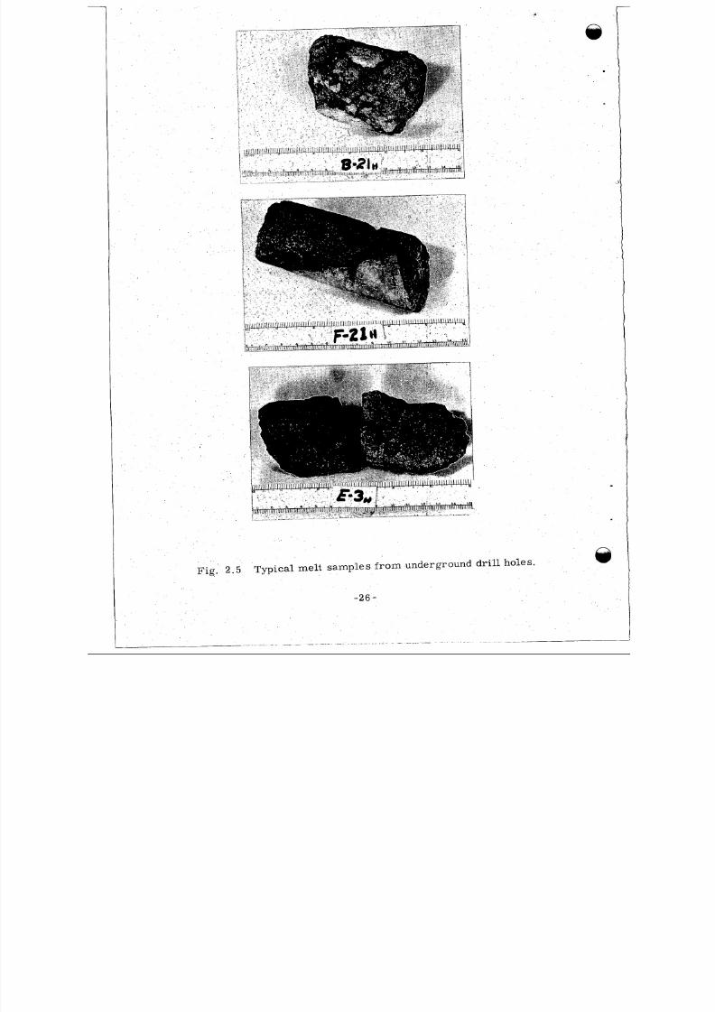
Fig. 2 . 5 Typical melt samples f r om underground d r i l l holes,
8/8/2019 pne 107 Gnome
http://slidepdf.com/reader/full/pne-107-gnome 29/92
off the ca vit y wal ls .
bec aus e of the sup erh eat of the me l t .
Some of the f ra gm en ts underwent fus ion
Sample F-21H i s f r o m
dr i l l ho le F (F ig , 2 .3) ne a r the cavi ty edge . The me l t in contac t
with the unfused salt f o r m s a dense band in co nt ra s t wi th the
ve s i c u l a r m e l t on t he o the r s i de of the band. It i s i n t e rp r e t ed
tha t fol lowing cavi ty growth the roc k bounding the cavi ty broke
up and impl oded , a l lowing the sa l t m el t to invade openings tha t
r e s u l t e d .
form ing unves icu la ted me l t at the contac t .
c i r c u m s t a n c e s , it would be exp ec ted tha t th i s ch i l led bo rde r
would be gradat i onal , but at Gnome it i s qu it e pos s ib l e t ha t
The newly exposed co lde r rock quenched the me l t ,
U nde r no r m a l
w he n ve n ti ng oc c u r r e d , t he c a v it y p r e s s u r e d r oppe d r a the r
abrup t ly, caus ing violent out-gass ing of the me l t . This sudden
out-g ass ing , which was c lo se ly fol lowed by sol idif ica t ion of
the me l t , p roduced ves icu la t ion . Sample E-3H was taken f ro m
d r i l l hole E ne a r the ce nt ra l por t ion of the cavi ty about 25 f t
above the cavi ty bot tom (F ig . 2 .3) . This melt c ool ed m o r e
s lowly than mo s t of the me l t obse rv ed and deve loped la r ge
c r y s t a l l i t e s - up to 4 mm in d ia me t e r . Mos t of the me l t
s o l i d if i e d ra p id ly a nd i s f i ne - g r a ine d - l e s s t h an 1 m m .
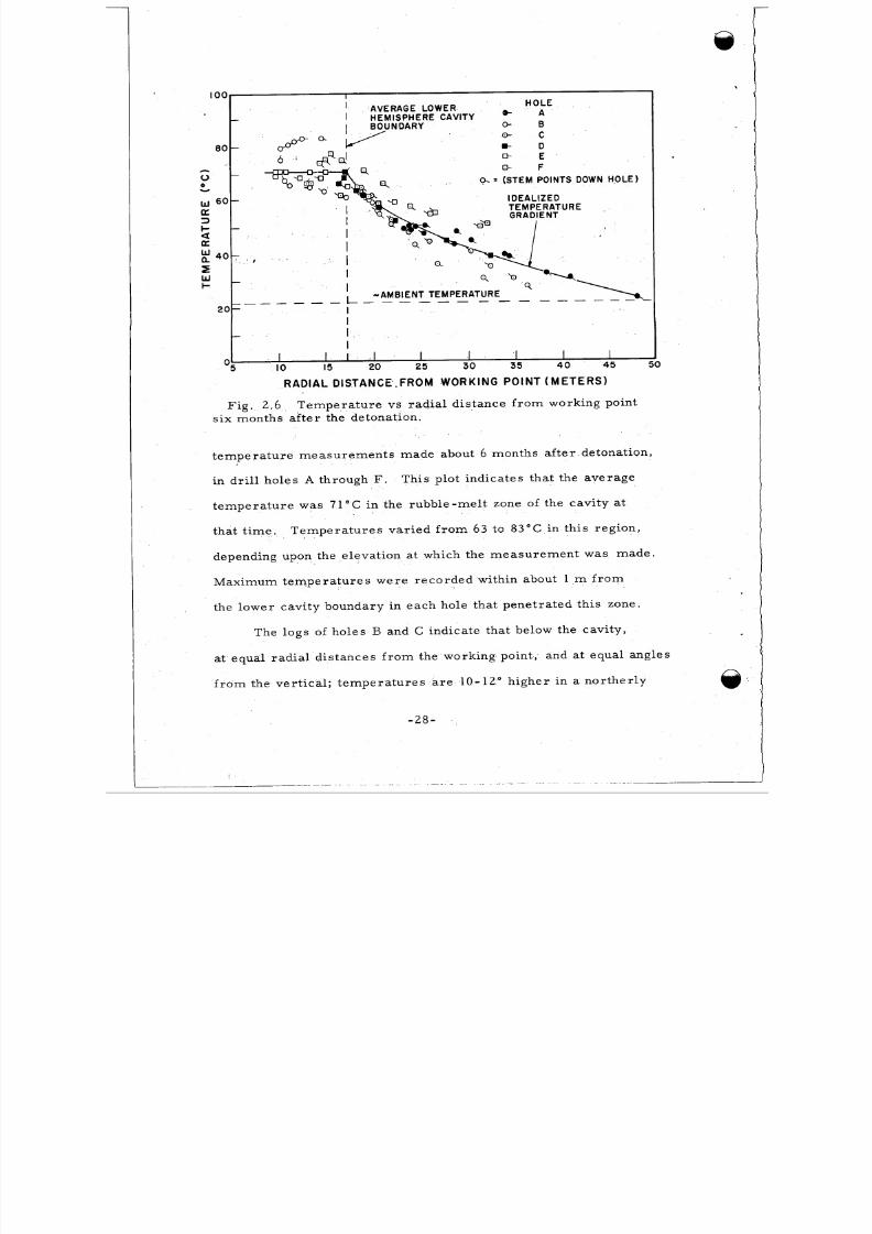
2.4 ROCK TEMPERATURES
A p lot of t e m pe r a tu r e ve r s us r a d i a l d i s t a nce f r om the w or k -
ing point i s shown in Fig. 2.6. Data poin ts shown wer e taken f r o m
- 2 7 -
8/8/2019 pne 107 Gnome
http://slidepdf.com/reader/full/pne-107-gnome 30/92
I O 0 I
H O L Ee- A
0- C
m- D
E- EE- F
' AVERAGE LOWER- I H E M I S P H E R E C A V I T Y
BOUNDARY 0- B
80 - OD""" v6 * +
-
0
0 oc = (STEM POINTS DOWN HOLE)Y
I D E A L I Z E Dw 60-a
aa
n 4 0 - . ,5W -+
3
I-
w
-
II -AMBIENT TEMPERATURE
20- II
I
_ _ _ _ _ _ _ L _ _ _ _ _ _ - - - - - - - -
-I
I I I I I II O 15 20 25 30 35 4 0 45 I
RADIAL DISTANCE'.FROM WORKING P OINT (M E TE RS )
F i g , 2.6 T em p era t u re v s r ad i a l d i s tance f rom w orki ng po in t
s ix months a i t e r t he de tona t ion .
t e m p e r a t u r e m e a s u r e m e n t s m a d e a bo ut 6 months a f t e r de tona tion ,
in d r i l l ho les A through F. This p lo t i nd ica tes tha t t he averag e
tem pe ra tur e was 71°C in the r ubble-m el t zone of the cav i ty at
t ha t t i m e .
depending upon the elevat ion at which the me as ur em en t was mad e.
T em pera t u re s va r i ed f r om 63 t o 83°C i n t h i s r eg i on ,
Max im um t em pe ra t u r e s w e re r eco rd ed wi th in about 1 m f r o m
the lower cav i ty boundary in eac h hole tha t pene t ra t ed th i s zone.
The logs of holes B and C indicate that below the cavity,
at equal rad ia l d i s t ances f rom the working point , and at equal angles
f r om t he ve r t i c a l ; t em pera t u re s a re 10-12" h i ghe r in a nor t he r l y
-28-
8/8/2019 pne 107 Gnome
http://slidepdf.com/reader/full/pne-107-gnome 31/92
dire ct ion than in the sou therly . T h is a s y m m e t r y is consis ten t wi th
the asymm et r i c a l posi t ion of the zone of highly- rad ioac t ive mel t
desc r i be d p rev i ous ly .
- 2 9 -
8/8/2019 pne 107 Gnome
http://slidepdf.com/reader/full/pne-107-gnome 32/92
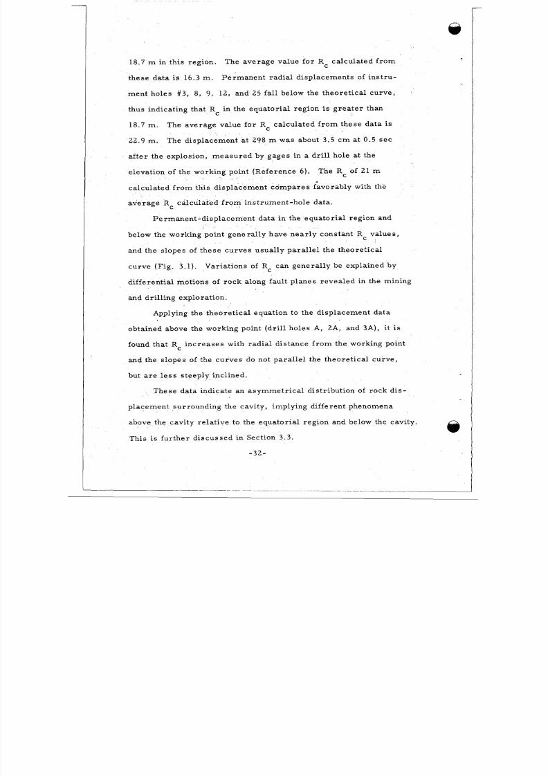
3 . 1
CHAPTER 3
PERMANENT DISPLACEMENTS
GENERAL
Q
Displacem ent of the ma ter ia l surro unding the Gnome explos ion
ha s be e n m e a s u r e d l a t e r a l l y at a distance of 298 m by gages in a
dr i l l ho le (R efe rence 6 ) , and the perm anen t displac ement of the
sur face o ve r the working point i s known by sur vey s (Ref eren ce 7 ) .
In addi t ion , p e rmanent rad ia l d i sp lacements have been de te rmined
f r om presh ot and pos t shot pos i tions of r oc k s t r a t a a nd o th e r m a r k e r s
such a s i n s t r um e n t ho l e s .
Pre sho t e leva t ions of beds were obta ined f r om the USGS l i tho-
logic log (Refere nce 8) and tunnel map (Reference 1) .
pos i t ions were de te rmined f ro m geophys ica l logs of the ve r t i ca l ho le s
Pos t s ho t
a nd f r om c o r e f r o m the unde rg r ound i ncl ine d d r i l l ho l e s. P r e s h o t
and postsho t pos i t ions of beds a r e ge nera l ly known withinf
0.3 m.
The loca t ions of in s t r um ent holes branching off f ro m the main dr i f t
wer e a ccur a te ly survey ed be fore and a f te r the de tona tion .
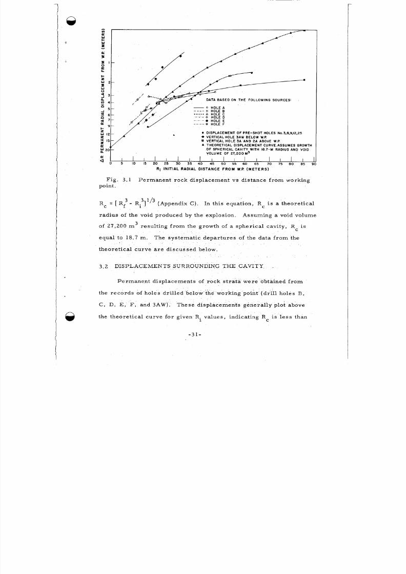
F i g u r e 3 . 1 i s a plot of the perma nen t di splac emen t da t a obta ined
by post shot underground explo ra t ion. Ri - the preshot r ad ia l d i s tance
2of a given point f ro m the working point - is plot ted ag ains t 1/ (R -R ) ,
f i
w he r e R is the cor re sponding pos t shot r ad ia l d i s tance f ro m the work-f
ing point.
the plck and a theore t ica l curve drawn based on the re la t ionship
For convenience , a sca le showing va lues fo r (R -R . ) i s onf 1
\
-30-
8/8/2019 pne 107 Gnome
http://slidepdf.com/reader/full/pne-107-gnome 33/92
-)
WcW
I
a
-
/ -
DATA BASED ON TH E FOLLOWING SOURCES:
I-2w 2 -IW0
4 3 -n4 4 -n
n4 7 -a
5 -J
5 6 -
9-c
DISPLA CEME NT OF PRE-SHOT HOLES N0.3,8.9,12,25
+ VERTICAL HOLE 3 A W BELOW W.P.VERTICAL HOLE 3 A AND 2A ABOVE W.P.
ATHEORETICAL DISPLACEMENT CURVE.ASSUMES GROWTHOF SPHERICAL CAVITY WITH 18.7-M RADIUS AND VOIDVOLUME OF 27 ,200 M3
2 0 -
E
a0 L /o 115 ,b 2: do 315 ,o : do 25 ,b 6: j o 715 ,b 8: J
R i INITIAL RADIAL DISTANCE F R O M W.P. ( M E T E R S )
Fig , 3 .1 Pe r m a ne n t r oc k d i s p l a ce m e n t v s d i s t a nce f r o m w ork ing
point ,
Rc = [ Rf3 - Rf]1/3 (Appendix C) . In this equat ion, R i s a t he o r e t i c a lC
rad ius of the void produce d by the explos ion.
of 2 7 , 2 0 0 m
equa l to 18.7 m .
t he o r e t i c a l c u r ve a r e d i s c us s e d below .
Assuming a void volume
3re su l t ing f ro m the growth of a s phe r i c a l c a v i t y , R c i s
T he s y s t e m a t i c d e p a r t u r e s of t he da t a f r o m the
3 . 2 DISPLACEMENTS SURROUNDING THE CAVITY,
Pe r m a ne n t d i s p l a c e m e n t s of r o c k s t ra ta w e r e ob t ained f r om
the r eco rd s of ho le s dr i l l ed below the working poin t (d r i l l ho le s B ,
C , D, E , F , and 3 AW ) . The s e d i s p l a c e m e n t s ge ne r a l l y p lo t a bove
the th eore t ica l curve f or g iven R. va lues , indica t ing R i s l e s s t h an1 C
-31-
8/8/2019 pne 107 Gnome
http://slidepdf.com/reader/full/pne-107-gnome 34/92
18.7 m in th i s r eg ion . The averag e va lue fo r R ca lcu la ted f ro mC
these da ta i s 16.3 m . Perm anen t rad ia l d i sp lacements of ins t ru-
ment hole s #3 , 8, 9, 12, and 25 fall below the theore t ica l curve ,
thus indicating that Rc in the equ ator ial re gion is gr e a t e r t ha n
18.7 m .
22.9 m .
a f te r the explos ion , m eas ure d by gages in a dr i l l ho le at the
The ave rage va lue for Rc ca lcu la ted f ro m these d a ta is
The displacement at 298 m was about 3.5 cm at 0.5 s e c
elevation of the working point (R efere nce 6 ) . The Rc of 21 m
ca lcula ted f r o m th i s d i sp lacement com pare s favorably wi th the
ave rage R ca lcu la ted f ro m ins t rument -hole da ta .C
Perman ent -d i sp lace ment da ta in the equa tor ia l r eg ion and
below the working point gene ra l ly have nea r l y constant R C va lue s ,
and the s lopes of these curv es usua l ly pa ra l le l the theore t ica l
curve (F ig . 3 .1) .
di f ferent ia l motions of rock a long faul t planes reve aled in the mining
and dr i l l ing explora t ion.
Var iatio ns of Rc can gen era lly be explain ed by
Applying the theor e t ica l equat ion to the displacem ent da ta
obtained above the working point (d ri l l hol es A, 2A, and 3A), it i s
found that R inc rea ses with rad ia l d i s tance f ro m the working pointC
and the s lop es of the curv es do not par a l l e l the theo re t ica l cur ve ,
but a r e l e s s s teeply inc l ined .
These da ta ind ica te an a sym metr ica l d i s t r ibu t ion of rock d i s -
placeme nt surro undin g the cavi ty, implying dif ferent phenomena
above the cavi ty re la t ive to the eq uato r ia l region and below the cavi ty.
This i s fur th e r d i scu ssed in Sec t ion 3 .3 .
-32-
8/8/2019 pne 107 Gnome
http://slidepdf.com/reader/full/pne-107-gnome 35/92
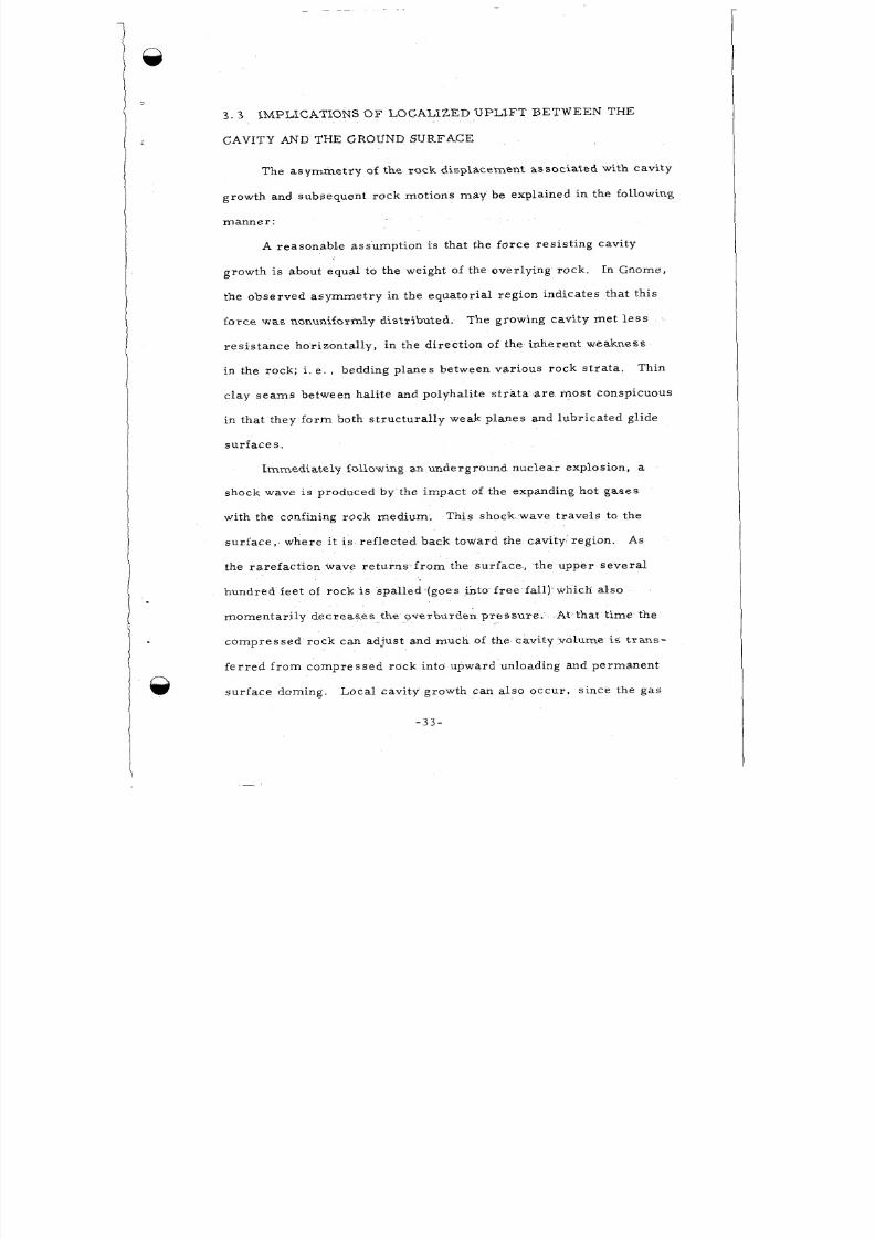
3 . 3
CAVITY AND THE GROUND SURFACE
IMPLICATIONS O F LOCALIZED U PLIF T BETWEEN THE
The asym me try of the roc k d isplacemen t asso cia ted wi th cavi ty
growth and subsequent roc k motions m a y be explaine d in the fol lowing
m a n n e r :
A r easonab le assumpt ion i s t ha t t he fo rce r e s i s t ing cavi ty
growth is about equal to the weight of the overlying r ock .
the obse rved a sym me t ry in the equa to r i a l r eg ion ind ica tes tha t t h i s
forc e was nonuniformly d is t r ib uted . The growing cavi ty me t le ss
res is ta nce ho r izonta l ly , in the d i rect ion of the inhere nt weaknes s
in the rock; i . e . , bedding p lanes between var ious rock s t ra ta .
In Gnome,
Thin
c lay s ea ms be tween ha li t e and po lyhal it e s t r a t a a r e mos t consp icuous
in that they for m both s t ru ctu ra l l y weak p lanes and lubr ic a ted g l ide
s u r f a c e s .
Immediate ly fo llowing an underground nucle ar explosion , a
s h o c k wave i s produ ced by the imp act of the expanding hot ga se s
with the confining rock medium. This shock wave t rave ls to the
su r f a c e , ' w h e r e it i s ref lec ted back toward the cavi ty , region. As
the r a r e f ac t ion wave r e tu rns f r om the su r f ace , t he upper sev era l
hundred fe et of rock i s spal led (goes in to . f r ee f a l l ) 2 hich also
m o m e n t a r i ly d e c r e a se s t he o v e rb u rd e n p r e s su r e . At that t ime the
com pre sse d rock can adjust and much of the cavi ty volume i s t r an s-
f e r r ed f r om com press ed rock in to upward unloading and pe rmanen t
su r f ac e doming. Loca l cav i ty g rowth can a l so occu r , s ince the gas
- 3 3 -
8/8/2019 pne 107 Gnome
http://slidepdf.com/reader/full/pne-107-gnome 36/92
p r e s su r e w i th in it ma y wel l exceed the overburden p re ss u r e whil e
the upper few hundred fe et of r ock i s spal l ing .
F ro m the e l eva t ion abou t 105 m above the working point down
to the cavity, the roc k was found to be s ignif icantly mor e porous
and perm eabl e than i t was p resho t .
c i r cu la tion los ses wh il e d r i l l i ng f rom the su r f ace and was ob se rved
by compar ing pre shot and postshot sonic geophysical logs .
pe rmeab i l i ty is pr i ma r i ly assoc ia t ed wi th bedd ing p lane pa r t ings
and extends at l e a s t 46 m l a t e r a l l y f r o m th e working point as'
ev idenced by c i r cu la tion lo ss es in USGS dr i l l ho le # 6 (Refe rence 9 ) .
At the f a r end of dr i l l hole A , F ig . 2.1, fault ing above the cavity
was encounte red in which the rock o ver the working point was dropped
downward re la t ive to the rock la te ra l to the working point.
da ta sugges t t hat t he re was an inward s ag o r down-drop t cwa rds the
cavi ty of rock strata above the working point . The backdropping of
s t r a t a o c c u r r e d f o r a distance of about 105 m ver t ica l ly above the
working point .
uplif t of the roc k between the cavity and the s ur fa ce .
mot ions a re in addi tion to the r ock mot ion asso cia te d with cavi ty
growth that took p lace pr im ar i ly dur ing the f i r s t 75 to 100 m s ec
following the explosion.
This phenomenon resu l ted in
The
These
This movement i s super impos ed upon a g e n e r a l
E.. i of these
Near the top of t h i s pe rmeab le zone , at 85 m above the w ork-
ing point , w here backdropping of st ra ta i s minimal , t he d i f f e rence
between the A R ( i .e . , Rf - Ri) on the theoret ic a l curve (F ig . 3 . 1 )
- 3 4 -
8/8/2019 pne 107 Gnome
http://slidepdf.com/reader/full/pne-107-gnome 37/92
and the g R show n on t he cu rve f ro m d r i l l ho l e 2A and 3A da t a ,
i s a l m o s t 2 m . F ro m t he ex i s ti ng da ta , a minimu m of 2m i s the
be st e st im at e of the magnitude of the uplift of the r oc k up to 85 m
above the c avi ty that i s addi tional to the upward d eforma t ion
ass ocia ted with cavi ty growth during the f i rs t 100 m se c.
Upli ft i s prob ably a l i t t l e g re a te r in the rock immed ia te ly above
,
t he cav it y s i nce g ro s s pe rm eab i l i t y and a s soc i a t ed po ros i t y i nc r ea se s
w e r e o b s e rv e d as high as 105 m above the working point . This
amount of upl i f t assumes a max imu m in it i a l cav ity rad ius R
m pr io r to upli f t (se e Sect ion 3.4) .
of 18.7C
D om ing a t t he su r face w as sp re ad ove r an a re a abou t 360 m
i n rad ius (Reference 2 ) , and had a m a x i m um p e r m a n e n t v e r t i c a l
d i sp lacem ent of 0.6 m . The uplift of r oc k n e a r the ce iling of the
cav i ty represen t s on ly a sm al l vo lume in cre as e re l a t ive to the to t a l
cav i ty vo lume o r the volume rep rese n ted by perma nent sur f ace
uplift .
plug i s for me d is given in Section 4.1.
Further evidence support ing the hypothesis that an upl i f ted
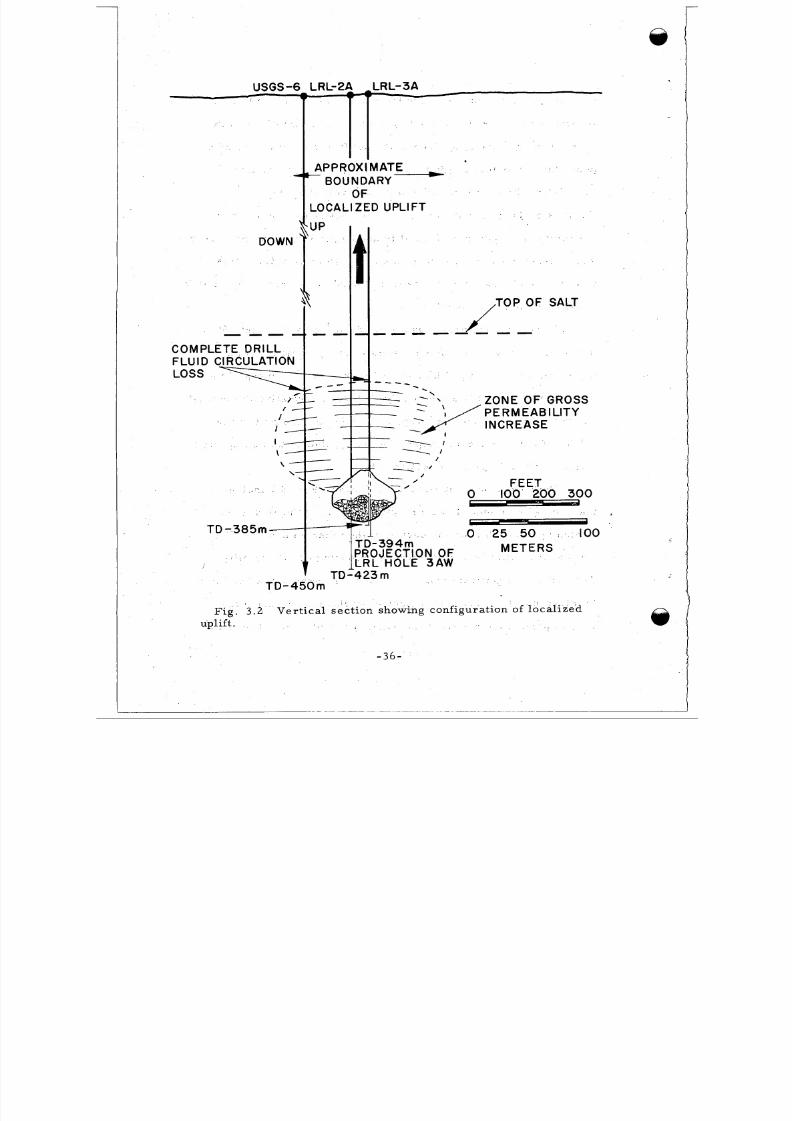
The cone-s haped uplifted zone shown in F i g . 3 . 2 indicates
that a pos sible effect of backdropping of s om e of the ro ck i s to
t igh ten up the a r ch ove r the cav i ty , ra th er than weaken i t .
pro ce ss ma y have been impor tan t in p roduc ing cav i ty s t ab i l i t y .
The lack of a signi f icant num ber of open fr ac tu re s above the cavi ty
to in t e rconnec t the pres hot s t ru c tu ra l weaknesses in the rock i s
This
v e r y i m p o rt a n t f r o m a rad iat ion -sa fety point of view. The rad ial
-35-
8/8/2019 pne 107 Gnome
http://slidepdf.com/reader/full/pne-107-gnome 38/92
LOCAL1ZED UPLlF T
- - -
ZONE O F GROSS
FEET' 0 ' 100 200 300I
M E T E R S
t 0 25 50 , 100
TD-450m
F i g . 3.2 Ve rt ic al sec t ion showing configurat ion of local i zed
uplift .
- 3 6 - '
8/8/2019 pne 107 Gnome
http://slidepdf.com/reader/full/pne-107-gnome 39/92
f r ac tu re s tha t we re produced by the explos ion we re f i led,with me .t ,
sea l ing in the g a s e s .
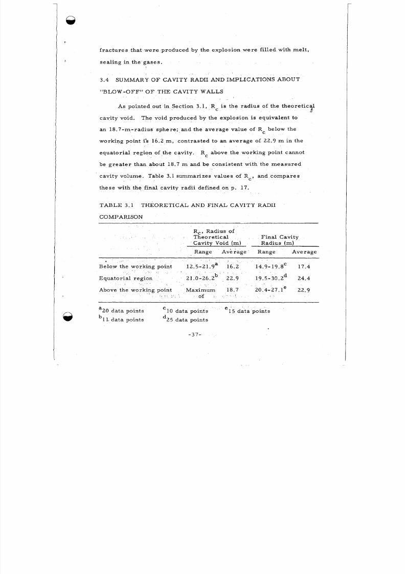
3.4 SUMMARY O F CAVITY RADII AND IMPLICA TIONS ABOUT
"BLOW -OFF" O F THE CAVITY WALLS
As pointed out in Sect ion 3.1, Rc i s the radius of the theoret icaldc
cavity void. The void produced by the explosion is equivalent to
an 1 8.7-m- radius sph ere ; and the ave rage value of Rc below the
working point i& 16.2 m , con tras ted to an avera ge of 22.9 m in the
eq ua tor ial region of the cav ity. above the working point cannot
be gr ea te r than about 18.7 m and be consis tent wi th the measured
cavi ty volume. Table 3.1 summarizes values of Rc, and co mp ar es
the se with the final cavity rad i i defined on p. 17.
RC
TAB LE 3.1 THEOR ETICAL AND FINAL CAVITY RADII
COMPARISON
R,, Radius ofTheore t i ca l F ina l Cavity
Cavity Void (m ) Radius ( m )
Range Avera ge Range Avera ge
Below the workin g point 12.5-21.9a 16.2 14.9- 19.8' 17. 4
Equ ator ia l region 21.0-26.zb 22.9 19.5- 30.2 24.4
Above the work ing point Ma xim um 18.7 20.4-27. l e 22.9
of
a C e
b l 1, da ta poin ts
20 data points 10 data points 15 data po in ts
d25 data points
-37-

8/8/2019 pne 107 Gnome
http://slidepdf.com/reader/full/pne-107-gnome 40/92
Much of the var iat ion in both R and f ina l cavi ty radi i shownC
by the range va lues in the table can be expla ined by observ ed dif fer-
ent ia l movement of rock a long fault planes disc ussed in Sect ion 4.3
on rock deformat ion.
In the region below the working point and in the equatorial
gegion , the difference between the ave rag e radi us of the cavity
void (Rc) and the f ina l cavi ty r ad i i i s about 1.2 m .
tha t this thickness r ep re se nt s an annular she l l of the cavi ty wal l
t h a t b r e a k s u p , d e c r e p i ta t e s , s p a l l s , o r i s imploded into the cavity.
Thus openings develop in the rock bounding the lower hemi sph ere
of the cavi ty and the f luid, radioac t ive salt me l t invades these open-
ings . The extent of the mel t def ines the f ina l cavi ty boundary. This
annular zone i s called the "blow-off" zone; i t pro du ces the ro ck that
It s e e m s p r obab l e
*
blows into the cav ity wh ere i t mi xes with and cools the mel t . As sum -
ing tha t the average thickness of this zone is 1.2 m sur rounding an
18.7-m-rad ius s phe r e , then about 5 .6 X 10 m of rock mixed wi th3
6about 3.2 X 10 kg of mel t in the rubble i s "blow-off" ma te r i a l f ro m
3 3the cavi ty wal l s . The dif ference be tween 5.6 X 10 m and the e s t i -
3mate d tota l rubble volume is 11.46 X 10
be the amount added by ceil ing collapse into the cavity.
i s a sche matic drawing i l lus t r a t in g the "blow-off" phenomena and
the va r iou s d imens ions d i scuss ed above . Appendix E i s a f u r t he r
m 3, which would rough ly,
F igu r e 6 . l b
d iscuss ion of the rubble dis t r ibut ion .
-38-
8/8/2019 pne 107 Gnome
http://slidepdf.com/reader/full/pne-107-gnome 41/92
CHAPTER 4
FRACTURING AND DIFFERENTIAL ROCK MOTIONS
4 .1 LOCAL UP LIF T O F STRATA OVER THE SHOT POINT
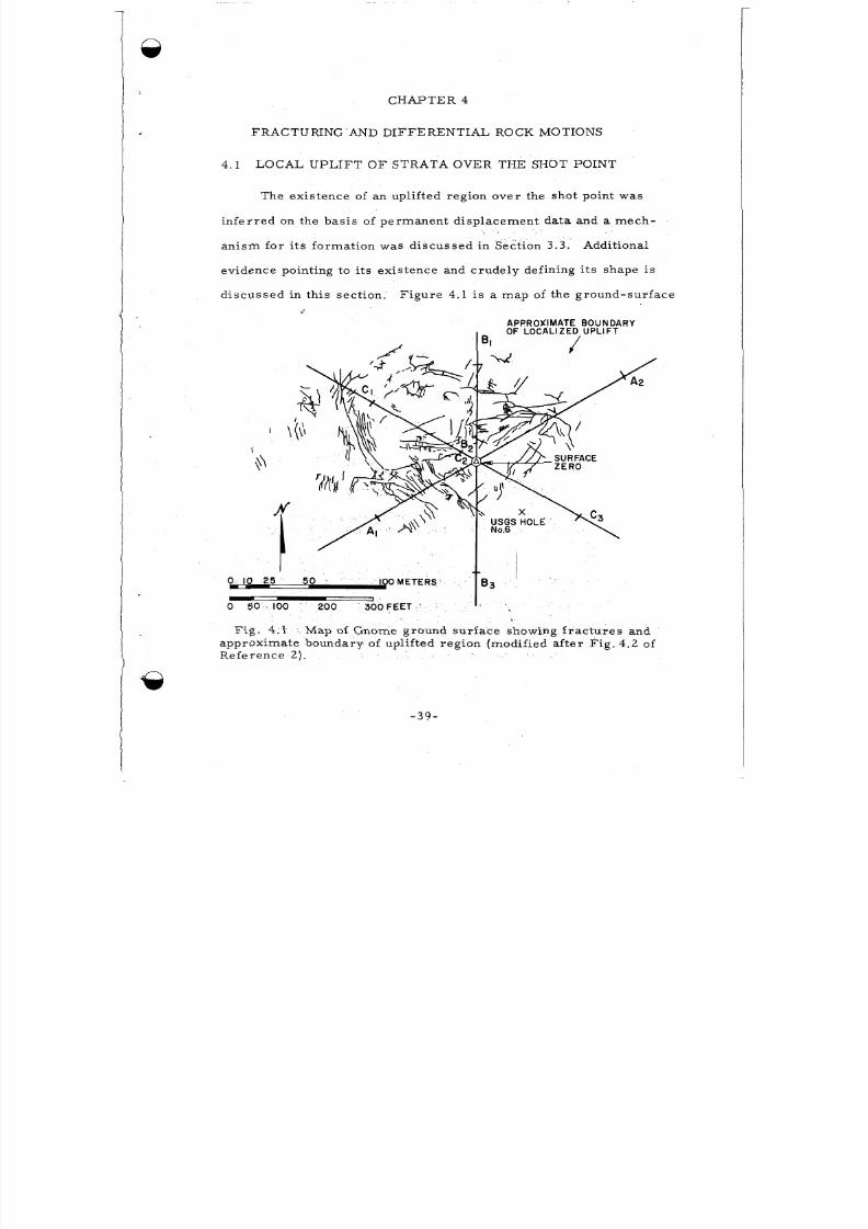
The exis t ence of an upl i f ted region ov er the shot point was
in fe r red on the bas i s of pe rman ent d i sp laceme nt da ta and a m e c h -
a n i s m f o r i t s f o r m a t ion w a s d i s c us s e d i n Se c ti on 3 . 3 . Additional
evidence point ing to i ts exis ten ce and cru del y def ining i ts shape i s
d i s c us s e d i n th i s s e c t ion . F igu r e 4 . 1 is a ma p of the grou nd-su rface
' \\
9
I F E T E R S
1
0 50 100 200 300 F E E T
APPROXIMATE BOUNDARYOF LOCALIZED UPLIFT
BI /
83
Fig . 4.1approxima te boundary of upl i f ted reg ion (modi f ied a f te r F ig . 4 .2 of
Refe rence 2 ) .
Map of Gnome ground su r fac e showing f ra c t ur es and
- 3 9 -
8/8/2019 pne 107 Gnome
http://slidepdf.com/reader/full/pne-107-gnome 42/92
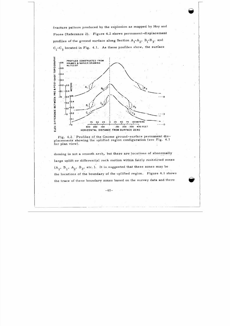
f ra c tu re pa t t e rn produced by the explos ion as mapped by Hoy and
Foose (R e fe rence 2) . Figure 4 .2 shows pe rm anen t -d i sp l acem en t
p ro f i l e s of the groun d su rf ac e along Section A1-A2, Bl-B3, and
C1-C loc ate d in Fig. 4.1. As these prof i l es show, the sur face3
I.I
a P R O F I L E S C O N S T R U C T E D F R O M '2 10.6 HOLMES 8 N A R V E R D R A W I N G
a No.F.D.137
-0
-0
--0
W HORIZONTA L DISTANCE FROM SURFA CE ZE RO
F i g . 4.2 ' Pro f i l es of the Gnome ground-sur face per man ent d i s -
plac em ents ' showing ?he upl if ted region configurat ion ( se e Fig. 4 .1
fo r p l an v i ew ) .
doming i s no t a smooth a r ch , bu t the re a r e loca t ions of abn ormal ly
la r ge up li ft o r d i f fe ren t i a l rock mot ion wi th in fa i r ly re s t r i c t e d zones
(A1, B1, A2, B2, e t c . ). It i s sugges ted t hat t he se zones m a y be
the locat io ns of the boundar y of the uplifted region.
the t r ac e of th ese boundary zones based on the s urv ey da ta and the re
F i gu re 4 .1 shows
-40 -
8/8/2019 pne 107 Gnome
http://slidepdf.com/reader/full/pne-107-gnome 43/92
.
is a pa r a l l e l i s m betw ee n t h is t r a c e a nd t he t r a c e of ob s e r ve d s u r f a c e
f r a c t u r e s .
The USGS dr i l l e d ve r t i c a l hole #6 a t a dis tance of 46 m f r o m
Thi s ho le e nc oun te r e d f r a c tu r e s at depth s ofur face ground ze ro .
122 and 183 m f r om the s u r f a c e ( R e f e r e nc e 9 ) . This f r a c tu r i n g m a y
be as so cia ted with the boun dary of the uplif ted region . This boundary
is probab ly broad and dif fuse consis t ing of s l ight ly folded s t ra ta and
s o m e s h e a r f r ac t u ri n g .
upl if t though loca l ized perm it t ed leakage of radioac t iv i ty f ro m the
immed ia te cavi ty envi ronment .
T h e r e i s no evidence indica t ing tha t
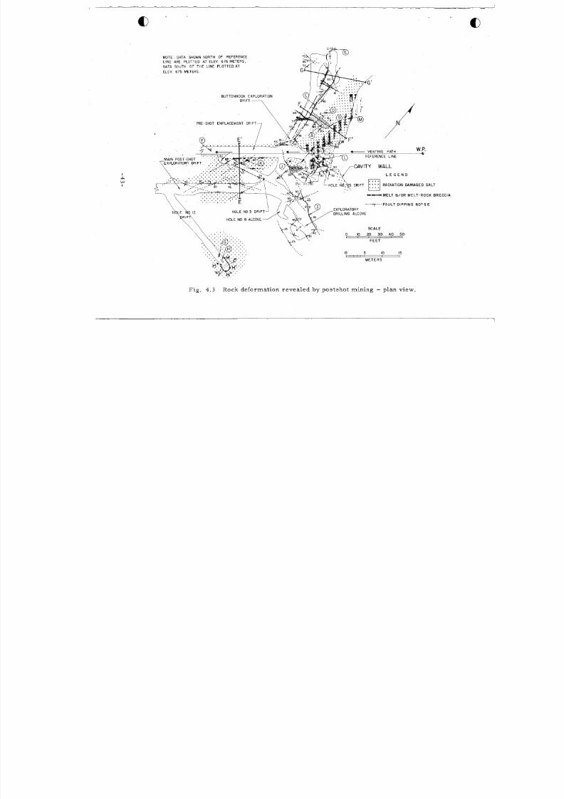
4.2 ME LT AND GAS INJE CT ED FROM THE CAVITY INTO
FRACTURES
Ir rad ia t io n of ro ck salt re s u l t s in d i s t inc tive yel low, b lue ,
a nd pu r p l e co lo r at i on . F o r t h i s r e a s on , a r e a s w he r e r a d ioa c ti ve
g a s e s w e r e able to p e r m e a t e a r e de tec tab le even though r ad ia t ion
l e ve l s i n s om e in s t a nc e s w e r e ne a r ba ckgr ound at the t ime of explo-
r a t i on . Molten sal t i n j ec t e d i n to ' c r a c k s f r o m the c a v it y c ha r a c t e r -
is t ica l ly is black and conta ins varying amounts of rad ioac t ivi ty.
U sing t he s e c o lo r c r i t e r i a , i t was o bse rve d thgt above the working
poin t , both gases and s l igh t ly rad ioac t ive me l t pe rme a ted a dis tance
of 3 8 m f ro m the wo+r,kingpoint . This is r a t h e r s u r p r i s i n g s i n c e a
zone of g rea t ly inc rea sed pe rm eabi l i ty ex tends ve r t i ca l ly to a d i s -
tance of about 105 m .
', I
Bec ause of the infrequ ency of m el t inje ctio ns
-41 -
8/8/2019 pne 107 Gnome
http://slidepdf.com/reader/full/pne-107-gnome 44/92
A.
B.
C.
D.
E .
F .
G.
H.
I.
J.
K.
L.
M.
LEGEND - F i g . 4 . 3
Ec h e lo n t en s io n f r a c t u r e s r e su l t i n g f r o m m o ve m e n t on m a j o r I1
t h rus t f au l t .
Voids encou ntered a t th is locat ion .
Majo r thru st faul t as so cia ted wi th c lo su re of the "buttonhookd r i f t . f
Pro bab ly extend fu ll length of "but tonhook d r i f t .
Abrup t t e rmina t ion of r ad ia t ion damage a t t ens ion f r a c tu re .
Appro ximate p ost sho t boundary of lef t r ib of "buttonhook"
indicate d by extent of m e l t a nd r o c k b r e c c i a .
Approx imate ex ten t of ma jo r tunne l c lo su re .
Encoun te red wa t e r l eakage f ro m po lyha li te # 9 4 f r o m t h i s p o in t
to end of dri ft .
Locat ion of a c c e l e r o m e t e r th a t fa i l ed at 16 m s e c .
M a j o r o v e r t h r u s t f a u l t w ith m a x i m u m o b s e r v e d d i sp l a c e m e n t
of 3 m ( s e e F i g . 4 . 6 a ).
Pos tsho t locat ion of sand bags in hole #25 a lcove.
Sheet of radioac t ive me l t in jec te d a long a par t ing o f c l ay beds .
Pr es ho t locat ion of hole #25 a lcove .
Pr es h ot locat ion of "buttonhook drif t . '
-42-
8/8/2019 pne 107 Gnome
http://slidepdf.com/reader/full/pne-107-gnome 45/92
I
,
NOT E. DATA SHOWN NORTH OF REFERENCELINE ARE PLOTTED AT €LEV 676 METERS,
DATA SOUTH OF THE L INE PLOTTED AT
ELEV. 675 METERS.
BUTTONHOOK E
CAVITY WALL
L E G E N D
- M E L T & / OR M E L T - R OC K B R E C C I A
t + + l t * *
- - - - - - - F A U L T D I P P I N G 60"s
EXPLORATORY
DRILLING ALCOVEOLE NO 3 DRlF
HOLE NO. 8 ALCOVE
S C A L E
F E E T
0 5 IO 15
M E T E R S
F i g . 4 . 3 Rock deformat ion reveal ed by postshot mining - plan view.
8/8/2019 pne 107 Gnome
http://slidepdf.com/reader/full/pne-107-gnome 46/92
and radiation-damaged sal t encou ntered in explo ra t ion of this r egion ,
the re la t iv e ly sh or t ve r t i ca l ex ten t of these in jec t ions above the work-
ing point , and s ince the amou nt of ra dioac t ivi ty in the injec ted mel t
is muc h lower than me l t encoun te red with in the cavi ty ; i t i s concluded
tha t the open f ra c tu res communica t ing wi th the cavi ty deve loped
ea r l y dur ing the dynamic growth pe r iod .
100 m s e c ) i s l ike ly because good phy sica l mixing be tween the molten
roc k and the vapor ized f i s s ion prod uc ts would not ye t have occ ur re d .
Injec t ion at th i s t ime (10-
In the equato r ia l regi on beyond the cavi ty , m e l t wa s obs e r ve d
a s f a r a s 40 m f r om the working point , and evidence of gaseo us
injec t ion w a s obs e r ve d as far out a s 65 .5 m . The s e d i s t a nc e s r e f e r
to me l t and gas in jec t ions tha t a r e be l ieved to be u nre la ted to the
vent pa th down the l ine -of -s ight e mp lace me nt d r i f t .
into a c lay pa r t ing a long the l ine -of - s igh t emplacem ent d r i f t to a
dis tance of 58 m f ro m the working poin t , and me l t was a l so in the
d r i f t as f a r away as the conc re te b lock s temming (F ig . 1 .2) .
f r o m t h is d r i f t w e r e a l s o p e r m e a b l e to g a s e s .
Melt was injec ted
C r a c k s
F i g u r e 4 . 3 shows
the f rac tu r ing and the d i s t r ibu t ion of r ad ia t ion-dam aged sa l t and
me l t in jec t ion in th i s equ a tor ia l r eg ion .
P r e s ho t hol e #12 w a s e xp lo r e d t o r e c ov e r a n i n s t r um e n t t ha t
f a i le d a t 16 m s e c ( R e f e r e nc e 6 ) following the explosion.
to have been loca ted in a reg ion of anomalous ly la r ge rock de form a t ion
with accompanying rad ia t ion da mag e in the sa lt . and wa ter leak age
( F i g . 4.3) indica t ing pe rm eab le commu nica t ion with the cavi ty. The
It was found
-44-
8/8/2019 pne 107 Gnome
http://slidepdf.com/reader/full/pne-107-gnome 47/92
e a r y fa i lu re of the ins t ru men t , coupled wi th the in t ense loca l de for -
mat ion and i t s assoc ia t ed permeabi l i ty communicat ing with the cav i ty ,
ind ica tes tha t the f rac tur ing s t a r t e d a t about 1 6 m s e c , o r i m m e d i-
ately fol lowing the pass ag e of the com pr es sio na l shock wave. The
c r os s s ec t ion H -H '" ( F i g . 4.4) located in plan in F i g . 4.3 i s a
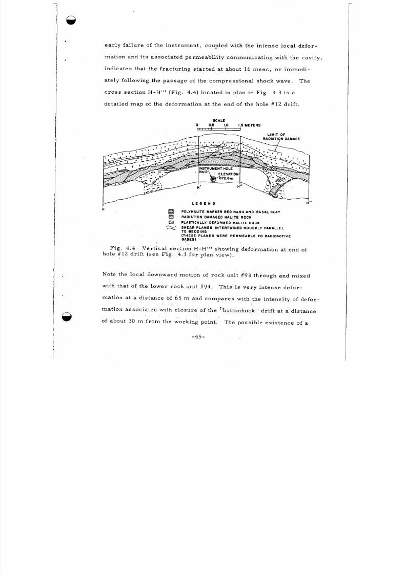
deta i led ma p of the def orm atio n at the end of the hole #12 dri ft .
SCALE-0.5 1.0 1.5 M E T E R S
L I M I T O F
L E G E N D
POLYHALITE MARKER BED No.94 AND BASAL CLAY
RADIATION DAMAGED HA LITE ROCK
PLASTICALLY DEFORMED HAL ITE ROCK
S H E AR P L A N E S I N T E R T W I N E D R OU G H L Y P A R A LL E LTO BEDDING.( T H E S E P L A N E S W ER E P E R M E A B L E T O R A D I O AC T I VEG q S E S )
H
Fig . 4 .4 Ver t i ca l sec t ion H-H"' showing defor mat ion at en d ofhole #1 2 d r i f t ( s e e F i g . 4 . 3 fo r p l an v i ew ) .
Note the lo ca l downward motion of ro ck unit #93 throug h and mix ed
with that of the lowe r ro ck unit #94.
mat ion at a distance of 65 m and compares wi th the intensi ty of defor-
mat ion assoc ia t ed wi th c los ure of the "buttonhook" d ri ft at a di s t ance
of about 30 m f ro m the working point .
T h i s i s ve r y in t ense de fo r -
The possible exis tenc e of a
-45-
8/8/2019 pne 107 Gnome
http://slidepdf.com/reader/full/pne-107-gnome 48/92
na tu ra l cavi ty in the s a l t nea r the ins t ru men t loca tion tha t was co l -
lap sed by the shock wave could be the explanation of th is defo rmat ion.
Such cavi t i e s a re known to occur in the Sa lado forma t ion (C . Jon es ,
ve rb a l communica t ion) and a r e gene ra l ly br ine - f i ll ed .
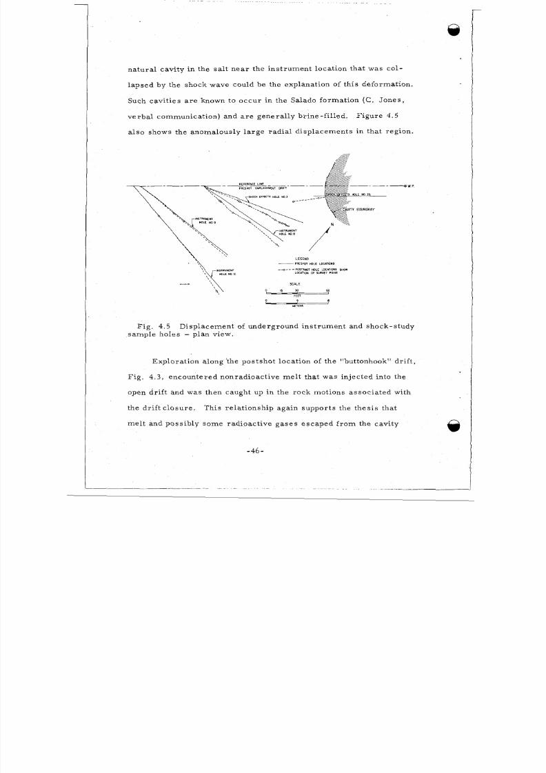
a l so shows the anomalous ly la rg e rad ia l d i sp lacements in tha t r eg ion .
F igu r e 4.5
.-----wp
S HOLE NO 25
LEGEND-RESHOT HOLE LOCbTlONS
--o-- - PoS TSm T HOLE LOCbTlONS SHOW
LOCbTlON OF SURVEY POINT
SCALE
0 15 50 60
- b - I
L Y I P Sl
FEET
0 9I-METERS
F i g . 4 . 5 Disp lacement of underground ins t ru men t and shock-s tudy
sample hole s - plan view.
Exp lora tion along ' the pos tsho t loca tion of the "buttonhook" dr if t ,
F i g . 4 . 3 , encoun tered nonradioact ive me l t tha t was injec ted into the
open dr i f t and was then caught up in the ro ck motions asso cia ted with
the dr i f t c losu re . This re la t ionship aga in suppo r t s the thes i s tha t
me l t and poss ib ly som e rad ioac t ive gases e scap ed f r om the cavi ty
- 4 6 -
8/8/2019 pne 107 Gnome
http://slidepdf.com/reader/full/pne-107-gnome 49/92
. . - . .. . . - - . . . . . . .. . - -
pr i ma r i l y dur ing dynamic cavi ty growth . An exception , of co urs e ,
is melt and gases tha t vented into the e m pla c e m e n t d r i f t .
Be low the shot po in t , ne i th e r me l t s am ple s , r ad ia t ion-damaged
sa l t , nor rad iat ion leve l s above background, we re noted fur th e r than
25 m f r om the working poin t o r 6 m beyond the cavity edge.
4.3 DEFO RMAT ION SURROUNDING THE CAVITY
Fr ac tu re s re su l t ing f r om the expanding cavi ty produced by the
explosion and subsequent f rac tu re development asso cia ted with unload-
ing of the co mp res sed rock can be grouped in to the fol lowing four
ge ne r a l c a t e go r i e s :
(1) Radia l t ens ion c rac ks emana t ing f ro m the cavi ty ;
( 2 ) Pe r ip he r a l f au l t s with p lanes tha t gene ra l ly pa ra l le l the
c av i y bound a r y ;
(3 ) Bedding plane faul ts ;
( 4 ) N e a r v e r t i c a l j o i n ts p r i m a r i l y i n th e v i c i n it y of p r e s h o t
e m pla c e m e n t d r i f t s .
F i g u r e 4 . 3 shows the pro jec t ion of the t r a ce s of ma jo r fau l t s ,
and joints a t the ele vati ons of 674.8 and 675.7 m tha t were revea led
dur ing mining explora t ion .
of the inte r io r of the cavi ty showing the t r ac es of maj or radi a l c r ac ks .
F igure 2 .1 i s a ref lec ted ce i l ing plan
These c racks ( type 1 ) occu r wi th a f requen cy of about one ev er y 4
o r 5 m at the eq uato r of the ca vity and extend to a d i s ta nc e l a t e r a l l y
and above the cavi ty of about 38 m . The se ar e the cr ac ks conta ining
-47-
8/8/2019 pne 107 Gnome
http://slidepdf.com/reader/full/pne-107-gnome 50/92
in jec ted me l t ( see F ig . 4 . 3 in the reg ion of the "buttonhook dr if t ' '
and the ve r t i ca l sec t ion F i g . 2.2).
Also shown in these two f igures a r e the curved pe r iph e ra l
fau l t s .
faults ( type 2) a r e i n f e r r e d f r om the a t t it ude of fault planes in the
Below the shot point in dr i l l holes B and C , the pe r iphe ra l
cor e re la t iv e to the or ienta t ion of bedding plan es .
the dr i l l a lcove (Fig . 4 .3) , this type of fault ing grad es into ov er th rus t
faul ts tha t fur the r grade into hor izonta l bedding-plane s l ips a long
clay seams.
In the vicinity of
0
F i g u r e s 4.6a and b shows examples of this kind of fault-
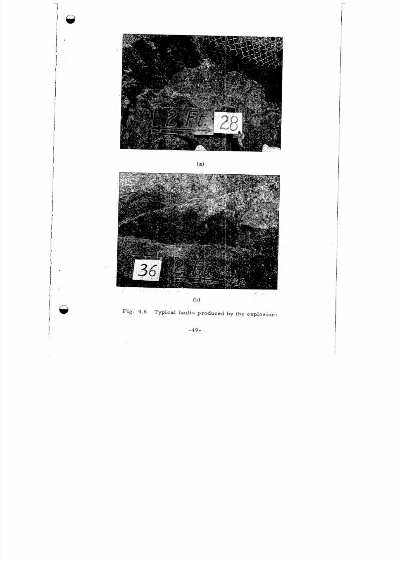
ing. . The throw o r dif ferent ia l motion be tween blocks was m ea su re d
to be 2.5 to 3.0 m a c r o s s t he f a ul t m a r k e d ( I) n Fig . 4 .3. This was
the la rge s t f au lt obse rved; m os t d i f fe ren t ia l mot ions a r e on the ord e r
of 0.5 m o r less . . This per iph era l type of faul ting does not conta in
me lt injec t ions and i s probably formed af te r cavi ty growth when
unloading o r r ebound adjus tments to the s t re s se d rock a re l ike ly to
take place .
region below the cavity i s a gentle upwarping of the s tr at a in the
Associa ted with these curv ed faul ts emanat ing f ro m the
equ ator i a l region. Ma rke r bed #94 which was loca ted a f ew m e te r s
below shot point became upl i fted f ro m i t s pres ho t e levat ion out to a
dis tan ce of about 64 m . Beyond tha t point , the ver t ica l displacement
i s not meas urab le . In the dr i l l a lcove polyhal i te m ark e r bed #94 was
upl i fted f ro m 0.3 to 0 .6 m ins tead of be ing depre sse d. This bed was
loca ted below the working point e levat ion pr io r to the explosion (see hFig . 2 .1) .
-48-
8/8/2019 pne 107 Gnome
http://slidepdf.com/reader/full/pne-107-gnome 51/92
(b)
F i g . 4.6 Typical fau l t s produced by the explosion:
-49-
8/8/2019 pne 107 Gnome
http://slidepdf.com/reader/full/pne-107-gnome 52/92
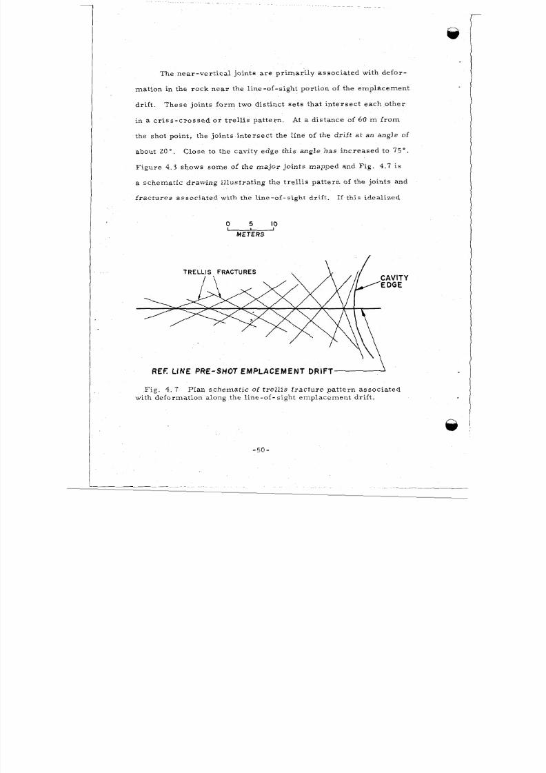
T h e n ea r - v e r t i c a l j o in t s a r e p r im ar i l y a s s o c i a t ed w ith d e f o r -
mat ion in the ro ck nea r the l ine-o f - s igh t por t ion of the emplacem ent
dr i f t . These jo in t s fo rm two d i s t inc t s e t s that i n t e r s e c t e a c h o t h e r
in a c r i s s - c r o s s e d o r t r e l l i s p a tt e rn . At a dis tan ce of 6 0 m f r o m
the shot point , the jo ints in te rs ec t the l ine of the dr i f t a t an angle of
about 20". Close to the cav i ty edge th i s ang le ha s in cr ea sed to 7 5 " .
F ig u r e 4 . 3 shows some of the ma jo r jo ints mapped and F ig . 4.7 i s
a schem at ic d rawing i l lus t r a t in g the t r e l l i s p a t te rn of the jo in ts and
f r a c t u r e s a s s o c ia t e d w i t h the l i n e - o f - s i g h t d r i f t . If th i s idea l ized
5 IOO U
METERS
\>REF. LINE PRE-SHOT EMPLACEMENT DRIFT
F i g . 4. 7 P lan s ch em a t i c of t r e l l i s f r a c tu r e p a t t e r n a s s o c i a t ed
with deform ation along the l ine -of - s igh t em p lacem en t d r i f t .
- 50 -
8/8/2019 pne 107 Gnome
http://slidepdf.com/reader/full/pne-107-gnome 53/92
i n t e rpre t a t ion is co r re c t , i t ind i cat e s t hat
fa i l ed in sh ea r as the com press ion a l wave
cavi ty growth d i s to r t ed thes e weak zones .
the r oc k bounding the dri ft
passed and subsequent
4.4 DEFORMATION O F THE PRESHOT EM PLACEM ENT DR IFT
In addi tion to the t re l l i s p a t t e r n of f ra c t ur es as soc ia t ed wi th
the d efor mat ion of the l ine -of- s ight port ion of the e mp lace men t dri f t ,
t he dr i f t was no t i ceably co ns t r i c t ed by p las t i c d eformat ion . C r o s s
sec t ion E - E ' (F i g . 4.8) located in plan on F i g . 4.3 shows the approx -
im ate s i ze of the pos t sho t emplacemen t d r i f t at 53.3 m f r o m t he
working point compared to its p r e s h o t c r o s s s e ct io n .
the dr i f t apparen t ly squeezed nea r ly shu t p r io r to vent ing and was
At this dis tance,
RADIOACTIVE MELT
PR E- S HOT CROSS-S ECT I0OF EMPLACEMENT DRIFT
ELEV. METER S
'TRELLIS"FAU LTS
POST- SHOT E X PLO RAT0RY DR IFT DRIFT PRE-SHOT ELEVATION/OF MARKER BEDSMETERS
0 1 2 3.-
SCALE
ROCK U N I T N 0 . 9 0 - C L A Y
R O C K U N I T N 0 . 9 4 - P O L Y H A L I T E
Fi g . 4.8 Vert i ca l sec t ion E - E ' showing par t i a l c los ure of p r e s h o t
em pl acem en t d r i f t ( s ee Fig . 4.3 for p l an v iew) .
-51-
8/8/2019 pne 107 Gnome
http://slidepdf.com/reader/full/pne-107-gnome 54/92
then blown open to i t s f ina l shape when vent ing o ccu rre d ( see dis -
cussion on Venting - Chapte r 5).
The curved o r "buttonhook" por t ion of the emplacem ent dr i f t
sea l ed effec t ive ly and was not involved in the cav i ty vent ing p ro ce ss .
The explo red por t ion of this dr i f t was tangent ia l to the shot point
ra the r than rad ia l (a s was the empla
cus s io n) , and the na t ure of tunnel c losur e was qui te dif ferent .
l ine -of -s ight d r i f t , ineffec t ive c lo sur e was accomplished by plas t ic
I
ment d r i f t in the previous d i s -
In the
flow and slippage along the t r e l l i s f r ac tu re s . In the "buttonhook"
por t io n of the dr i f t , the ra di a l component of the outw ard moving,
c om pr e s s iona l s hock w a ve m e t t he d r i f t at a r ight angle and vir tua l ly
s lam med one wa l l in to the o th e r . More pre c i se ly , the c losure was
accomplished by the movement of a wedge-shaped block into the open
dr i f t .
c lay s ea m s in the rock tha t appea .r to have lub r ica ted the movement
of the m aj or block. Fig ure 4.9 shows two c ross sec t ions i l lus t ra t -
ing the de ta i led s t r uc tu re of the deformat ion; th e ir loca t ions in plan
The boun'dar ies of this m aj or block a r e pa r t l y control led by
v ie w a r e m a r ke d i n F ig . 4.3.
In the vic init y of Sec n G-GI , radia l c racks fol lowing the
com pre ss io nal shock wave opened up, a l lowing superhea ted mel t to
e n t e r t he d r i f t p r i o r t o i t s c l o s u r e . H e r e , t he m e l t w a s mixed and
trap ped with the r ock moving to s ea l off the d r i f t and i t fo rm ed the
matr ix of a m e l t - r o c k b r e c c i a .
the me l t encounte red lead b r icks and wood in an ins t rumen t a lcove
A s it was injec ted into the dr i f t ,
@.
- 5 2 -
8/8/2019 pne 107 Gnome
http://slidepdf.com/reader/full/pne-107-gnome 55/92
..
E>
a
W
In
wb p
JW
Y
I
I
I
I
1 m
pW
p
p
(
W
W 8
w
(3
)[LW I-W z
'El Y
2
,
I
I
I
I
b
W
n,*m
(c
p
p
p
W
W
W
W
'P
pW
w-53-
8/8/2019 pne 107 Gnome
http://slidepdf.com/reader/full/pne-107-gnome 56/92
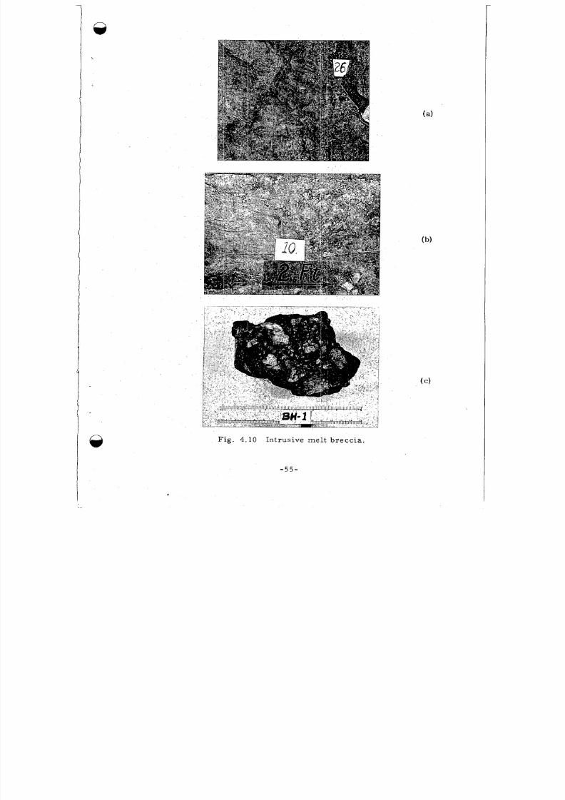
off the drift . The lead mel ted and the wood burned mixing wi th L e
sa l t - m e l t b r e c c i a . Analyses of the me l t bre cc ia shown in F ig . 4 .10a,
b , and c , i nd ica te tha t l ead combined wi th su l fu r and ch lo r ine f r om
the m el t to fo rm galen a (PbS) and laur ioni te (Pb[OH12-Pb[C112)
(Refe rence 10) .
of wa te r d i sso lved in the sa l t me l t w ith PbCl 2'
The l au r ion i t e was p robab ly fo rmed by the r eac t ion
Th e su lf u r n e c e s s a r y
to combine with the lead was probab ly re lea se d by a reduct ion of
su l f a t es a sso c ia t ed with the m ol t en sa l t .
burning wood c r e a t e d a r educ ing a tmosphere .
nat ion of the for mat ion of the me l t bre cc ia i s that it w a s produced
l o c a ll y in th e d r i f t by e x t r e m e l y h ig h p r e s su r e s a n d t e m p e r a t u r e s
H y d r o c ar b o n s f r o m t h e
An a l t e rna t ive expla-
developed f ro m the dynamic condi t ions of c los ure . The hypothesis
of m el t in jec t ion f r om the cavi ty (ev en though it i s nonrad ioac t ive )
i s m os t cons i s t en t wi th the r e l a t ionsh ips obs e rved . Some of the se
re l a t ionsh ips a r e as fol lows:
1 . Voids in the sa me r eg ion a r e coa ted with a mixture of
soo t , l ead , and fused sa l t ( s ee Sec tion G - G ' of Fig. 4.9);
2. In the b re cc ia , i n su la t ion was s t i l l on wi re s and shock-
.*.bands-'. we re no t found in r eco vere d s t e e l s amp les
t ima te ly mixed wi th the m el t , i nd ica t ing not ne a r ly
h igh enough p r es su re s deve loped fo r me l t ing ;
.8.
N e um a nn b a nd s a r e c h a r a c t e r i s t i c d e f o rm a t i o n f e a t u r e s i n s t e e l
caused by in t ense shock o r impac t load ing ,
-54-
8/8/2019 pne 107 Gnome
http://slidepdf.com/reader/full/pne-107-gnome 57/92
Fig. 4.10 In t ru s i ve m e l t b rec c i a .@
-55-
I
8/8/2019 pne 107 Gnome
http://slidepdf.com/reader/full/pne-107-gnome 58/92
3 . The percentage of mel t , lead, and carbon in the bre cc i a
dec reas es f ro m tha t loca ted in the v ic in ity of c r os s sec tion G-G'
unt i l absent f ro m the bre cc ia in the vic ini ty of c r os s s e c ti on F - F ' .
Most of the m at r i x of the bre cc ia is c lay at tha t loca t ion.
4. As shown in Fig . 4.2, the pre sh ot siz e of the dri f t was
large where the a lcove i s loca ted comp ared to the r es t of the dr i f t .
This por t ion of the d r i f t i s a ls o ne ar es t the shot point and thus a
logica l place for c ra cks to open to mel t injec t ion f ro m the growing
cavi ty.
i t would have ' had to fol low im med ia te ly behind th e com press ion al
shock wave to ge t to the dr i f t pr io r to c los ure .
occ ur r ed ve r y ea r ly in the dynamic cavity growth pe r iod; whi le the
cavi ty was smal l and the thick ness of rock mel ted by the shock waves
w a s r e l a t i ve ly l a r ge ( s e e F i g . 6 . l a ) .
mixing of the thick mel t zone with the vap oriz ed fissi on produ cts
would be l ikely and then explain the nonradioactive melt found in
the dr i f t .
If the m e l t w a s injected f r o m the cavi ty into the cra ck s
This would have
Under these conditions poor
- 5 6 - ,
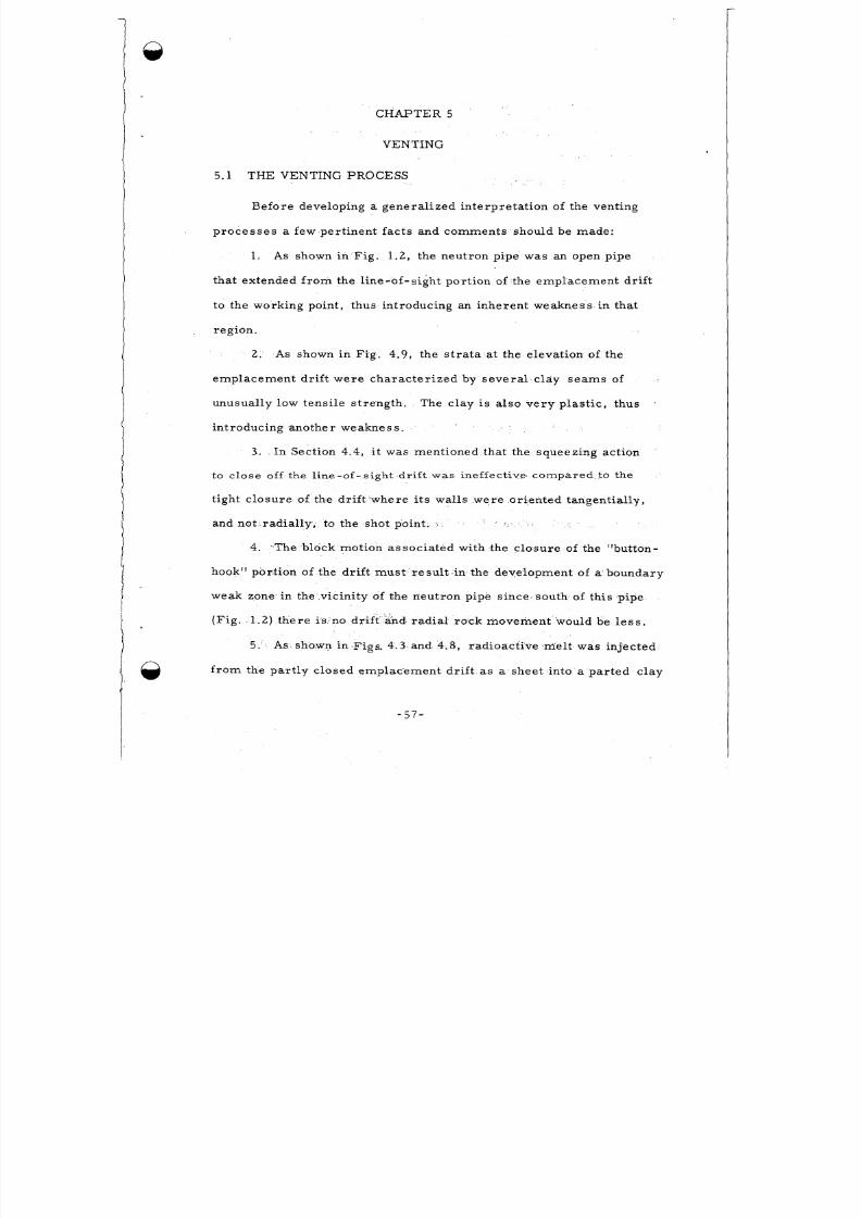
8/8/2019 pne 107 Gnome
http://slidepdf.com/reader/full/pne-107-gnome 59/92
CHAPTER 5
VENTING
5.1 THE VENTING PROCESS
Before developing a gene ral ize d in terpre ta t ion of the vent ing
p r o c e s s e s a few per t inent f ac t s and comm ents should be made:
1. As shown in F ig . 1 .2, the neut ron p ipe was an open p ipe
that extended f r o m the l ine-of -s ight por t ion of the empl acem ent dr i f t
to the w orking point, thus in t roducing an i nheren t weakness in that
region.
2. As shown in F ig . 4.9, he s t r a ta a t the e levat ion of the
e m p l a c e m e n t d r if t w e r e c h a r a c t e r i z e d b y s e v e r a l c l dy s e a m s of
unusual ly low tensi le s t reng th . The c lay i s a l so v e r y p l a s t i c , t hu s
in t roducing another weakn ess .
3 . In Section 4.4, t was ment ioned that the squeezing act ion
to c l o s e o ff the line-of-sight d r i f t was inef fec t ive ' c o m p a r e d to the
t i gh t c los u re o f the d r i f t where i t s wal l s were o r i en ted t angen ti a l ly ,
and not ra dia l ly , to the s hot point. I
4. %The lock motion as so ci at ed with the c lo su re of the "button-
hook" por t ion of the dr i f t m us t r es ul t in the development of a boundary
weak zone in the vicin i ty of the neutro n pipe sinc elso uth of thi s pipe
( F i g . 1.2) t h e r e i s no dr i f t and rad ia l rock mo vemen t .would be le s s .
5. As sho.wn in Figs. 4.3 and 4.8, r ad ioac t ive m el t was in j ec ted
f r o m t h e p a r t l y c l o se d e m p l a c e m e n t d r i f t a s a shee t in to a p a r t e d c l a y
- 57-
8/8/2019 pne 107 Gnome
http://slidepdf.com/reader/full/pne-107-gnome 60/92
_./ . .
s e a m . He re the m el t quenched and was not vesic ula ted indicating
tha t i t so l id if i ed under h igh p re ss u r e and , the re fo re , before the
p r e s su r e d r o p th a t r e su l t e d f r o m v e nt in g .
6 . Vent ing oc cu r re d wi th in 1 minute af t er the explosion (Sect ion
1 .4 ) .
Between about 100 m s e c and one minute fol low.ing the ex plosion,
mel t and gas es wer e ab le to pene t r a t e f r om the cav i ty in to the c losed
but apparen t ly perm eabl e l ine -of - s ight por t ion of the empl acem ent
drift.
above.
This zone was es peci a l ly weak for re aso ns 1 through 4, i s t e d
The com pres sion al wave produced by the explosion was ref lec ted
at the ground sur fac e and re tur ned to the cavi ty region as a r a r e f a c -
t ion wave at about 320 m se c. The in tensi ty of th is wave m ay have
been g r e a t enough to put the roc k into tension and ca use par t ing of
the c l ay se am ( 5 above) . The permea bi l i ty i n th is region would then
b e m o m e n t a r i l y i n c r e a se d so t ha t me l t cou ld be in j ec ted f rom the
cav i ty in to the pa r t ing and p robab ly then in to the m or e pe rme ab le o r
open dr if t beyond.
r es i s t anc e to the cav i ty p r es su re and dynamic ven t ing occur r e d .
When th i s occ ur r e d the re was no longer much
Mel t , rock , neut ron p ipe , vent l ine , and mo st of what was in the
drif t were blown down the dr if t ,
domino ( F i g . 1.2).
Much deb r is p i led up a t the cem ent
Radioact ive m el t was encountered as far as the
concre te b lock s t emming ( F i g . 1.2). This s te mm ing ef fect ively
throt t led the dynamic venting and conver ted i t to a l eak . The dr i f t
- 58-
8/8/2019 pne 107 Gnome
http://slidepdf.com/reader/full/pne-107-gnome 61/92
f r o m the s temming in to the cavi ty was probably ne a r the ove rburden
pr es su re of 1 ,200 ps i .
pr e s su re bui l t up about 55 p s i - sufficient to b re ak one of two r up tu re
disks in the b la s t door .
shaf t , through a f i l t er and out nto the open.
s t e m m ing pe r f o r m e d a s i t wa s de s igned , t o ho ld ove r bu rde n p r e s s u r e ,
but i t was not gas - t igh t , Pa r t i cu l a te rad ioac t iv i ty and v iolent venting
we re contained unde rground whi le s te am and gaseous f i s s ion produc ts
Fr om the porous p lug to the b la s t doo r , the
F r o m the re , the blow-out cont inued up the
The con cre te block
e s c a pe d .
As was poin ted out by E . Te l le r (Refe renc e l l ) , the knowledge
of how to control vent ing could be ve ry impo rtan t in recov er in g
gaseous red ioe lements f rom a spec ia l ly designed nuc lea r device .
acc id ent , Gnome vent ing contr ibuted gre a t ly to this knowledge .
By
5 .2 THE VENT PAT H ENVIRONMENT
F o l l o w i n g i s a p i c t o r i a l t r i p d ow n t h e v e n t p a t h f r o m th e s h a f t
s ta t ion down the em plac eme nt dr i f t and into the cavi ty:
Re-entry down the shaf t 6 days fol lowing the explos ion rev ealed
H a i rl i ne c r a c k s w e r e obs e r ve d i n s e v e r a l p l a c e se r y l i t t l e da m a ge .
in the con cre te l ining of the s haft between the su rf ac e and the top of
salt .
planes be tween dif fer ing rock s t ra ta .
were seeping wa te r .
the sa l t , the r e i s an ind ica t ion of s l ight pa r t ing a t sev e ra l p lac es .
In gen era l , thes e c rac ks co r re la t e with the loca t ion of bedding
Severa l be low a de pt h of 146 m
Oth ers developed at joints in the cement . In
-59-
8/8/2019 pne 107 Gnome
http://slidepdf.com/reader/full/pne-107-gnome 62/92
These w ere inva r iab ly a s soc ia ted with the bedding p lane boundar ie s
of c lay se am s and s t r in ge rs of polyhali te and anhydr i te - planes of
essent ia l ly no tens i le s t r eng th .
f r om the sha ft wa l l s.
of ma te r ia l spa l led f ro m a ve r y f r i a b le s i l t s tone .
lowered to within a few m e t e r s of the bot tom s ta t ion o r dr i f t l eve l
where the d i sp lacement of a met al safe ty ra i l ing s topped i t .
shows the descent f ro m the cage to the dr i f t leve l and damage at the
bot tom s t a t i o n .
a c lay lay e r loca ted 1 m above .
region and m o s t l ike ly would not have o cc ur red i f t ha t cl a y s e a m
had been immedia te ly above the dr i f t ,
bottom of the shaf t was full of wa te r and the dr if t f loo r had up to 25
c m of s tanding wa te r . Mos t of the wa te r condensed f ro m vented
s t e a m ; how e ve r , s om e a l s o s e epe d f r om the a bove -m e nt ioned c r a c ks .
The sal t exposed in these underground workings was colo red due to
the high rad ia t ion f ie lds developed a s a re su lt of venting.
In gene ra l , ve r y l i t t l e rock spa lled
3At a depth of 326.1 to 327.4 m , about 2.5 m
The cage was
F ig . 5.1
No t ethe sag
ofthe ceil ing
w h e r e spa11o c c u r r e d t o
Spa11 i s t he m a jo r da m a ge i n th i s
A 4.6-m-deep sum p a t the
Figu re 5 . lb shows the "I" bea m wal l 'but t ress ing the con cre te
b lock s temming through which leakage occu r red . I t was de te rmined
tha t l eakage was re s t r i c t ed to th i s r eg ion by press ur iz i ng the Gnome
cavity with a ir and surveying the vent pa th leakage .
F ig ure s 5 . l c and d show a com paris on of the pre sho t and pos t-
shot condition of a por tion of the dri f t between the con cre te block
s temming and the b la s t do or , a distance about 270 m f r o m the s hot
-60 -
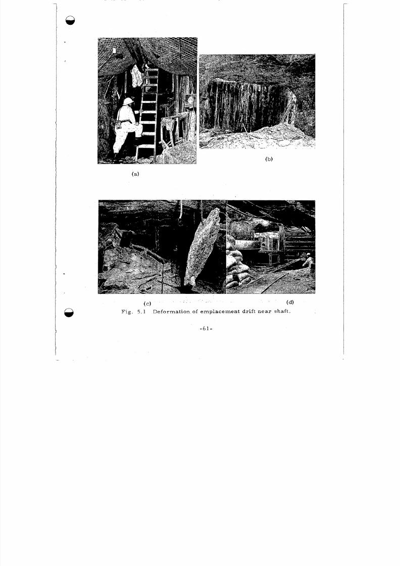
8/8/2019 pne 107 Gnome
http://slidepdf.com/reader/full/pne-107-gnome 63/92
F i g .
( c ) (4
5.1 Deformation of e mplace ment d r i f t ne ar shaf t .
-61-
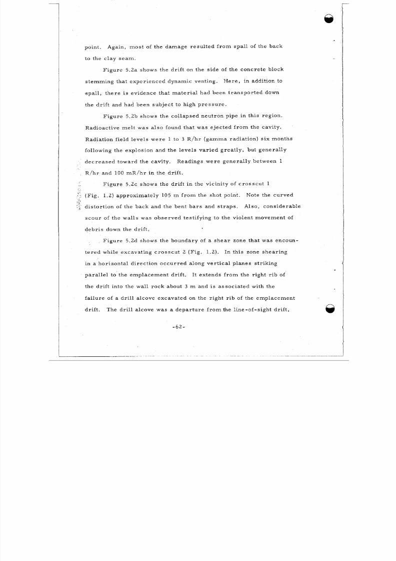
8/8/2019 pne 107 Gnome
http://slidepdf.com/reader/full/pne-107-gnome 64/92
point .
to the c l ay se am .
Again, most of the damage re su l te d fr om s pal l of the back
Figu re 5 .2a shows the dr i f t on the s ide of the co ncre te block
Here, in addi t ion totem ming that experienc ed dynamic venting.
spa l l , t he re i s ev idence t ha t m a t e r i a l had been t r anspo r t ed down
the dr i f t and had been sub jec t t o h igh pr es su re .
Fig ure 5 .2b shows the col laps ed neut ron pipe in this region.
Radioact ive m el t was also found that was eje cted fr o m the cavi ty .
Radiation f ie ld levels we re 1 to 3 R/hr (gam ma rad ia t ion) s ix months
following the explosion and the levels v ari ed gr eat ly , but gen era l ly
dec r ease d tow ard the cav it y .
R/h r and 100 m R /h r in the dri f t .
Readings were gen era l ly between 1
F i g u re 5 . 2 ~hows the dr i f t in the vicini ty of c ro ss cu t 1
( F i g . 1 .2) approximate ly 105 m f r om the sho t po in t .
dis to r t ion of the back and the bent bar s and s t ra ps .
sco ur of the wal ls was o bse rved test i fying to the violent movem ent of
debris down the dri f t .
Note the curved
Also, considerable
Fig ur e 5 .2d shows the boundary of a sh ea r zone that was encoun-
t e r ed whil e excava ting c r os scu t 2 (F ig . 1 .2 ) .
in a hor izonta l d i rec tion oc cu rre d a long ver t i ca l p l anes s t r ik ing
para l l e l to the empla cement d r i f t .
the dri f t in to the wal l roc k about 3 m and i s associated wi th the
fai lur e of a dr i l l a lcove excava ted on the r ight r ib of the emp lace men t
In this zone shear ing
It extends fro m the r ight r ib of
dri f t . The dri l l a lcove was a dep ar tu re f ro m the l ine-of -sigh t d r i f t ,
-62-
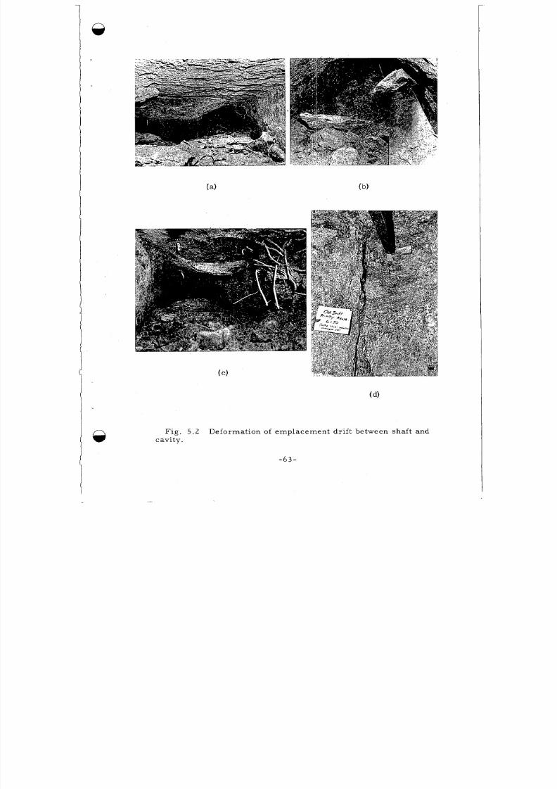
8/8/2019 pne 107 Gnome
http://slidepdf.com/reader/full/pne-107-gnome 65/92
Fi g . 5 .2 Deformat ion of emplace ment d r i f t be tween shaf t and
cavi ty .
- 6 3 -
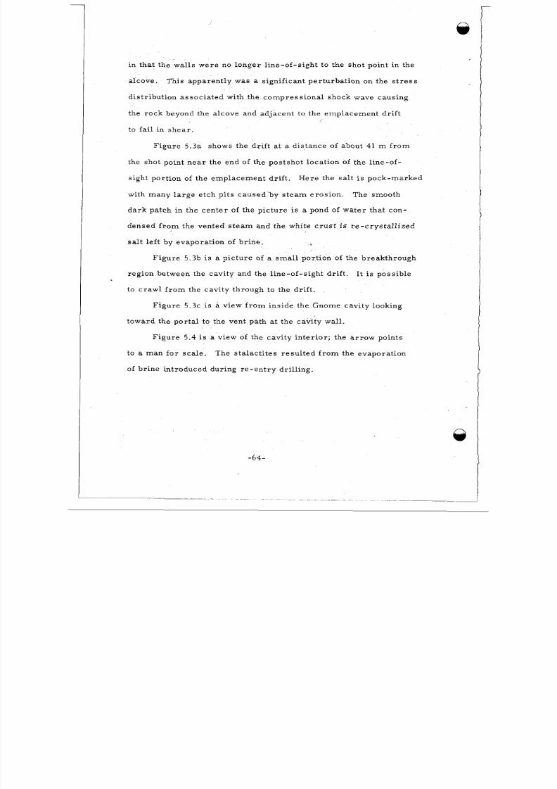
8/8/2019 pne 107 Gnome
http://slidepdf.com/reader/full/pne-107-gnome 66/92
in tha t the wal ls we re no longer l ine-of-s ight to the sho t point in the
a lcove .
d i s t r ibu t ion a ssoc ia te d with the comp ress ion a l shock wave caus ing
the ro ck beyond the a lcove and adjacent to the emp lacem ent d r i f t
to fail i n s h e a r .
This app a rent ly was a s igni ficant pe r tu rba t ion on the s t re s s
Fig ure 5.3a shows the dr i f t at a distance of about 41 m f r o m
the shot point ne ar the end of the postsh ot loca tion of the l ine-of-
s ight por t ion of the empl acem ent dr i f t .
w ith m a ny l a r g e e t c h p i t s c a us e d’ by s t e a m e r os ion .
da r k pat c h i n the c e n t e r of the p ic ture i s a pond of wa ter th a t con-
densed f ro m the vented s t ea m and the white c ru s t is r e - c r y s t a l l i z e d
salt le f t by evap ora t io n of br ine .
H e r e t he s a l t i s poc k - m a r ke d
The smooth
t
Figure 5 .3b i s a pic ture of a smal l port ion of the breakthrough
regio n be tween the cavi ty and the l ine-of-s ight dr i f t .
to c ra wl f ro m the cavi ty through to the dr i f t .
I t i s poss ib le
F ig u r e 5 . 3 ~s a view f ro m ins ide the Gnome cavi ty looking
toward the por ta l to the vent pa th at the cavi ty wal l .
F igu r e 5 . 4 i s a view of the cavi ty in te r io r ; the a r r ow poin t s
to a m a n f o r s c a le . The s t a l a c t i t e s r e s u l t e d f r o m the e va por a t i on
of b r ine in t roduced dur ing re -en t ry dr i l l ing .
-64-
Q
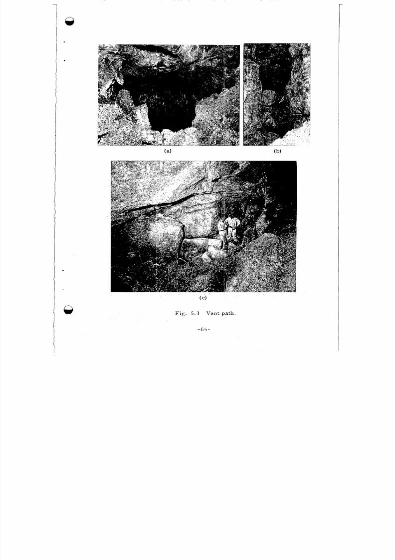
8/8/2019 pne 107 Gnome
http://slidepdf.com/reader/full/pne-107-gnome 67/92
F i g . 5 . 3 V e n t path.
- 6 5 -
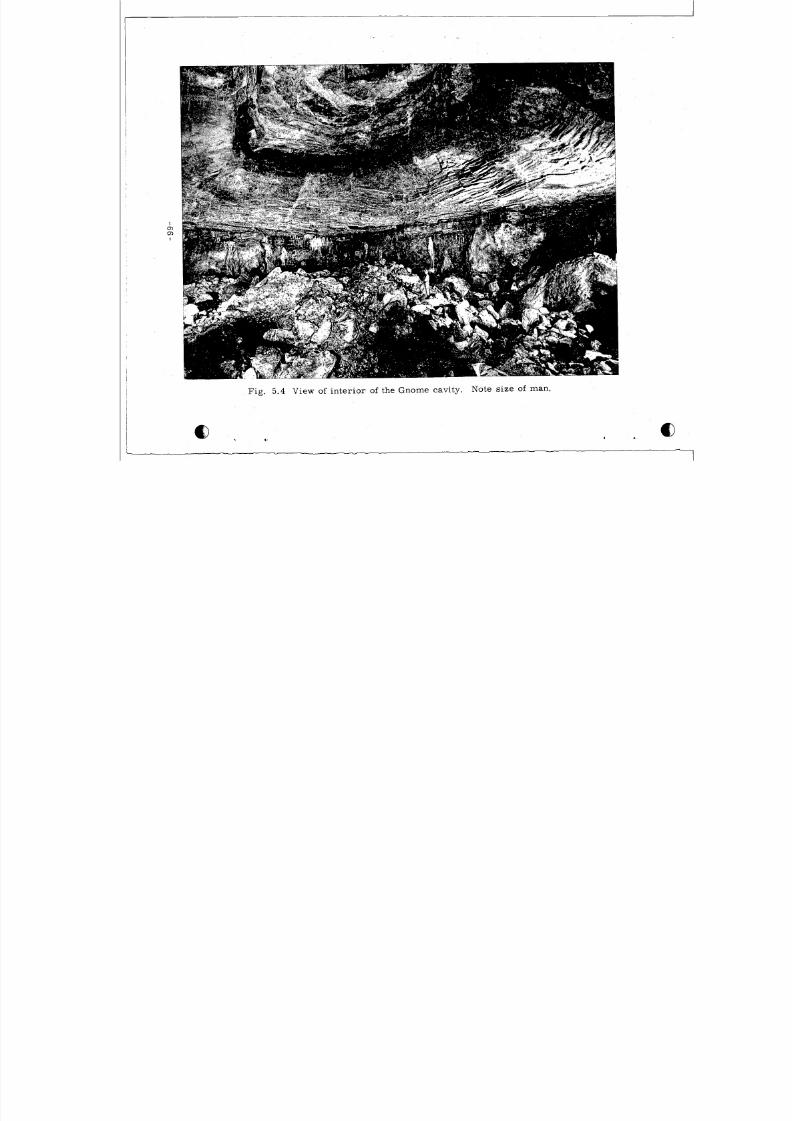
8/8/2019 pne 107 Gnome
http://slidepdf.com/reader/full/pne-107-gnome 68/92
. .
Fig. 5 .4 View of inter ior of the Gnome cavity. Note size of man.
I L 8
8/8/2019 pne 107 Gnome
http://slidepdf.com/reader/full/pne-107-gnome 69/92
*$
1% 1
CHAPTER 6
AN INTE RPR ETA TION O F THE EXPLOSSON DYNAMICS
The descr ipt i on of the environm ent c re a te d by the Gnome event
and the in te rpre ta t ion s of pro ces ses l eading to the obse rv ed re su l t s
ha ve be e n r a t he r a r b i t r a r i l y c om pa r tm e n ta l i z e d f o r t he pu r pos e s of
presen t ing the da ta.
100 m s e c , the accu mul ation of the me lt and rubble at the base of the
Actual ly, the per iod of cavi ty growth is about
cavi ty was comple ted a f te r a few minut es , and venting was comple te
in about 24 hour s . Thus , t he e nv i r onm e n t de s c r ib e d r e s u l t e d f r om
ve r y dyna m ic c ond it ions a nd t he obs e r ve d e f f e c ts a r e g r e a t l y i n t e r -
re la ted . In or de r to convey some fee ling fo r the deve lopment of the
e nv i r onm e n t obs e r ve d , a sequence of schema t ic i l lus t ra t ions have
been pr ep a re d re - cons t ru c t ing the growth of the cavi ty as a function
of t ime (F ig . 6.1). The i l lus t ra t io ns a r e , of co ur se , idea l ized;
guidance for the t emp era tu re and pr es su re of the cavi ty gas was
ob t ained f r o m c a l c u l a ti ons m a de by F r e d Se idl a nd A r tu r o Ma im on i
of LR L. These a re o rd e r -of-magni tude approxima t ions .
F i g u r e 6 . l a shows the cavi ty at about 3 msec a n d F i g . 6 . l b
1a t about 30 i n s e c .
e xpa nding p l a s m a of e x t r e m e ly h igh t e m p e r a tu r e a nd p r e s s u r e on
the o r d e r of a few mi l l ion deg rees C e ls ius and sev e ra l mi l l ion ba rs ,
The p l a sm a expands and s la ms in to the confining rock , cr.eating a
When the nu c lea r device explodes , it c r e a t e s a n
supe rs onic comp ress ion a l shock wave in tense enough to vapor ize
-67-
8/8/2019 pne 107 Gnome
http://slidepdf.com/reader/full/pne-107-gnome 70/92
1
2
3
4
5
6
7
8
, 9
10
11
12
1 3
14
15
16
LEGEND - Fig . 6.
Working Po int - center of the nuclear explos ive device .
Vaporized and ionized rock and device ma te r ia l .
Rock fused by su pe rsonic compre ss iona l shock wave.
Locat ion of roc k s t r a t a .
Outgoing com pres s ion al shock wave.
Radial c rackin g and me l t in jec t ion .
Rare fac t ion wave re turn ing f ro m ground sur face .
Zone of r oc k th at br ea k s up and "blows off" cavity s urf ace .
Rock f ro m 8 mixes wi th me l t 3 and begins to accum ula tea "puddle" at cavi ty b a s e .
Return of ra r efac t ion wave 7 lea ds to s l ight cavi ty growth
and uplift of cei ling .
F r a c tu r e s a s s oc i a te d w i th up li ft of cavi ty ce i l ing.
Extens ion of r ad ia l f r ac tu re s and fur the r m e l t in ject ion .
Bedding p lane pa r t ings in rock s t ra ta .
Probab le t im e of venting f ro m cavi ty in to emplacem entdr i f t .
Me l t and rock brecc ia - "puddle. I '
Rubble f r om ce i ling co l lapse .
Figure A B C D E F
T i me - 3 m s e c - 2 5 m s e c - 300 m s e c - 1 s e c - 1 m in - 5 m i n
CavityTemperature - 100,000 - 20,000 - 4,000 - 2,000 - 1,000 500
CC)
Cavity
( b a r s )
P r e s s u r e - 400,000 -300 -80 -40 -20 -5
-68-
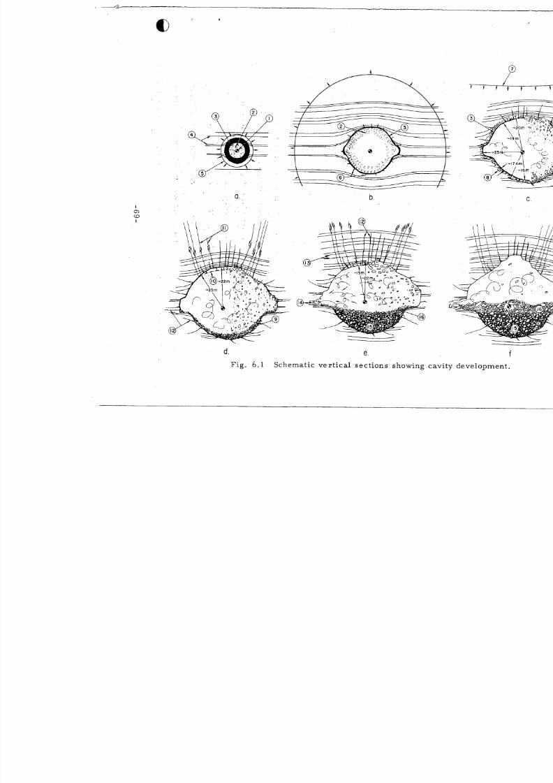
8/8/2019 pne 107 Gnome
http://slidepdf.com/reader/full/pne-107-gnome 71/92
A d
d -69-
I
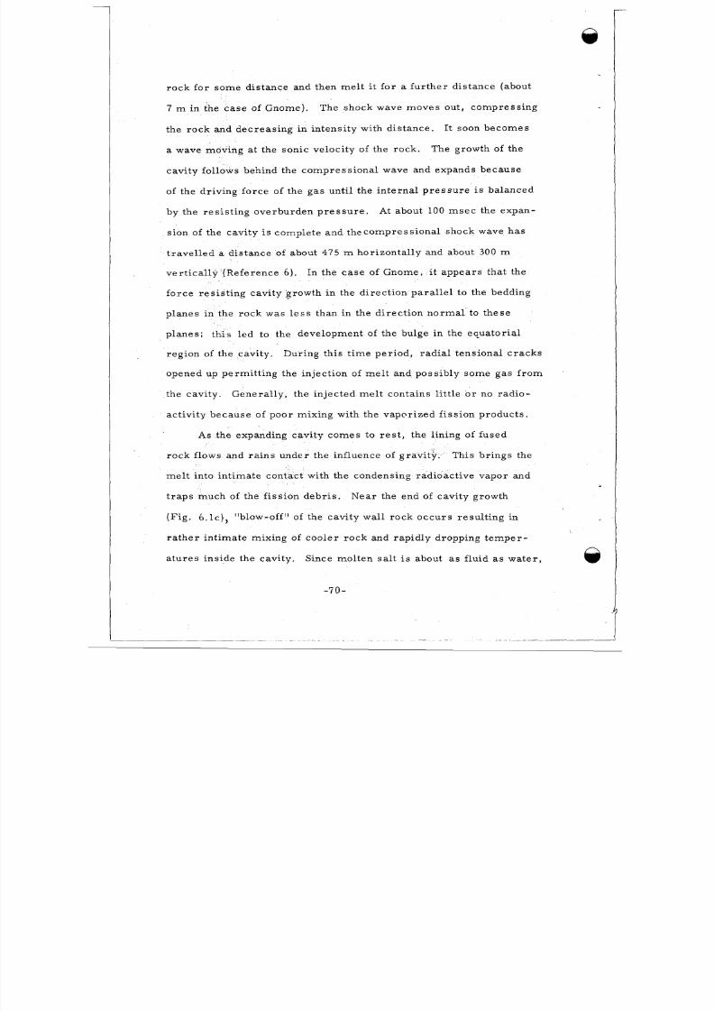
8/8/2019 pne 107 Gnome
http://slidepdf.com/reader/full/pne-107-gnome 72/92
rock for some d i s tance and then me l t it f o r a fur th e r d i s tance (about
7 m in the c as e of Gnome).
the ro ck and decr eas in g in intens i ty with dis tance .
a wave moving at the son ic velocity of the ro ck . The growth of the
cavi ty fol lows behind the c omp ress io nal wave and expands because
of the dr iving forc e of the ga s unt il the intern a l p re ss u re is balanced
by the re s i s t ing ove rburden pr es su re . At about 100 ms ec the expan-
s ion of the cavi ty i s comple te and thec om pres s ion al shock wave has
t r a ve l l e d a dis tance of about 475 m horizon ta l ly and about 300 m
ver t ica l ly (Refe rence 6 ) .
for ce re s i s t ing cavi ty growth in the d i rec t io n pa ra l le l to the bedding
planes in the rock was le s s than in the d i rec t ion no rm a l to these
plan es ; this led to the development of the bulge in the equ ator ia l
regi on of the cavity .
The shock wave mov es out , com pres s ing
It soon become s
In the case of Gnome, it app ea rs tha t the
Dur ing th i s t ime pe r iod , r ad ia l t ens iona l c ra cks
opened up perm it t in g the injec t ion of me l t and poss ibly som e gas f r o m
the cavi ty . Genera l ly , the in jec ted me l t conta ins l i t t l e o r no rad io-
ac t ivi ty because of poor mixing with the vapo r ized f iss io n pro duc ts .
As the expanding cavi ty come s to r es t , the l ining of fused
rock f lows and ra in s under the inf luence of g r a This br in gs the
me lt into int imate contac t with the condensing rad ioac t ive vapor and
t rap s much of the f i s s ion debr i s .
( F i g . 6. lc ) , "blow-off" of the cavi ty wal l rock occ ur s resul t ing in
ra ther int imate mixing of cooler rock and rapidly dropping temper -
a tu res ins ide the cavi ty .
ty .
Near the end of cavity growth
j
Since molten sa l t i s about as f lu id a s w a t e r ,
I - 7 0 -
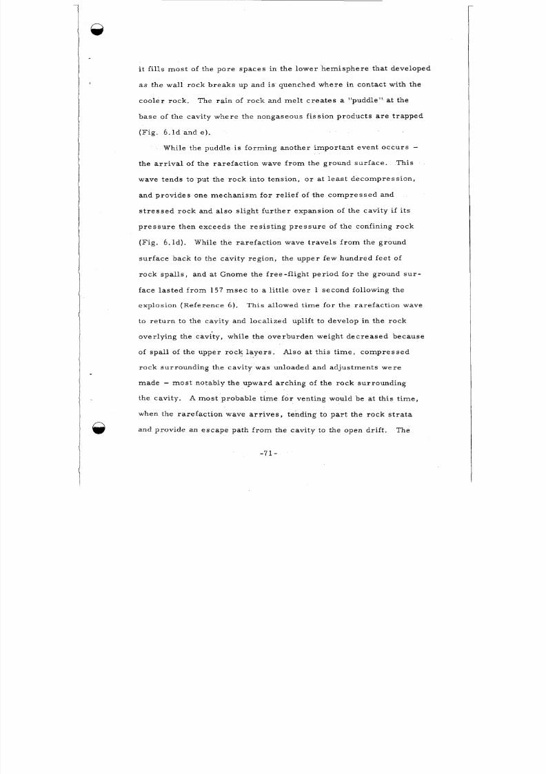
8/8/2019 pne 107 Gnome
http://slidepdf.com/reader/full/pne-107-gnome 73/92
i t f i l ls mo st of the po re spa ces in the lower hemis phe re tha t deve loped
as the wal l rock br eak s up and is quenched wh ere in contac t wi th the
c oo l e r r oc k .
base of the cavi ty where the nongaseous f i s s ion prod uc ts a r e t r apped
( F i g . 6 , l d an d e ) .
The ra in of ro ck and me l t c re a te s a l 'puddle" at the
While the puddle i s forming anothe r im por tan t event occu rs -
the a r r i v a l of the ra re fac t ion wave f r om the ground sur face . This
wave tends to put the ro ck into tens io n, o r at l e a s t d e c o m p r e ss i o n ,
and prov ides one mec han ism for re l i e f of the com pr ess ed and
s t re ss ed rock and a l so s l igh t fur the r expans ion of the cavi ty i f i t s
p re ss ur e then exceeds the re s i s t in g pr es su re of the confining rock
(Fig . 6 . l d) . While the ra re fac t ion wave t rav e l s f ro m the ground
sur f ace back to the cavi ty reg ion , the upper few hundred fee t of
rock spa l l s , and at Gnome the f ree - f l igh t pe r io d for the ground su r -
f a c e l a s t e d f r o m 157 m s e c t o a l i t t l e ov er 1 second following the
explos ion (Refe rence 6) .
to re tu rn to the cayi ty and loca l ized upl if t to develop in the roc k
over ly ing the cavi ty , while the ove rburden we ight dec r eas ed because
This a l lowed t ime f o r the ra re fac t ion wave
of spa11 of the up per ro ck la y e r s .
rock sur rounding the cav i ty was unloaded and ad jus tments w ere
m a de - mo st notably the upward archin g of the roc k surrou ndin g
the cavi ty.
w he n t he r a r e f a c t i o n w ave a r r i v e s , t end ing to pa r t the r oc k s t r a t a
and provide an e sca pe pa th f ro m the cavi ty to the open dr i f t . The
Also at t h i s t i m e , c o m p r e s s e d
A mo st probable t ime fo r venting would be at t h is t i m e ,
- 7 1 -
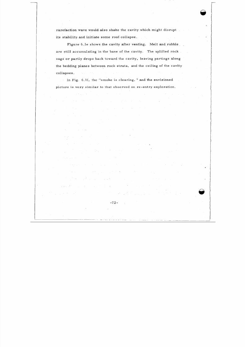
8/8/2019 pne 107 Gnome
http://slidepdf.com/reader/full/pne-107-gnome 74/92
rare fac t ion wave would a l so shake the cavi ty which might dis rup t
i t s s tab i l i ty and in i t i a te som e roof co l lapse .
F igu re 6 . l e shows the cavi ty a f te r vent ing . Melt and rubble
The uplif ted rockr e still accumula t ing in the base of the cavi ty.
sag s o r pa r t ly dro ps back toward the cavi ty , l eav ing pa r t ings a long
the bedding plan es be tween rock s t r a t a , and the ce i l ing of the cavity
col lapses .
In F i g . 6 . l f , the "smoke i s c l e a r i n g , I and the envisioned
p i c tu r e i s v e r y s imi la r to tha t obse rved on r e - e n t r y e xp lo r a ti on .
- 7 2 -
8/8/2019 pne 107 Gnome
http://slidepdf.com/reader/full/pne-107-gnome 75/92
R E FE R E N C E S
1. Hydrologic and Geologic Studies , Pr oj ec t Gnome Rep ort0
P N E - l 3 0 F , U . S. Geologic Sur vey , Sep temb er 25, 1962.
2. Hoy, R. B. and R. M. F oo se, "Ear th D efo rm a ti on f r o m a
Nuc lear Detonation in Sal t , t PNE - 109P, S tanford Resear ch
Ins t i tu t e , March , 1962 . I
3 . Randolph, P. and G. Higgins, "Various P a p er s Giving Some
E a r l y G n om e R e s u l t s , I t L aw rence R ad ia ti on L abo ra t o ry (L i ve rm ore ,
Cal i fornia ) Rept . UCID-4423, Ja nu ar y 19, 1962.
4 . Higgins , G . H . , D . E . Rawson, and W . Z. Wade,"Chemical
Reac t ions Induced by Underground Nuc lear Explos ions , I ' L aw rence
Radiat ion Lab ora t ory (L iv erm or e , Ca l i fo rn ia ) Rept. UCRL-5882 Rev . ,
196 1.
5. Nathans , M. W . , " Iso tope Pr og ra m , ' PN E -102F ( t o be
publ i shed) .
6 . W e a r t , W . D. , "Par t i c l e Motion Ne ar a Nuclear Detonat ion
in Hal i t e , PN E-l 08 P, 1961.
7 , H o lm e s a n d N a r v e r , Fie ld Drawing #F-01371 , Decem ber 27,
1961.
8 . Gard , L. M . , "Li thologic Log of t he Recover-Hole C ore ,
P r o j e c t G n o m e , " U. S. Geol. Surv . T ech . L e t t e r , Gnome 1 ,
November, 1961.
- 7 3 -
8/8/2019 pne 107 Gnome
http://slidepdf.com/reader/full/pne-107-gnome 76/92
REFERENCE S (Continued)
9 . S t e r r e t t , T . S. , "Su mm ary of D ril l ing Data fo r USGS Hole 6
and 7, P r o j e c t G n o m e, ' I U . S. Geol . Surv . Tech . L e t t e r , Gnome 14,
September , 1962.
10 . Gard , L. M. , "Some Geologic Elfe c ts of the Gnome Nucl ear
Exp los ion , " U . S. Geol. Surv . Tech . L e t te r , Gnome 15 , Oc to be r ,
1962.
11 . Te l le r ,
March , 1963.
E . , "Plow share , Nuc lea r News , 'Vol. 6 , No, 3 ,
- 7 4 -
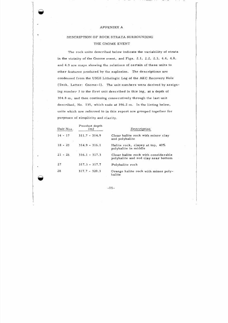
8/8/2019 pne 107 Gnome
http://slidepdf.com/reader/full/pne-107-gnome 77/92
APPENDIX A
DESCRIPTION O F ROCK STRATA SURROUNDING
THE GNOME EVENT
The rock uni t s d esc r ibed below indica te the va r iab i l i ty of s t r a t a
in the vicin ity of the Gnome ev ent , and Figs . 2 .1 , 2.2, 2.3, 4.4, 4.8,
and 4.9 ar e m ap s showing the re la t ions of ce r ta in of the se uni ts to
o the r fea t ure s produced by the explos ion .
cond ensed fr o m the USGS Lithologic Log of the AEC R ec ov ery Hole
The de s c r ip t i ons a r e
( Te c h . Le t t e r : G nom e -1 ) . The un it num be r s w e r e de r ive d by a s s ign -
ing num ber 1 to the f i r s t un it de s c r i be d i n t h i s l og , at a depth of
304.8 m , and then cont inuing consecu t ive ly through the las t uni t
de scr ib ed , No. 135, which ends at 396.2 m . In the l is t in g be low,
un i ts w h ic h a r e r e f e r r e d t o i n t h i s r e po r t a r e g r oupe d t oge ther f o r
purp oses of s impl ic i ty and c la r i ty .
P r e s h o t d ep th
( m ) De s c ription-nit Nos .
14 - 17 311.7 - 314.9 Cle a r ha l i t e rock wi th min or c lay
and polyhalite
18 - 20 314.9 - 316.1 Hal i te roc k, c layey a t top, 4070
polyhal i te in middle
21 - 2 6 316.1 - 317.3 Cle a r ha l i t e rock wi th cons ide rable
polyha l it e and red c la y ne a r bot tom
27 317.3 - 317.7 Polyhal i te roc k
28 317.7 - 320.3 Orang e ha l i te roc k with mi no r poly-
ha l i t e
-7 5-
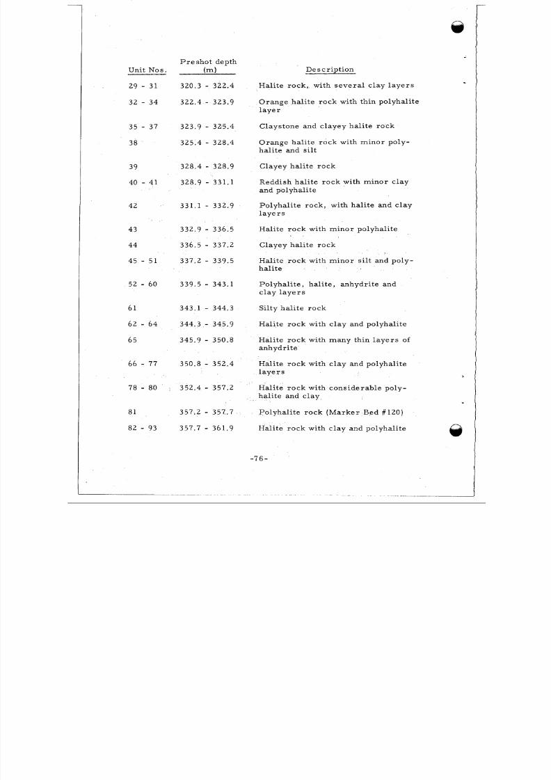
8/8/2019 pne 107 Gnome
http://slidepdf.com/reader/full/pne-107-gnome 78/92
Unit N o s .
29 - 31
32 - 34
35 - 37
38
39
40 - 41
42
43
44
45 - 5 1
52 - 60
61
62 - 6 4
65
66 - 77
78 - 80
81
82 - 93
P r e sho t depth
( m )
320.3 - 322.4
322.4 - 323.9
323.9 - 325.4
325.4 - 328.4
328.4 - 328.9
328.9 - 3 3 1 . 1
331.1 - 332.9
332.9 - 336.5
336.5 - 337.2
337.2 - 339.5
339.5 - 343.1
343.1 - 344.3
344.3 - 345.9
345.9 - 350.8
350.8 - 352.4
\ 352.4 - 357.2
357.2 - 357.7
357.7 - 361.9
Descr ip t ion
H a li te rock , w it h s ev e ra l c l ay l ay e r s
Orang e hal i te rock wi th thin polyhal ite
l a y e r
Claystone and clayey hal i te rock
Orange hal i te rock wi th minor poly-
hal i te and s i l t
Clayey hal i te roc k
Reddish hal i te roc k wi th min or c lay
and polyhali te
Polyha l i te rock, wi th hal i te and clay
l a y e r s
Hali te r oc k with min or polyhali te
Clayey hal i te roc k
Hal i te ro ck with mino r s i l t and poly-
hal i te
Polyhal i te , hal i te , anhydri te and
c la y l a y e r s
Si l ty hal i te roc k
Hali te roc k with cla y and polyhali te
Hal it e rock with many th in l ay er s of
anhydr i t e
Hali te roc k with cl ay and polyhali te
l aye r s
Hal i te roc k with conside rable poly-
hal i te and clay
Polyhal i te rock (M ark er Bed #120)
Hali te rock with clay and polyhali te
- 7 6 -
8/8/2019 pne 107 Gnome
http://slidepdf.com/reader/full/pne-107-gnome 79/92
P r e s h o t d ep th
Unit N o s . ( m )
94 361.9 - 362.3
. 95 - 98 362.3 - 366.1
9 9 - 104 366.1 - 366.9
105 366.9 - 369.6
10 6 - 107 369.6 - 370.9
108 370.9 - 374.7
10 9 - 110 374.7 - 376.4
111 - 114 376.4 - 381.6
11 5 - 120 381.6 - 385.5
121 - 123 385.5 - 389.2
124 - 126 389.2 - 390.8
12 7 - 133 390 .8 - 393.8
De s c r ipt ion
Po lyhal i te rock (M ark er Bed #121)
Orange ha l i t e rock wi th minor po ly-halite and clay
Hal i te , polyhal i te and c lay la ye rs
Orange ha l i t e rock wi th m inor po ly -
ha l i t e and c l ay
Hal i te rock wi th mi no r polyhali te
- Pink ish- gray hal i te ro ck with 3070
c l a y
Clayey hal i t e rock
Union anhydr i te b ord ere d on top and
bottom by polyhali te
Clayey ha l i t e rock wi th g r ay c l ay
seams
Orange ha l i t e rock wi th min or poly-
hal i te
Claystone and hal i te roc k
G r a y t o orange halite rock wi t h 1-270polyhali te and 5- 1070 clay
-7 7 -
8/8/2019 pne 107 Gnome
http://slidepdf.com/reader/full/pne-107-gnome 80/92
APPENDIX B
APPROXIMATE PRESHOT CHEMICAL COMPOSITION
O F THE ROCK FUSED AND VAPORIZED B Y
THE GNOME EVENT
The following perc entag es rep rese nt average va lu es obtained
f ro m chemica l ana lyses of pre shot dr i l l -ho le cor e sam ples weighted
to rep res ent the zone of fuse d and vapor ized rock. Composi te sa mp les
w e r e analyzed represent ing a sph ere of r ock surrounding the explos ion
c e n t e r of 8.5 m r a d ius .
Si 0.18570
c1 55.470
Ca 1.4070
Mg 0.6570
6.3870
s04
K
F e
Al
N a
C
H2°
1.4370
0.0470
0.07 1%
35.070
0.09470
- 1.570
- 7 8 -
8/8/2019 pne 107 Gnome
http://slidepdf.com/reader/full/pne-107-gnome 81/92
APPENDIX C
ASSUMPTIONS INHERENT IN THE TREA TME NT
O F THE PERMANENT DISPLACEMENT DATA
The equa tion used to ana lyze the pe rman ent d i sp lacement d a ta
i s : R c = (R:-R:)1/3 . This equa tion i s ba sed on the re la t ionship :
w h e r e :
R
R
= Radius of the ore t ica l cavi ty void,
= Pos t shot r ad ia l d i s tance of poin t p f r om working
C
point , and
R. = Pr esh ot r ad ia l d i s tance of poin t p f ro m working1
point.
It a s s um e s t ha t t he d i s p l a c e m e n t of m a t e r i a l i s r a d i a l f r om the w or k -
ing poin t and tha t ne i the r dens i ty changes nor fau lt ing oc cur in the
rock a s i t yie lds to the fo rc e of the expanding cavity .
t i ons a r e no t t r u e , how e ve r . Fa u lt i ng w as obs e r ve d , a nd p r oba b ly
som e pe rm anen t compac t ion of the rock , e spec ia l ly the c lay uni t s ,
d id oc c u r .
equa tion a r e only approxim a t ions .
T h e se a s s u m p -
Thu s , cavi ty rad i i ca lcu la ted by mean s of the foregoing
- 7 9 -
8/8/2019 pne 107 Gnome
http://slidepdf.com/reader/full/pne-107-gnome 82/92
.
,,PPENDIX D
CAVITY VOID, RU BB LE , AND M EL T VOLUME
CALCULATIONS
D .l EXISTING CAVITY VOID VOLUME
The ave rage p lan ime te re d a re a of th r ee ve r t i c a l sec t ions of
2the existing cavity void is 795 m .
hem isph e r ica l , the fo llowing re la t ionship ex i s t s :
Assum ing this void to be roughly
n 2 2- R = 7 9 5 m o r R = 22.6 m ,2
w he r e R i s the radiu s of the hem isp her e . The volume of the ex i s t -
ing cavi ty i s the re fore :
~ ( 2 2 . 6 ) = 24,180 m 3
3
D.2
VOID IN THE LOWER HEMISP HERE O F THE CAVITY
TOTAL VOLUME O F RUBBL E, ME LT AND INTEYSTITIAL
D.2.1 Volume of Rubble and In te rs ti ti al Void Above the
"Approximate Upper Boun dary of Melt" ( F i g . 2.2). The average
height and radius of this zone are 5.2 m and 22.9 m re spec t ive ly .
Assuming a cyl indr ica l shape , i ts volume i s
2 3~ ( 2 2 . 9 ) 5.2) = 8,560 m
D.2.2 Volume of Melt , Rubble , and Inter s t i t ia l Void Below
the "Approximate Upper Boun dary of Melt . I '
ima te ly a sph e r ica l segment with an ave rage he ight of 12.2 m and
This zone i s approx-
-8 0 -
8/8/2019 pne 107 Gnome
http://slidepdf.com/reader/full/pne-107-gnome 83/92
average r ad ius at the upper m el t boundary of 18.3 m . I t s volume
n
can be ex pre sse d as fo llows , using the form ula fo r volume of a
sphe r i ca1 se gmen t .
rr 2 2 3V = 12.2 [3(18.3 ) + (12.2) 3 = 7,360 m
Total volume of cavity ru bble, melt , and in te rs t i t ia l void i s
3there fo re the sum of A and B o r 15 ,920 m .
D.3 VOLUME AND MASS O F M ELT
The averag e percenta ge of mel t encountered by the underground
dr i l l ho les is 2770.
of t he sphe r i ca l segm ent in D.2.2, t he r esu l t ing me l t vo lume is 1,980
m .
Using th i s pe rcen tage to r e p re sen t the mel t con ten t
3The ave rage bulk densi ty of th is m el t i s 1 .6 g/cc. Th e r e f o r e ,
i ts m a s s i s :
3 6( 1 ,6 0 o k g / m ) ( 1 ,9 8 0 m 3 ) = 3.2 x 10 kg
D . 4 TOTAL VOID VOLUME CREATED B Y THE DETONATION
D.4.1 Void Volume Repr ese nte d by the Po ro si ty of the Mel t ,
The porosi ty of t he me l t i s approximately 27% (bulk dens i ty = 1.6,
na tu ra l s t a t e dens ity = 2.2) and ' th e to ta l volume of the me l t i s 1,980
m . The re fo re i t s ves i cu la r void vo lume i s :
3 3(0.27)(1,980 m ) = 540 m
D . 4 . 2 Void Volume Rep resent ing the In ter s t i t ia l Po re Space
in the Rubble. Assum ing a po ro si ty of 2870 fo r the rub ble (excluding
the me l t which fills up a la rge amount of that s pa ce ) the to ta l void
-81-
8/8/2019 pne 107 Gnome
http://slidepdf.com/reader/full/pne-107-gnome 84/92
volume of the rub ble pile is :
3 3(0.28)(15,920 m ) = 4,460 m
A poro s i ty of 28% was chosen because the Hardha t event in grani te
produced a rubble-f i l led chimney with th is poro s i ty . Subtract ing
the volume of the melt (1,980 m 3 ) , the resu lting volume of rubble
3pore space i s 2 ,480 m .
Total void volume cr ea te d by the detonation i s t h e r e f o r e t he
su m of the following volum es:
Cavi ty
Mel t pore volume^
3
3
24,180 m
540 m-
Rubble po re volume 2,480 m 5
27,200 m 5
D.5 TOTA L VOLUME AN D MASS O F RUBBLE
The volume of the rub ble , obtained by subt racti ng the po re
volurne of the rubble (2,480 m ) and me l t , including pore space ,3
3( 1,980 m ) f r o m the to ta l volume of the rubble p i le ( 15,920 m 3) i s
311,460 m .
Assuming a na tu ra l s tat e bulk density of 2 .2 g/c c, the rubble
m a s s i s : 6
3(2200 kg /m )(11,460 m 3) = 25.2 X 10 kg
- 8 2 -
8/8/2019 pne 107 Gnome
http://slidepdf.com/reader/full/pne-107-gnome 85/92
APPENDIX E
RUBBLE DISTRIBUTION
The tota l volume of rub ble , exc lus ive of inte rs t i t i a l void, i s
3 3roughly 11,460 m , Of this volume, approx imate ly 5,300 m i s
in t ima te ly a s soc ia ted wi th the me l t in the lower hemi sph e re of the
3cavi ty. The remainin g 6,160 m blankets this region and conta ins
ve r y l i tt l e m e l t .
The ave rage theore t ica l cavi ty rad ius of the lower hemisp he re ,
de fined by pe rmanent rock d i sp lacem ents , i s approxima te ly 16.2 m ,
and that defined by the extent of me lt i s 17.4 m .
1.2 m in these rad i i may rep res en t the th ickness of the she l l of ro ck
"blown off" the cavi ty wal ls a t ea r l y t im es . Assum ing this thickness
to be roughly uniform around the cavi ty and assum ing a cavi ty rad iu s
p r i o r to "blow-off" of 18.7 m ( the radius of a sp her e of approxim ate ly
327 ,200 m vo lu me ), the volume of the sh el l of blown-off ro ck i s
5 , 6 0 0 m . Since this volume i s v e r y c l o s e to tha t of the rubble
The dif feren ce of
3
asso c ia te d with me l t , i t i s sug ges ted that the bulk of the ru bble i n
this region w as blown off the c avi ty wal ls .
The average radi us of the upper he mi sph ere of the cavi ty i s
approxima te ly 22.9 m .
18.7 m in this region i s a s s u m e d .
rad ii re pr es en ts the thickn ess of both coll apse d and blown-off rock .
Assuming a thickness of 1..2 m was blown off ( a s de t e r m ine d p r e v ious ly ) ,
a 3-m -thick she l l of rock col l apsed f r om the roof of the cavi ty.
A maxim um ea r ly - t im e cavi ty rad ius of
The 4.2-m dif ference in thes e
Cavity
-83-
8/8/2019 pne 107 Gnome
http://slidepdf.com/reader/full/pne-107-gnome 86/92
prof i les suggest this she l l extended to an e levat ion of approxim ate ly
682 m o r 7 .9 m above the working point.
col lapsed r ock can be a pproxim ated by the dif feren ce in volume of
sphe r ica l se gme nts with respe ct ive he ights of 13.7 m (21.6 les s 7.9
m ) and 10.8 m (18.7 le s s 7.9 m ) , a nd ba s a l r a d i i of 25 m ( s c a l e d
The volume of this she ll of
f r o m Figs . 2 .1 and 2.2) and 22.1 m .
ro ck volume of 5,850 m 3 , which co mp are s favorab ly with the volume
of r oc k overlyin g the me lt zone.
Th i s r e s u l t s i n a col lapsed
-84-
8/8/2019 pne 107 Gnome
http://slidepdf.com/reader/full/pne-107-gnome 87/92
TECHNICAL REPO RTS SCHEDULED FO R ISSUANCE
BY AGENCIES PAR TICI PATI NG I N PRO JECT GNOME
AEC REPORTS
AGENCY
L R L
L R L
ORNL
L R L
L R L
L R L
L R L
sc
SRI
USC&GS
SRI
L R L
L R L
LASL
EG&G
WES
USWB
H&N, INC
REPORT NO.
PNE-101
102
103
104
105
106
107
10 8
109
110
1 1 1
112
11-3
114
115
116
126
127
SUBJECT OR TIT LE
Pow er S tud ies
I s o t o p es P ro g ram
Des ign of Sequenced Gas Samplin g App arat us
Close-In Shock Studies
Stress M eas u rem en t s with Pi ezo e l ec t r i c C ry s t a l s
P o s t -Shot Tempe ra tu r e and Radiation Studies
Geologic Studies of the Tunnel and Shaft
Par t ic l e Motion near a Nuc lear Detonation in Hal i te
E a r t h Defo rm a ti o n f r o m a Nucl ear Detonation in
Sal t
Se i s m i c M eas u rem en t s f ro m a Nuclear Detonation
i n Ha l i te
In te rmed ia te - Range Ear th Motion Me asure ments
An Invest igat ion of P oss ible Chem ical React ions
and Phase Trans i t ions Caused by a Nuclear Explosive
Shock Wave
Resonance Neu t ron Act iva t ion Measur emen ts
S y m m e t r y of F i s s i o n i n U235 t Individual Resonances
Timing and F i r in g
Des ign , Te s t and F ie ld Pumping of Grou t Mix tu res
Pr el i mi na ry Report of Weather and Surface Radia-
t ion Pred ic t io n Act iv i t i es fo r Pr o jec t Gnome;Fi na l Analysis of Weather and Radiat ion Data
Pre-Sho t and Pos t -Sho t S t ruc tu re Survey
8/8/2019 pne 107 Gnome
http://slidepdf.com/reader/full/pne-107-gnome 88/92
AGENCY RE PO RT NO.
RF B, INC P N E - 128
sc
USGS
FAA
USPHS
R EE C o
USBM
129
130
131
132
133
134
SUBJECT OR TITLE
Summ ary of Predic t ion s and Com par i son wi thObs erve d Effec ts of G nome on Pub lic Safety
Monitoring Vibrations at the US Bo rax and
Chemica l Company Potash Ref ine ry
Hydrologic and Geologic Studies
Fe de ra l Avia t ion Agency Ai r sp ace Cl osu re
Off-Site Radiological Safety Report
On-Si te Radiologica l Safe ty Repor t
P r e and Pos t-Shot Mine Examinat ion
8/8/2019 pne 107 Gnome
http://slidepdf.com/reader/full/pne-107-gnome 89/92
AGENCY
EG&G
S T L
sc
USGS
sc,
EG&G
SGC
ERDL
SFU
SFU
ERDL
TI
USGS
E G& G
C&GS
GeoTech
USGS
ARA
DOD REPORTS
SUBJECT OR TIT LE
Tech nical Photography of S urfa ce Motion
Shock Spec t ru m Measurem ents - Reed Gage
Microbarographic Measurements
Study of El ec tr ic and Magnetic Effe cts
Elec t ro magne t ic Waves f r om Underground
Detonations
Subsur face Elec t rom agne t ic Waves
Ea r th C ur r e n t s f r o m Unde rg r ound De tona tions
Reflec tance Stitdies of V egetation D ama ge
Visu al and Photographic On-Site Inspection
Seismic Noise Monitor ing
Soil Density Studies
Geochemica l and Radia t ion Surveys
Solid State Changes in Rock
Radon Studies
In te rmedia te Range Se ismic Measurements
Long Range Se ismi c Measurem ents
Ae r om a gne ti c a nd Ae r o r a d iom e t r i c S ur ve ys
On-Site Resis t ivi ty and Self Potentia l Mea sure men ts
-87-
8/8/2019 pne 107 Gnome
http://slidepdf.com/reader/full/pne-107-gnome 90/92
ABBREVIATIONS FOR TECHNICAL AGENCIES
ARA
EG&G
ERDL
GeoTech
LASL
L R L
sc
SGC
SR I
ST L
TI
USC&GS
USGS
WES
FAA
H& N, Inc.
RFB, Inc.
REECo '
USBM
USPHS
USWB
Allied Researc h Assoc ia tes Inc . , Bos ton
E d g e r t o n , Ge rm es h au s en , an d Gr i e r , Inc . ,Boston, Las Vegas , and Santa Ba rba ra
USA C of E Engineer Rese arch and Develop-
m en t L ab o ra t o r i e s , Ft. Belvo i r
The Geo techn ica l Corpora t io n , Gar land
Los Alamos Scien ti f i c Labo ra to r ies , LosAlamos
L awren ce R ad ia t io n L ab o ra t o ry , L i v e rm o re
Sandia Cor pora tion , Albuque rque
Space-Genera l Corpora t ion , Glendale
Stanford Rese arch Ins t i tu te , Menlo Pa r k
Space Technology Lab ora tor ies , Inc. ,Redondo Bea ch
Texas Ins t rum ents , Inc. , Dallas
Coa st and Geodetic Su rve y, Washington, D. C.and Las Vegas
Geological Survey, Denver
USA C of E Waterways Exper imen t S ta t ion,J ack s on
Fe de ra l Aviat ion Agency, Sal t Lake City
Holmes and Na rve r , Inc . , Los Angeles
R. F.' B ee rs , In c . , A l ex an d r ia
Reynolds E lec tr ic al and Enginekring CO.,Las Vegas
U . S. Bu rea u of Mi nes, Washington, D. C.
U. S. Publ ic Heal th Serv ice , Las Vegas
U . S. Weather Bureau, Las Vegas
-88-
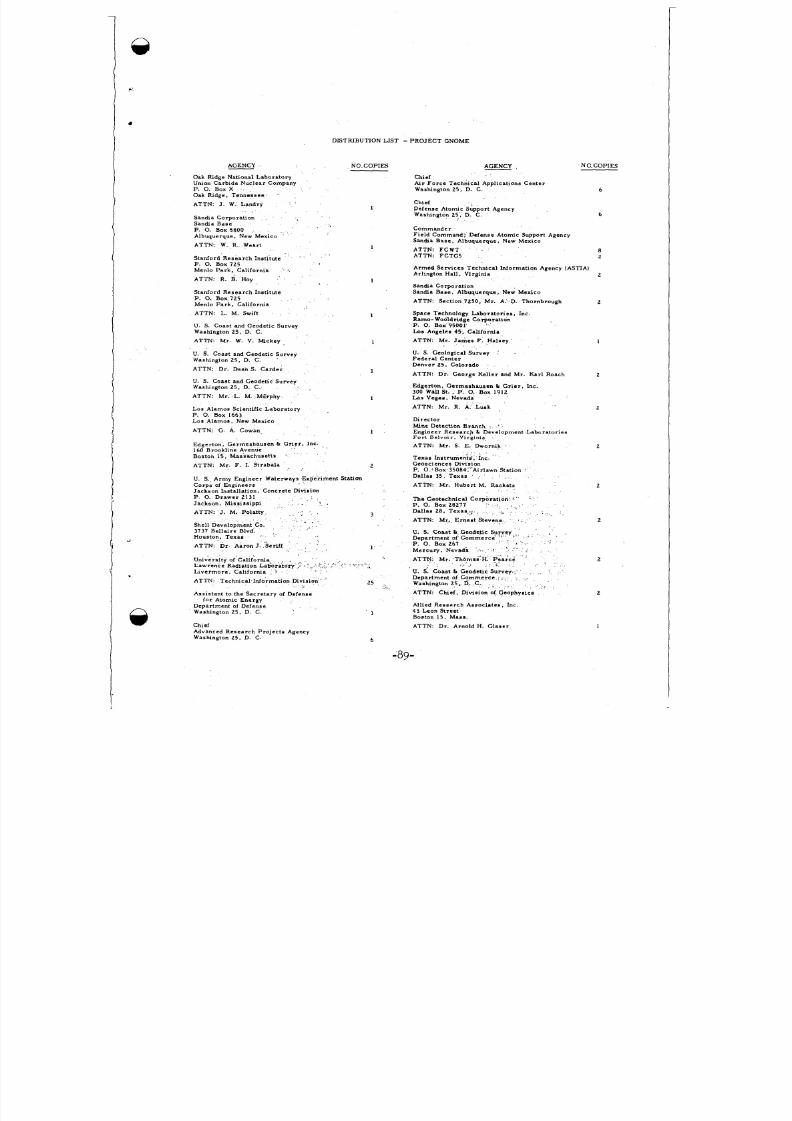
8/8/2019 pne 107 Gnome
http://slidepdf.com/reader/full/pne-107-gnome 91/92
AGENCY
Oak Ridge National LaboratoryUnion Carbide Nuclear Company
P. 0. Box X
Oak Ridge. Te nnes see
ATTN: J. W. Landry
Sanma Corporat ionSandia Base
P. 0. Box 5800
Albuquerque , New Mexico
ATTN: W. R. Weart
S tanford Research Ins t i tu teP. 0. Box 725Menlo Park , Cal ifornia -.ATTN: R. B. Hoy
Stanford Research InstituteP. 0. Box 725Menlo Par k , Cal ifo rnia
ATTN: L. M. Swift
U S. Coast and Geodetic SurveyWashington 25, D. C.
ATTN: Mr. W. V. f i c k e y
U. S. Coast and Geodetic SurveyWashington 25, D. C. ’
ATTN: Dr. Dean S. C a r d e r
U S. Coast and Geodetic SurveyWashington 25, D. C.
ATTN: Mr. L. M. Miirphy
Los Alamos Scient if ic LaboratoryP. 0. Box 1663
L o s Alamos, New Mexico
ATTN: G. A. Cowan
DISTRIBUTION LIST - PROJECT GNOME
NO. COPIE S
1
1
1. .
1
Ed g er to n , G er mes h au s en & C r ie r . I n c160 Brookline Avenue
Bos ton 15, Massachuset t s
ATTN. Mr. F. I. Strabala 2
U. S. Army Engineer Waterways Experi ment StationC o r p s oi En g in ee r s
Jackson Ins tal la t ion , Con crete Dins lonP 0. D r a w e r 2 1 3 1
Jackson, Miss iss ippi
ATTN: J. M. Polat ty
Shell Development Co.3737 Bella lre Blvd.
Hous ton, Texas
ATTN. Dr. Aaron J. Serif1 1
3
I .
University of Califor maLawrence Radiat ion La6ora tory ‘ ’ ,Liv e r mo r e , C a l i fo r n ia
ATTN Technical Information &vision 2 5
Assis tant to the S ecre tary of Defensefo r Atomic Energy
Depar tment of DefenseWashington 25, D. C.
Chief
Advanced Researc h Pro jec ts AgencyWash ngto n 25. D. C.
1
AGENCY NC.COPIES
ChiefAir For ce Technical Applicat ions Ce nter
Washington 2 5 , D. C 6
Chief
Defense Atomic Support AgencyWashington 2 5 . D. C 6
C o mman d erFiel d Command: Defense Atomic Support AgencySandia Base. Albuquerque, New Mexico
ATTN: FCTG5 2ATTN: FCWT 8
Armed Services Technical Information Agency (ASTIA)
Arl ington Hall , Virgima 2
Sands Corporat ion
Sa na a Base . Albuquerque, New Mexico
ATTN: S ection 7250, Mr. A. D. Thorn brough 2
Space Technology Laborator ies , Inc
Ramo-Wooldr idge Corporat ionP. 0. Box 95001
L o s Angeles 4 5 , California
ATTN: Mr. James F. Haleey I
U. S. Geological SurveyF e d e r a l C e n t erDenver 2 5 . Colorado
ATTN: Dr . George Keller and Mr. Karl Roach 2
Edger ton, Germeshausen & G r ie r , I n c .300 W a l l St . , P. 0. Box 1912Lap Vegas. Nevada
ATTN: Mr. R. A. Lu sk 2
& r e c t o r
W ne Detection Branch I
Engineer Research & Development LaboratonesF o r t B e l v oi r . Virginia
ATTN: Mr. S E. Dwornik 2
P. 0 )Box 35084, Airlawn Station
Dallas 35 Texas
ATTN: Mr. Hubert M. Rackets
The Ceotechnical CorporP. 0. Box 28277Dallas 28 , Tex as
ATTN: Mr. Ern es t Stevens 2
2
C. S. Coas t L Geodetic Survey, 4 -
Depa rtme nt of Commerc; ’ I
P. 0. Box 267
Mercury , Nevada
ATTN: Mr. Thomas’H. Pea rke 2
U. S. C o as t & C eo d e tx S u r v ev
- , 4
Depar tmen t of Comme rce .Washington 25, D. C.I
ATTN: Chlef, Din sio n of Geophysics 2
All ied Research Associates . Inc.43 Leon S treetBoston 15, Mass.
ATTN: Dr. Arnold H. G l a s c r
6
1
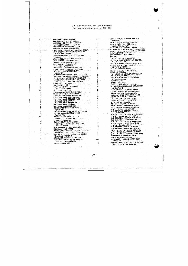
8/8/2019 pne 107 Gnome
http://slidepdf.com/reader/full/pne-107-gnome 92/92
DISTRIBUTION LIST - PROJECT GNOME
(TID - 4500(40th Ed.) Category U C - 35)
9 . *
1
1
1
1
1
1
6
1
2
1
1
1
2 1
1
1 1
1 1
3 2
1
2 1
12
1 1
i
1 1
1
1 1
1
1
1
1
25
1 1
1
* ’ , 3 .
AREROEEN PROVING GROUNDAEROJET-GENERAL CORPORATION
AIR FORCE ~NST~TUTEF TECHNOLOGY
AIR FC?CE WEAPONS LABORATORYALBUOUERQUE OPERATIONS OFFICEARGONNE NATIONAL LABORATORY
j ARkY F F W C .H NUCLEAR CRATERING GROUP
ARMY ENGINEERRESEARCHANDDEVELOP-
ARMY ENGINEER WATERWAYS EXPERIMEN T
HENT LABORATORIES
STATICNARMY MATERIALS RESEA9CH AGEtlCY
4RHY MA TF PIF L COMHAI40 (ON-RE)
1
1
2
1
f 1
1
5 1
1
1
1
ARMY MATERIEL COMMANP (NA) 1 ARMY M4T EPI€L CtMMANO (Hp)
7 ArlMY ?IATICK L4BOPATORIES 1
ARMY NUCLEAR DEFENSE LABORATORY 1 ATOMIC ENERGY COMMISSION, B ETHES DA1 AFC SCIECTIFIC REPRESENTATIVE.1 ARGENTINA 1
AEC SCIENTIFIC REPRESEEITATIVE. BELGIUM 1
AEC SCIEVTIFIC REPRESENTATIVE, ENGLAND 5
AEC SCIENTIFIC REPRESENTATIVE, FRANCE 1 AEC SCIENTIFIC REPRESENTATIVE, JACAN 1
ATOMIC ENERGY COMMISSION, WASHINGTONATOMICS~NTERNATIONAL . 1
1 2
AV CP CO RPO RAT IGIJEATTELLE MEMOR14L IHSTITUTE
EATTELLE-NORTHWESTBEERS (RO LAN D F.), INC.
P;€!tS(POLAhD F.), INC., LAS VEGAS
BLUMC (J9HN A, ) AYD ASSOCIATESBROOKHAVEY NATIO HAL LABORATORY
BUREAU OF MINES. BARTLESVIL LEBUREAU OF MINES, COLLEGE PARKBUREAU OF MINES, LARAMIE
BUREA U OF MINES, WASHINGTON
BUREA U OF SHIPS (CODE 1500)
DEFEN SE ATOMIC SUPPORT AGENCY,
DEFENSE ATOMIC SUPPORT AGENCY, SANDlA
DEFEN SE ATOMIC SUPPORT AGENCY,
DIVISION OF PEACEF UL NUCLEAR
DU PONT COMPANY, AlKENDU PONT COMPANY, WlLMlNGTON
EPGERTOFI. GERLESYAUSFN, AND CRIER.
B U R E A U OFN A V A L WE A P ON S
LIVERMORE
WASHINGTON
EXPLOSIVES WASHINGTON
IYC., L AS VEGAS
5
4
1
1 1
1
1
1
1
MUESFR, RUTLEDGE, WENTWORTH AND
N4 54 .IANr(ED SPACECRAFT CENTER
NASA SCIENTIFIC AND TECHNICALINFORMATION FACILITY ’
NATION AL AGRICULTURAL LIBRARY‘NATIONAL RE4CTOR TESTING STATION (PPco)NAVAL RADIOLOGICAL DEFENSE LABORATORY
NEVADA OPERATIONS OFFICENEW YORK OPERATIONS OF FICE
NRA. INC.CAI( ZlbGE CPERATlChS OFFICE
OFFICE OF ASSISTANT GENERAL COUNSEL
OFFICE OF NA VAL RESEARCH (CODE 422)
JFFlCE OF T H t CH lFF O F ENGINEERSOHIO STATE UNIVEHSITY
PETR OLtU M CONSULTANTSPHYSICS INTERN ATIONA L COMPANYPICATINNY ARSENAL
JOHNSTON
FOR PATENTS (AEC)
-
POWER REACTOR DEVELOPMENT COMPANYPUBLIC HEALTH SERVICE
PUBL IC HEALT H SERVICE, LAS VEGAS
KADIOPTICS, INC.PURDUE UNIVERSITY
RAN0 CORPORATIONRESEARCH ANALYSIS CQRPORATION
REYNOLDS ELECTRICAL AND ENGINEERING
$AN FRANCISCO OPERATIONS OFFICESANOIA CORPORATION, ALBUQUERQUESANOIA CORPORATIOH, LIVERMORESAVAW AF: RIVER OPERATlOFlS OFF ICE
SCkOOL OF AEROSPACE MEDICINE
SOUTHWEST RESEARCH INSTITUTESTANFOP[: r:ESL_ACC:! I# STI iU T E
STRATEGIC AIR COMMANDTENNESSEE VA LLE Y AUTHORITYUNION CARBIDE CORPORATION (ORGDP)UNlCN CARBIDE CORPORATION (ORNL)
USAF HEADQUARTERS (AFTAC )U. S. COAST AND GEODETIC SURVEY,
COMPANY, INC.
SAN FRANCISCOU. S. GEOLOGICAL SURVEY, ALBUQUERQUE
U. 3 . GEOLOGICAL SURVE Y (NOLAN)
U. 5. GEOLOGICAL SUSVEY, DENVER
U. 5 . GEOLOGICAL SURVEY, MENLO PARK
U. 5. GEOLOGICAL SURVEY, WASHINGTONU. 5 . MISSION TO THE INTERNATIONAL
U. 5 . WEATHER IUKE AU, LAS VEGAS
,ATOMIC ENERGY AGENCY
.