
Plastic Welding with TRIAC ST - hotairtools.com · 2 Plastic Welding with the Welding Tool TRIAC ST...
8
Plastic Welding with TRIAC ST PLASTIC WELDING
Transcript of Plastic Welding with TRIAC ST - hotairtools.com · 2 Plastic Welding with the Welding Tool TRIAC ST...
Plastic Welding with TRIAC ST
PLASTIC WELDING
2
Plastic Welding with the Welding Tool TRIAC ST
AImost every motor vehicle built today has components made froma variety of plastics. Bumpers, grilles, spoilers, light, surrounds andeven complete body panels enable designers to enhance aerodyna-mic styling and cosmetic appeal while retaining impact resistanceand eliminating corrosion.
Plastic offers the structural strength of steel by virtue of its greaterelasticity. Minor impacts that could deform steel beyond repair canbe absorbed by plastic. Where damage is incurred it is capable ofrepair by welding with no loss of component strength.
Cracks, splits, warping and even the loss of material can be remedied with the aid of the Leister TRIAC ST hot-air welding equipments. Where a steel component, with the equivalent damage, would be renewed at some cost, the repair of the plastic part can save time and expense, particularly when winter accident periods make great demands of the repairer's parts stock.
Welding plastics does not produce fumes when the correct procedureis followed. A plastic component can be quickly restored to an ‘asnew’ condition without the need for fillers or special treatments. Thecombination of welding and the recommended repaint procedures willshow no trace of a repair that should last the life of the vehicle.
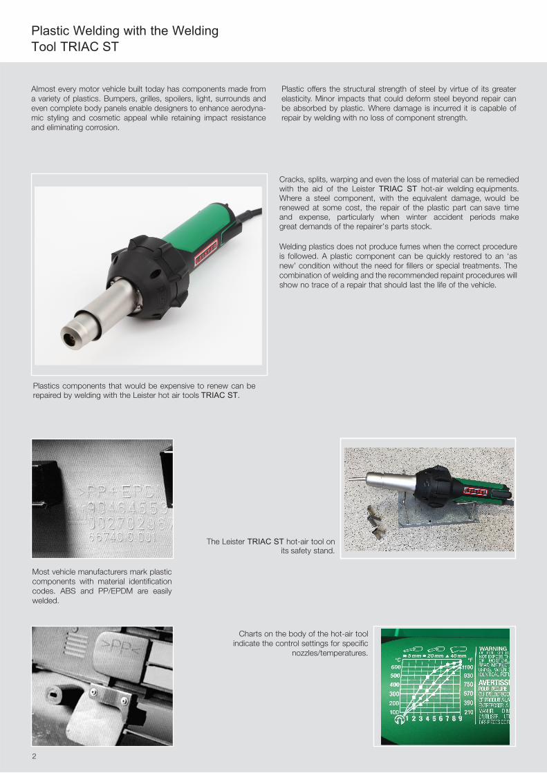
Plastics components that would be expensive to renew can be repaired by welding with the Leister hot air tools TRIAC ST.
Most vehicle manufacturers mark plasticcomponents with material identificationcodes. ABS and PP/EPDM are easilywelded.
The Leister TRIAC ST hot-air tool on its safety stand.
Charts on the body of the hot-air toolindicate the control settings for specific
nozzles/temperatures.
2
2
Welding defects
Welding dressing
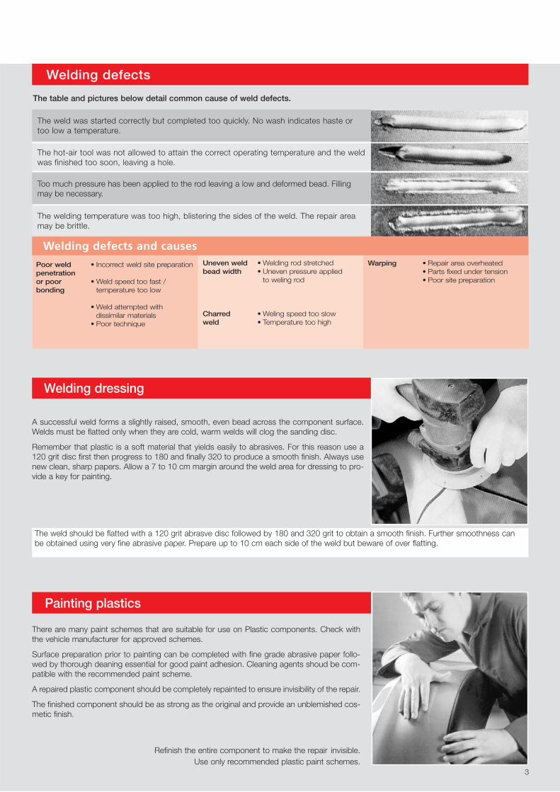
The table and pictures below detail common cause of weld defects.
The weld was started correctly but completed too quickly. No wash indicates haste ortoo low a temperature.
The hot-air tool was not allowed to attain the correct operating temperature and the weldwas finished too soon, leaving a hole.
Too much pressure has been applied to the rod leaving a low and deformed bead. Fillingmay be necessary.
A successful weld forms a slightly raised, smooth, even bead across the component surface.Welds must be flatted only when they are cold, warm welds will clog the sanding disc.
Remember that plastic is a soft material that yields easily to abrasives. For this reason use a120 grit disc first then progress to 180 and finally 320 to produce a smooth finish. Always usenew clean, sharp papers. Allow a 7 to 10 cm margin around the weld area for dressing to pro-vide a key for painting.
The weld should be flatted with a 120 grit abrasve disc followed by 180 and 320 grit to obtain a smooth finish. Further smoothness canbe obtained using very fine abrasive paper. Prepare up to 10 cm each side of the weld but beware of over flatting.
Painting plastics
There are many paint schemes that are suitable for use on Plastic components. Check withthe vehicle manufacturer for approved schemes.
Surface preparation prior to painting can be completed with fine grade abrasive paper follo-wed by thorough deaning essential for good paint adhesion. Cleaning agents shoud be com-patible with the recommended paint scheme.
A repaired plastic component should be completely repainted to ensure invisibility of the repair.
The finished component should be as strong as the original and provide an unblemished cos-metic finish.
Refinish the entire component to make the repair invisible. Use only recommended plastic paint schemes.
The welding temperature was too high, blistering the sides of the weld. The repair areamay be brittle.
3
Poor weld • Incorrect weld site preparationpenetrationor poor • Weld speed too fast /bonding temperature too low
• Weld attempted withdissimilar materials
• Poor technique
Uneven weld • Welding rod stretchedbead width • Uneven pressure applied
to weling rod
Charred • Weling speed too slowweld • Temperature too high
Warping • Repair area overheated• Parts fixed under tension• Poor site preparation
Welding defects and causes
2
Correct mating between the welding rod and the material occurs when the rodis seen to soften and the new rod moves down the nozzle feed. As the rodmelts into the groove two smooth continuous ridges will appear at the edges,accompanied by a slight wash at the sides of the weld. Do not move too fast,failing to create a wash, nor too slowly, overheating and even scorching ordistorting the plastic.
When the weld has been completed, remove the hot-air tool, sliding the nozzleoff the remaining welding rod. Once cool, the unwelded rod end is cut off asclose to the weld as possible.
The completed weld appears as a smooth continuous line with the wash stillvisible alongside it, confirming that the rod has welded successfully with thecomponent.
During the welding, previously unseen cracks may open up. These are notnew but impact cracks that have been present since the initial damage. Thesemust be treated and welded as any other crack damage.
lf the weld is successful, reinforcement welds can be added to the reverse ofthe material across the axis of the repair. The same preparation and weld oper-ations apply.
The weld should-be a slightly raised, largely smooth, continuous bead.
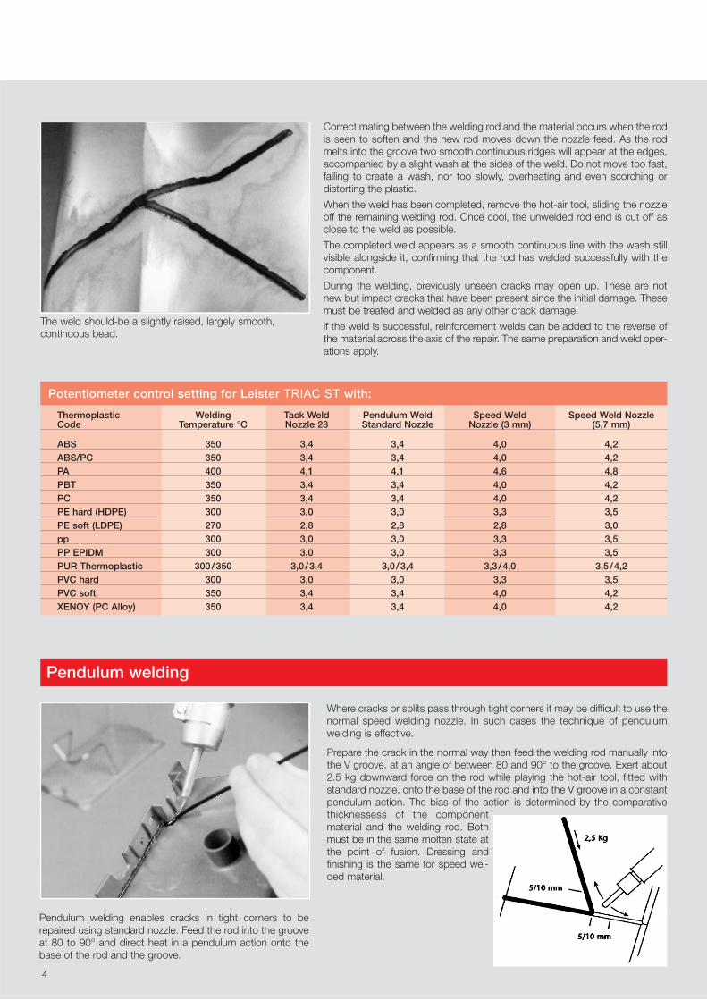
Pendulum welding enables cracks in tight corners to berepaired using standard nozzle. Feed the rod into the grooveat 80 to 90° and direct heat in a pendulum action onto thebase of the rod and the groove.
Thermoplastic Welding Tack Weld Pendulum Weld Speed Weld Speed Weld NozzleCode Temperature °C Nozzle 28 Standard Nozzle Nozzle (3 mm) (5,7 mm)
ABS 350 3,4 3,4 4,0 4,2ABS/PC 350 3,4 3,4 4,0 4,2PA 400 4,1 4,1 4,6 4,8PBT 350 3,4 3,4 4,0 4,2PC 350 3,4 3,4 4,0 4,2PE hard (HDPE) 300 3,0 3,0 3,3 3,5PE soft (LDPE) 270 2,8 2,8 2,8 3,0pp 300 3,0 3,0 3,3 3,5PP EPIDM 300 3,0 3,0 3,3 3,5PUR Thermoplastic 300/350 3,0/3,4 3,0/3,4 3,3/4,0 3,5/4,2PVC hard 300 3,0 3,0 3,3 3,5PVC soft 350 3,4 3,4 4,0 4,2XENOY (PC Alloy) 350 3,4 3,4 4,0 4,2
Potentiometer control setting for Leister TRIAC ST with:
Pendulum welding
Where cracks or splits pass through tight corners it may be difficult to use thenormal speed welding nozzle. In such cases the technique of pendulumwelding is effective.
Prepare the crack in the normal way then feed the welding rod manually intothe V groove, at an angle of between 80 and 90° to the groove. Exert about2.5 kg downward force on the rod while playing the hot-air tool, fitted withstandard nozzle, onto the base of the rod and into the V groove in a constantpendulum action. The bias of the action is determined by the comparativethicknessess of the componentmaterial and the welding rod. Bothmust be in the same molten state atthe point of fusion. Dressing andfinishing is the same for speed wel-ded material.
4

2
Plastic Identification Codes
Code Plastic
ABS Acrylonitrile Butadiene Styrene
ABS/PC Polymer alloy of above
PA Polyamide (Nylon)
PBT Polybutylen Terephtalate (POCAN)
PC Polycarbonate
PE Polyethylene
PP Polypropylene
PP/EPDM Polypropylene/Ethylenediene Rubber
PUR Polyurethane (Not all PUR is weldable)
PVC Polyvinyl Chloride
GRP/SMC Glass Fibre Reinforced Plastics(Not weldable)
Identifying plastics
Surface preparation
The majority of plastics used in vehicle manufacturing arethermoplastics. Heated until they soften, they can be moul-ded or welded. There are different types of thermoplastics,each having a specified temperature for welding operations.
Following the simple preparatory steps will ensure a successful repair.
Plastic components can be repaired from the front or rear according to ease ofaccess. Reinforcement welds can be used across the rear of a front repair torestore strength to areas designed to withstand impact. The photographs in thisbrochure demonstrate a repair on the front of a component.
lf the damage passes behind a decorative or protective trim this must be remo-ved from the damaged component to provide complete access to the repairarea. Trims are usually fixed with an adhesive that softens with heat treatment.Attempting to remove a trim that is cold can damage it beyond repair.
The Leister TRIAC ST hot air tool can supply 230 litres of air per minute at a pre-cise temperature between 20°C and 700°C. For trim removal the hot air tool is used without a welding nozzle at a temperature setting of 300°C. The tempera-ture charts on the tool body show the rotary control setting to achieve the cor-rect air temperature. Whenever the hot-air tool is in use the end of the element housing becomes extremely hot, always rest the tool on its stand when not in use.
Moving the hot-air tool over the trim surface aids even heat absorption to softenthe adhesive. It also prevents localised heat build-up. When the adhesive is softthe trim should pull away neatly, allowing re-use after the repair.
The rotary control on the rear of the hot-air tool enables accurate setting of welding temperatures up to 650°C.
Recognition by test welding
If all other information is unavailable a test weld can be tried on the backof the component using a rod from the identified mixed bundle of plasticwelding rods.
Method
1 Fit the appropriate welding nozzle for the selected welding rod to the Leister TRIAC ST hot-air tool.
2 Set the welding temperature on the rotary control according to thewelding rod material to be employed in the test (see table on page 4).Allow the tool to attain the operating temperature.
3 Scrape the surface in the area of the test to remove any contami-nation.
4 Feed the welding rod through the nozzle and into the contact with thesurface of the component.
5 Following the technique described in Main Welding operations, weld 2 cm of the test rod to the surface of the component.
6 Remove the welding tool from the rod and then cut the rod approxi-mately 2 cm from the component surface.
7 Allow the weld to cool and then try to pull the rod from the surface ofthe component. If it can be pulled from the component repeat the testwith a different rod. If it stays firmly in place the component plastic hasbeen positively identified.
5

2
A 90 V shaped groove must be prepared along the crack to accept thewelding rod.
Begin by removing any paint from the repair area with a body file or D/Asander. An area 10 to 15 mm around the damage should be sufficient. lfsections of the material have been impacted and become trapped theapplication of heat up to 200°C will help to free them. A screwdriver bladecan also be used to free trapped sections.
The V groove can be formed with careful use of a square edged file but thebest tool is a rotary burring bit with a cutting edge on its circumference andend face. This creates the 90° groove in one operation even following themost erratic of crack courses. The depth of the groove should be no morethan 2/3 of the thickness of the material.
Best results are obtained when a high speed drill is employed. A slow drill orthe use of a single cutting face burring tool may lead to it jumping from thegroove.
During the burring operations always wear eye protectors and a dust maskto prevent irritation from fine particles of plastic. When the groove is finishedthe welding rod for the material should rest neatly in it, the upper curve faceof the rod protruding 1 to 2 mm above the surface of the repair. This allowsfor weld dressing operations, eliminating the need for fillers and ensuringenough depth of penetration for the rod.
This test relates to larger components such as bumpers where 5 mm profilewelding rod should be used. lf 3 mm welding rod is used more than one runmay be necessary. For small or thin walled components one run of 3 mm rodmay be sufficient.
Welding groove
A rotary burring tool is best to form the 90° V groove for mainwelding operations. The 5.5 mm diameter bit (available withLeister hot air welding equipment) has cutting edges on thecircumference and end face.
Crack preventionAfter removing decorative trims and adhesive, the end of eachcrack or split should be drilled with a maximum 3 mm diame-ter drill to prevent further lengthening of the crack. Remember,plastic swarf can be as abrasive to the eyes as metal. Weareye protectors.
Missing materialWhere small sections of plastic are lost a piece can be usedfrom a spare unsalvageable part of the same material. Thiscan be shaped and inserted, though success will depend onthe availability of spare plastic, the intricacy of the design andthe experience of the operator.
6
Drill the end of each crack to prevent its spreading.
2
Tack welding
Main welding
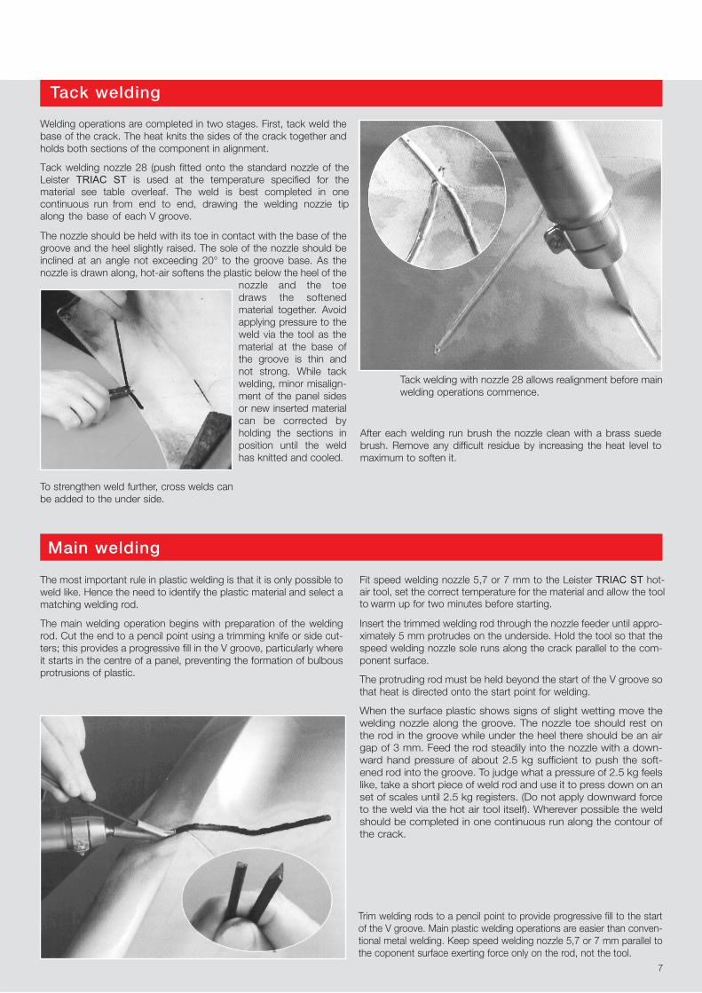
Welding operations are completed in two stages. First, tack weld thebase of the crack. The heat knits the sides of the crack together andholds both sections of the component in alignment.
Tack welding nozzle 28 (push fitted onto the standard nozzle of the Leister TRIAC ST is used at the temperature specified for the material see table overleaf. The weld is best completed in one continuous run from end to end, drawing the welding nozzie tip along the base of each V groove.
The nozzle should be held with its toe in contact with the base of thegroove and the heel slightly raised. The sole of the nozzle should beinclined at an angle not exceeding 20° to the groove base. As thenozzle is drawn along, hot-air softens the plastic below the heel of the
nozzle and the toedraws the softenedmaterial together. Avoidapplying pressure to theweld via the tool as thematerial at the base ofthe groove is thin andnot strong. While tackwelding, minor misalign-ment of the panel sidesor new inserted materialcan be corrected by holding the sections inposition until the weldhas knitted and cooled.
After each welding run brush the nozzle clean with a brass suedebrush. Remove any difficult residue by increasing the heat level tomaximum to soften it.
To strengthen weld further, cross welds canbe added to the under side.
The most important rule in plastic welding is that it is only possible toweld like. Hence the need to identify the plastic material and select amatching welding rod.
The main welding operation begins with preparation of the weldingrod. Cut the end to a pencil point using a trimming knife or side cut-ters; this provides a progressive fill in the V groove, particularly whereit starts in the centre of a panel, preventing the formation of bulbousprotrusions of plastic.
Fit speed welding nozzle 5,7 or 7 mm to the Leister TRIAC ST hot-air tool, set the correct temperature for the material and allow the tool to warm up for two minutes before starting.
Insert the trimmed welding rod through the nozzle feeder until appro-ximately 5 mm protrudes on the underside. Hold the tool so that thespeed welding nozzle sole runs along the crack parallel to the com-ponent surface.
The protruding rod must be held beyond the start of the V groove sothat heat is directed onto the start point for welding.
When the surface plastic shows signs of slight wetting move thewelding nozzle along the groove. The nozzle toe should rest onthe rod in the groove while under the heel there should be an airgap of 3 mm. Feed the rod steadily into the nozzle with a down-ward hand pressure of about 2.5 kg sufficient to push the soft-ened rod into the groove. To judge what a pressure of 2.5 kg feelslike, take a short piece of weld rod and use it to press down on anset of scales until 2.5 kg registers. (Do not apply downward forceto the weld via the hot air tool itself). Wherever possible the weldshould be completed in one continuous run along the contour ofthe crack.
7
Trim welding rods to a pencil point to provide progressive fill to the startof the V groove. Main plastic welding operations are easier than conven-tional metal welding. Keep speed welding nozzle 5,7 or 7 mm parallel tothe coponent surface exerting force only on the rod, not the tool.
Tack welding with nozzle 28 allows realignment before mainwelding operations commence.
www.HotAirTools.com
Authorized Sales & Service CenterAssembly Supplies, Co.1250 Pacific Oaks Place #104Escondido, CA 92029E-Mail [email protected] (800)694-1472
106.996
106.992
106.993
106.989
106.990
106.991
100.303
8
5.7
3.7
7
5
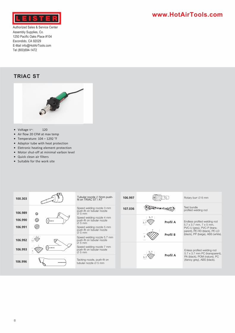
TRIAC ST
• Voltage V~: 120• Air flow 20 CFM at max temp• Temperature: 104 – 1292 °F• Adaptor tube with heat protection• Eletronic heating element protection• Motor shut-off at minimal varbon level• Quick clean air filters• Suitable for the work site
Tubular nozzle ∅ 5mm push-fit on TRIAC ST / AT
Speed welding nozzle 3 mmpush-fit on tubular nozzle ∅ 5 mmSpeed welding nozzle 4 mmpush-fit on tubular nozzle ∅ 5 mmSpeed welding nozzle 5 mmpush-fit on tubular nozzle ∅ 5 mm
Speed welding nozzle 5.7 mm push-fit on tubular nozzle ∅ 5 mmSpeed welding nozzle 7 mm push-fit on tubular nozzle ∅ 5 mm
Tacking nozzle, push-fit ontubular nozzle ∅ 5 mm
107.036
106.997
Test bundle profiled welding rod
5.7
3.7 Profil A
7
5Profil B
5.7
3.7Profil A
Endless profiled welding rod5.7 x 3.7 mm, 7 x 5 mm, PVC-U (grey), PVC-P (trans-parent), PE-HD (black), PE-LD(black), PP (beige), ABS (white).
Enless profiled welding rod 5.7 x 3.7 mm PC (transparent),PA (black), POM (nature), PC(Xenoy grey), ABS (black).
Rotary burr ∅ 6 mm