Plastic Version - Build and share your RC Heli Fleet ... the M3x25 Socket Head Bolt and M3 Nylon Nut...
19
Plastic Version
Transcript of Plastic Version - Build and share your RC Heli Fleet ... the M3x25 Socket Head Bolt and M3 Nylon Nut...

Plastic Version

2
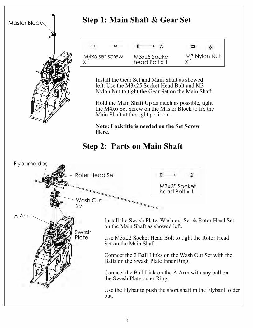
M4x6 set screwx 1
M3 Nylon Nutx 1
Master Block
Here.
Step 1: Main Shaft & Gear Set
Install the Gear Set and Main Shaft as showedleft. Use the M3x25 Socket Head Bolt and M3 Nylon Nut to tight the Gear Set on the Main Shaft.
Hold the Main Shaft Up as much as possible, tightthe M4x6 Set Screw on the Master Block to fix theMain Shaft at the right position.
Note: Locktitle is needed on the Set Screw
Step 2: Parts on Main Shaft
M3x25 Sockethead Bolt x 1
M3x25 Sockethead Bolt x 1
A Arm
Plate
Roter Head Set
Use the Flybar to push the short shaft in the Flybar Holder
SetWash Out
out.
Install the Swash Plate, Wash out Set & Rotor Head Set on the Main Shaft as showed left.
Use M3x22 Socket Head Bolt to tight the Rotor Head Set on the Main Shaft.
Connect the 2 Ball Links on the Wash Out Set with the Balls on the Swash Plate Inner Ring.
Connect the Ball Link on the A Arm with any ball on the Swash Plate outer Ring.
Swash
Flybarholder
3

x 4
A C
Step 3. Landing Gear
3mm Washer
a) Use M3x20 Socket Head Bolts, M3 Nylon Nuts and 4mm Washer to fix
the plastic skid foot on the body. refer to detail view A.
b) Insert the two alumine Skid Tube into the hole of the Skid Foot.
c) Use M3x5 set screws to tight the Skid Tube on the Skid Foot.
refer to detail view C.
M3x16 Sockethead Bolt x 4
M3 Nylon Nutx 4
M3x5 Set Screw
M3x5 set screwx 4
A
Skid Foot
Skid Tube
C
3mm Washer
M3x20
M3 NylonNut
4

M3x10 SetScrew x 2
M4x3 Set Screw x 2
set screw
M3x10 set
screw
screw
M3x3
A
Pallele
M4x3 set
Flybar Stopper
B
AB
Flybar ControlArm
a): Screw the two Paddles in opposite direction onto the Flybar untile the Flybar can be seen from the small hole on the Paddle.
Step 4. Paddles
M3x3 Set Screw x 4
Note: the longer the Flybar Weight away from the center, the more
Dire
cto
n
Screw
ing
Stable the heli is.
dire
ction.
Scre
win
g
Flybar appares here.
Finally fix the set screw in the paddle.
Do not hold here.
Note: Don't hold flybar control arm as a wrench when you fix
Flybar appares here
the paddle onto the flybar.
b): Make sure the two Paddles are balanced to the center and fix the Flybar Stopper. Make sure Two Paddles and two Flybar Control Arm are in the same Panel and fix the Flybar Control Arm. Make sure the Flybar Weight are balance and fix the Flybar Weight.
Note: Locktitle isneeded in all set screws.
5

M3x20 Self TappingBolt x 6
M3x20Self Tapping
Mount
Bolt
Front Servo Mount on the body.
Front Servo
a) Use M3x20 Self Tapping bolts to fix the
M3x10 Self TappingBolt x 4
TrayServo
M3x10Self TappingBolt
b) Use M3x10 Self Tapping bolt to fix the Servo Tray on the Front Servo Mount.
Step 5. Front Servo Mount
6

Engine Set
M3x12 Socket
Engine Set
Washer from
Head Bolt
Engine Mount
Engine.
Clutch
Nut from
a). Assembly Cluth, Fly Wheel, Fan, Engine Mountand the
Fly Wheel
M3x16 Socket
Head Bolt
Compass Engine Tool is need to tightthe enine on the Fly Wheel.
Step 6. Install the Engine
Carburater
c). Finally install the Carburater on the engine, refer to engine manual.
wrenchHex
05-9001 EngineTool
Note: LOCKTITL SHOULD BE USED IN ALL SOCKET HEAD BOLTS HERE.
M3 Washer x 4
M3x16 SocketHead Bolt
M3 washer
b). Insert the whole engine set and fix it on the body with M3 x 16 Socket Head Bolt and washers.
M3x12 Sockethead Bolt x 2
M3x16 Sockethead Bolt x 8
7

view on left).
Turn the Belt 90° clockwisely. (refer to the detailed
a
4
Step 7. Tail
.
GyroRemove the Mount
Insert the Tail Boomand Gear Box
Gyro Mount
b
c
cd
d
e
b
Belt
Wheel
Gyro Mount
Boom
afterwards. Install the Belt around the Pulley Wheel. reinstall the
Pulley
Inside the Frame
M3 Nylon Nutx 2
Head Bolt
Tail Link Supporter
Rudder Servo MountBelt
Boom
Gear Box Set
.
Insert the Tail Boom into the Gear Box Set until Belt go through the whole Boom. Install the Tail Link Supporters and Rudder Servo Mount on the
M3x12 Socket
M3 Nylon Nut
M3x12 Sockethead Bolt x 2
8

Tail Fin
Boom Supporter
Head Bolts x2M3x16 Socket
Head Bolts x2M3x30 Socket
Head Bolts x2M3x40 Socket
Nut x8M3 Nylon
FinVertical
M3 Washer
Nuts
Head BoltM3x16 Socket
M3 Nylon
C
M3x15 SocketHead Bolts x2
M3 Washer
M3 Nylon Nut
Head Bolt
M3 Nylon Nut
M3x15 Socket
Head Bolt
M3 Washer
M3x30 Socket
Head BoltM3x40 Socket
Fin Collars
A&B
on the heli body.
A: Tight up the belt, use M3x30 Socket Head bolt and M3 Nylon Nuts to fix the vertical fin and Tail Gear Box on the boom.
B: Use M3x40 Sockety Head Bolts, washer and M3 Nylon Nuts fix the Horizontal fin and the boom Supporters on the boom. Use M3x15 Socket Head bolt andM3 Nylon Nut to fix the Tail blade on the Blade holder.
C): Use M3 Socket Head Bolt and M3 Nylon Nut to tight the Boom Supporter
Step 8. Fins and Boom Supporters
M3 Washerx6
9
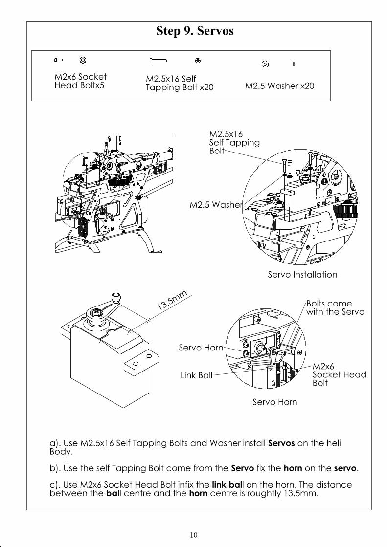
Servo Installation
Bolt
M2.5x16 Self Tapping
M2.5 Washer
Socket Head
with the Servo
Servo Horn
Bolt
Servo Horn
M2x6
Bolts come
Link Ball
13.5mm
Tapping Bolt x20
M2x6 SocketHead Boltx5
M2.5x16 Self
a). Use M2.5x16 Self Tapping Bolts and Washer install Servos on the heliBody.
b). Use the self Tapping Bolt come from the Servo fix the horn on the servo.
c). Use M2x6 Socket Head Bolt infix the link ball on the horn. The distance between the ball centre and the horn centre is roughtly 13.5mm.
Step 9. Servos
M2.5 Washer x20
10

Gyro
Pitch
Cushion
Throttle
RundderWith Sponge
Aileron
Elevator
Receiver
Battery WithSponge Cushion
Boom
Radious StayMain Grip
Wash Out ArmPa
ralle
l to
th
e B
oo
m
Step 11. Radious Stay Arm
servo to radio manual.
goes where refer
a). Adhere Gyro on the Gyro Mount, detail refer to Gyro's manual.
b). Use Nylon Bandage to tie Battery with Sponge Cushion on the front nose.
c). Use Elstic tie Receiver with Sponge Cusion on the front servo mount.
d). Connect servos, gyro, battery with Receiver, which
Radious Stay Arm need to be at an angel so that Main Grips and Washer Out Arms are parallel to the Boom.
Step 10. Wire Up
11

Step 12. Radio Setting Data
after installing Servo, Gyro and other eletronics. Set up your radio with following data.
Pitch Curve
Throttle Curve
Pitch Setting Swash Type Setting
Hovering ID1 ID2 ID3 Autorotation JR FutabaLoop Roll 3D Swash Type SWH
High Pitch 9~10 9~10 7 10 12 S3 120º SR2Hovering 5~5.5 3 0 0 N/A Aile Elev. PitchLow Pitch -4 -6 -7 -10 -7 70% 70% 55%
Above data just give some general idea of setting. It varies by engine,blades,muffler and pilot's style.Adjust by actual flight.
Hovering
0%
25%
50%
75%
100%
1 2 3 4 5
Roll
0%
25%
50%
75%
100%
1 2 3 4 5
3D
0%
25%
50%
75%
100%
1 2 3 4 5
Autorotation
0%
25%
50%
75%
100%
1 2 3 4 5
Loop
0%
25%
50%
75%
100%
1 2 3 4 5
Hovering
0%
25%
50%
75%
100%
1 2 3 4 5
Loop
0%
25%
50%
75%
100%
1 2 3 4 5
Roll
0%
25%
50%
75%
100%
1 2 3 4 5
3D
0%
25%
50%
75%
100%
1 2 3 4 5
Autorotation
0%
25%
50%
75%
100%
1 2 3 4 5
12

90°
Parallel
Main Shaft
Compass Swash Plate Tool 06-0501
Swash Plate
Horizontal
Outer ARm
Inner Arm
c) next adjust the two side L arm links to swash plate to level swash plate. a compass tool can be used here to level swash plate.
to the right angle. Use sub trim in radio program to adjust each servo to get control horn
a) Turn on the radio and set throttle position to mid stick (middle position) For 0 deg. All three servo control horns must 90 deg to the sero edge.
b) next is to adjust links from servo to L arms (2 on outside of frame and 1 in the middle of the frame) so that the L arms are all Horizontal.
Step 13. Set Up
13

90°
90°
3°
90°
90°
Washout control arm
Swash Plate
Main Shaft
d) set the wash out control arm 90 deg to the main shaft.
e). Set the mixing arm 3 deg. downwards to flybar so that the pitch link is 90 deg to the mixing arm.
g). Install and adjust the engine link so that link is 90 deg to the sero horn and the engine horn.
Fly Bar
Grips. One ball link might need to be cut shorter to set the pithc to 0. f). Install main blades and set to 0 deg pitch with the links on main blade
Mixing ARm
14

Linkage Length
Summary
a). Servo Horns level
b) Level L Arms
c) Level Swash Plate
d) Level Wash out Arm
Linkage Length
3 deg. downwards
f) Set 0 Pitch
e) Mixing ARmf)Link to cut in
:
All linkage length are measured in this way. In case you change ball links, you
can set the same measurement.
15

27mm (1.06inch)
68mm (2.67inch)49mm (1.93inch)
57mm (2.24inch)67mm (2.63inch)
99mm (3.9inch)
Linkage Lenght 79mm(3.11inch) x 1: engine control
Linkage Length 27mm (1.06 inch) x 2: main blade holder to mix arm
Linkage Length 49mm (1.93 inch) x 2: fly bar control arm to wash out control arm
Linkage Lenght 68mm (2.67inch) x 2: mixing arm to swash plate inner ring
Linkage Lenght 57mm (2.24inch) x 2: swash plate outer ring to L arm
Linkage Lenght 99mm(3.90inch) x 2: L arm to Horns of outer servos
Linkage Lenght 67mm(2.63inch) x 1: front arm to horn of inner servo.
79mm (3.11inch)
16

M3x15 Set Screw x 4
Canopy Mount
M3x15 Set Screw
Step 14 Canopy Mount
box.
Use M3x15 Set Screws to install the 4 canopy mount on the heli body so that
: The Bolts connecting the Main Grips to Spindle are normally Not
Locktitled when out of box. Regular checks are needed to ensure the safety of flights.
later the Canopy can be installed.
Reminder
Bolt here is not Locktitled when out
Bolt here is not Locktitled when out box.
17
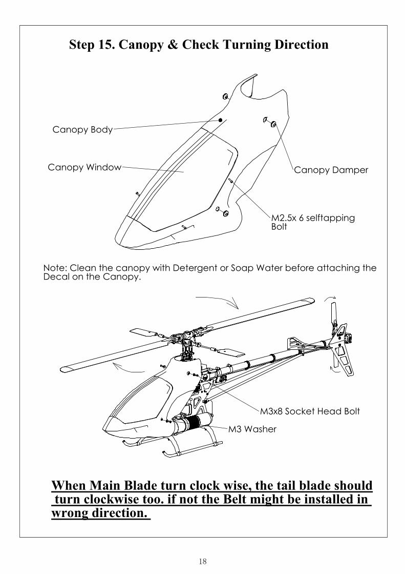
Canopy DamperCanopy Window
BoltM2.5x 6 selftapping
Canopy Body
Step 15. Canopy & Check Turning Direction
M3 Washer
wrong direction. turn clockwise too. if not the Belt might be installed in
M3x8 Socket Head Bolt
When Main Blade turn clock wise, the tail blade should
Note: Clean the canopy with Detergent or Soap Water before attaching theDecal on the Canopy.
18

( )1
( )2
( )3
( )4
( )4
( )6
( )6
( )5
( )5
( )5
( )8
( )8
( )7
( )7
( )9
( )9 ( )10
( )10
( )11
( )11
( )12
( )12
( )13
( )13
( )14
( )14
( )15
( )15
( )1
( )2
( )3
19