Plarailchain SP - PISCO
14
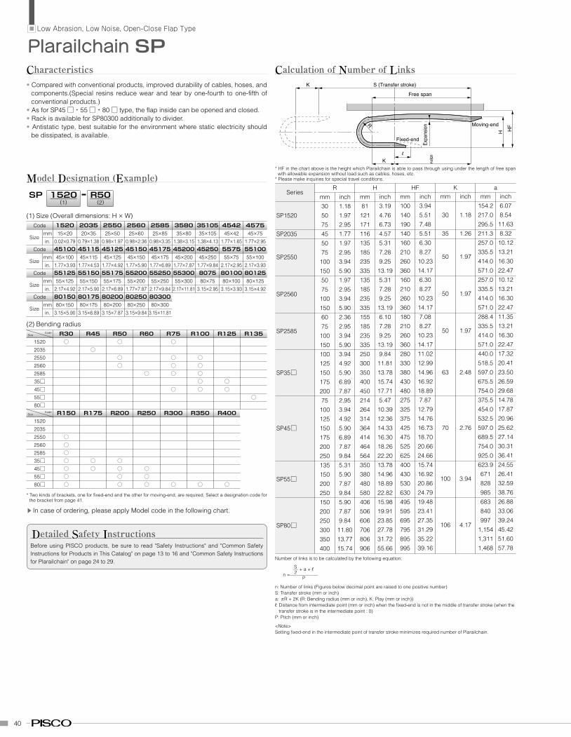
40 Fixed-end Moving-end K l R S - 2 Free span S (Transfer stroke) K H HF Expansion Plarailchain SP • Compared with conventional products, improved durability of cables, hoses, and components.(Special resins reduce wear and tear by one-fourth to one-fifth of conventional products.) • As for SP45 □・55 □・80 □ type, the flap inside can be opened and closed. • Rack is available for SP80300 additionally to divider. • Antistatic type, best suitable for the environment where static electricity should be dissipated, is available. C haracteristics Low Abrasion, Low Noise, Open-Close Flap Type SP M odel D esignation ( E xample) R50 (2) (1) Size (Overall dimensions: H × W) 1520 (1) Code 1520 2035 2550 2560 2585 3580 35105 4542 4575 Size mm 15×20 20×35 25×50 25×60 25×85 35×80 35×105 45×42 45×75 in. 0.02×0.79 0.79×1.38 0.98×1.97 0.98×2.36 0.98×3.35 1.38×3.15 1.38×4.13 1.77×1.65 1.77×2.95 (2) Bending radius Size Code R30 R45 R50 R60 R75 R100 R125 R135 1520 ○ ○ ○ 2035 ○ 2550 ○ ○ ○ 2560 ○ ○ ○ 2585 ○ ○ ○ 35□ ○ ○ 45□ ○ ○ ○ 55□ ○ 80□ * Two kinds of brackets, one for fixed-end and the other for moving-end, are required. Select a designation code for the bracket from page 41. ▲ In case of ordering, please apply Model code in the following chart. Before using PISCO products, be sure to read "Safety Instructions" and "Common Safety Instructions for Products in This Catalog" on page 13 to 16 and "Common Safety Instructions for Plarailchain" on page 24 to 29. D etailed S afety I nstructions Code 45100 45115 45125 45150 45175 45200 45250 5575 55100 Size mm 45×100 45×115 45×125 45×150 45×175 45×200 45×250 55×75 55×100 in. 1.77×3.93 1.77×4.53 1.77×4.92 1.77×5.90 1.77×6.89 1.77×7.87 1.77×9.84 2.17×2.95 2.17×3.93 Code 55125 55150 55175 55200 55250 55300 8075 80100 80125 Size mm 55×125 55×150 55×175 55×200 55×250 55×300 80×75 80×100 80×125 in. 2.17×4.92 2.17×5.90 2.17×6.89 1.77×7.87 2.17×9.84 2.17×11.81 3.15×2.95 3.15×3.93 3.15×4.92 Code 80150 80175 80200 80250 80300 Size mm 80×150 80×175 80×200 80×250 80×300 in. 3.15×5.90 3.15×6.89 3.15×7.87 3.15×9.84 3.15×11.81 Size Code R150 R175 R200 R250 R300 R350 R400 1520 2035 2550 ○ 2560 ○ 2585 ○ 35□ ○ ○ ○ 45□ ○ ○ ○ ○ 55□ ○ ○ ○ 80□ ○ ○ ○ ○ ○ ○ C alculation of N umber of L inks Series SP1520 SP2035 SP2550 SP2560 SP2585 SP35□ SP45□ SP55□ SP80□ R Number of links is to be calculated by the following equation: n =— P n: Number of links (Figures below decimal point are raised to one positive number) S: Transfer stroke (mm or inch) a: πR + 2K (R: Bending radius (mm or inch), K: Play (mm or inch)) l: Distance from intermediate point (mm or inch) when the fixed-end is not in the middle of transfer stroke (when the transfer stroke is in the intermediate point : 0) P: Pitch (mm or inch) <Note> Setting fixed-end in the intermediate point of transfer stroke minimizes required number of Plarailchain. * HF in the chart above is the height which Plarailchain is able to pass through using under the length of free span with allowable expansion without load such as cables, hoses, etc. * Please make inquiries for special travel conditions. H HF K a mm 30 50 75 45 50 75 100 150 50 75 100 150 60 75 100 150 100 125 150 175 200 75 100 125 150 175 200 250 135 150 200 250 150 200 250 300 350 400 inch 1.18 1.97 2.95 1.77 1.97 2.95 3.94 5.90 1.97 2.95 3.94 5.90 2.36 2.95 3.94 5.90 3.94 4.92 5.90 6.89 7.87 2.95 3.94 4.92 5.90 6.89 7.87 9.84 5.31 5.90 7.87 9.84 5.90 7.87 9.84 11.80 13.77 15.74 mm 81 121 171 116 135 185 235 335 135 185 235 335 155 185 235 335 250 300 350 400 450 214 264 314 364 414 464 564 350 380 480 580 406 506 606 706 806 906 inch 3.19 4.76 6.73 4.57 5.31 7.28 9.25 13.19 5.31 7.28 9.25 13.19 6.10 7.28 9.25 13.19 9.84 11.81 13.78 15.74 17.71 5.47 10.39 12.36 14.33 16.30 18.26 22.20 13.78 14.96 18.89 22.82 15.98 19.91 23.85 27.78 31.72 55.66 mm 100 140 190 140 160 210 260 360 160 210 260 360 180 210 260 360 280 330 380 430 480 275 325 375 425 475 525 625 400 430 530 630 495 595 695 795 895 995 inch 3.94 5.51 7.48 5.51 6.30 8.27 10.23 14.17 6.30 8.27 10.23 14.17 7.08 8.27 10.23 14.17 11.02 12.99 14.96 16.92 18.89 7.87 12.79 14.76 16.73 18.70 20.66 24.66 15.74 16.92 20.86 24.79 19.48 23.41 27.35 31.29 35.22 39.16 mm 30 35 50 50 50 63 70 100 106 inch 1.18 1.26 1.97 1.97 1.97 2.48 2.76 3.94 4.17 mm 154.2 217.0 295.5 211.3 257.0 335.5 414.0 571.0 257.0 335.5 414.0 571.0 288.4 335.5 414.0 571.0 440.0 518.5 597.0 675.5 754.0 375.5 454.0 532.5 597.0 689.5 754.0 925.0 623.9 671 828 985 683 840 997 1,154 1,311 1,468 inch 6.07 8.54 11.63 8.32 10.12 13.21 16.30 22.47 10.12 13.21 16.30 22.47 11.35 13.21 16.30 22.47 17.32 20.41 23.50 26.59 29.68 14.78 17.87 20.96 25.62 27.14 30.31 36.41 24.55 26.41 32.59 38.76 26.88 33.06 39.24 45.42 51.60 57.78 S — + a + l 2
Transcript of Plarailchain SP - PISCO
40
Fixed-end
Moving-end
Kl
R
S-2
Free span
S (Transfer stroke)K
H HF
Expa
nsion
Plarailchain SP
• Compared with conventional products, improved durability of cables, hoses, and components.(Special resins reduce wear and tear by one-fourth to one-fifth of conventional products.)
• As for SP45□・55□・80□ type, the flap inside can be opened and closed.• Rack is available for SP80300 additionally to divider.• Antistatic type, best suitable for the environment where static electricity should
be dissipated, is available.
Characteristics
Low Abrasion, Low Noise, Open-Close Flap Type
SP
Model Designation (Example)R50
(2)
(1) Size (Overall dimensions: H × W)
1520(1)
Code 1520 2035 2550 2560 2585 3580 35105 4542 4575
Size mm 15×20 20×35 25×50 25×60 25×85 35×80 35×105 45×42 45×75
in. 0.02×0.79 0.79×1.38 0.98×1.97 0.98×2.36 0.98×3.35 1.38×3.15 1.38×4.13 1.77×1.65 1.77×2.95
(2) Bending radius Size
Code R30 R45 R50 R60 R75 R100 R125 R135 1520 ○ ○ ○ 2035 ○ 2550 ○ ○ ○ 2560 ○ ○ ○ 2585 ○ ○ ○ 35□ ○ ○ 45□ ○ ○ ○ 55□ ○ 80□
* Two kinds of brackets, one for fixed-end and the other for moving-end, are required. Select a designation code for the bracket from page 41.
▲
In case of ordering, please apply Model code in the following chart.
Before using PISCO products, be sure to read "Safety Instructions" and "Common Safety Instructions for Products in This Catalog" on page 13 to 16 and "Common Safety Instructions for Plarailchain" on page 24 to 29.
Detailed Safety Instructions
Code 45100 451154512545150451754520045250 5575 55100
Size mm 45×100 45×115 45×125 45×150 45×175 45×200 45×250 55×75 55×100
in. 1.77×3.93 1.77×4.53 1.77×4.92 1.77×5.90 1.77×6.89 1.77×7.87 1.77×9.84 2.17×2.95 2.17×3.93
Code 55125 5515055175552005525055300 8075 8010080125
Size mm 55×125 55×150 55×175 55×200 55×250 55×300 80×75 80×100 80×125
in. 2.17×4.92 2.17×5.90 2.17×6.89 1.77×7.87 2.17×9.84 2.17×11.81 3.15×2.95 3.15×3.93 3.15×4.92
Code 80150 80175802008025080300
Size mm 80×150 80×175 80×200 80×250 80×300
in. 3.15×5.90 3.15×6.89 3.15×7.87 3.15×9.84 3.15×11.81
Size Code R150 R175 R200 R250 R300 R350 R400
1520
2035
2550 ○ 2560 ○ 2585 ○ 35□ ○ ○ ○ 45□ ○ ○ ○ ○ 55□ ○ ○ ○ 80□ ○ ○ ○ ○ ○ ○
Calculation of Number of Links
Series
SP1520
SP2035
SP2550
SP2560
SP2585
SP35□
SP45□
SP55□
SP80□
R
Number of links is to be calculated by the following equation:
n =—P
n: Number of links (Figures below decimal point are raised to one positive number)S: Transfer stroke (mm or inch)a: πR + 2K (R: Bending radius (mm or inch), K: Play (mm or inch))l: Distance from intermediate point (mm or inch) when the fixed-end is not in the middle of transfer stroke (when the
transfer stroke is in the intermediate point : 0)P: Pitch (mm or inch)
<Note>Setting fixed-end in the intermediate point of transfer stroke minimizes required number of Plarailchain.
* HF in the chart above is the height which Plarailchain is able to pass through using under the length of free span with allowable expansion without load such as cables, hoses, etc.
* Please make inquiries for special travel conditions.
H HF K amm305075455075
1001505075
1001506075
10015010012515017520075
100125150175200250135150200250150200250300350400
inch1.181.972.951.771.972.953.945.901.972.953.945.902.362.953.945.903.944.925.906.897.872.953.944.925.906.897.879.845.315.907.879.845.907.879.84
11.8013.7715.74
mm81
121171116135185235335135185235335155185235335250300350400450214264314364414464564350380480580406506606706806906
inch3.194.766.734.575.317.289.25
13.195.317.289.25
13.196.107.289.25
13.199.84
11.8113.7815.7417.715.47
10.3912.3614.3316.3018.2622.2013.7814.9618.8922.8215.9819.9123.8527.7831.7255.66
mm100140190140160210260360160210260360180210260360280330380430480275325375425475525625400430530630495595695795895995
inch3.945.517.485.516.308.27
10.2314.176.308.27
10.2314.177.088.27
10.2314.1711.0212.9914.9616.9218.897.87
12.7914.7616.7318.7020.6624.6615.7416.9220.8624.7919.4823.4127.3531.2935.2239.16
mm
30
35
50
50
50
63
70
100
106
inch
1.18
1.26
1.97
1.97
1.97
2.48
2.76
3.94
4.17
mm154.2217.0295.5211.3257.0335.5414.0571.0257.0335.5414.0571.0288.4335.5414.0571.0440.0518.5597.0675.5754.0375.5454.0532.5597.0689.5754.0925.0623.9671828985683840997
1,1541,3111,468
inch6.078.54
11.638.32
10.1213.2116.3022.4710.1213.2116.3022.4711.3513.2116.3022.4717.3220.4123.5026.5929.6814.7817.8720.9625.6227.1430.3136.4124.5526.4132.5938.7626.8833.0639.2445.4251.6057.78
S— + a + l2
41
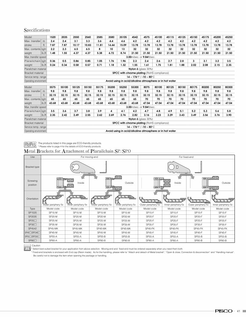
Model 1520 2035 2550 2560 2585 3580 35105 4542 4575 45100 45115 45125 45150 45175 45200 45250Max. transfer stroke
m 2.4 2.4 3.1 3.3 3.6 4.4 4.6 4.2 4.2 4.2 4.2 4.2 4.2 4.2 4.2 4.2ft 7.87 7.87 10.17 10.83 11.81 14.44 15.09 13.78 13.78 13.78 13.78 13.78 13.78 13.78 13.78 13.78
Max. contents weight
kg/m 2.2 2.3 6.5 6.5 8 10 13 32 32 32 32 32 32 32 32 32lb./ft 1.48 1.55 4.37 4.37 5.38 6.72 8.74 21.50 21.50 21.50 21.50 21.50 21.50 21.50 21.50 21.50
Max. transfer speed 3.00m/sec. or 9.84ft/sec.Plarailchain weight
kg/m 0.36 0.5 0.86 0.85 1.05 1.76 1.96 2.3 2.4 2.6 2.7 2.8 3 3.1 3.2 3.5lb./ft 0.24 0.34 0.58 0.57 0.71 1.18 1.32 1.55 1.61 1.75 1.81 1.88 2.02 2.08 2.15 2.35
Plarailchain material Nylon 6 (glass 30%)Bracket material SPCC with chrome plating (RoHS compliance)Service temp. range 14 ~ 176°F / -10 ~ 80°COperating environment Avoid using in acid/alkaline atmosphere or in hot water
Specifications
Model 5575 55100 55125 55150 55175 55200 55250 55300 8075 80100 80125 80150 80175 80200 80250 80300Max. transfer stroke
m 9.8 9.8 9.8 9.8 9.8 9.8 9.8 9.8 9.8 9.8 9.8 9.8 9.8 9.8 9.8 9.8ft 32.15 32.15 32.15 32.15 32.15 32.15 32.15 32.15 32.15 32.15 32.15 32.15 32.15 32.15 32.15 32.15
Max. contents weight
kg/m 65 65 65 65 65 65 65 65 70 70 70 70 70 70 70 70lb./ft 43.68 43.68 43.68 43.68 43.68 43.68 43.68 43.68 47.04 47.04 47.04 47.04 47.04 47.04 47.04 47.04
Max. transfer speed 3.00m/sec. or 9.84ft/sec.Plarailchain weight
kg/m 3.5 3.6 3.7 3.8 3.9 4 4.1 4.2 4.7 4.8 4.9 5.1 5.2 5.3 5.6 5.8lb./ft 2.35 2.42 2.49 2.55 2.62 2.69 2.76 2.82 3.16 3.23 3.29 3.43 3.49 3.56 3.76 3.90
Plarailchain material Nylon 6 (glass 30%)Bracket material SPCC with chrome plating (RoHS compliance)Service temp. range 14 ~ 176°F / -10 ~ 80°COperating environment Avoid using in acid/alkaline atmosphere or in hot water
Use
Bracket type
Metal Brackets for Attachment of Plarailchain SP/SPOFor moving-end
Screwing
position
Orientation
Type
SP1520
SP2035
SP25□SP35□SP4542
SP45□/SPO45□SP55□/SPO55□
SP80□
Model code
SP15-M
SP20-M
SP25-M
SP35-M
SP45-MK
SP45-M
SP55-A
SP80-A
Model code
SP15-M
SP20-M
SP25-M
SP35-M
SP45-MK
SP45-M
SP55-B
SP80-B
Model code
SP15-F
SP20-F
SP25-F
SP35-F
SP45-FK
SP45-F
SP55-A
SP80-A
Model code
SP15-F
SP20-F
SP25-F
SP35-F
SP45-FK
SP45-F
SP55-B
SP80-B
Model code
SP15-M
SP20-M
SP25-M
SP35-M
SP45-MK
SP45-M
SP55-A
SP80-A
Model code
SP15-M
SP20-M
SP25-M
SP35-M
SP45-MK
SP45-M
SP55-B
SP80-B
Model code
SP15-F
SP20-F
SP25-F
SP35-F
SP45-FK
SP45-F
SP55-A
SP80-A
Model code
SP15-F
SP20-F
SP25-F
SP35-F
SP45-FK
SP45-F
SP55-B
SP80-B
For fixed-end
Outside OutsideInside Inside
Inner periphery fix Inner periphery fixInner periphery fix Inner periphery fix Outer periphery fixOuter periphery fixOuter periphery fixOuter periphery fix
Caution* Select best-suited bracket for your application from above selection. Moving-end and fixed-end must be ordered separately when you need them both.
* Fixed-end brackets is enclosed with End cap (Resin made). As for the handling, please refer to ''Attach and detach of Metal bracket'', ''Open & close, Connection & disconnection'' and ''Handling manual''.
Be careful not to damage the item when opening the package or handling.
The products listed in this page are ECO-friendly products.* Please refer to page 4 for the details of ECO-friendly products.
42
wW
Tt
øD
Tt
wW
øD
Tt
wW
øD
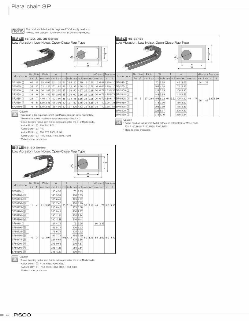
SPLow Abrasion, Low Noise, Open-Close Flap Type
SP1520-
SP2035-
SP2550-
SP2560-
SP2585-
SP3580-
SP35105-
Model code
Caution* Free span is the maximum length that Plarailchain can travel horizontally.
* The metal brackets must be ordered separately. (See P. 41)
* Select bending radius from the list below and enter into of Model code.
As for SP15**- :R30, R50, R75
As for SP20**- :R45
As for SP25**- :R50, R75, R100, R150
As for SP35**- :R100, R125, R150, R175, R200
* Make-to-order production
No. of links
/m
40
32
28
28
23
16
16
/ft.
12
10
9
9
7
5
5
Pitch
mm
25
32
36
36
43.5
62.5
62.5
inch
0.98
1.26
1.42
1.42
1.71
2.46
2.46
W
mm
32
47
65
75
100
101
126
inch
1.26
1.85
2.56
2.95
3.94
3.98
4.96
T
mm
21
26
35
35
35
50
50
inch
0.83
1.02
1.38
1.38
1.38
1.97
1.97
w
mm
20
35
50
60
85
80
105
inch
0.79
1.38
1.97
2.36
3.35
3.15
4.13
t
mm
15
20
25
25
25
35
35
inch
0.59
0.79
0.98
0.98
0.98
1.38
1.38
øD (max.)
mm
12
16
20
20
20
28
28
inch
0.47
0.63
0.79
0.79
0.79
1.10
1.10
Free span
m
1.25
1.25
1.63
1.75
1.88
2.25
2.38
ft.
4.10
4.10
5.35
5.74
6.17
7.38
7.81
15,20,25,35 Series SPLow Abrasion, Low Noise, Open-Close Flap Type
SP4542-
SP4575-
SP45100-
SP45115-
SP45125-
SP45150-
SP45175-
SP45200-
SP45250-
Model codeNo. of links
/m
15
/ft.
5
Pitch
mm
67
inch
2.64
W
mm
70
103
128
143
153
178
203
228
278
inch
2.75
4.05
5.03
5.63
6.02
7.00
7.99
8.97
10.94
T
mm
64
inch
2.52
w
mm
42
75
100
115
125
150
175
200
250
inch
1.65
2.95
3.93
4.53
4.92
5.90
6.89
7.87
9.84
t
mm
45
inch
1.77
øD (max.)
mm
34
36
inch
1.33
1.42
Free span
m
2.13
ft.
6.99
SPLow Abrasion, Low Noise, Open-Close Flap Type
SP5575-
SP55100-
SP55125-
SP55150-
SP55175-
SP55200-
SP55250-
SP55300-
SP8075-
SP80100-
SP80125-
SP80150-
SP80175-
SP80200-
SP80250-
SP80300-
Model codeNo. of links
/m
11
10
/ft.
4
3
Pitch
mm
91
100
inch
3.58
3.94
W
mm
115
140
165
190
215
240
290
340
121
146
171
196
221
246
296
346
inch
4.52
5.51
6.49
7.47
8.46
9.44
11.41
13.38
4.76
5.74
6.73
7.71
8.69
9.68
11.65
13.62
T
mm
80
105
inch
3.15
4.13
w
mm
75
100
125
150
175
200
250
300
75
100
125
150
175
200
250
300
inch
2.95
3.93
4.92
5.90
6.88
7.87
9.84
11.81
2.95
3.93
4.92
5.90
6.88
7.87
9.84
11.81
t
mm
55
80
inch
2.16
3.15
øD (max.)
mm
44
60
64
inch
1.73
2.36
2.52
Free span
m
5.0
5.0
ft.
16.40
16.40
55,80Series
Caution* Select bending radius from the list below and enter into of Model code.
R75, R100, R125, R150, R175, R200, R250
* Make-to-order production
Caution* Select bending radius from the list below and enter into of Model code.
As for SP55**- :R135, R150, R200, R250
As for SP80**- :R150, R200, R250, R300, R350, R400
* Make-to-order production
45 Series
Plarailchain SP
The products listed in this page are ECO-friendly products.* Please refer to page 4 for the details of ECO-friendly products.
43
SB□-SPDivider
SP2035
SP25□SP35□SP45□SP55□SP80□
Attachable
Model code
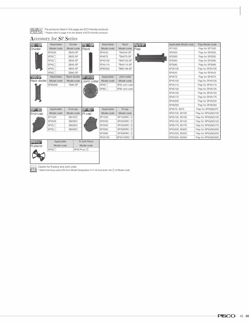
Accessory for SP Series
SB20-SP
SB25-SP
SB35-SP
SB45-SP
SB55-SP
SB80-SP
Divider
Model codeTB□-SPRack
SP4542
SP4575
SP45100
SP45115
SP80300
Attachable
Model code
TB4542-SP
TB4575-SP
TB45100-SP
TB45115-SP
TB80146-SP
Rack
Model code
TS80-SPRack divider
SP80300
Attachable
Model code
TS80-SP
Rack divider
Model code
SP□ECEnd-cap
SP1520
SP2035
SP25□SP35□
Applicable
Model code
SB15EC
SB20EC
SB25EC
SB35EC
End-cap
Model codeSP□RC-□R-cap
SP1520
SP2035
SP2550
SP2585
SP3580
SP35105
Applicable
Model code
SP1520RC-
SP2035RC-
SP2550RC-
SP2585RC-
SP3580RC-
SP35105RC-
R-cap
Model code
SP45R -pc □R-piece
SP45□
Applicable
Model code
SP45 R-pc
R Joint Piece
Model code
SP□ Joint collarJoint collar
SP55□SP80□
Applicable
Model code
SP55 Joint collar
SP80 Joint collar
Joint collar
Model code
FlapforSP□Flap SP1520
SP2035
SP2550
SP2585
SP3580
SP35105
SP4542
SP4575
SP45100
SP45115
SP45125
SP45150
SP45175
SP45200
SP45250
SP5575, 8075
SP55100, 80100
SP55125, 80125
SP55150, 80150
SP55175, 80175
SP55200, 80200
SP55250, 80250
SP55300, 80300
Applicable Model code
Flap for SP1520
Flap for SP2035
Flap for SP2550
Flap for SP2585
Flap for SP3580
Flap for SP35105
Flap for SP4542
Flap for SP4575
Flap for SP45100
Flap for SP45115
Flap for SP45125
Flap for SP45150
Flap for SP45175
Flap for SP45200
Flap for SP45250
Flap for SP55(80)75
Flap for SP55(80)100
Flap for SP55(80)125
Flap for SP55(80)150
Flap for SP55(80)175
Flap for SP55(80)200
Flap for SP55(80)250
Flap for SP55(80)300
Flap Model code
Caution for R-piece and Joint collar* Select bending radius (R) from Model Designation in P. 40 and enter into of Model code.
The products listed in this page are ECO-friendly products.* Please refer to page 4 for the details of ECO-friendly products.
24
SC15□~35□
0 0.25 0.5 0.75 1
12K 2 3 4
1.25 1.5 1.75 2 2.25
1
2
3
4
5
6
7
Transfer stroke (m)
Free span (m)
Wei
ght o
f cab
le/h
ose
(kg/
m)
10
20
30
40
50
60
70
Rea
ctiv
e fo
rce
(N)
①
②
Common Safety Instructions for PlarailchainBefore selecting or using PISCO products, read the following instructions. Read the detailed instructions for individual series as well as the instructions below.
: 1. Never step on Plarailchain. Otherwise the chain may break and you will fall down.2. When connecting, opening, closing, or carrying out maintenance and checks, hold the Plarailchain motionless. Otherwise the Plarailchain may run or fall
under its own weight, thus doing injuries to you.3. Pay attention to the flexing areas of the Plarailchain. You can get injured with your hand caught in the flexing area.4. Before conducting maintenance or checks of Plarailchain, be sure to turn off power supply to the equipment for your safety.5. The Plarailchain should only be used within stated specifications and conditions.6. Never perform disassembly or remodeling that can affect the basic structure, performance or function of the equipment.7. Please tighten it surely so that a fitting does not loosen. There is danger to cause the damage of the whole system when the slack occurs.8. An inertial force, mass load, and reactive force (the force that Plarailchain is going to lug out) are added to the mount of the Plarailchain depending
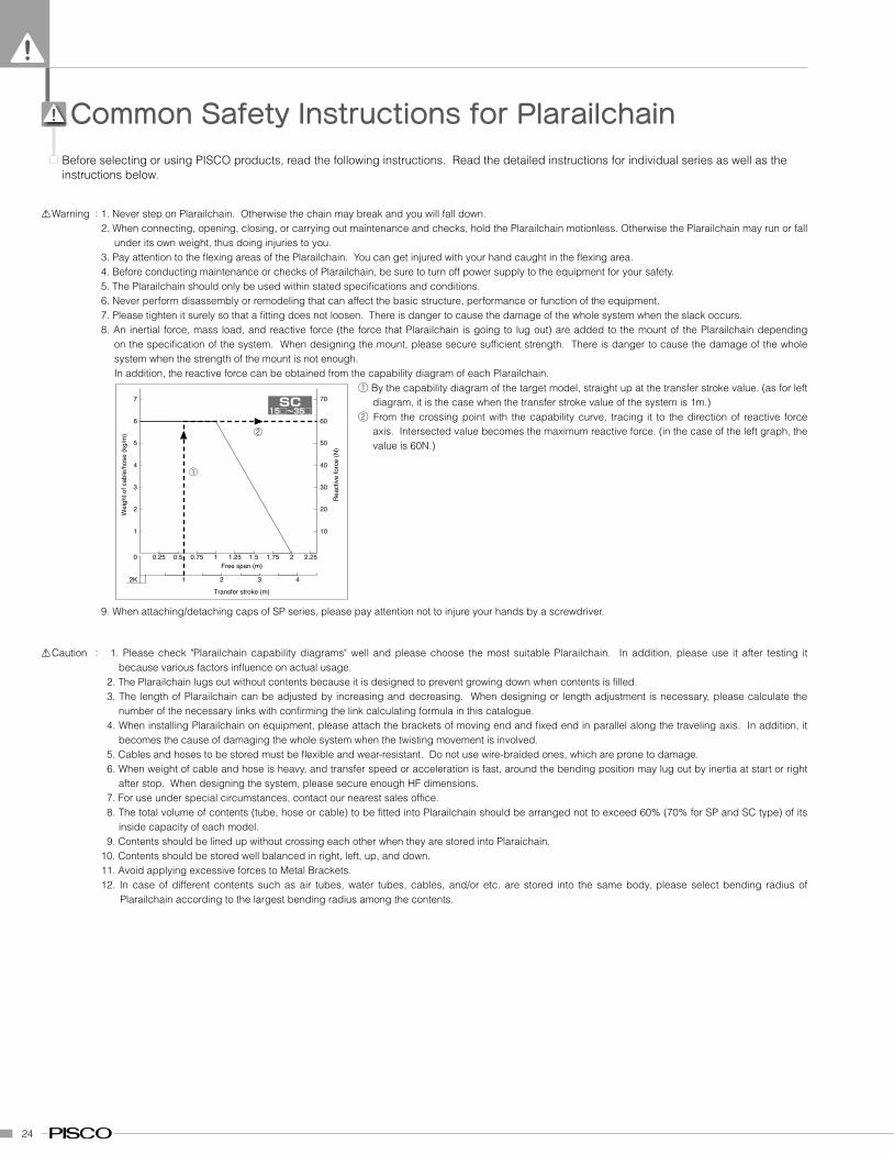
on the specification of the system. When designing the mount, please secure sufficient strength. There is danger to cause the damage of the whole system when the strength of the mount is not enough.In addition, the reactive force can be obtained from the capability diagram of each Plarailchain.
① By the capability diagram of the target model, straight up at the transfer stroke value. (as for left diagram, it is the case when the transfer stroke value of the system is 1m.)
② From the crossing point with the capability curve, tracing it to the direction of reactive force axis. Intersected value becomes the maximum reactive force. (in the case of the left graph, the value is 60N.)
Warning
: 1. Please check "Plarailchain capability diagrams" well and please choose the most suitable Plarailchain. In addition, please use it after testing it because various factors influence on actual usage.
2. The Plarailchain lugs out without contents because it is designed to prevent growing down when contents is filled.3. The length of Plarailchain can be adjusted by increasing and decreasing. When designing or length adjustment is necessary, please calculate the
number of the necessary links with confirming the link calculating formula in this catalogue.4. When installing Plarailchain on equipment, please attach the brackets of moving end and fixed end in parallel along the traveling axis. In addition, it
becomes the cause of damaging the whole system when the twisting movement is involved.5. Cables and hoses to be stored must be flexible and wear-resistant. Do not use wire-braided ones, which are prone to damage.6. When weight of cable and hose is heavy, and transfer speed or acceleration is fast, around the bending position may lug out by inertia at start or right
after stop. When designing the system, please secure enough HF dimensions.7. For use under special circumstances, contact our nearest sales office.8. The total volume of contents (tube, hose or cable) to be fitted into Plarailchain should be arranged not to exceed 60% (70% for SP and SC type) of its
inside capacity of each model.9. Contents should be lined up without crossing each other when they are stored into Plaraichain.
10. Contents should be stored well balanced in right, left, up, and down.11. Avoid applying excessive forces to Metal Brackets.12. In case of different contents such as air tubes, water tubes, cables, and/or etc. are stored into the same body, please select bending radius of
Plarailchain according to the largest bending radius among the contents.
Caution
9. When attaching/detaching caps of SP series, please pay attention not to injure your hands by a screwdriver.
25
0 0.25 0.5 0.75 11 2 3
1.25
306 ø19
408・412 ø22
204・206 ø11102 ø7
202・203 ø11
1.5 1.75 (F)
1
21.51.2
3
4
5
6
7
8
9
10
Transfer stroke (m)
Wei
ght o
f cab
le/h
ose
(kg/
m)
10
20
30
40
50
60
70
80
90
100
Rea
ctiv
e fo
rce
(N)
Rea
ctiv
e fo
rce
(N)
2K
HPU
0
2
0.5 1 1.5 22 4 6
2.5
615 ø36
3 3.5 (F)
468
1012141618202224262830
20406080100120140160180200220240260280300
Transfer stroke (m)
Wei
ght o
f cab
le/h
ose
(kg/
m)
2K
HPU615
0 0.25 0.5 0.75 11 2 3
1.25
408・412 ø20
204・206 ø11202・203 ø10
1.5 1.75 (F)
1
22.5
3
4
5
6
7
8
9
10
10
20
30
40
50
60
70
80
90
100
Transfer stroke (m)
Wei
ght o
f cab
le/h
ose
(kg/
m)
Wei
ght o
f cab
le/h
ose
(kg/
m)
Rea
ctiv
e fo
rce
(N)
Rea
ctiv
e fo
rce
(N)
2K
HPO
0
2
0.5 1 1.5 22 4 6 8 91 3 5 7
2.5
819 ø46
512 ø36
3 3.5 4 4.5 (F)
141210
864
16182022242628303234363840
20
140120100806040
160180200220240260280300320340360380400
Transfer stroke (m)2K
HPO512・819
0 0.25 0.5 0.75 11 2 3
1.25
408・412 ø20
1.5 1.75 (F)
1
22.5
3
4
5
6
7
8
9
10
10
20
30
40
50
60
70
80
90
100
Transfer stroke (m)
Wei
ght o
f cab
le/h
ose
(kg/
m)
Rea
ctiv
e fo
rce
(N)
2K
HPE
0 0.25 0.5 0.75 11 2 3
1.25
206 ø12204 ø12
202・203 ø12
101 ø7
1.5 1.75 (F)
1
21.5
3
4
5
6
7
8
9
10
10
20
30
40
50
60
70
80
90
100
Transfer stroke (m)W
eigh
t of c
able
/hos
e (k
g/m
)
Rea
ctiv
e fo
rce
(N)
2K
HPK
0 0.25 0.5 0.75 11 2 3
1.25
HPM 206 ø13
HPM 204・205 ø14
1.5 1.75 (F)
1
2
3
4
5
6
7
8
9
10
10
20
30
40
50
60
70
80
90
100
Transfer stroke (m)
Wei
ght o
f cab
le/h
ose
(kg/
m)
Rea
ctiv
e fo
rce
(N)
2K
HPM
0 0.25 0.5 0.75 11 2 3
1.25
306 ø30
204 ø23 HPC 50
HPC 100
HPC 200203 ø19
1.5 1.75 (F)
1
2
3
4
5
6
7
8
9
10
10
20
30
40
50
60
70
80
90
100
Transfer stroke (m)
Wei
ght o
f cab
le/h
ose
(kg/
m)
Rea
ctiv
e fo
rce
(N)
2K
HPC
0 0.5 1 1.5 2
12K 2 3 4 5 6 7 8 9 10
2.5 3 3.5 4 4.5 5
51015202530354045505560657075
50100150200250300350400450500550600650700750
Transfer stroke (m)
Free span (m)
Wei
ght o
f cab
le/h
ose
(kg/
m)
Rea
ctiv
e fo
rce
(N)
SP45□、55□、80□
45□ø36
55□ø44
80□ø64SP
15□~35□
0 0.25 0.5 0.75 1
12K 2 3 4 5
1.25 1.5 1.75 2 2.25 2.5
123456789
1011121314
102030405060708090100110120130140
Transfer stroke (m)
Free span (m)
Wei
ght o
f cab
le/h
ose
(kg/
m)
Rea
ctiv
e fo
rce
(N)
2585 ø20
3580 ø28
35105 ø28
2550 ø20
2560 ø20
1520 ø122035 ø16
SC15□~35□
0 0.25 0.5 0.75 1
12K 2 3 4
1.25 1.5 1.75 2
1
2
3
4
5
6
7
10
20
30
40
50
60
70
Transfer stroke (m)
Free span (m)
Wei
ght o
f cab
le/h
ose
(kg/
m)
Rea
ctiv
e fo
rce
(N)
L3050 ø24
3560 ø2835100 ø28
2540・2560・L2570・2580 ø20
1520 ø12
L2020・2040・L2050 ø16
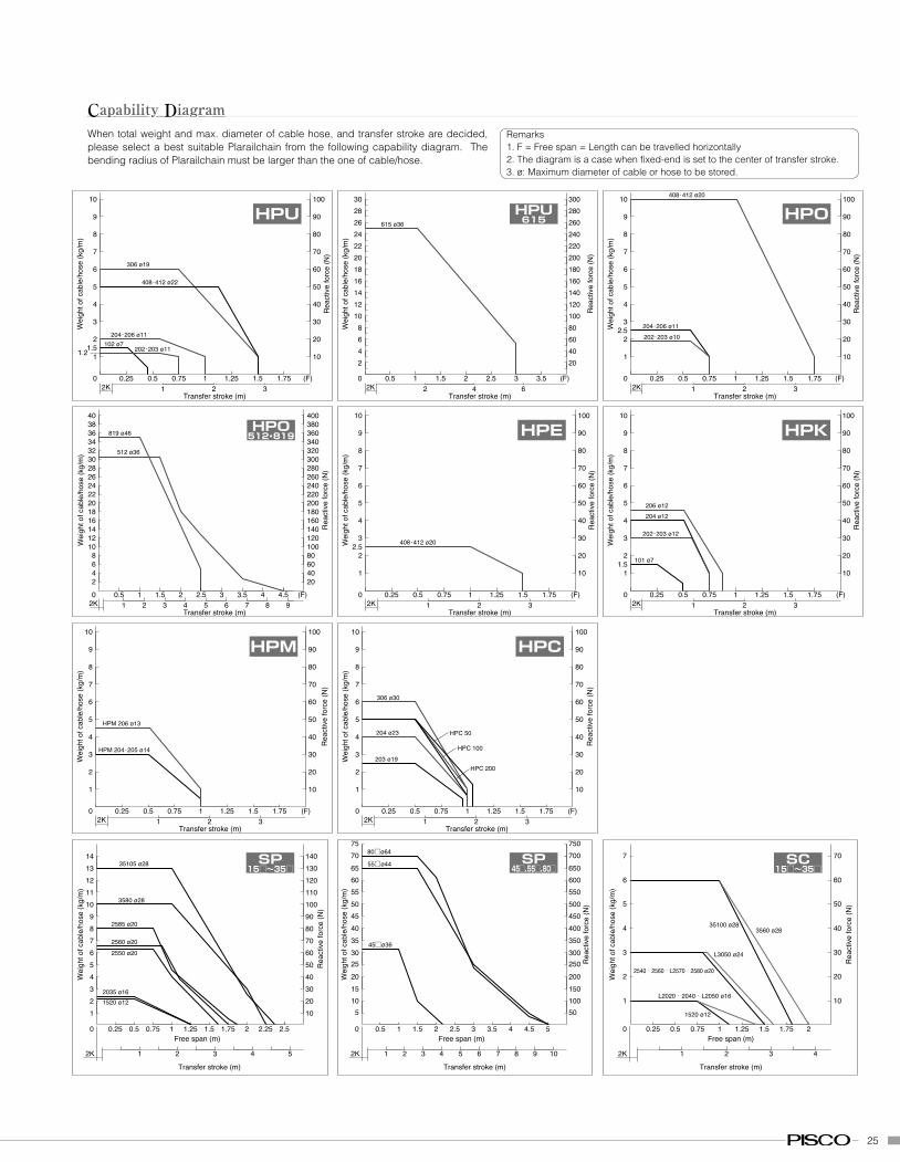
Capability DiagramWhen total weight and max. diameter of cable hose, and transfer stroke are decided, please select a best suitable Plarailchain from the following capability diagram. The bending radius of Plarailchain must be larger than the one of cable/hose.
Remarks1. F = Free span = Length can be travelled horizontally2. The diagram is a case when fixed-end is set to the center of transfer stroke.3. ø: Maximum diameter of cable or hose to be stored.
26
Safety Instructions for fixing storage items (tubings/ cables)This instruction is only examples to decrease the wear and tear of tubings/ cables inside the Plarailchain, but do not guarantee the effect for all types. As such, please conduct test use before actual operation.
1. Storage of tubings/cables1. Please select tubings/cables with less than the minimum-bending radius of plarailchain. In addition, please fix crook of tubings/ cables before installing in Plarailchain.
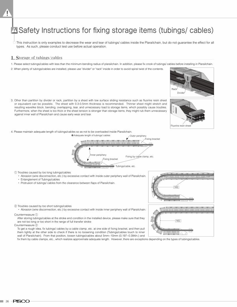
2. When plenty of tubings/cables are installed, please use "divider" or "rack" inside in order to avoid spiral twist of the contents.
3. Other than partition by divider or rack, partition by a sheet with low surface sliding resistance such as fluorine resin sheet or equivalent can be possible. The sheet with 0.3-0.5mm thickness is recommended. Thinner sheet might stretch and resulting wavelike block, bending, overlapping, tear, and unnecessary load to storage items, which possibly cause troubles. Furthermore, when the sheet is too thick or the sheet tension is stronger than storage items, they might rub them unnecessary against inner wall of Plarailchain and cause early wear and tear.
4. Please maintain adequate length of tubings/cables so as not to be overloaded inside Plarailchain.●Adequate length of tubings/ cables
Fixing bracket
Fixing bracket
Tubings/cable, etc.
Fixing by cable clamp, etc.
Fluorine resin sheet
Rack
Divider
① Troubles caused by too long tubings/cables・ Abrasion (wire disconnection, etc.) by excessive contact with inside outer periphery wall of Plarailchain.・ Entanglement of Tubings/cables・ Protrusion of tubings/ cables from the clearance between flaps of Plarailchain.
NG
② Troubles caused by too short tubings/cables・ Abrasion (wire disconnection, etc.) by excessive contact with inside inner periphery wall of Plarailchain.
NG
Countermeasure ①After storing tubings/cables at the stroke end condition in the installed device, please make sure that they are not too long or too short in the range of full transfer stroke
Countermeasure ②To get a rough idea, fix tubings/ cables by a cable clamp, etc. at one side of fixing bracket, and then pull them lightly at the other side to check if there is no loosening condition (Tubings/cables touch to inner wall of Plarailchain). From that position, loosen tubings/cables about 5mm~10mm (0.197~0.394in.) and fix them by cable clamps, etc., which realizes approximate adequate length. However, there are exceptions depending on the types of tubings/cables.
Outer periphery
Inner periphery
27
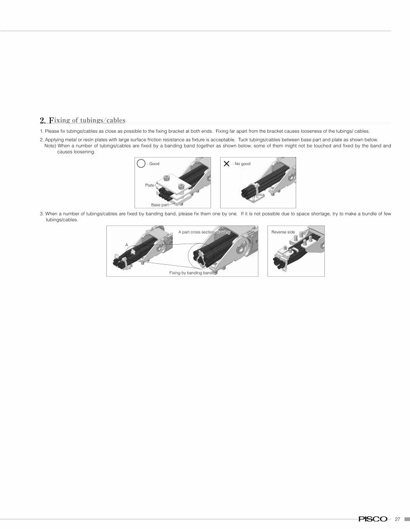
2. Fixing of tubings/cables1. Please fix tubings/cables as close as possible to the fixing bracket at both ends. Fixing far apart from the bracket causes looseness of the tubings/ cables.
2. Applying metal or resin plates with large surface friction resistance as fixture is acceptable. Tuck tubings/cables between base part and plate as shown below.Note) When a number of tubings/cables are fixed by a banding band together as shown below, some of them might not be touched and fixed by the band and
causes loosening.
Plate
Base part
〇 : Good × : No good
3. When a number of tubings/cables are fixed by banding band, please fix them one by one. If it is not possible due to space shortage, try to make a bundle of few tubings/cables.
Fixing by banding band
A
A part cross section drawing Reverse side
28
S=SL+SRSR
Guide-rail length>SR×60%Guide-rail
Guide-railGuide-rail length>SL+K
SLK
K
R
Fixed end
Moving end
S=SL+SRSR
F (Free span)Guide-roller install position<F×80% (*2)
Guide roller
Guide-railGuide-rail length>SL+K
SL
h (*
3)
K
K
R
Fixed end
Moving end
Sub-guide roller (*3)
Bending guide
15~
30º
W
T×2/
3
T×2/
5 an
d m
ore
T
G 15 ~ 30º
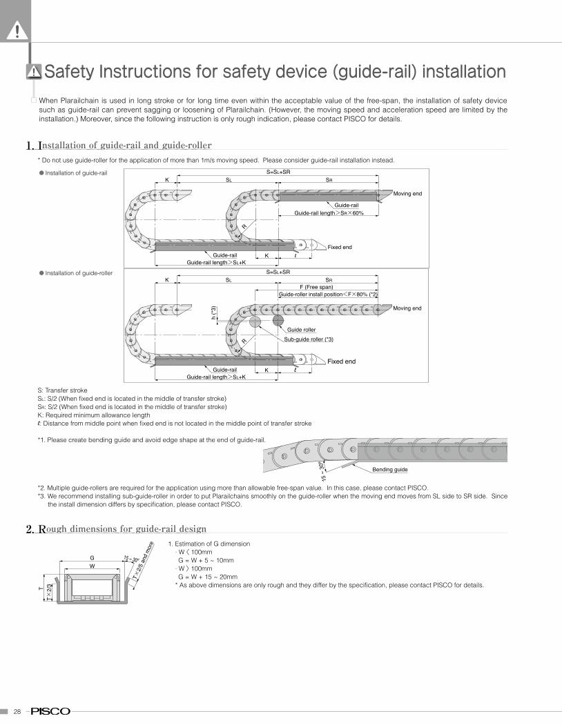
Safety Instructions for safety device (guide-rail) installationWhen Plarailchain is used in long stroke or for long time even within the acceptable value of the free-span, the installation of safety device such as guide-rail can prevent sagging or loosening of Plarailchain. (However, the moving speed and acceleration speed are limited by the installation.) Moreover, since the following instruction is only rough indication, please contact PISCO for details.
1. Installation of guide-rail and guide-roller* Do not use guide-roller for the application of more than 1m/s moving speed. Please consider guide-rail installation instead.
● Installation of guide-rail
● Installation of guide-roller
S: Transfer stroke SL: S/2 (When fixed end is located in the middle of transfer stroke)SR: S/2 (When fixed end is located in the middle of transfer stroke)K: Required minimum allowance length: Distance from middle point when fixed end is not located in the middle point of transfer stroke
*1. Please create bending guide and avoid edge shape at the end of guide-rail.
*2. Multiple guide-rollers are required for the application using more than allowable free-span value. In this case, please contact PISCO.*3. We recommend installing sub-guide-roller in order to put Plarailchains smoothly on the guide-roller when the moving end moves from SL side to SR side. Since
the install dimension differs by specification, please contact PISCO.
2. Rough dimensions for guide-rail design1. Estimation of G dimension
· W � 100mmG = W + 5 ~ 10mm
· W � 100mmG = W + 15 ~ 20mm
* As above dimensions are only rough and they differ by the specification, please contact PISCO for details.
29
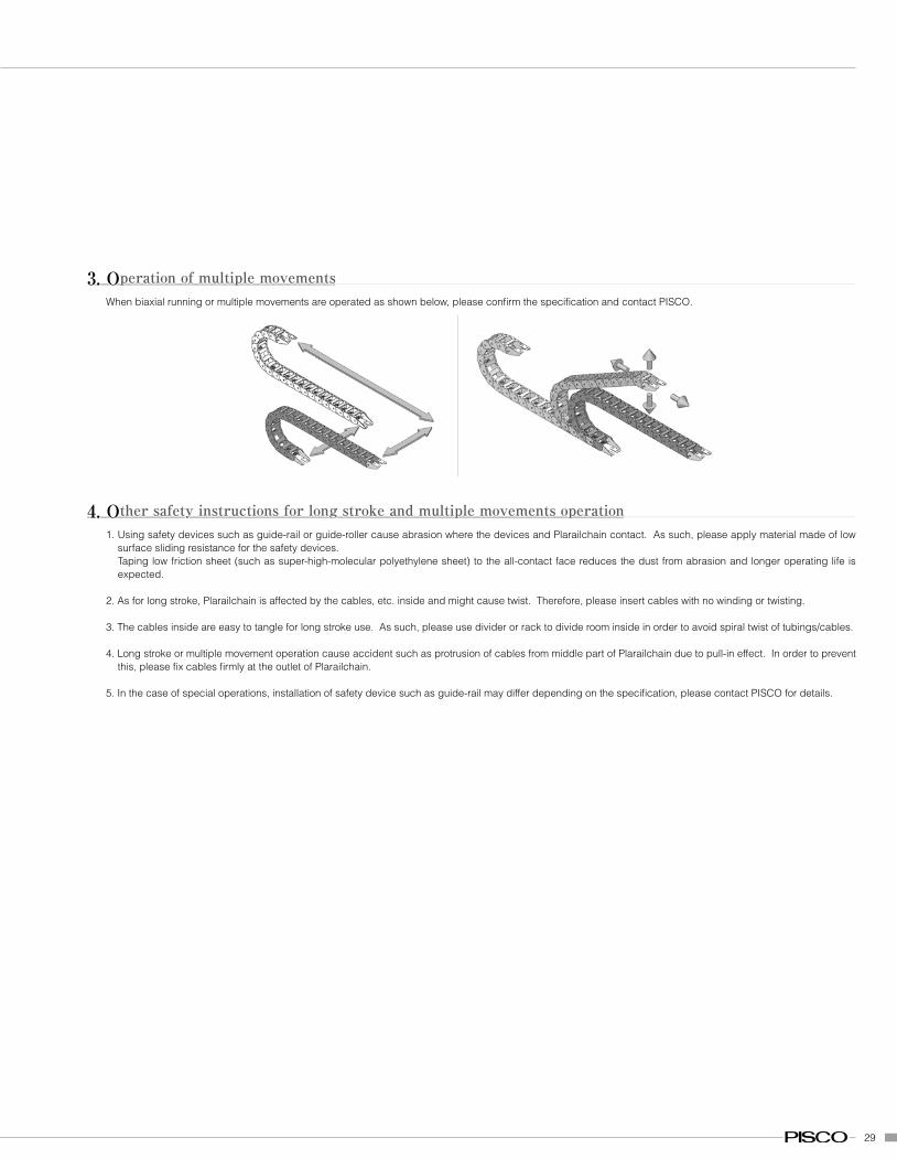
3. Operation of multiple movementsWhen biaxial running or multiple movements are operated as shown below, please confirm the specification and contact PISCO.
4. Other safety instructions for long stroke and multiple movements operation1. Using safety devices such as guide-rail or guide-roller cause abrasion where the devices and Plarailchain contact. As such, please apply material made of low
surface sliding resistance for the safety devices.Taping low friction sheet (such as super-high-molecular polyethylene sheet) to the all-contact face reduces the dust from abrasion and longer operating life is expected.
2. As for long stroke, Plarailchain is affected by the cables, etc. inside and might cause twist. Therefore, please insert cables with no winding or twisting.
3. The cables inside are easy to tangle for long stroke use. As such, please use divider or rack to divide room inside in order to avoid spiral twist of tubings/cables.
4. Long stroke or multiple movement operation cause accident such as protrusion of cables from middle part of Plarailchain due to pull-in effect. In order to prevent this, please fix cables firmly at the outlet of Plarailchain.
5. In the case of special operations, installation of safety device such as guide-rail may differ depending on the specification, please contact PISCO for details.
13
Safety InstructionsThis Safety Instructions aim to prevent personal injury and damage to properties by requiring proper use of PISCO products.
Be certain to follow ISO 4414 and JIS B 8370.
ISO 4414: Pneumatic fluid power … Recommendations for the application of equipment to transmission and control systems.
JIS B 8370: General rules and safety requirements for systems and their components.
This Safety instructions are classified into "Danger", "Warning" and "Caution", depending on the degree of danger or damages caused by
improper use of PISCO products.
: Hazardous conditions. It can cause death or serious personal injury.Danger
: Hazardous conditions depending on usages. Improper Use of PISCO products can case death or serious personal injury.Warning
: Hazardous conditions depending on usages. Improper use of PISCO products can cause personal injury or damages to properties.Caution
* Safety Instructions are subject to change without notice.
: 1. Selection of pneumatic products.(1) A user who is a pneumatic system designer or has sufficient experience and technical expertise should select PISCO products.(2) Due to wide variety of operating conditions and applications for PISCO products, carry out the analysis and evaluation on PISCO products. The
pneumatic system designer is solely responsible for assuring that the user’s requirements are met and that the application presents no health or safety hazards. All designers are required to fully understand the specifications of PISCO products and constitute all systems based on the latest catalog or information, considering any malfunction.
2. Handle pneumatic equipment with enough knowledge and experience.(1) Improper use of compressed air is dangerous. Assembly, operation and maintenance of machines using pneumatic equipment should be conducted
by a person with enough knowledge and experience.3. Do not operate machine / equipment or remove pneumatic equipment until safety is confirmed.
(1) Make sure that preventive measures against falling work-pieces or sudden movements of machine are completed before inspection or maintenance of these machine.
(2) When removing the pneumatic equipment, make sure that the above preventive measures are completed. A compressed air supply and the power supply to the machine must be off, and also the compressed air in the systems must be exhausted.
(3) Restart the machines with care after ensuring to take all preventive measures against sudden movements.
Warning

14
Common Safety Instructions for Products in This CatalogPISCO products are designed and manufactured for use in general industrial machinery and equipment. Be sure to read and follow the instructions below:
: 1. Do not use PISCO products under the following conditions.(1) Beyond the specifications or conditions stated in the catalog or the instructions.(2) Under the direct sunlight or outdoors.(3) Excessive vibrations and impacts.(4) Exposure / adhere to corrosive gas, inflammable gas, chemicals, seawater, water and vapor.** Some products can be used under the condition above (4). Refer to the details of specification and condition of each product.
2. Do not disassemble or modify PISCO products, which affect the performance, function, and basic structure of the product.3. Do not touch the release-ring of push-in fitting when there is a working pressure. The lock may be released by the physical contact, and tube may fly out
or slip out.4. Frequent switchover of compressed air may generate heat, and there is a risk of causing burn injury.5. Avoid any load on PISCO products, such as a tensile strength, twisting and bending. Otherwise there is a risk of causing damage to the products.6. As for applications where threads or tubes swing / rotate, use Rotary Joints, High Rotary Joints or Multi-Circuit Rotary Block only. The other PISCO
products can be damaged in these applications.7. Use only Die Temperature Control Fitting Series, Tube Fitting Stainless SUS316 Series, Tube Fitting Stainless SUS316 Compression Fitting Series or Tube
Fitting Brass Series under the condition of over 60°C (140°F) water or heat medium oil. Other PISCO products can be damaged by head and hydrolysis under the condition above.
8. As for the condition required to dissipate static electricity or provide an antistatic performance, use EG Series fitting and antistatic products only, and do not use other PISCO products. There is a risk that static electricity can cause system defects or failures.
9. Use only Fittings with a characteristic of spatter-proof such as Anti-spatter or Brass Series in a place where flame and weld spatter is produced. There is a risk of causing fire by sparks.
10. Turn off the power supply to PISCO products, and make sure there is no residual air pressure in the pipes and equipment before maintenance. Follow the instructions below in order to ensure safety.
(1) Make sure the safety of all systems related to PISCO products before maintenance.(2) Restart of operation after maintenance shall be proceeded with care after ensuring safety of the system by preventive measures against unexpected
moments of machines and devices where pneumatic equipment is used.(3) Keep enough space for maintenance when designing a circuit.
11. Take safety measures such as providing a protection cover if there is a risk of causing damaged or fires on machine / facilities by a fluid leakage.
Warning
: 1. Remove dusts or drain before piping. They may get into the peripheral machine / facilities and cause malfunction.2. When inserting an ultra-soft tube into push-in fitting, make sure to place an Insert Ring into the tube edge. There is a risk of causing the escape of tube
and a fluid leakage without using an Insert Ring.3. The product incorporating NBR as seal rubber material has a risk of malfunction caused by ozone crack. Ozone exists in high concentrations in static
elimination air, clean-room, and near the high-voltage motors, etc. As a countermeasure, material change from NBR to HNBR or FKM is necessary. Consult with PISCO for more information.
4. Special option “Oil-free” products may cause a very small amount of a fluid leakage. When a fluid medium is liquid or the products are required to be used in harsh environments, contact us for further information.
5. In case of using non-PISCO brand tubes, make sure the tolerance of the outer tube diameter and tube hardness are within the limits of Table 1.
Caution
Table 1. Tube O.D. Tolerance
mm size
Nylon tube Polyurethane tube
(SHORE D63) (SHORE A98)
ø1.8mm - ±0.05mm
ø2mm - ±0.05mm
ø3mm - ±0.15mm
ø4mm ±0.1mm ±0.15mm
ø6mm ±0.1mm ±0.15mm
ø8mm ±0.1mm ±0.15mm
ø10mm ±0.1mm ±0.15mm
ø12mm ±0.1mm ±0.15mm
ø16mm ±0.1mm ±0.15mm
inch size
Nylon tube Polyurethane tube
(SHORE D63) (SHORE A98)
ø1/8 ±0.1mm ±0.15mm
ø5/32 ±0.1mm ±0.15mm
ø3/16 ±0.1mm ±0.15mm
ø1/4 ±0.1mm ±0.15mm
ø5/16 ±0.1mm ±0.15mm
ø3/8 ±0.1mm ±0.15mm
ø1/2 ±0.1mm ±0.15mm
ø5/8 ±0.1mm ±0.15mm
: 1. Do not use PISCO products for the following applications:Equipment used for maintaining / handling human life and body.Equipment used for moving / transporting human.Equipment specifically used for safety purposes.
Danger
15
Tube end
Lock claws
Tube
Sealing
Tube is not fully inserted up to tube end.
: NG: GOOD
7. Instructions for Tube Disconnection(1) Make sure there is no air pressure inside of the tube, before disconnecting it.(2) Push the release-ring of the push-in fitting evenly and deeply enough to pull out the tube toward oneself. By insufficient pushing of the release-ring,
the tube may not be pulled out or damaged by scratch, and tube shavings may remain inside of the fitting, which may cause the leakage later.8. Instructions for Installing a fitting
(1) When installing a fitting, use proper tools to tighten a hexagonal-column or inner hexagonal socket. When inserting a hex key into the inner hexagonal socket of the fitting, be careful so that the tool does not touch lock-claws. The deformation of lock-claws may result in a poor performance of systems or an escape of the tube.
(2) Refer to Table 2 which shows the tightening torque. Do not exceed these limits to tighten a thread. Excessive tightening may break the thread part or deform the gasket to cause a fluid leakage. Tightening thread with tightening torque lower than these limits may cause a loosened thread or a fluid leakage. Since the sealability is affected by the processing condition of the installing part, adjust the tightening torque or correct the installing part, according to the condition.
(3) Adjust the tube direction while tightening thread within these limits, since some PISCO products are not rotatable after the installation.
Table 2. Tightening Torque, Sealock Color and Gasket Material
Thread type Thread size Tightening torque Sealock color Gasket materials
M3×0.5 0.7N·m (0.52lbf·ft)
M5×0.8 1.0 ~ 1.5N·m (0.74 ~ 1.11lbf·ft) SPCC+NBR
M6×1.0 2.0 ~ 2.7N·m (1.48 ~ 1.99lbf·ft) SUS304+NBR
Metric thread M3×0.5 0.7N·m (0.52 lbf·ft) n/a
M5×0.8 1.0 ~ 1.5N·m (0.74 ~ 1.11lbf·ft) POM (Polyacetal)
M6×0.75 0.8 ~ 1.0N·m (0.59 ~ 0.74lbf·ft)
M8×0.75 1.0 ~ 2.0N·m (0.74 ~ 1.48lbf·ft)
R1/8 4.5 ~ 6.5N·m (3.32 ~ 4.79lbf·ft)
Taper pipe thread
R1/4 7 ~ 9N·m (5.16 ~ 6.64lbf·ft) White n/a
R3/8 12.5 ~ 14.5N·m (9.22 ~ 10.70lbf·ft)
R1/2 20 ~ 22N·m (14.75 ~ 16.23lbf·ft)
Unified thread No. 10-32UNF 1.0 ~ 1.5N·m (0.74 ~ 1.11lbf·ft) n/a SPCC+NBR, SUS304+NBR
1/16-27NPT 4.5 ~ 6.5N·m (3.32 ~ 4.79lbf·ft)
National Pipe Thread Taper
1/8-27NPT 4.5 ~ 6.5N·m (3.32 ~ 4.79lbf·ft)
(American standard)
1/4-18NPT 7 ~ 9N·m (5.16 ~ 6.64lbf·ft) White n/a
3/8-18NPT 12.5 ~ 14.5N·m (9.22 ~ 10.70lbf·ft)
1/2-14NPT 20 ~ 22N·m (14.75 ~ 16.23lbf·ft)
* These values may differ for some products. Refer to each specification as well.
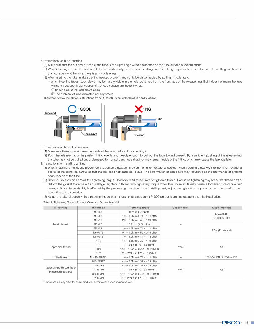
6. Instructions for Tube Insertion(1) Make sure that the cut end surface of the tube is at a right angle without a scratch on the tube surface or deformations.(2) When inserting a tube, the tube needs to be inserted fully into the push-in fitting until the tubing edge touches the tube end of the fitting as shown in
the figure below. Otherwise, there is a risk of leakage.(3) After inserting the tube, make sure it is inserted properly and not to be disconnected by pulling it moderately.
* When inserting tubes, Lock-claws may be hardly visible in the hole, observed from the front face of the release-ring. But it does not mean the tube will surely escape. Major causes of the tube escape are the followings;① Shear drop of the lock-claws edge② The problem of tube diameter (usually small)
Therefore, follow the above instructions from (1) to (3), even lock-claws is hardly visible
16
9. Instructions for removing a fitting(1) When removing a fitting, use proper tools to loosen a hexagonal-column or an inner hex hexagonal socket. When inserting a hex key into the
inner hex hexagonal socket of the fitting, be careful so that the tool does not touch lock-claws. The deformation of lock-claws may result in a poor performance of systems or an escape of the tube.
(2) Remove the sealant stuck on the mating equipment. The remained sealant may get into the peripheral equipment and cause malfunctions.10. Arrange piping avoiding any load on fittings and tubes such as twist, tensile, moment load, shaking and physical impact. These may cause damages to
fittings, tube deformations, bursting and the escape of tubes.11. Impact caused by dropping or the like may lead to damage to the product and a fluid leakage.
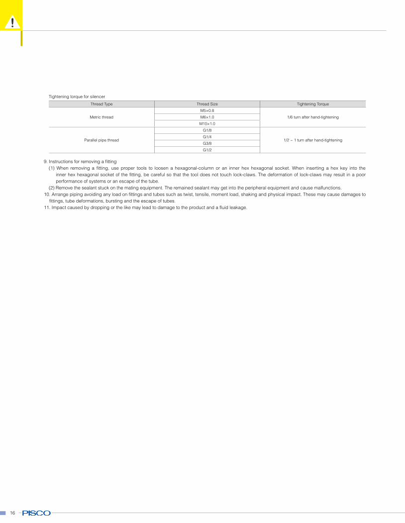
Tightening torque for silencer
Thread Type Thread Size Tightening Torque
Metric thread
M5×0.8
1/6 turn after hand-tighteningM6×1.0
M10×1.0
Parallel pipe thread
G1/8
1/2 ~ 1 turn after hand-tighteningG1/4
G3/8
G1/2