planning and deisgn of common duct (new)
15
Moh and Associates, Inc. Planning and Designing of Common Duct
Transcript of planning and deisgn of common duct (new)

Moh and Associates, Inc.
Planning and Designing
of
Common Duct

2
ContentI. PrefaceII. Brief IntroductionIII. Development in TaiwanIV. MAA’s Experience on Common
Duct EngineeringV. Conclusion

3
Definition
The structure accommodates two or more kinds of public utilities and its own drainage, ventilation, lighting, communication, power or security system.
I. Preface
E T W

4
Function of Common Duct
Avoid road excavationMaintain Urban AppearanceEfficient Use of Underground SpaceEasy Maintenance

5
Main Ducts
Supplier Ducts
Branch Duct
Cable Trench/C.C.Box
II. Brief Introduction
Main DuctSupplier DuctSupplier Duct

6
Main Ducts
Accommodate large diameter, high voltage or numerous passage main pipeline system
Do not directly connect with users
Mostly installed under main roads
Equipped with Walkway, Monitoring, Lighting, Ventilating and Drainage System

7
Main Ducts
ESH
Rectangular—Open Cut
E T W

8
Circular—Shield Tunnel/Pipe Jacking
Main Ducts

9
Main Duct — Utility types accommodatedType of Utility Material of Utility Characteristics of utility and conditions of taking in Accept or not
● Being able to tie in with the space and profile of CD
● High excavation frequency
● Being able to tie in with the space and profile of CD
● High excavation frequency
● Life maintaining utility
● Being able to tie in with the profile of CD
● Life maintaining utility
● Pressure pipes
● Toxic gas
● Gravity flow utility
● Profile can't tie in with CD
● Gravity flow utility● Profile can't tie in with CD● Generating toxic gas
X
X
○
○
○
○
Drainage RCP/BOX
Sewage DIP/RCP
Water supply DIP
Oil/Gas supply DIP/SP
Power Cable
Telecommunication Cable

10
Special units ConfigurationStructures to maintain the operation of utility
institution or CD itself, installed at the position that utility institution needs or at specified interval.Special units contain:
•For CD operation─Workers Exit/Entrance, Natural Ventilation Inlet,Ventilator Ventilation Outlet
•For Utility Needs─Branch Unit, Cable/Pipe Joint Unit, Material Inlet

11
Main Duct
Ventilator Ventilation Outlet
Workers Exit/Entrance
Material Inlet
Material Inlet
BranchDuct

12
Workers Exit/Entrance
•For the convenience of workers exit and entrance shall be located at sidewalk
•Installed at 800~1,000m interval, may be combined with natural ventilation inlet

13
Natural Ventilation Inlet
•Induct air naturally for CD
•Installed in turns with Ventilator Vent at 200m intervals
•Better to set up at road medians

14
Ventilator Ventilation Outlet
•Using ventilator to exhaust the air of CD
•Installed in turns with natural vent at 200m intervals
•Better to set up at road medians
15
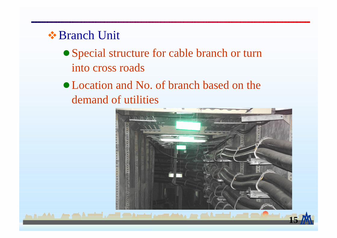
Branch Unit
•Special structure for cable branch or turn into cross roads
•Location and No. of branch based on the demand of utilities