![pISSN: 0256-1115 DOI: 10.1007/s11814-017-0004-6 INVITED ... · the tray properly. In this article, by using commercial CFX code and based on the experimental work [22] a CFD model](https://static.fdocuments.us/doc/165x107/5eac432fdcaa19699f34fbe7/pissn-0256-1115-doi-101007s11814-017-0004-6-invited-the-tray-properly-in.jpg)
pISSN: 0256-1115 DOI: 10.1007/s11814-015-0219-3 … · Abstract −Compression systems with...
11
764 Korean J. Chem. Eng., 33(3), 764-774 (2016) DOI: 10.1007/s11814-015-0219-3 pISSN: 0256-1115 eISSN: 1975-7220 INVITED REVIEW PAPER † To whom correspondence should be addressed. E-mail: [email protected] Copyright by The Korean Institute of Chemical Engineers. Case study of surge avoidance design for centrifugal compressor systems during emergency shut-down (ESD) Se-jin Pak * , Ju Woung Yoon * , Seojin Kim * , Felicia Salim * , Jaihyo Lee ** , and In-Won Kim * ,† *Department of Chemical Engineering, Konkuk University, 120, Neungdong-ro, Gwangjin-gu, Seoul 05029, Korea **Department of Mechanical Engineering, Konkuk University, 120, Neungdong-ro, Gwangjin-gu, Seoul 05029, Korea (Received 19 July 2015 • accepted 17 October 2015) Abstract- Compression systems with centrifugal compressors are widely used in gas involving processes. Surge pro- tection system design is crucial in avoiding any damage in abnormal circumstances such as emergency shutdown (ESD), start-up, coast-down operation, and normal shutdown. We analyzed four cases of existing centrifugal compres- sor systems, three CO 2 compression systems and one off-gas compression system, to study the surge protection avail- ability during ESD. All compression systems were working well at normal operating condition, but some systems could not avoid surge during ESD. To check the surge cases, the surge criteria flowchart was suggested and surge analysis through dynamic simulation was done using a commercial process simulator. To avoid a surge during ESD, a sensitiv- ity analysis was done while considering the following process parameters: pre-stroke time, anti-surge valve (ASV) type, capacity, and stroke time. We optimized ASV design using response surface method with two selected parameters from the sensitivity study, ASV capacity and stroke time. Finally, the installation of the hot gas recycle system was analyzed to avoid surge occurrence. Keywords: Compression System, Compressor Surge, Emergency Shutdown (ESD), Surge Protection, Dynamic Simulation INTRODUCTION Most gas involving processes, such as a gas injecting oil field, pipeline compression, gas and oil separation process (GOSP), gas liquefaction, refinery and petrochemical process, require a compres- sion system, and a centrifugal compressor is widely used in such processes with its advantages mainly in operability, reliability and high capacity. Furthermore, the centrifugal compressor is a crucial part of plant because of its high cost and importance in operation such that if the compressor is in trouble, the whole plant should be shut down in most of the cases. Thus, compressor protection is highly required in avoiding any damage at an abnormal circum- stance such as emergency shutdown (ESD), start-up, coast down operation, and normal shutdown as well as during normal opera- tion. Especially, surge protection is important to protect the com- pressor from surge over the range of compressor operations [1]. Surge is defined as an unstable operation condition of centrifu- gal compressors when the operation point of the compressor is on the left of the surge line, which is the stability limit in the compres- sor performance graph [2]. Surge protection, especially, is a cru- cial part in design of a centrifugal compression system, and whole system verification is necessary to be done using a dynamic simu- lation [3]. It is dynamic in nature, so a steady-state model may not be adequate to address issues associated with transient operations, such as startup operation, compressor surge protection, and stabil- ity of operation during turn-down. Most engineering companies struggle with practical difficulties. The difficulties include (1) the whole system verification is believed to be possible at far later stage with all detailed design information available, (2) engineering company lacks a dynamic simulation spe- cialist and even smaller number of specialists for surge protection system, (3) the responsibility of verification resides somewhere among process engineer, mechanical engineer, control engineer and simulation specialist, (4) the working procedure requires high in- volvement of project manager, engineering manager and procure- ment engineer to gather all relevant data, and (5) redesign is poten- tially required at the final stage after the verification. For many cases, installing a hot-gas recycle system, which is also called a bypass system, can be the possible solution, but it will cause many changes in most of engineering disciplines such as process, mechanical, piping including plot, even down to structural and civil, which can cause huge cost impact incurring from other pro- curement and/or schedule delays to the whole EPC project. In principle, a process system engineer is highly required to have proper guidelines regarding all the impact of design parameters to design the surge protection system, but practically not. The main purpose of this paper is to provide a clear picture of how much impact all of the design parameters have on the surge protection and to optimize the value of surge parameters based on the results of the study. It can be used during the full-course of project devel- opment, such as FEED, EPC bidding, and EPC. CENTRIFUGAL COMPRESSION SYSTEM AND SURGE ANALYSIS A generalized centrifugal compression system is shown in Fig.
Transcript of pISSN: 0256-1115 DOI: 10.1007/s11814-015-0219-3 … · Abstract −Compression systems with...
764
Korean J. Chem. Eng., 33(3), 764-774 (2016)DOI: 10.1007/s11814-015-0219-3
pISSN: 0256-1115eISSN: 1975-7220
INVITED REVIEW PAPER
†To whom correspondence should be addressed.E-mail: [email protected] by The Korean Institute of Chemical Engineers.
Case study of surge avoidance design for centrifugal compressor systemsduring emergency shut-down (ESD)
Se-jin Pak*, Ju Woung Yoon*, Seojin Kim*, Felicia Salim*, Jaihyo Lee**, and In-Won Kim*,†
*Department of Chemical Engineering, Konkuk University, 120, Neungdong-ro, Gwangjin-gu, Seoul 05029, Korea**Department of Mechanical Engineering, Konkuk University, 120, Neungdong-ro, Gwangjin-gu, Seoul 05029, Korea
(Received 19 July 2015 • accepted 17 October 2015)
Abstract−Compression systems with centrifugal compressors are widely used in gas involving processes. Surge pro-tection system design is crucial in avoiding any damage in abnormal circumstances such as emergency shutdown(ESD), start-up, coast-down operation, and normal shutdown. We analyzed four cases of existing centrifugal compres-sor systems, three CO2 compression systems and one off-gas compression system, to study the surge protection avail-ability during ESD. All compression systems were working well at normal operating condition, but some systems couldnot avoid surge during ESD. To check the surge cases, the surge criteria flowchart was suggested and surge analysisthrough dynamic simulation was done using a commercial process simulator. To avoid a surge during ESD, a sensitiv-ity analysis was done while considering the following process parameters: pre-stroke time, anti-surge valve (ASV) type,capacity, and stroke time. We optimized ASV design using response surface method with two selected parameters fromthe sensitivity study, ASV capacity and stroke time. Finally, the installation of the hot gas recycle system was analyzedto avoid surge occurrence.
Keywords: Compression System, Compressor Surge, Emergency Shutdown (ESD), Surge Protection, Dynamic Simulation
INTRODUCTION
Most gas involving processes, such as a gas injecting oil field,pipeline compression, gas and oil separation process (GOSP), gasliquefaction, refinery and petrochemical process, require a compres-sion system, and a centrifugal compressor is widely used in suchprocesses with its advantages mainly in operability, reliability andhigh capacity. Furthermore, the centrifugal compressor is a crucialpart of plant because of its high cost and importance in operationsuch that if the compressor is in trouble, the whole plant should beshut down in most of the cases. Thus, compressor protection ishighly required in avoiding any damage at an abnormal circum-stance such as emergency shutdown (ESD), start-up, coast downoperation, and normal shutdown as well as during normal opera-tion. Especially, surge protection is important to protect the com-pressor from surge over the range of compressor operations [1].
Surge is defined as an unstable operation condition of centrifu-gal compressors when the operation point of the compressor is onthe left of the surge line, which is the stability limit in the compres-sor performance graph [2]. Surge protection, especially, is a cru-cial part in design of a centrifugal compression system, and wholesystem verification is necessary to be done using a dynamic simu-lation [3]. It is dynamic in nature, so a steady-state model may notbe adequate to address issues associated with transient operations,such as startup operation, compressor surge protection, and stabil-ity of operation during turn-down.
Most engineering companies struggle with practical difficulties.The difficulties include (1) the whole system verification is believedto be possible at far later stage with all detailed design informationavailable, (2) engineering company lacks a dynamic simulation spe-cialist and even smaller number of specialists for surge protectionsystem, (3) the responsibility of verification resides somewhereamong process engineer, mechanical engineer, control engineer andsimulation specialist, (4) the working procedure requires high in-volvement of project manager, engineering manager and procure-ment engineer to gather all relevant data, and (5) redesign is poten-tially required at the final stage after the verification.
For many cases, installing a hot-gas recycle system, which is alsocalled a bypass system, can be the possible solution, but it will causemany changes in most of engineering disciplines such as process,mechanical, piping including plot, even down to structural andcivil, which can cause huge cost impact incurring from other pro-curement and/or schedule delays to the whole EPC project.
In principle, a process system engineer is highly required to haveproper guidelines regarding all the impact of design parameters todesign the surge protection system, but practically not. The mainpurpose of this paper is to provide a clear picture of how muchimpact all of the design parameters have on the surge protectionand to optimize the value of surge parameters based on the resultsof the study. It can be used during the full-course of project devel-opment, such as FEED, EPC bidding, and EPC.
CENTRIFUGAL COMPRESSION SYSTEMAND SURGE ANALYSIS
A generalized centrifugal compression system is shown in Fig.
Case study of surge avoidance design for centrifugal compressor systems during emergency shut-down (ESD) 765
Korean J. Chem. Eng.(Vol. 33, No. 3)
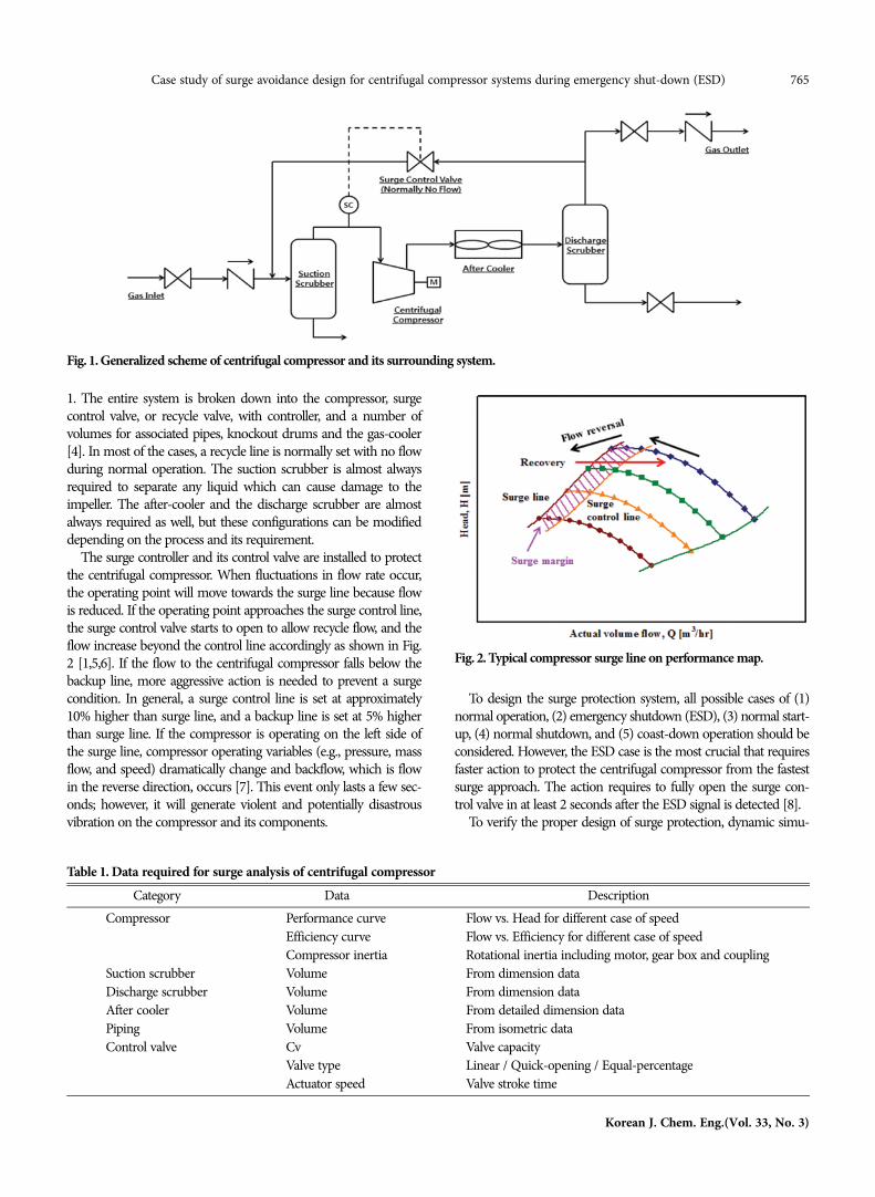
1. The entire system is broken down into the compressor, surgecontrol valve, or recycle valve, with controller, and a number ofvolumes for associated pipes, knockout drums and the gas-cooler[4]. In most of the cases, a recycle line is normally set with no flowduring normal operation. The suction scrubber is almost alwaysrequired to separate any liquid which can cause damage to theimpeller. The after-cooler and the discharge scrubber are almostalways required as well, but these configurations can be modifieddepending on the process and its requirement.
The surge controller and its control valve are installed to protectthe centrifugal compressor. When fluctuations in flow rate occur,the operating point will move towards the surge line because flowis reduced. If the operating point approaches the surge control line,the surge control valve starts to open to allow recycle flow, and theflow increase beyond the control line accordingly as shown in Fig.2 [1,5,6]. If the flow to the centrifugal compressor falls below thebackup line, more aggressive action is needed to prevent a surgecondition. In general, a surge control line is set at approximately10% higher than surge line, and a backup line is set at 5% higherthan surge line. If the compressor is operating on the left side ofthe surge line, compressor operating variables (e.g., pressure, massflow, and speed) dramatically change and backflow, which is flowin the reverse direction, occurs [7]. This event only lasts a few sec-onds; however, it will generate violent and potentially disastrousvibration on the compressor and its components.
To design the surge protection system, all possible cases of (1)normal operation, (2) emergency shutdown (ESD), (3) normal start-up, (4) normal shutdown, and (5) coast-down operation should beconsidered. However, the ESD case is the most crucial that requiresfaster action to protect the centrifugal compressor from the fastestsurge approach. The action requires to fully open the surge con-trol valve in at least 2 seconds after the ESD signal is detected [8].
To verify the proper design of surge protection, dynamic simu-
Fig. 1. Generalized scheme of centrifugal compressor and its surrounding system.
Fig. 2. Typical compressor surge line on performance map.
Table 1. Data required for surge analysis of centrifugal compressorCategory Data Description
Compressor Performance curve Flow vs. Head for different case of speedEfficiency curve Flow vs. Efficiency for different case of speedCompressor inertia Rotational inertia including motor, gear box and coupling
Suction scrubber Volume From dimension dataDischarge scrubber Volume From dimension dataAfter cooler Volume From detailed dimension dataPiping Volume From isometric dataControl valve Cv Valve capacity
Valve type Linear / Quick-opening / Equal-percentageActuator speed Valve stroke time
766 S.-j. Pak et al.
March, 2016
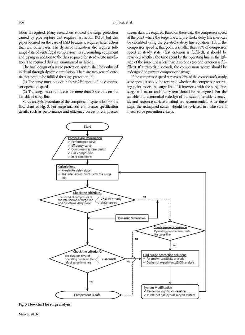
lation is required. Many researchers studied the surge protectioncaused by pipe rupture that requires fast action [9,10], but thispaper focused on the case of ESD because it requires faster actionthan any other cases. The dynamic simulation also requires full-range data of centrifugal compressors, its surrounding equipmentand piping in addition to the data required for steady-state simula-tion. The required data are summarized in Table 1.
The final design of a surge protection system shall be evaluatedin detail through dynamic simulation. There are two general crite-ria that need to be fulfilled for surge protection [8]:
(1) The surge must not occur above 75% speed of the compres-sor operation speed.
(2) The surge must not occur for more than 2 seconds on theleft-side of surge line.
Surge analysis procedure of the compression system follows theflow chart of Fig. 3. For surge analysis, compressor specificationdetails, such as performance and efficiency curves of compressor
stream data, are required. Based on these data, the compressor speedat the point where the surge line and pre-stroke delay line meet canbe calculated using the pre-stroke delay line equation [11]. If thecompressor speed at that point is smaller than 75% of compressorspeed at steady state, (first criterion is fulfilled), it should bereviewed whether the time spent by the operating line in the left-side of the surge line is less than 2 seconds (second criterion is ful-filled). If it exceeds 2 seconds, the compression system should beredesigned to prevent compressor damage.
If the compressor speed surpasses 75% of the compressor’s steadystate speed, it should be reviewed whether the compressor operat-ing point meets the surge line. If it intersects with the surge line,surge will occur and the system should be redesigned. For thesuitable and economical redesign of the system, sensitivity analy-sis and response surface method are recommended. After thesesteps, the redesigned system should be reviewed to make sure itmeets surge prevention criteria.
Fig. 3. Flow chart for surge analysis.
Case study of surge avoidance design for centrifugal compressor systems during emergency shut-down (ESD) 767
Korean J. Chem. Eng.(Vol. 33, No. 3)
DYNAMIC SIMULATION OF A BASE CASEOF COMPRESSION SYSTEM
A one-stage compression system with cold gas recycle being usedin a gas-oil separation plant (GOSP) was selected for a base caseanalysis. All operating conditions and mass balance are the sameas the original design except simplified piping isometric for sensi-tivity study. For the surge analysis during ESD, dynamic simula-tion involved using a commercial process simulator.1. Base Case of Compression System with Cold Gas Recycle
The base case system is a CO2 compression system using a sin-gle stage centrifugal compressor. The piping isometrics are simpli-fied for sensitivity study purpose. The compressor suction pipingand ASV discharge piping are set to be 36-inch in diameter andstraight 100 m in length, and the compressor discharge piping andASV suction piping are set to be 24-inch in diameter and straight100 m in length as well. All pipes have no elevation change. Alsothe compressor suction scrubber and discharge scrubber are re-moved for simplicity on the basis that no liquid is formed at anycase. Volume of the compressor after-Cooler is not considered onlyfor sensitivity purpose as well. A quick-opening butterfly-type anti-surge valve (ASV) was chosen and its capacity is 3,000 USgpm. The
details of design specification are summarized in the second col-umn of Table 2.
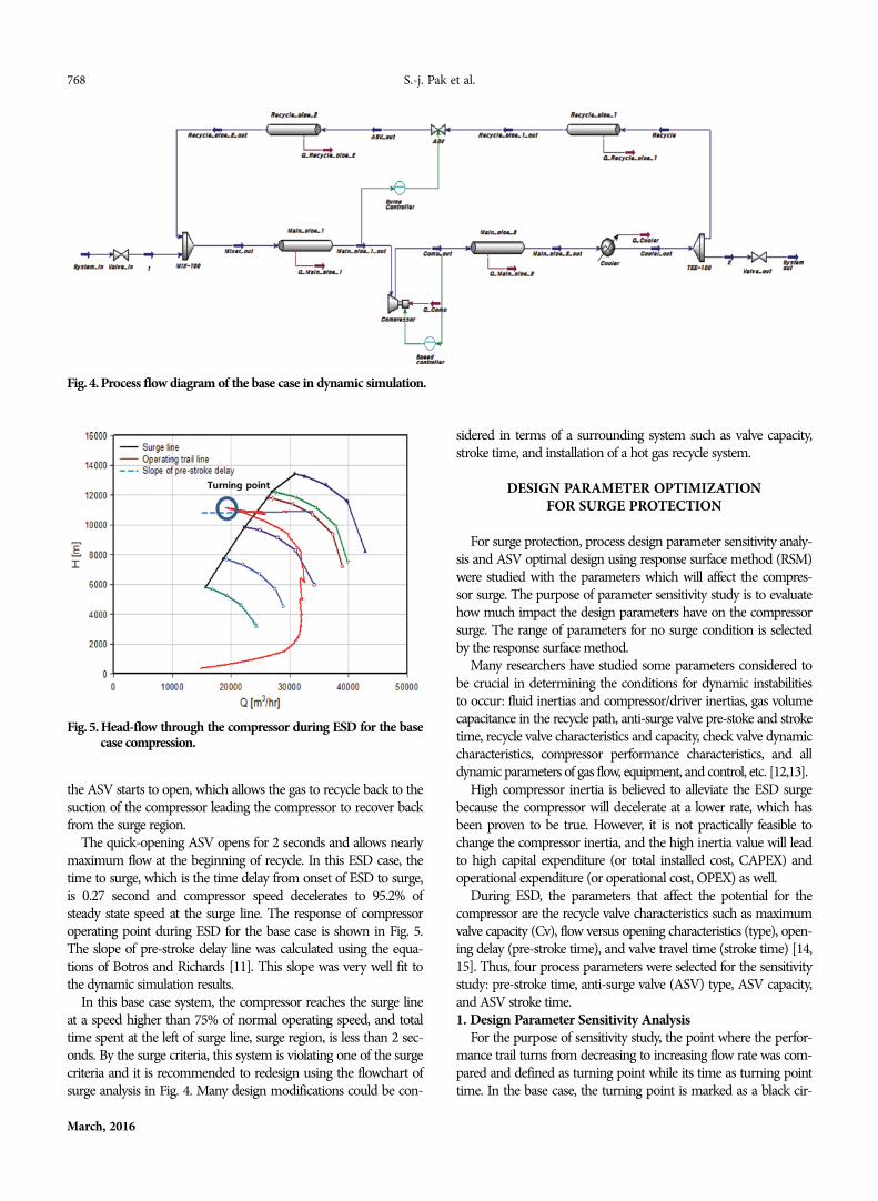
A simplified configuration of surge analysis in dynamic simula-tion is shown in Fig. 4. The commercial process simulator program,Aspen HYSYS, is used for dynamic simulation.2. Dynamic Simulation of the Base Case System
For dynamic simulation, two time-related parameters are selected.One is pre-stroke time, which is the time required for a signal tobe delivered from ESD detection to start of valve opening, and isset to be 0.2 second. The other is valve stroke time, which is thetime required to fully open the surge control valve, which is set tobe 2 seconds.
To generate a surge during ESD, a step-wise scenario of ESDneeds to be incorporated using an event scheduler in the program.Time sequences of ESD scenario are set: normal operation from 0second, ESD occurred at 5 seconds, ASV started to open at 5.2 sec-onds due to 0.2 second pre-stroke time, and lastly, dynamic simu-lation ended in 30 seconds.
Onset of ESD, or power off, the speed of compressor starts todecelerate, which is governed by its combined rotational inertia,and as a result, the volumetric flow rate of compressor starts todecrease as well. After the pre-stroke time, 0.2 seconds after ESD,
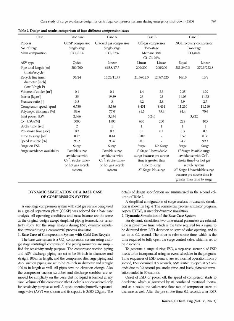
Table 2. Design and results comparison of four different compression casesCase Base case Case A Case B Case C
Process GOSP compressor Cracked gas compressor Off-gas compressor NGL recovery compressorNo. of stage Single-stage Single-stage Two-stage Two-stageMain composition CO2 81% CO2 87% Methane 38%
C1-C3 76%CO2 84%
ASV type Quick Linear Linear Linear Equal LinearPipe total length [m]
(main/recycle)200/200 645.8/17.7 200/200 200/200 281.2/47.3 279.3/222.8
Recycle line innerdiameter [inch](low P/high P)
36/24 15.25/11.75 21.56/12.5 12.5/7.625 16/10 10/8
Volume of cooler [m3] 0.1 0.1 1.4 2.3 2.25 1.29Inertia [kg.m2] 25 19.39 25 25 14.05 11.73Pressure ratio [-] 3.8 3 6.2 2.8 3.9 2.7Compressor speed [rpm] 6,780 8,386 8,431 8,431 11,210 11,210Polytropic efficiency [%] 83.6 77.0 81.5 75.4 84.4 70.6Inlet power [kW] 2,466 3,334 5,245 3,822Cv [USGPM] 3000 1500 600 200 228 103Stroke time [sec] 2 1 1 1 1 1Pre-stroke time [sec] 0.2 0.3 0.1 0.1 0.3 0.3Time to surge [sec] 0.27 0.44 0.09 - 0.52 0.06Speed at surge [%] 95.2 93.6 98.3 - 94.7 99.3Surge on ESD Surge Surge Surge No Surge Surge SurgeSurge avoidance availability Possible surge
avoidance withCv↑, stroke time↓or hot gas recycle
system
Possible surgeavoidance with
Cv↑, stroke time↓or hot gas recycle
system
1st Stage: Unavoidablesurge because pre-stroke
time is greater thantime to surge
2nd Stage: No surge
1st Stage: Possible surgeavoidance with Cv↑,
stroke time↓ or hot gasrecycle system
2nd Stage: Unavoidable surgebecause pre-stroke time isgreater than time to surge
768 S.-j. Pak et al.
March, 2016
the ASV starts to open, which allows the gas to recycle back to thesuction of the compressor leading the compressor to recover backfrom the surge region.
The quick-opening ASV opens for 2 seconds and allows nearlymaximum flow at the beginning of recycle. In this ESD case, thetime to surge, which is the time delay from onset of ESD to surge,is 0.27 second and compressor speed decelerates to 95.2% ofsteady state speed at the surge line. The response of compressoroperating point during ESD for the base case is shown in Fig. 5.The slope of pre-stroke delay line was calculated using the equa-tions of Botros and Richards [11]. This slope was very well fit tothe dynamic simulation results.
In this base case system, the compressor reaches the surge lineat a speed higher than 75% of normal operating speed, and totaltime spent at the left of surge line, surge region, is less than 2 sec-onds. By the surge criteria, this system is violating one of the surgecriteria and it is recommended to redesign using the flowchart ofsurge analysis in Fig. 4. Many design modifications could be con-
sidered in terms of a surrounding system such as valve capacity,stroke time, and installation of a hot gas recycle system.
DESIGN PARAMETER OPTIMIZATIONFOR SURGE PROTECTION
For surge protection, process design parameter sensitivity analy-sis and ASV optimal design using response surface method (RSM)were studied with the parameters which will affect the compres-sor surge. The purpose of parameter sensitivity study is to evaluatehow much impact the design parameters have on the compressorsurge. The range of parameters for no surge condition is selectedby the response surface method.
Many researchers have studied some parameters considered tobe crucial in determining the conditions for dynamic instabilitiesto occur: fluid inertias and compressor/driver inertias, gas volumecapacitance in the recycle path, anti-surge valve pre-stoke and stroketime, recycle valve characteristics and capacity, check valve dynamiccharacteristics, compressor performance characteristics, and alldynamic parameters of gas flow, equipment, and control, etc. [12,13].
High compressor inertia is believed to alleviate the ESD surgebecause the compressor will decelerate at a lower rate, which hasbeen proven to be true. However, it is not practically feasible tochange the compressor inertia, and the high inertia value will leadto high capital expenditure (or total installed cost, CAPEX) andoperational expenditure (or operational cost, OPEX) as well.
During ESD, the parameters that affect the potential for thecompressor are the recycle valve characteristics such as maximumvalve capacity (Cv), flow versus opening characteristics (type), open-ing delay (pre-stroke time), and valve travel time (stroke time) [14,15]. Thus, four process parameters were selected for the sensitivitystudy: pre-stroke time, anti-surge valve (ASV) type, ASV capacity,and ASV stroke time.1. Design Parameter Sensitivity Analysis
For the purpose of sensitivity study, the point where the perfor-mance trail turns from decreasing to increasing flow rate was com-pared and defined as turning point while its time as turning pointtime. In the base case, the turning point is marked as a black cir-
Fig. 4. Process flow diagram of the base case in dynamic simulation.
Fig. 5. Head-flow through the compressor during ESD for the basecase compression.
Case study of surge avoidance design for centrifugal compressor systems during emergency shut-down (ESD) 769
Korean J. Chem. Eng.(Vol. 33, No. 3)
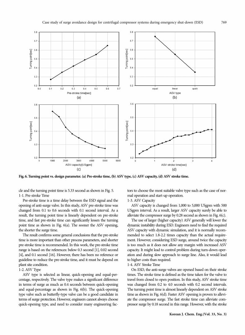
cle and the turning point time is 5.33 second as shown in Fig. 5.1-1. Pre-stroke Time
Pre-stroke time is a time delay between the ESD signal and theopening of anti-surge valve. In this study, ASV pre-stroke time waschanged from 0.1 to 0.6 seconds with 0.1 second interval. As aresult, the turning point time is linearly dependent on pre-stroketime, and fast pre-stroke time can significantly lessen the turningpoint time as shown in Fig. 6(a). The sooner the ASV opening,the shorter the surge time.
The result confirms some general conclusions that the pre-stroketime is more important than other process parameters, and shorterpre-stroke time is recommended. In this work, the pre-stroke timerange is based on the references: below 0.3 second [1], 0.02 second[4], and 0.1 second [16]. However, there has been no reference orguideline to reduce the pre-stroke time, and it must be depend onplant site condition.1-2. ASV Type
ASV type is selected as linear, quick-opening and equal-per-centage, respectively. The valve type makes a significant differencein terms of surge as much as 0.4 seconds between quick-openingand equal-percentage as shown in Fig. 6(b). The quick-openingtype valve such as butterfly-type valve can be a good candidate interms of surge protection. However, engineers cannot always choosequick-opening type, and need to consider many engineering fac-
tors to choose the most suitable valve type such as the case of nor-mal operation and start-up operation.1-3. ASV Capacity
ASV capacity is changed from 1,000 to 5,000 USgpm with 500USgpm interval. As a result, larger ASV capacity surely be able toalleviate the compressor surge by 0.28 second as shown in Fig. 6(c).
The use of larger (higher capacity) ASV generally will lower thedynamic instability during ESD. Engineers need to find the requiredASV capacity with dynamic simulation, and it is normally recom-mended to select 1.8-2.2 times capacity than the actual require-ment. However, considering ESD surge, around twice the capacityis too much as it does not allow any margin with increased ASVcapacity. It might lead to control problem during turn-down oper-ation and during slow approach to surge line. Also, it would leadto higher costs than required.1-4. ASV Stroke Time
On ESD, the anti-surge valves are opened based on their stroketimes. The stroke time is defined as the time taken for the valve totravel from closed to open position. In this study, ASV stroke timewas changed from 0.2 to 4.0 seconds with 0.2 second intervals.The turning point time is almost linearly dependent on ASV stroketime as shown in Fig. 6(d). Faster ASV opening is proven to allevi-ate the compressor surge. The fast stroke time can alleviate com-pressor surge by 0.18 second in this range. However, with the stroke
Fig. 6. Turning point vs. design parameter. (a) Pre-stroke time, (b) ASV type, (c) ASV capacity, (d) ASV stroke time.
770 S.-j. Pak et al.
March, 2016
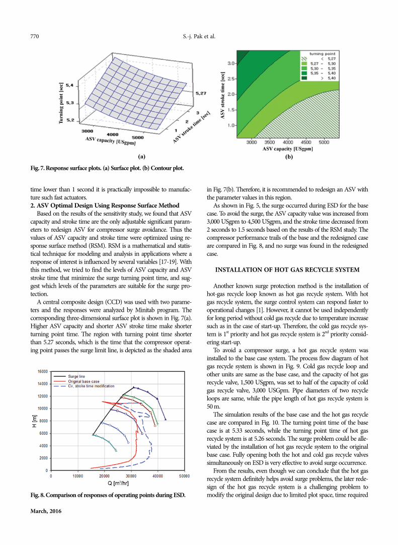
time lower than 1 second it is practically impossible to manufac-ture such fast actuators.2. ASV Optimal Design Using Response Surface Method
Based on the results of the sensitivity study, we found that ASVcapacity and stroke time are the only adjustable significant param-eters to redesign ASV for compressor surge avoidance. Thus thevalues of ASV capacity and stroke time were optimized using re-sponse surface method (RSM). RSM is a mathematical and statis-tical technique for modeling and analysis in applications where aresponse of interest is influenced by several variables [17-19]. Withthis method, we tried to find the levels of ASV capacity and ASVstroke time that minimize the surge turning point time, and sug-gest which levels of the parameters are suitable for the surge pro-tection.
A central composite design (CCD) was used with two parame-ters and the responses were analyzed by Minitab program. Thecorresponding three-dimensional surface plot is shown in Fig. 7(a).Higher ASV capacity and shorter ASV stroke time make shorterturning point time. The region with turning point time shorterthan 5.27 seconds, which is the time that the compressor operat-ing point passes the surge limit line, is depicted as the shaded area
in Fig. 7(b). Therefore, it is recommended to redesign an ASV withthe parameter values in this region.
As shown in Fig. 5, the surge occurred during ESD for the basecase. To avoid the surge, the ASV capacity value was increased from3,000 USgpm to 4,500 USgpm, and the stroke time decreased from2 seconds to 1.5 seconds based on the results of the RSM study. Thecompressor performance trails of the base and the redesigned caseare compared in Fig. 8, and no surge was found in the redesignedcase.
INSTALLATION OF HOT GAS RECYCLE SYSTEM
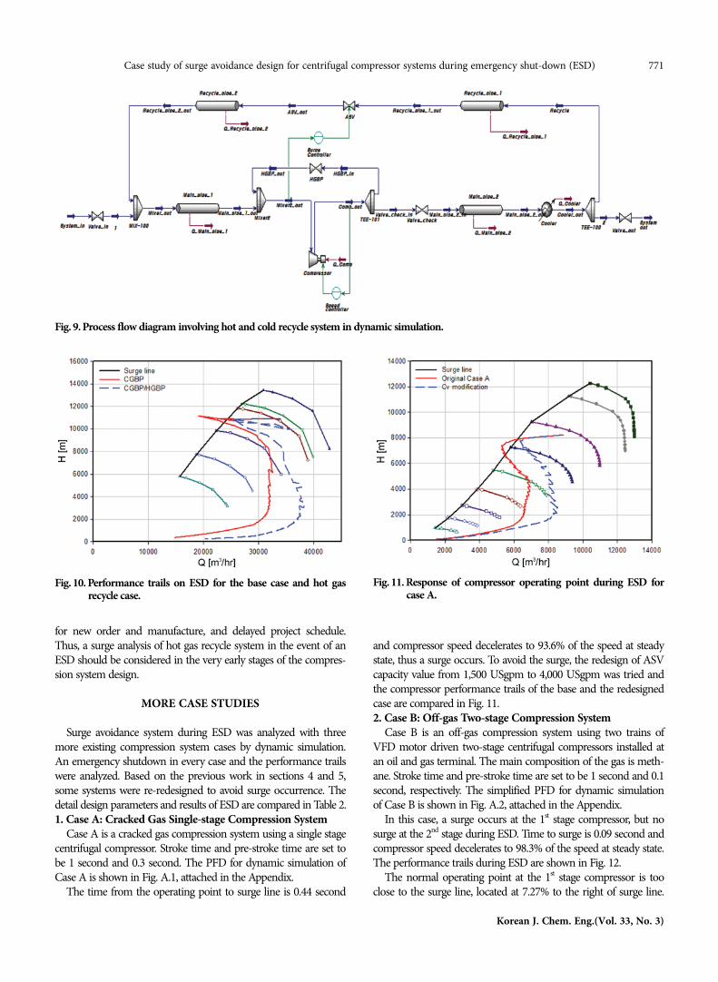
Another known surge protection method is the installation ofhot-gas recycle loop known as hot gas recycle system. With hotgas recycle system, the surge control system can respond faster tooperational changes [1]. However, it cannot be used independentlyfor long period without cold gas recycle due to temperature increasesuch as in the case of start-up. Therefore, the cold gas recycle sys-tem is 1st priority and hot gas recycle system is 2nd priority consid-ering start-up.
To avoid a compressor surge, a hot gas recycle system wasinstalled to the base case system. The process flow diagram of hotgas recycle system is shown in Fig. 9. Cold gas recycle loop andother units are same as the base case, and the capacity of hot gasrecycle valve, 1,500 USgpm, was set to half of the capacity of coldgas recycle valve, 3,000 USGpm. Pipe diameters of two recycleloops are same, while the pipe length of hot gas recycle system is50 m.
The simulation results of the base case and the hot gas recyclecase are compared in Fig. 10. The turning point time of the basecase is at 5.33 seconds, while the turning point time of hot gasrecycle system is at 5.26 seconds. The surge problem could be alle-viated by the installation of hot gas recycle system to the originalbase case. Fully opening both the hot and cold gas recycle valvessimultaneously on ESD is very effective to avoid surge occurrence.
From the results, even though we can conclude that the hot gasrecycle system definitely helps avoid surge problems, the later rede-sign of the hot gas recycle system is a challenging problem tomodify the original design due to limited plot space, time required
Fig. 7. Response surface plots. (a) Surface plot. (b) Contour plot.
Fig. 8. Comparison of responses of operating points during ESD.
Case study of surge avoidance design for centrifugal compressor systems during emergency shut-down (ESD) 771
Korean J. Chem. Eng.(Vol. 33, No. 3)
for new order and manufacture, and delayed project schedule.Thus, a surge analysis of hot gas recycle system in the event of anESD should be considered in the very early stages of the compres-sion system design.
MORE CASE STUDIES
Surge avoidance system during ESD was analyzed with threemore existing compression system cases by dynamic simulation.An emergency shutdown in every case and the performance trailswere analyzed. Based on the previous work in sections 4 and 5,some systems were re-redesigned to avoid surge occurrence. Thedetail design parameters and results of ESD are compared in Table 2.1. Case A: Cracked Gas Single-stage Compression System
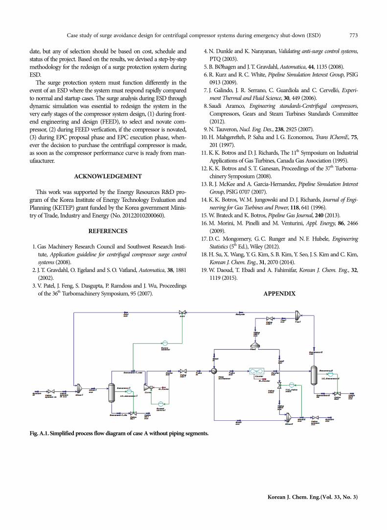
Case A is a cracked gas compression system using a single stagecentrifugal compressor. Stroke time and pre-stroke time are set tobe 1 second and 0.3 second. The PFD for dynamic simulation ofCase A is shown in Fig. A.1, attached in the Appendix.
The time from the operating point to surge line is 0.44 second
and compressor speed decelerates to 93.6% of the speed at steadystate, thus a surge occurs. To avoid the surge, the redesign of ASVcapacity value from 1,500 USgpm to 4,000 USgpm was tried andthe compressor performance trails of the base and the redesignedcase are compared in Fig. 11.2. Case B: Off-gas Two-stage Compression System
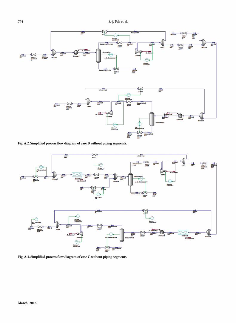
Case B is an off-gas compression system using two trains ofVFD motor driven two-stage centrifugal compressors installed atan oil and gas terminal. The main composition of the gas is meth-ane. Stroke time and pre-stroke time are set to be 1 second and 0.1second, respectively. The simplified PFD for dynamic simulationof Case B is shown in Fig. A.2, attached in the Appendix.
In this case, a surge occurs at the 1st stage compressor, but nosurge at the 2nd stage during ESD. Time to surge is 0.09 second andcompressor speed decelerates to 98.3% of the speed at steady state.The performance trails during ESD are shown in Fig. 12.
The normal operating point at the 1st stage compressor is tooclose to the surge line, located at 7.27% to the right of surge line.
Fig. 9. Process flow diagram involving hot and cold recycle system in dynamic simulation.
Fig. 10. Performance trails on ESD for the base case and hot gasrecycle case.
Fig. 11. Response of compressor operating point during ESD forcase A.

772 S.-j. Pak et al.
March, 2016
As a consequence, the surge margin or operating window is sig-nificantly reduced. The pre-stroke time of this case is 0.1 second,but the time to the surge line is only 0.09 second. Thus, we cannotavoid a surge problem during ESD even though the compressorsurge does not occur during normal operation. In this case, manyredesign cases can be studied, but basically a different compressorshould have been selected at an early stage in terms of a surge pro-tection system.3. Case C: NGL Recovery Two-stage Compression System
Case C is the part of an NGL recovery facility which includesacid gas compression using two-stage compressors. Stroke timeand pre-stroke time are set to be 1 second and 0.3 second. Thesimplified PFD for dynamic simulation of Case C is shown in Fig.A.3, attached in the Appendix.
In this case a surge occurs at both stages. Time to surge is 0.52and 0.06 second, compressor speed decelerates to 94.7% and 99.3%of the speed at steady state at the surge line. The performancetrails during ESD are shown in Fig. 13.
For the 1st stage of Case C, the installation of a hot gas recycle
system helps in avoiding a surge, and the ASV capacity in cold gasrecycle system is 250 USgpm, and that in the hot gas recycle sys-tem is 250 USgpm. Like the 1st stage of Case B, the 2nd stage ofCase C could not avoid surge because the pre-stroke time of thiscase is 0.3 second, but the time to the surge line is only 0.06 second.
CONCLUSIONS
A surge protection system for a centrifugal compressor is crucialto avoid any damage during emergency shut-down. Four cases ofexisting centrifugal compressor systems were analyzed to study thesurge protection availability during ESD. The surge criteria flow-chart was suggested and surge analysis through dynamic simula-tion was done using a commercial process simulator.
As a result of sensitivity study, it is found that ASV capacity andstroke time are the only adjustable significant parameters for surgeprotection system during ESD. With those findings, response sur-face method was applied to find an optimized design of a surgeprotection system. A hot-gas recycle system can be another candi-
Fig. 13. Response of compressor operating point during ESD for Case C. (a) 1st Stage. (b) 2nd Stage.
Fig. 12. Response of compressor operating point during ESD for Case B. (a) 1st Stage. (b) 2nd Stage.
Case study of surge avoidance design for centrifugal compressor systems during emergency shut-down (ESD) 773
Korean J. Chem. Eng.(Vol. 33, No. 3)
date, but any of selection should be based on cost, schedule andstatus of the project. Based on the results, we devised a step-by-stepmethodology for the redesign of a surge protection system duringESD.
The surge protection system must function differently in theevent of an ESD where the system must respond rapidly comparedto normal and startup cases. The surge analysis during ESD throughdynamic simulation was essential to redesign the system in thevery early stages of the compressor system design, (1) during front-end engineering and design (FEED), to select and novate com-pressor, (2) during FEED verfication, if the compressor is novated,(3) during EPC proposal phase and EPC execution phase, when-ever the decision to purchase the centrifugal compressor is made,as soon as the compressor performance curve is ready from man-ufaucturer.
ACKNOWLEDGEMENT
This work was supported by the Energy Resources R&D pro-gram of the Korea Institute of Energy Technology Evaluation andPlanning (KETEP) grant funded by the Korea government Minis-try of Trade, Industry and Energy (No. 20122010200060).
REFERENCES
1. Gas Machinery Research Council and Southwest Research Insti-tute, Application guideline for centrifugal compressor surge controlsystems (2008).
2. J. T. Gravdahl, O. Egeland and S. O. Vatland, Automatica, 38, 1881(2002).
3. V. Patel, J. Feng, S. Dasgupta, P. Ramdoss and J. Wu, Proceedingsof the 36th Turbomachinery Symposium, 95 (2007).
4. N. Dunkle and K. Narayanan, Validating anti-surge control systems,PTQ (2003).
5. B. BØhagen and J. T. Gravdahl, Automatica, 44, 1135 (2008).6. R. Kurz and R. C. White, Pipeline Simulation Interest Group, PSIG
0913 (2009).7. J. Galindo, J. R. Serrano, C. Guardiola and C. Cervelló, Experi-
ment Thermal and Fluid Science, 30, 449 (2006).8. Saudi Aramco, Engineering standards-Centrifugal compressors,
Compressors, Gears and Steam Turbines Standards Committee(2012).
9. N. Tauveron, Nucl. Eng. Des., 238, 2925 (2007).10. H. Mahgerefteh, P. Saha and I. G. Economou, Trans IChemE, 75,
201 (1997).11. K. K. Botros and D. J. Richards, The 11th Symposium on Industrial
Applications of Gas Turbines, Canada Gas Association (1995).12. K. K. Botros and S. T. Ganesan, Proceedings of the 37th Turboma-
chinery Symposium (2008).13. R. J. McKee and A. Garcia-Hernandez, Pipeline Simulation Interest
Group, PSIG 0707 (2007).14. K. K. Botros, W. M. Jungowski and D. J. Richards, Journal of Engi-
neering for Gas Turbines and Power, 118, 641 (1996).15. W. Brateck and K. Botros, Pipeline Gas Journal, 240 (2013).16. M. Morini, M. Pinelli and M. Venturini, Appl. Energy, 86, 2466
(2009).17. D. C. Mongomery, G. C. Runger and N. F. Hubele, Engineering
Statistics (5th Ed.), Wiley (2012).18. H. Su, X. Wang, Y. G. Kim, S. B. Kim, Y. Seo, J. S. Kim and C. Kim,
Korean J. Chem. Eng., 31, 2070 (2014).19. W. Daoud, T. Ebadi and A. Fahimifar, Korean J. Chem. Eng., 32,
1119 (2015).
APPENDIX
Fig. A.1. Simplified process flow diagram of case A without piping segments.
774 S.-j. Pak et al.
March, 2016
Fig. A.3. Simplified process flow diagram of case C without piping segments.
Fig. A.2. Simplified process flow diagram of case B without piping segments.


![pISSN: 0256-1115 DOI: 10.1007/s11814-014-0274-1 INVITED ... · cellulose, cow leather, wool fiber, NR, etc [4-8]. For example, graft-ing butyl acrylate onto cellulose enhances its](https://static.fdocuments.us/doc/165x107/5e1ea453d4a5ba6aa702865c/pissn-0256-1115-doi-101007s11814-014-0274-1-invited-cellulose-cow-leather.jpg)


