Pipe Freeze Protection. 2 XL-Trace Systems Pipe Freeze Protection and Flow Maintenance.
18
Pipe Freeze Protection
-
Upload
brittney-garrett -
Category
Documents
-
view
220 -
download
1
Transcript of Pipe Freeze Protection. 2 XL-Trace Systems Pipe Freeze Protection and Flow Maintenance.
Pipe Freeze Protection
2
XL-Trace Systems
•Pipe Freeze Protection and Flow Maintenance
3
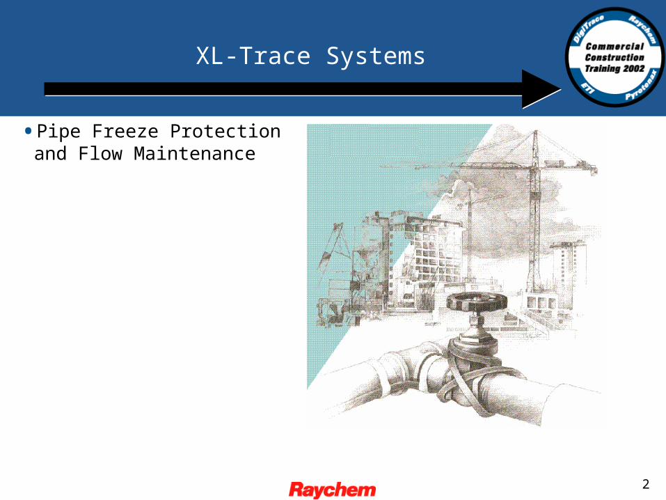
System Overview
4
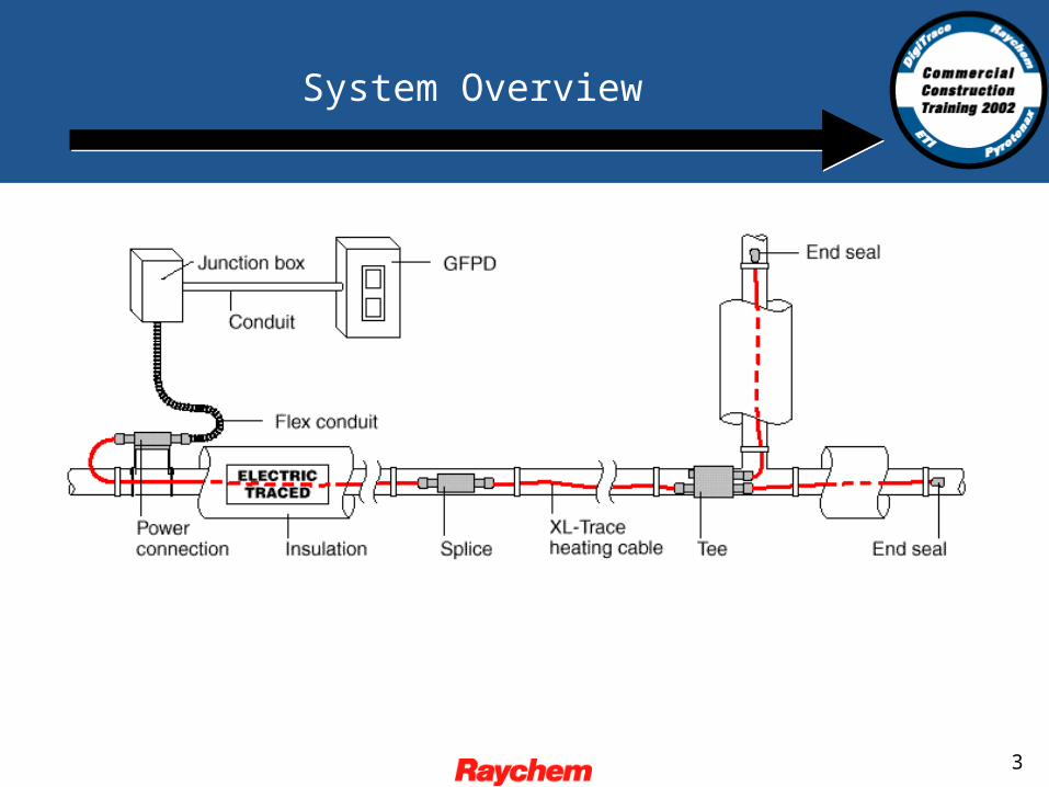
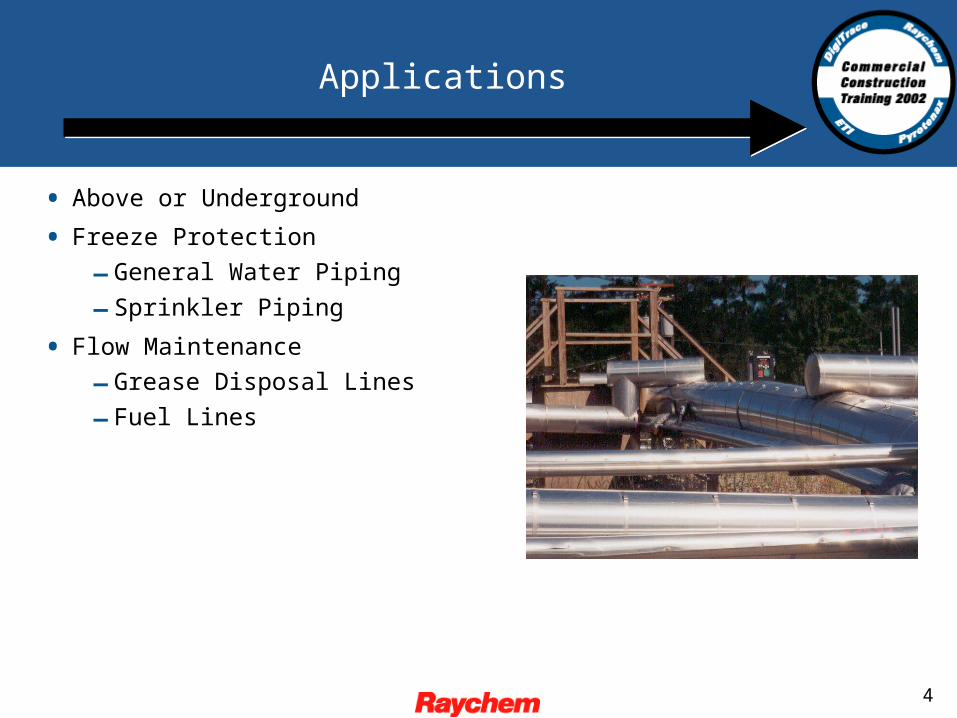
Applications
• Above or Underground
• Freeze Protection
– General Water Piping
– Sprinkler Piping
• Flow Maintenance
– Grease Disposal Lines
– Fuel Lines
5
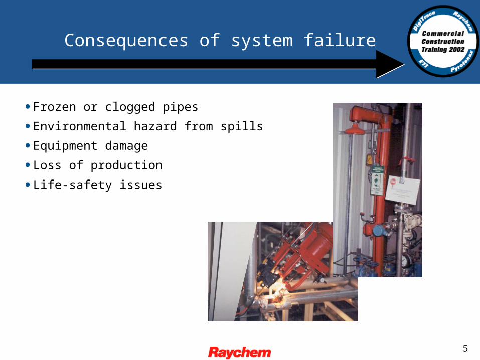
Consequences of system failure
•Frozen or clogged pipes
•Environmental hazard from spills
•Equipment damage
•Loss of production
•Life-safety issues
6
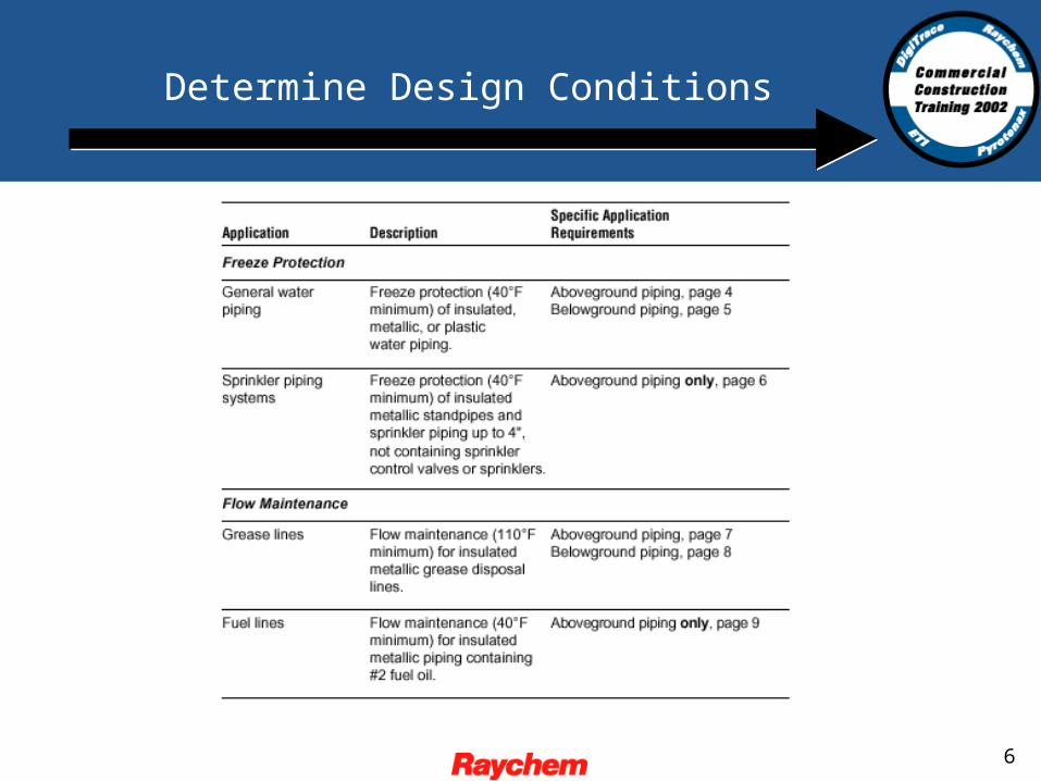
Determine Design Conditions
7
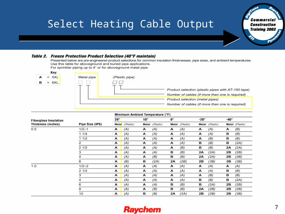
Select Heating Cable Output
8
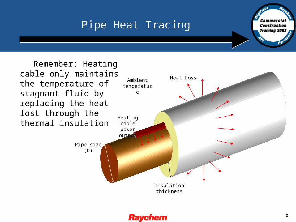
Remember: Heating cable only maintains the temperature of stagnant fluid by replacing the heat lost through the thermal insulation
Pipe Heat Tracing
Heating cable power output
Insulation thickness
Pipe size (D)
Heat LossAmbient temperature
9
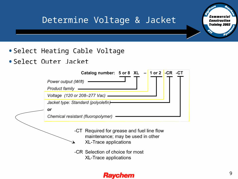
Determine Voltage & Jacket
•Select Heating Cable Voltage
•Select Outer Jacket
10
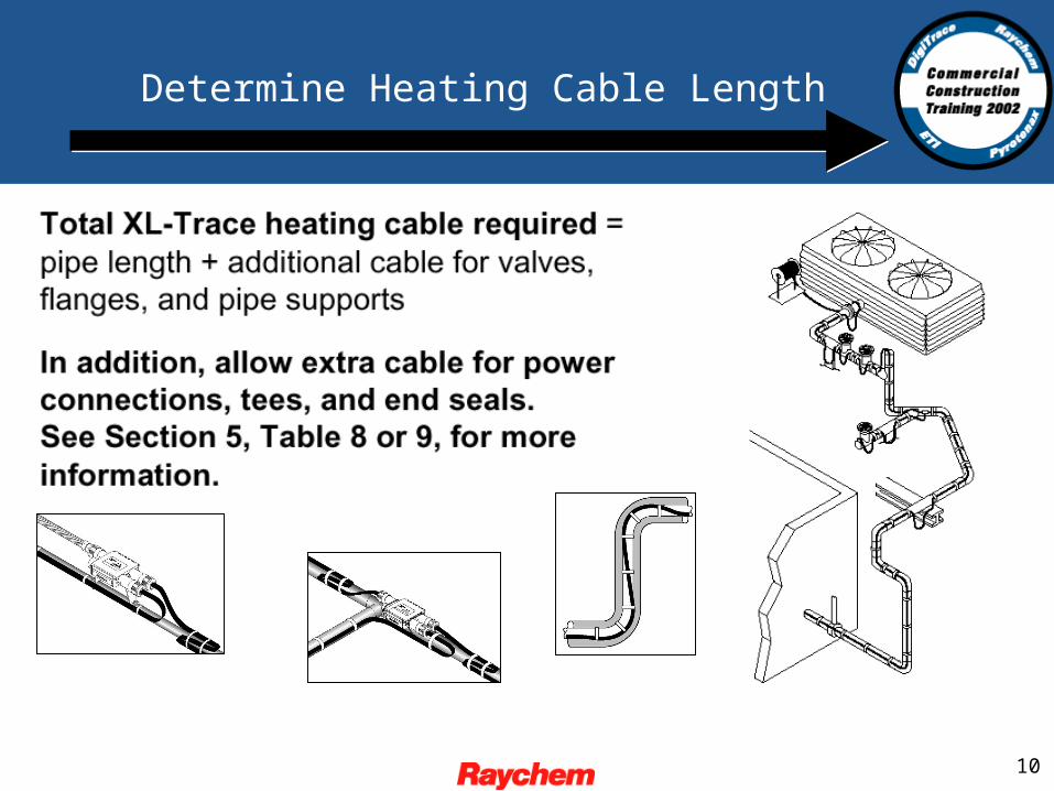
Determine Heating Cable Length
11
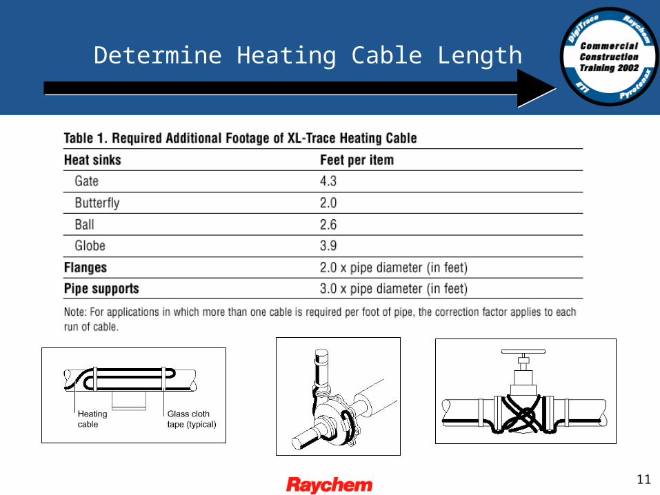
Determine Heating Cable Length
12
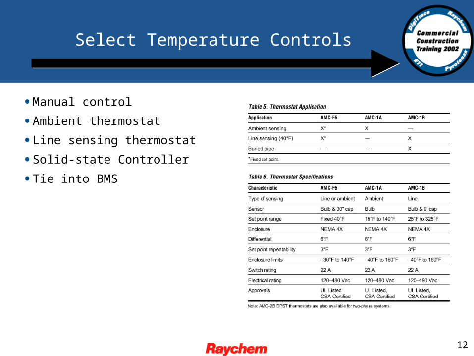
Select Temperature Controls
•Manual control
•Ambient thermostat
•Line sensing thermostat
•Solid-state Controller
•Tie into BMS
13
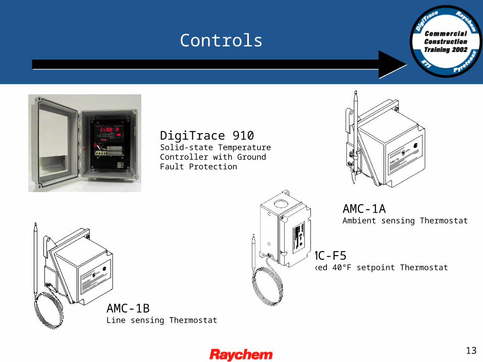
Controls
AMC-1BLine sensing Thermostat
AMC-1AAmbient sensing Thermostat
AMC-F5Fixed 40°F setpoint Thermostat
DigiTrace 910Solid-state Temperature Controller with Ground Fault Protection
14
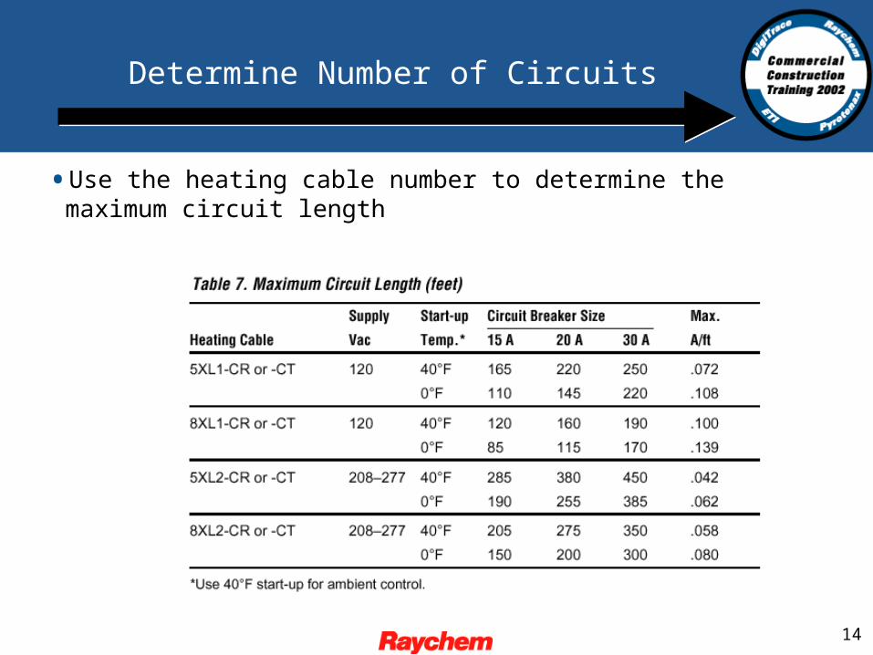
Determine Number of Circuits
•Use the heating cable number to determine the maximum circuit length
15
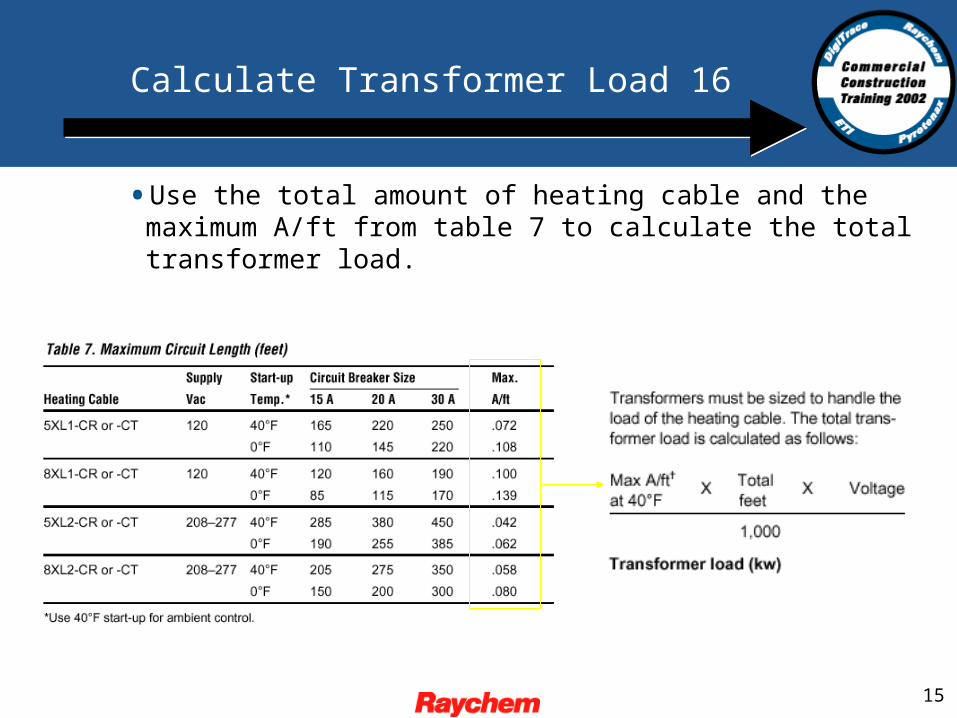
Calculate Transformer Load 16
•Use the total amount of heating cable and the maximum A/ft from table 7 to calculate the total transformer load.
16
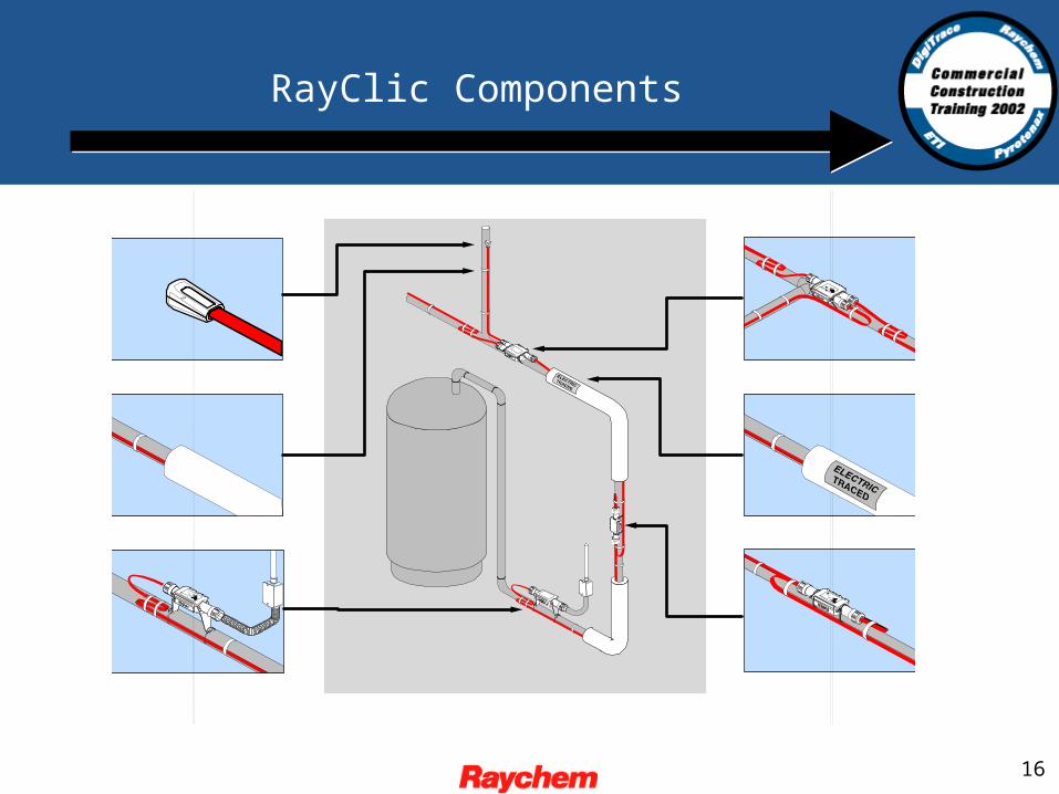
RayClic Components
17
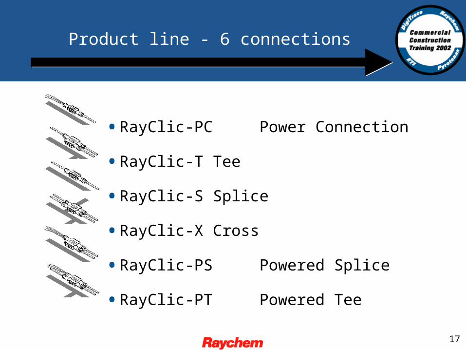
Product line - 6 connections
•RayClic-PC Power Connection
•RayClic-T Tee
•RayClic-S Splice
•RayClic-X Cross
•RayClic-PS Powered Splice
•RayClic-PT Powered Tee
18
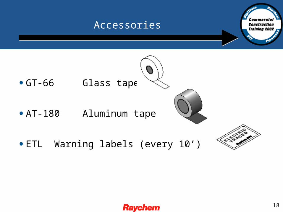
Accessories
•GT-66 Glass tape
•AT-180 Aluminum tape
•ETL Warning labels (every 10’)
![Pipe Freeze Protection and Flow Maintenance design guide.… · Pipe Freeze Protection and Flow Maintenance XL-Trace ... Sprinkler piping Freeze protection (40°F [4°C] minimum)](https://static.fdocuments.us/doc/165x107/5b6951b37f8b9af23e8de25f/pipe-freeze-protection-and-flow-design-guide-pipe-freeze-protection-and-flow.jpg)