piglet manual
38
PIGLET ANALYSIS AND DESIGN OF PILE GROUPS M. F. RANDOLPH VERSION 5.1 RELEASED MAY 2004 (MANUAL LAST EDITED MAY 2007)
description
piglet manual
Transcript of piglet manual
PIGLET
ANALYSIS AND DESIGN OF
PILE GROUPS
M. F. RANDOLPH
VERSION 5.1
RELEASED MAY 2004
(MANUAL LAST EDITED MAY 2007)
PIGLET
ANALYSIS AND DESIGN OF
PILE GROUPS
M. F. RANDOLPH
VERSION 5.1: RELEASED MAY 2004
(MANUAL LAST EDITED MAY 2007)
The accuracy of this program has been checked over a period of years, and it is believed that, within the limitations of the analytical model, results obtained with the program are correct. However, the author accepts no responsibility for the relevance of the results to a particular engineering problem.
Technical support in relation to operation of the program, or in respect of engineering assistance, may be obtained from the author, who reserves the right to make a charge for such assistance.
Contact Address: Centre for Offshore Foundation Systems, The University of Western Australia, 35 Stirling Highway Crawley, Western Australia 6009.
Telephone: +61 8 6488 3075 Facsimile: +61 8 6488 1044 Email: [email protected]
CONTENTS
Page No.
PART A: GENERAL DESCRIPTION
1 INTRODUCTION............................................................................................................... 1
2 IDEALISATION OF SOIL PROPERTIES......................................................................... 1
3 RESPONSE OF PILES TO AXIAL LOADING................................................................. 2
3.1 Solution for single axially loaded piles ...................................................................... 2
3.2 Extension of solution to pile groups........................................................................... 5
4 RESPONSE OF PILES TO TORSIONAL LOADING ...................................................... 6
5 RESPONSE OF PILES TO LATERAL LOADING........................................................... 7
5.1 Deformation of single laterally loaded piles .............................................................. 7
5.2 Interaction between laterally loaded piles .................................................................. 9
6 ANALYSIS OF PILE GROUP ......................................................................................... 10
6.1 Treatment of raking piles ......................................................................................... 10
6.2 Allowance for free-standing length of piles ............................................................. 11
6.3 Redistribution of loads due to non-linear pile response...........................................12
7 EXAMPLE APPLICATION............................................................................................. 12
8 STRUCTURE OF PROGRAM......................................................................................... 14
9 PROGRAM INPUT .......................................................................................................... 14
9.1 Data input and editing .............................................................................................. 14
9.2 Data Items................................................................................................................. 15
10 PROGRAM OUTPUT ...................................................................................................... 18
11 REFERENCES.................................................................................................................. 19
FIGURE TITLES ....................................................................................................................22
FIGURES .................................................................................................................................23
MAY 2007 PIGLET MANUAL (Version 5.1) M.F. RANDOLPH
1
PART A: GENERAL DESCRIPTION
1 INTRODUCTION
The computer program, PIGLET, analyses the load deformation response of pile groups under general loading conditions. The program is based on a number of approximate, but compact, solutions for the response of single piles to axial, torsional and lateral loading, with due allowance made for the effects of interaction between piles in the group. In these solutions, the soil is modelled as a linear elastic material, with a stiffness which varies linearly with depth. No check of the overall stability of the pile group is made within the program; such calculations should form a separate part of the design.
The program has developed gradually over the last ten years, with the doctoral research of the author (Randolph, 1977) forming the basis for the original version. This manual is the sixth revision of a report describing the program, originally published in 1980. The current manual is based on the version of PIGLET that has been implemented within an Excel workbook, calling a Fortran dynamic link library (DLL). The technical basis of the software remains largely unchanged from previous versions.
In order to minimise the amount of computation required, three separate ‘scopes’ of analysis are identified, depending on the type of loading to be applied to the group. The three cases are:
(1) vertical loading only;
(2) vertical and horizontal loading in a single plane;
(3) general three-dimensional loading, including torsion.
For the latter two cases, the pile group is assumed capped by a rigid pile cap, with the piles either pinned or built-in to the cap. In the first case, the user may also specify a fully flexible pile cap.
The pile cap is assumed always to be clear of the ground surface, with no direct transfer of load to the ground. A non-zero ‘free-standing’ length of pile may be included between the pile cap and the effective ground surface.
2 IDEALISATION OF SOIL PROPERTIES
Soil is by nature non-linear in its stress-strain behaviour, even at low stress levels. This non-linearity may be modelled in an approximate fashion for the analysis of single piles by the use of load transfer methods of analysis, where the soil continuum is replaced by a series of springs acting along the length of the pile. Extension of such analysis to pile groups is only possible by adopting a hybrid soil model, combining elastic interactive effects with the load transfer analysis of each single pile (O'Neill et al, 1977). This approach is computationally laborious and is limited by the inconsistency of the approach.
In most applications, it is sufficient to adopt a linear elastic model for the soil for calculating deformations and load distributions among piles in a group, under working load conditions. Independent checks should be performed to ensure that the elastic assumption is reasonable at the
MAY 2007 PIGLET MANUAL (Version 5.1) M.F. RANDOLPH
2
load and deformation levels determined. For pile groups of practical size (in terms of number of piles) additional deformation due to interactive effects will generally dominate that due to non-linear effects. A possible exception to this is where significant plastic deformation occurs between pile and soil.
Although the soil has been assumed to deform elastically, less restriction has been imposed on the relative homogeneity of the soil deposit. It has been assumed that the soil may be modelled by a material where the stiffness varies linearly with depth. While this does not allow layered soil profiles to be treated rigorously, such deposits may be analysed by choosing a suitable average stiffness for the strata penetrated by the piles, and adopting a linear variation of stiffness with depth that reflects the general trend present in the actual profile. In addition, the special case of end-bearing (or partially end-bearing) piles has been catered for by the inclusion of a facility for specifying a soil of increased stiffness below the level of the pile bases.
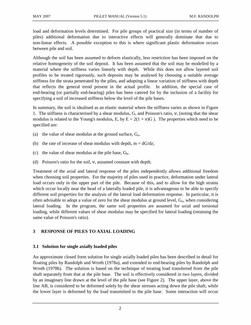
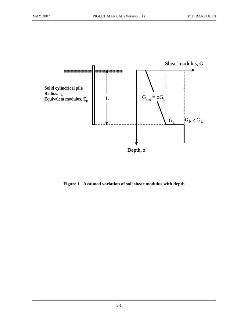
In summary, the soil is idealised as an elastic material where the stiffness varies as shown in Figure 1. The stiffness is characterised by a shear modulus, G, and Poisson's ratio, ν, (noting that the shear modulus is related to the Young's modulus, E, by E = 2(1 + ν)G ). The properties which need to be specified are:
(a) the value of shear modulus at the ground surface, Go.
(b) the rate of increase of shear modulus with depth, m = dG/dz;
(c) the value of shear modulus at the pile base, Gb.
(d) Poisson's ratio for the soil, ν, assumed constant with depth.
Treatment of the axial and lateral response of the piles independently allows additional freedom when choosing soil properties. For the majority of piles used in practice, deformation under lateral load occurs only in the upper part of the pile. Because of this, and to allow for the high strains which occur locally near the head of a laterally loaded pile, it is advantageous to be able to specify different soil properties for the analysis of the lateral load deformation response. In particular, it is often advisable to adopt a value of zero for the shear modulus at ground level, Go, when considering lateral loading. In the program, the same soil properties are assumed for axial and torsional loading, while different values of shear modulus may be specified for lateral loading (retaining the same value of Poisson's ratio).
3 RESPONSE OF PILES TO AXIAL LOADING
3.1 Solution for single axially loaded piles
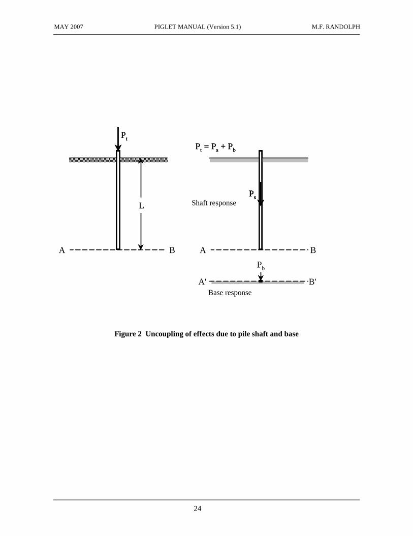
An approximate closed form solution for single axially loaded piles has been described in detail for floating piles by Randolph and Wroth (1978a), and extended to end-bearing piles by Randolph and Wroth (1978b). The solution is based on the technique of treating load transferred from the pile shaft separately from that at the pile base. The soil is effectively considered in two layers, divided by an imaginary line drawn at the level of the pile base (see Figure 2). The upper layer, above the line AB, is considered to be deformed solely by the shear stresses acting down the pile shaft, while the lower layer is deformed by the load transmitted to the pile base. Some interaction will occur
MAY 2007 PIGLET MANUAL (Version 5.1) M.F. RANDOLPH
3
between the upper and lower layers, which will serve to limit the radial extent of the deformation in the upper layer. To illustrate the method of analysis, the solution for a rigid pile will be developed here.
The load settlement ratio for the pile base is obtained directly from the Boussinesq solution as
ν−=
1
4
wrG
P
bbb
b (1)
where P is the load, w the settlement and r the pile radius, the subscript b referring to the pile base.
Turning to the pile shaft, considerations of vertical equilibrium entail that the shear stress, τ, at any depth falls off inversely with the radius, r, as (Cooke, 1974; Baguelin et al, 1975; Frank, 1974)
τ =τoro
r (2)
where the subscript o denotes conditions at the pile shaft. The shear strains, γ = τ /G, derived from this equation may be integrated to give the vertical deformation field, which will vary logarithmically with radius. In particular, if it is assumed that there is some radius, rm, at which the vertical deformations are effectively zero, then the settlement of the pile shaft may be written
ws = ζτoroG
(3)
where ζ = ln(rm/ro). Effectively, this equation is identical to that assumed in linear load transfer analysis, or a Winkler spring model for the soil response. In such a model, the load transferred from the pile at any depth is δP = 2πroτo, and the stiffness is given by
G2
w
Pk
s ζπ=δ= (4)
Equation (3) may be combined with equation (1) to give the overall load settlement ratio for a rigid pile of
( ) oto
t
r
L2
1
4
wrG
P
ζπρ+
ξν−η=
l
(5)
where η = rb/ro is the ratio of underream, ξ = GL/Gb is the ratio of end-bearing, and the subscript t denotes conditions at the top of the pile.
Development of the full solution, which takes account of compression of the pile is given in detail by Randolph and Wroth (1978a). Effectively, equation (3) is taken to act at each point down the length of the pile, just as in a linear load transfer analysis. The final expression for the load settlement ratio is
MAY 2007 PIGLET MANUAL (Version 5.1) M.F. RANDOLPH
4
( )
( )
( )( )
o
o
to
t
r
L
L
Ltanh
1
41
r
L
L
Ltanh2
1
4
wrG
P
µµ
ξν−πλη+
µµ
ζπρ+
ξν−η
=l
(6)
where, summarising the various dimensionless parameters:
η = rb/ro (ratio of underream for underreamed piles) ξ = GL/Gb (ratio of end-bearing for end-bearing piles) ρ = G /GL (variation of soil modulus with depth) λ = Ep/GL (pile-soil stiffness ratio) ζ = ln(rm/ro) (measure of radius of influence of pile) µL = 2 / ζλ (L/ro) (measure of pile compressibility).
It should be noted that Ep is the Young's modulus of a solid pile with equivalent cross-sectional rigidity to the actual pile. Thus Ep = (EA)p /(πro
2), where (EA)p is the actual cross-sectional rigidity of the pile. A suitable expression for the maximum radius of influence, rm, is
rm = 0.25 + ξ[2.5ρ(1 - ν) - 0.25]L (7)
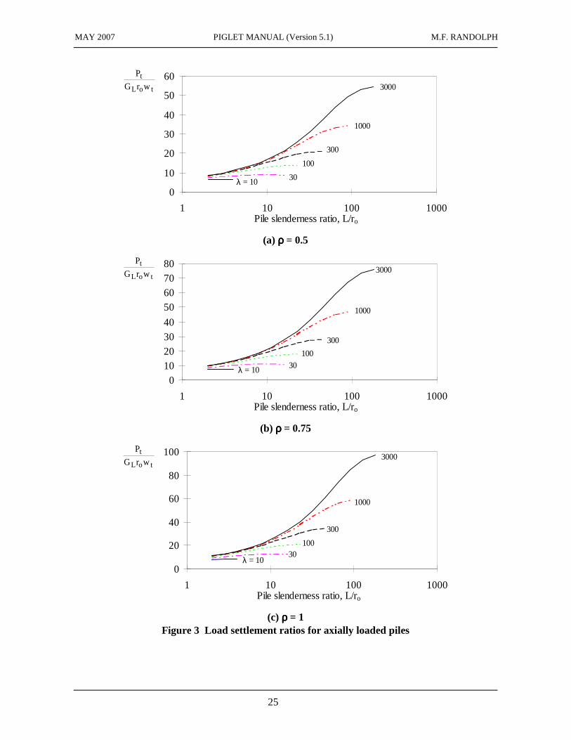
Figure 3 shows the variation of the load settlement ratio with slenderness ratio L/ro for η = ξ = 1, ν = 0.3. It has been found that these values are in reasonably good agreement with those computed using charts from Poulos and Davis (1980), in spite of the simplifying assumptions adopted in the analytical solution given above, and making allowance for the possible scope for error when using the various multiplicative factors taken from the charts in Poulos and Davis. For long compressible piles, the results from Poulos and Davis, which are based on boundary element analysis, give higher values of pile stiffness than obtained using equation (6). The higher values may be partly due to relatively coarse discretisation of the very long piles, leading to numerical inaccuracies.
From Figure 3, it may be seen that there are combinations of slenderness ratio, L/ro, and stiffness ratio, λ, beyond which the load settlement ratio becomes independent of the pile length. It can be shown that insignificant load is transmitted to the pile base for such long piles. This limiting behaviour is the converse of a stiff rigid pile, and corresponds to the case where the pile starts behaving as if it were infinitely long, with no load reaching the lower region.
The two limits may be quantified. Piles may be taken as essentially rigid where L/ro is less than 0.5(Ep/GL)0.5. Equation (6) then reduces to equation (5). At the other extreme, for piles where L/ro
is greater than about 3(Ep/GL)0.5, tanh(µL) approaches unity and equation (6) reduces approximately (exactly for ρ = 1) to
ζλπρ= /2wrG
P
toL
t (8)
As expected, the load settlement ratio is now independent of the length of the pile (since no load reaches the lower end). The modulus GL should be interpreted as the soil shear modulus at the bottom of the active part of the pile, that is, at a depth that corresponds to z/ro = 3(Ep/GL)0⋅5, rather
MAY 2007 PIGLET MANUAL (Version 5.1) M.F. RANDOLPH
5
than at z = L.
An alternative form of equation (6) for homogeneous soils has been presented by Mylonakis & Gazetas (1998), with the pile head stiffness, K = Pt/wt expressed as
( ) ( )( )Ltanh1
LtanhEAK p µΩ+
µ+Ωµ= (9)
The parameters Ω and µL represent non-dimensional base stiffness and slenderness ratio for the pile, expressed as
( ) ( ) LEA
kL and
EAw
P
ppb
b =µµ
=Ω (10)
where Pb and wb are respectively the load and displacement at the pile base and (EA)p is the cross-sectional rigidity of the pile.
3.2 Extension of solution to pile groups
For pile groups, the stiffness of each pile is reduced because of interaction effects. Mylonakis & Gazetas (1998) have demonstrated that the interaction factor, α, (as defined by Poulos, 1968) must reflect not only the (assumed) logarithmic decay in displacements, but also the reinforcing effect of the neighbouring pile. This leads to a reduction in the pile head displacement below that calculated from a logarithmic decay. For piles of the same length and diameter, the interaction factor for a given spacing, s, may then be expressed as the product of two terms representing the logarithmic decay and a ‘diffraction factor’, ξ (Mylonakis & Gazetas, 1998), giving:
( )( ) ξ
=α
om
m
r/rn
s/rn
l
l (11)
where the diffraction factor, ξ, is a function of Ω and µL, according to
( ) ( )[ ] ( )[ ]
( ) ( ) ( )L2cosh4L2sinh2L2sinh2
1L2cosh2L2L2sinhL2sinhL22
2
µΩ+µΩ+µ−µΩ+µ−µΩ+µ+µ=ξ (12)
Randolph (2003) has also extended this to deal with piles of different diameters.
The analysis presented by Mylonakis & Gazetas (1998) is for piles of identical embedded length. However, the general approach may also be used for piles of different length, provided interaction is first calculated for the effect on the shorter pile of loading the longer pile. The reverse interaction, where the shorter pile is loaded and causes displacement of the longer pile, may then be evaluated using the reciprocal theorem, to ensure a symmetric stiffness matrix. This extension for piles of different embedded lengths is only approximate, and results for groups where the pile
MAY 2007 PIGLET MANUAL (Version 5.1) M.F. RANDOLPH
6
lengths differ by more than a factor of about 4 should be viewed with circumspection.
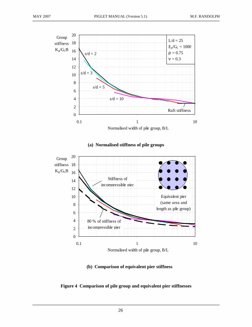
The above approach has been used to evaluate the stiffness of square groups of piles, from 2 x 2 up to 30 x 30, for L/d = 25, Ep/GL = 1000, ρ = 0.75 and ν = 0.3. The results are shown in Figure 4(a) where the pile group stiffness, Kg (ratio of total applied load to average settlement) has been normalized by GLB, where B is the width of the pile group. Plotting the normalized stiffness against the normalized width, B/L, leads to an envelope of curves that tends to the stiffness of a surface raft as B/L becomes large. The stiffness envelope may also be matched closely by using an equivalent pier approximation of the pile group (Poulos & Davis, 1980; Randolph, 1994), demonstrating the robustness of calculations of pile group stiffness even with quite approximate models (Figure 4(b)).
4 RESPONSE OF PILES TO TORSIONAL LOADING
The next type of loading to be considered is that of torsion about the pile axis. An analytical solution for the torsional response of piles has been presented by Randolph (1981b). Development of the solution follows the same lines as for the case of axially loaded piles, with the load transfer down the pile shaft being considered separately from that at the pile base.
At the pile base, the torque, T, may be related to the angle of twist, φ, using the established solution for the torsion of a rigid punch:
Tb
Gbrb3φb
=16
3 (13)
Down the pile shaft, it may be shown that the angle of twist is related to the interfacial shear stress, τo, by (Randolph, 1981b)
φ =τo2G
(14)
For rigid piles, the above two equations may be combined to give an overall torsional stiffness of
o
3
t3oL
t
r
L4
3
16
rG
Tπρ+
ξη=
φ (15)
where the parameters are as defined previously for axial loading.
In practice, few piles will behave as rigid piles under torsional loading. Usually, deformations induced by torsion reduce to negligible magnitude at some level down the pile shaft. The situation is then similar to that for most laterally loaded piles, with the pile length no longer affecting the performance of the pile. For piles of intermediate length, the torsional stiffness may be written
MAY 2007 PIGLET MANUAL (Version 5.1) M.F. RANDOLPH
7
( )
( )op
L3
o
3
t3oL
t
r
L
L
Ltanh
G
G
3
321
r
L
L
Ltanh4
3
16
rG
T
µµ
ξη
πρ+
µµπρ+
ξη
=φ
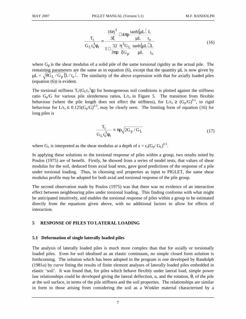
(16)
where Gp is the shear modulus of a solid pile of the same torsional rigidity as the actual pile. The remaining parameters are the same as in equation (6), except that the quantity µL is now given by µL = ( )opL r/LG/G8 . The similarity of the above expression with that for axially loaded piles (equation (6)) is evident.
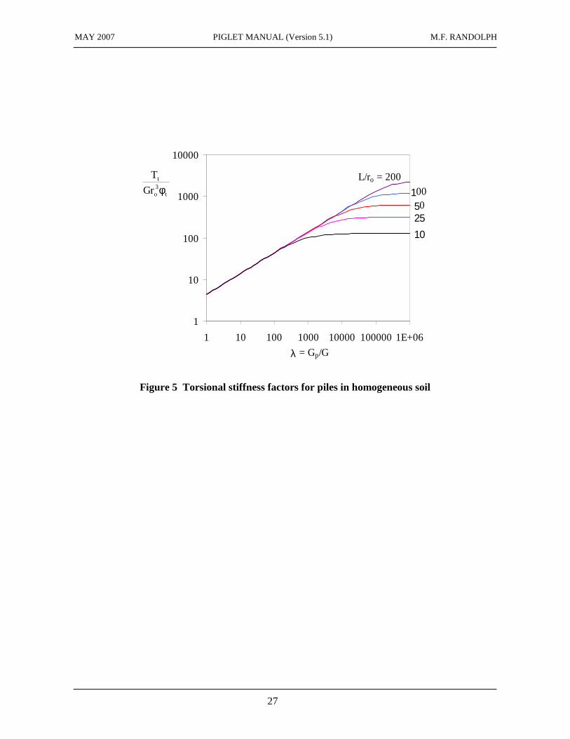
The torsional stiffness Tt/(GLro3φt) for homogeneous soil conditions is plotted against the stiffness
ratio Gp/G for various pile slenderness ratios, L/ro in Figure 5. The transition from flexible behaviour (where the pile length does not effect the stiffness), for L/ro ≥ (Gp/G)0.5, to rigid behaviour for L/ro ≤ 0.125(Gp/G)0.5, may be clearly seen. The limiting form of equation (16) for long piles is
Lpt
3oL
t G/G2rG
Tπρ=
φ (17)
where GL is interpreted as the shear modulus at a depth of z = ro(Gp/ GL)0.5.
In applying these solutions to the torsional response of piles within a group, two results noted by Poulos (1975) are of benefit. Firstly, he showed from a series of model tests, that values of shear modulus for the soil, deduced from axial load tests, gave good predictions of the response of a pile under torsional loading. Thus, in choosing soil properties as input to PIGLET, the same shear modulus profile may be adopted for both axial and torsional response of the pile group.
The second observation made by Poulos (1975) was that there was no evidence of an interaction effect between neighbouring piles under torsional loading. This finding conforms with what might be anticipated intuitively, and enables the torsional response of piles within a group to be estimated directly from the equations given above, with no additional factors to allow for effects of interaction.
5 RESPONSE OF PILES TO LATERAL LOADING
5.1 Deformation of single laterally loaded piles
The analysis of laterally loaded piles is much more complex than that for axially or torsionally loaded piles. Even for soil idealised as an elastic continuum, no simple closed form solution is forthcoming. The solution which has been adopted in the program is one developed by Randolph (1981a) by curve fitting the results of finite element analyses of laterally loaded piles embedded in elastic ‘soil’. It was found that, for piles which behave flexibly under lateral load, simple power law relationships could be developed giving the lateral deflection, u, and the rotation, θ, of the pile at the soil surface, in terms of the pile stiffness and the soil properties. The relationships are similar in form to those arising from considering the soil as a Winkler material characterised by a
MAY 2007 PIGLET MANUAL (Version 5.1) M.F. RANDOLPH
8
coefficient of subgrade reaction (e.g. Reese and Matlock, 1956; Matlock and Reese, 1960). As in the latter type of analysis, the concept of a ‘critical’ length of pile is used, this depth being the depth to which the pile deforms appreciably. The term ‘flexible’ is taken to refer to piles where the load deformation characteristics would not be altered by increasing the length of the pile. Thus piles that are longer than their critical length behave as ‘flexible’ piles. The large majority of piles used in practice fall into this category.
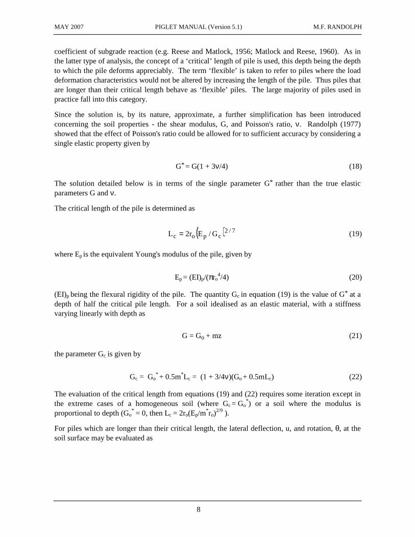
Since the solution is, by its nature, approximate, a further simplification has been introduced concerning the soil properties - the shear modulus, G, and Poisson's ratio, ν. Randolph (1977) showed that the effect of Poisson's ratio could be allowed for to sufficient accuracy by considering a single elastic property given by
G* = G(1 + 3ν/4) (18)
The solution detailed below is in terms of the single parameter G* rather than the true elastic parameters G and ν.
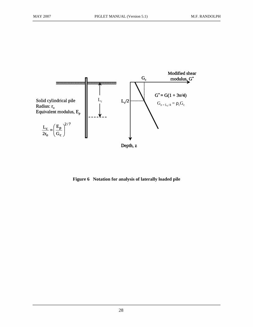
The critical length of the pile is determined as
( ) 7/2cpoc G/Er2L = (19)
where Ep is the equivalent Young's modulus of the pile, given by
Ep = (EI)p/(πro4/4) (20)
(EI)p being the flexural rigidity of the pile. The quantity Gc in equation (19) is the value of G* at a depth of half the critical pile length. For a soil idealised as an elastic material, with a stiffness varying linearly with depth as
G = Go + mz (21)
the parameter Gc is given by
Gc = Go*
+ 0.5m*Lc = (1 + 3/4ν)(Go + 0.5mLc) (22)
The evaluation of the critical length from equations (19) and (22) requires some iteration except in the extreme cases of a homogeneous soil (where Gc = Go
*) or a soil where the modulus is proportional to depth (Go
* = 0, then Lc = 2ro(Ep/m*ro)
2/9 ).
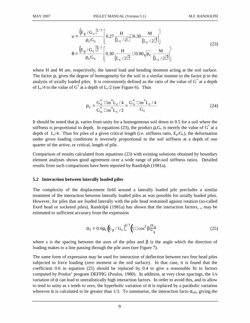
For piles which are longer than their critical length, the lateral deflection, u, and rotation, θ, at the soil surface may be evaluated as
MAY 2007 PIGLET MANUAL (Version 5.1) M.F. RANDOLPH
9
( )( ) ( )
( )( ) ( )
ρ+
ρ=θ
+
ρ=
3c
c2ccc
7/1cp
2cccc
7/1cp
2/L
M80.0
2/L
H30.0
G
G/E
2/L
M30.0
2/L
H27.0
G
G/Eu
(23)
where H and M are, respectively, the lateral load and bending moment acting at the soil surface. The factor ρc gives the degree of homogeneity for the soil in a similar manner to the factor ρ in the analysis of axially loaded piles. It is conveniently defined as the ratio of the value of G* at a depth of Lc/4 to the value of G* at a depth of Lc/2 (see Figure 6). Thus
c
c**
o
c**
o
c**
oc G
4/LmG
2/LmG
4/LmG +=
+
+=ρ (24)
It should be noted that ρc varies from unity for a homogeneous soil down to 0.5 for a soil where the stiffness is proportional to depth. In equations (23), the product ρcGc is merely the value of G* at a depth of Lc/4. Thus for piles of a given critical length (i.e. stiffness ratio, Ep/Gc), the deformation under given loading conditions is inversely proportional to the soil stiffness at a depth of one quarter of the active, or critical, length of pile.
Comparison of results calculated from equations (23) with existing solutions obtained by boundary element analyses shows good agreement over a wide range of pile-soil stiffness ratios. Detailed results from such comparisons have been reported by Randolph (1981a).
5.2 Interaction between laterally loaded piles
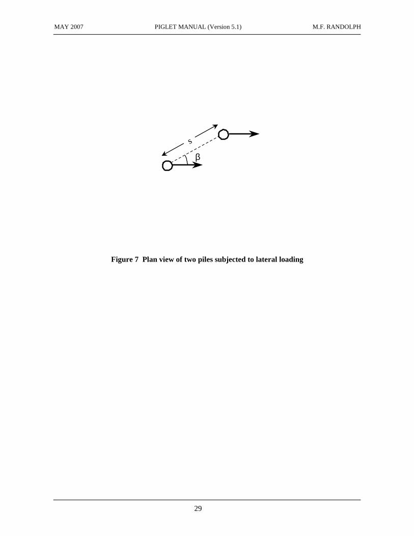
The complexity of the displacement field around a laterally loaded pile precludes a similar treatment of the interaction between laterally loaded piles as was possible for axially loaded piles. However, for piles that are loaded laterally with the pile head restrained against rotation (so-called fixed head or socketed piles), Randolph (1981a) has shown that the interaction factors, f, may be estimated to sufficient accuracy from the expression
αf = 0.6ρc Ep / Gc( )1/71+ cos2 β( )ro
s (25)
where s is the spacing between the axes of the piles and β is the angle which the direction of loading makes to a line passing through the pile axes (see Figure 7).
The same form of expression may be used for interaction of deflection between two free head piles subjected to force loading (zero moment at the soil surface). In that case, it is found that the coefficient 0.6 in equation (25) should be replaced by 0.4 to give a reasonable fit to factors computed by Poulos’ program DEFPIG (Poulos, 1980). In addition, at very close spacings, the 1/s variation of α can lead to unrealistically high interaction factors. In order to avoid this, and to allow to tend to unity as s tends to zero, the hyperbolic variation of α is replaced by a parabolic variation wherever α is calculated to be greater than 1/3. To summarise, the interaction facto αuH, giving the
MAY 2007 PIGLET MANUAL (Version 5.1) M.F. RANDOLPH
10
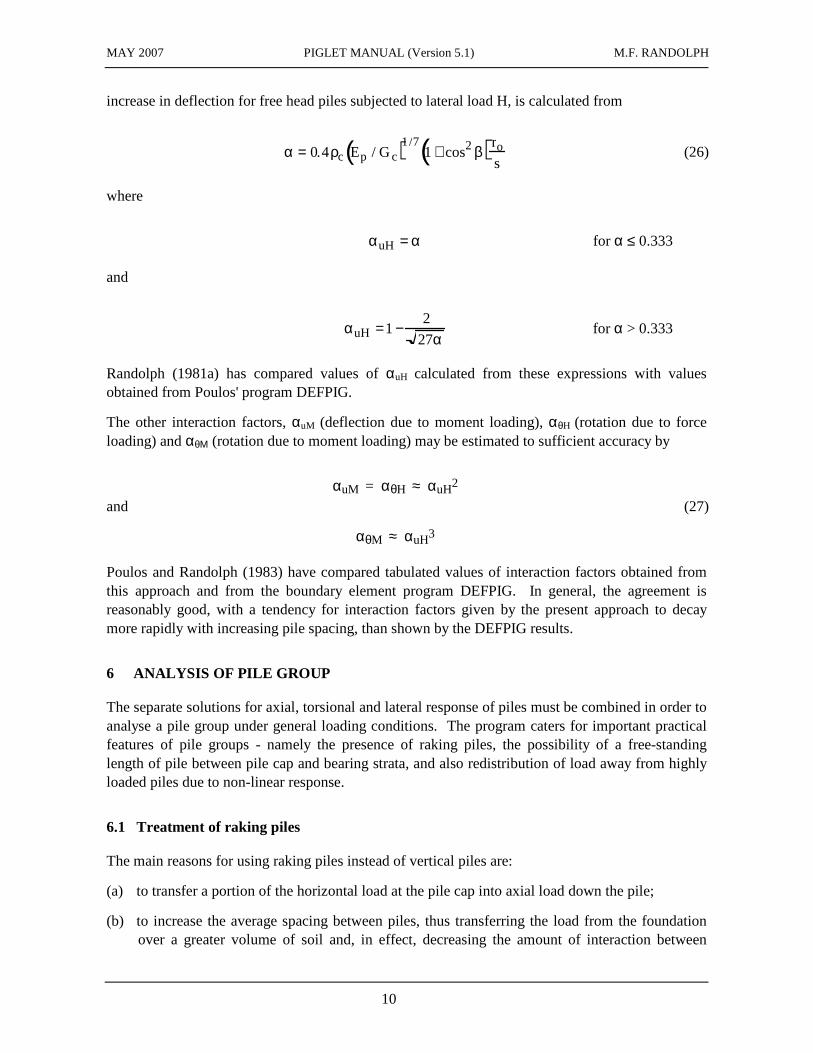
increase in deflection for free head piles subjected to lateral load H, is calculated from
α = 0.4ρc Ep / Gc( )1/71+ cos2 β( )ro
s (26)
where
αuH = α for α ≤ 0.333
and
αuH =1−2
27α for α > 0.333
Randolph (1981a) has compared values of αuH calculated from these expressions with values obtained from Poulos' program DEFPIG.
The other interaction factors, αuM (deflection due to moment loading), αθH (rotation due to force loading) and αθΜ (rotation due to moment loading) may be estimated to sufficient accuracy by
αuM = αθH ≈ αuH2
and (27)
αθM ≈ αuH3
Poulos and Randolph (1983) have compared tabulated values of interaction factors obtained from this approach and from the boundary element program DEFPIG. In general, the agreement is reasonably good, with a tendency for interaction factors given by the present approach to decay more rapidly with increasing pile spacing, than shown by the DEFPIG results.
6 ANALYSIS OF PILE GROUP
The separate solutions for axial, torsional and lateral response of piles must be combined in order to analyse a pile group under general loading conditions. The program caters for important practical features of pile groups - namely the presence of raking piles, the possibility of a free-standing length of pile between pile cap and bearing strata, and also redistribution of load away from highly loaded piles due to non-linear response.
6.1 Treatment of raking piles
The main reasons for using raking piles instead of vertical piles are:
(a) to transfer a portion of the horizontal load at the pile cap into axial load down the pile;
(b) to increase the average spacing between piles, thus transferring the load from the foundation over a greater volume of soil and, in effect, decreasing the amount of interaction between

MAY 2007 PIGLET MANUAL (Version 5.1) M.F. RANDOLPH
11
neighbouring piles.
The treatment of the first of these effects in the analysis is straightforward. The solutions outlined in the previous sections are used to calculate the stiffness matrices in terms of local pile axes (i.e. in terms of axial, torsional and lateral loads and deflections). When the overall group stiffness matrix is formed, the coordinate axes of each pile are transformed to global axes (vertical and horizontal). It should be noted that the bending moments induced in the piles by horizontal loading are relatively sensitive to the angle of rake of the piles. The use of raking piles instead of vertical piles for a particular foundation may well enable economies to be made in the choice of pile section. To balance this benefit of raking piles, the difficulties (and possible inaccuracies in positioning) in installing such piles must be borne in mind, as must the danger of using raking piles in circumstances where large vertical movements of piles or soil are possible. Fleming et al (1985) discuss this point in more detail.
Some discussion concerning reason (b) above is appropriate. Raking piles may be used to spread the foundation load over a greater volume of soil. The ability of the program to cope with piles raking in any direction (rather than in any one particular vertical plane) is an important one, since it enables the true spacing between pile centres to be calculated at a given depth. Consider, for example, a square 2 x 2 group of piles with L/ro = 40 and a pile spacing at ground level of s = 6ro. If the piles rake diagonally outwards at 1 in 8, the true average spacing down the shafts of the piles at adjacent corners is 11ro. If the analysis is restricted to piles raking in one direction only, the spacing between adjacent corner piles normal to this direction would remain at the surface spacing of 6ro.
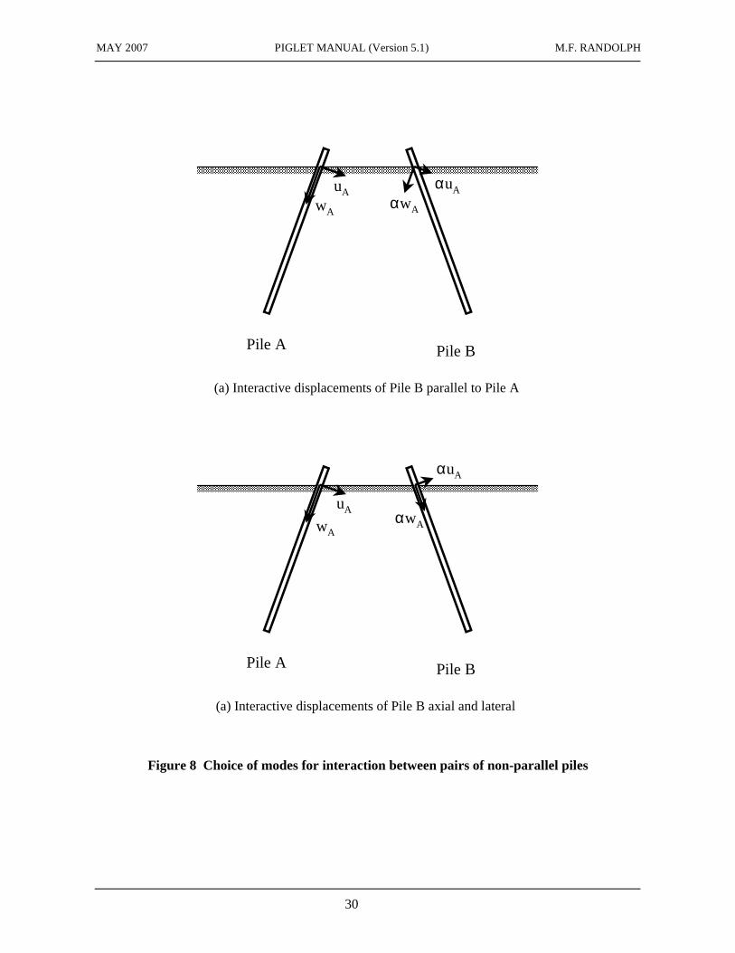
It is also necessary to consider the mode in which interaction is assumed to take place. For two piles which rake away from each other (see Figure 8), axial and lateral loading on pile A may be assumed to cause interactive displacement of pile B in mode (i) (Figure 8(b) - where the induced movements are parallel and normal to pile A) or in mode (ii) (Figure 8(c) - where the induced movements are parallel and normal to pile B). Poulos (1979) has discussed the merits of either choice in the analysis of pile groups with raking piles. He points out that the assumption of interaction in mode (ii) conforms with the reciprocal theorem of Betti, while that in mode (i) does not. Clearly both modes are idealisations of the real situation. However, in order to satisfy the reciprocal theorem, the second mode has been adopted in the present analysis. Adoption of this mode of interaction between piles has the additional advantage of enabling the axial load deformation behaviour of the piles to be considered independently from the lateral load deformation behaviour, before combining the two to obtain the overall deformation characteristics of the foundation.
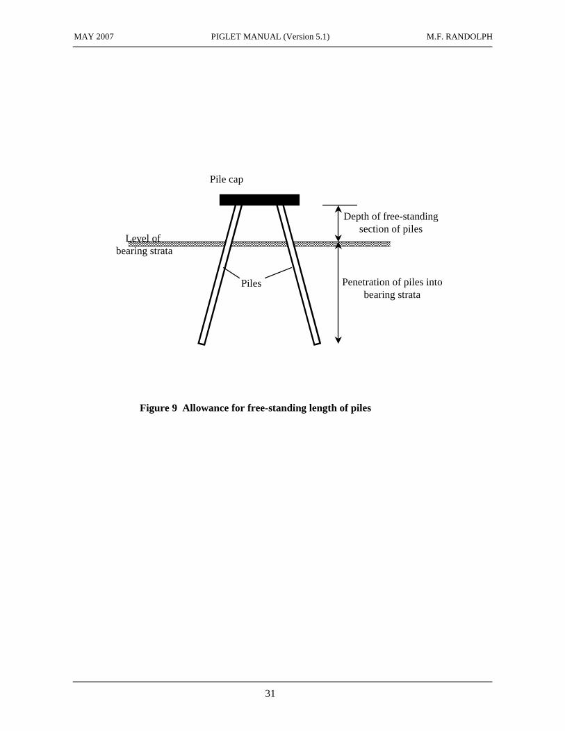
6.2 Allowance for free-standing length of piles
In many situations, the soil immediately below the pile cap may be relatively soft and should be ignored in the analysis of the load deformation characteristics of the pile group. In effect the pile cap is considered suspended above the top of the soil strata in which the piles are founded (see Figure 9). The resulting free-standing length of pile must be taken into account. This is achieved by modifying the axial, torsional and lateral flexibility matrices of the piles (which relate deformations and loads at the top of the bearing stratum), treating the free-standing section of pile as a simple cantilever. New flexibility matrices are formed relating the deformations and loads at the underside of the pile cap before combining these to give the required load deformation
MAY 2007 PIGLET MANUAL (Version 5.1) M.F. RANDOLPH
12
characteristics of the complete group. To allow for the situation where the upper part of a pile is cased as it passes through softer soil, it is possible in the program to specify different pile properties in the free-standing section than in the main part of the pile.
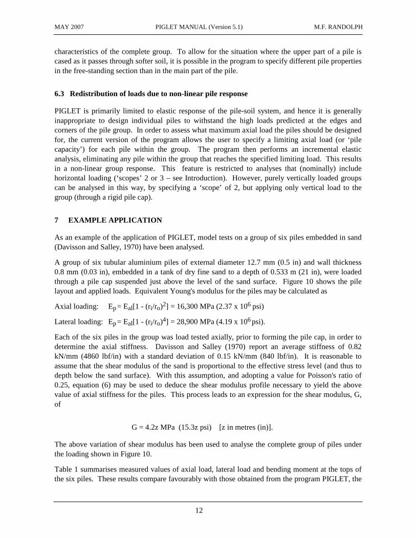
6.3 Redistribution of loads due to non-linear pile response
PIGLET is primarily limited to elastic response of the pile-soil system, and hence it is generally inappropriate to design individual piles to withstand the high loads predicted at the edges and corners of the pile group. In order to assess what maximum axial load the piles should be designed for, the current version of the program allows the user to specify a limiting axial load (or ‘pile capacity’) for each pile within the group. The program then performs an incremental elastic analysis, eliminating any pile within the group that reaches the specified limiting load. This results in a non-linear group response. This feature is restricted to analyses that (nominally) include horizontal loading (‘scopes’ 2 or 3 – see Introduction). However, purely vertically loaded groups can be analysed in this way, by specifying a ‘scope’ of 2, but applying only vertical load to the group (through a rigid pile cap).
7 EXAMPLE APPLICATION
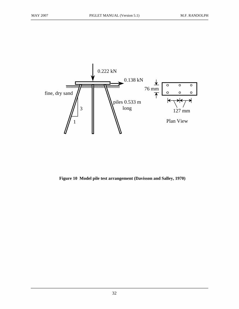
As an example of the application of PIGLET, model tests on a group of six piles embedded in sand (Davisson and Salley, 1970) have been analysed.
A group of six tubular aluminium piles of external diameter 12.7 mm (0.5 in) and wall thickness 0.8 mm (0.03 in), embedded in a tank of dry fine sand to a depth of 0.533 m (21 in), were loaded through a pile cap suspended just above the level of the sand surface. Figure 10 shows the pile layout and applied loads. Equivalent Young's modulus for the piles may be calculated as
Axial loading: Ep = Eal[1 - (ri/ro)2] = 16,300 MPa (2.37 x 10⁶ psi)
Lateral loading: Ep = Eal[1 - (ri/ro)4] = 28,900 MPa (4.19 x 10⁶ psi).
Each of the six piles in the group was load tested axially, prior to forming the pile cap, in order to determine the axial stiffness. Davisson and Salley (1970) report an average stiffness of 0.82 kN/mm (4860 lbf/in) with a standard deviation of 0.15 kN/mm (840 lbf/in). It is reasonable to assume that the shear modulus of the sand is proportional to the effective stress level (and thus to depth below the sand surface). With this assumption, and adopting a value for Poisson's ratio of 0.25, equation (6) may be used to deduce the shear modulus profile necessary to yield the above value of axial stiffness for the piles. This process leads to an expression for the shear modulus, G, of
G = 4.2z MPa (15.3z psi) [z in metres (in)].
The above variation of shear modulus has been used to analyse the complete group of piles under the loading shown in Figure 10.
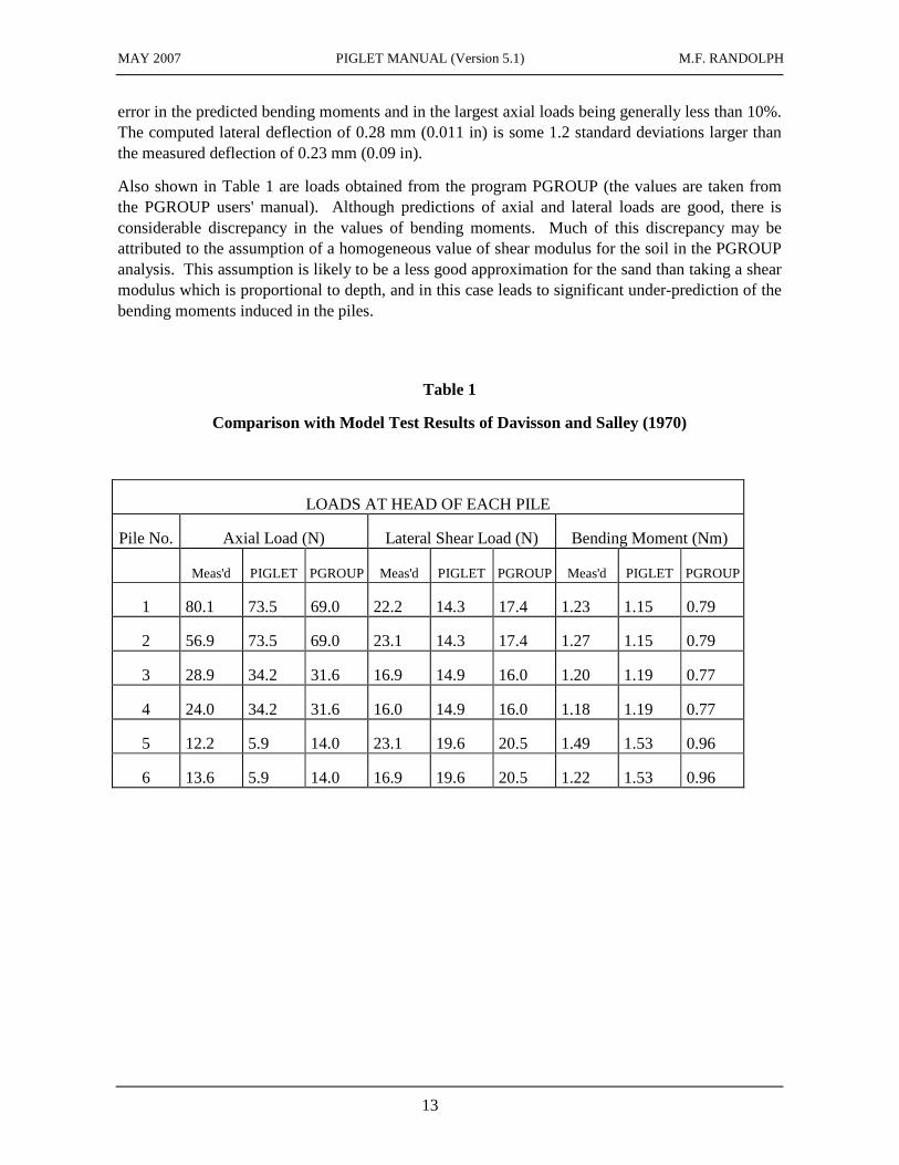
Table 1 summarises measured values of axial load, lateral load and bending moment at the tops of the six piles. These results compare favourably with those obtained from the program PIGLET, the
MAY 2007 PIGLET MANUAL (Version 5.1) M.F. RANDOLPH
13
error in the predicted bending moments and in the largest axial loads being generally less than 10%. The computed lateral deflection of 0.28 mm (0.011 in) is some 1.2 standard deviations larger than the measured deflection of 0.23 mm (0.09 in).
Also shown in Table 1 are loads obtained from the program PGROUP (the values are taken from the PGROUP users' manual). Although predictions of axial and lateral loads are good, there is considerable discrepancy in the values of bending moments. Much of this discrepancy may be attributed to the assumption of a homogeneous value of shear modulus for the soil in the PGROUP analysis. This assumption is likely to be a less good approximation for the sand than taking a shear modulus which is proportional to depth, and in this case leads to significant under-prediction of the bending moments induced in the piles.
Table 1
Comparison with Model Test Results of Davisson and Salley (1970)
LOADS AT HEAD OF EACH PILE
Pile No. Axial Load (N) Lateral Shear Load (N) Bending Moment (Nm)
Meas'd PIGLET PGROUP Meas'd PIGLET PGROUP Meas'd PIGLET PGROUP
1 80.1 73.5 69.0 22.2 14.3 17.4 1.23 1.15 0.79
2 56.9 73.5 69.0 23.1 14.3 17.4 1.27 1.15 0.79
3 28.9 34.2 31.6 16.9 14.9 16.0 1.20 1.19 0.77
4 24.0 34.2 31.6 16.0 14.9 16.0 1.18 1.19 0.77
5 12.2 5.9 14.0 23.1 19.6 20.5 1.49 1.53 0.96
6 13.6 5.9 14.0 16.9 19.6 20.5 1.22 1.53 0.96
MAY 2007 PIGLET MANUAL (Version 5.1) M.F. RANDOLPH
14
PART B: PROGRAM DOCUMENTATION
8 STRUCTURE OF PROGRAM
The program PIGLET has been structured so that the complexity, or ‘scope’, of analysis may be chosen by the user. The user may choose between three alternatives:
(1) analysis for vertical loading only (piles are assumed to be vertical);
(2) analysis for vertical and horizontal loading in one plane only (piles are assumed to be raked only in the plane of loading);
(3) full analysis of pile group under vertical, horizontal and torsional loading (piles may be raked in any direction).
The advantages of this choice are that the amount of input data, computer effort and output are all determined by the scope of the analysis, being a minimum for (1) and a maximum for (3). In addition, for vertical loading only, the program allows specification of a fully flexible cap, as opposed to the rigid cap assumed in the other options. As noted below, the latter two alternatives allow a non-linear response to be computed, by specifying limiting axial loads for each pile.
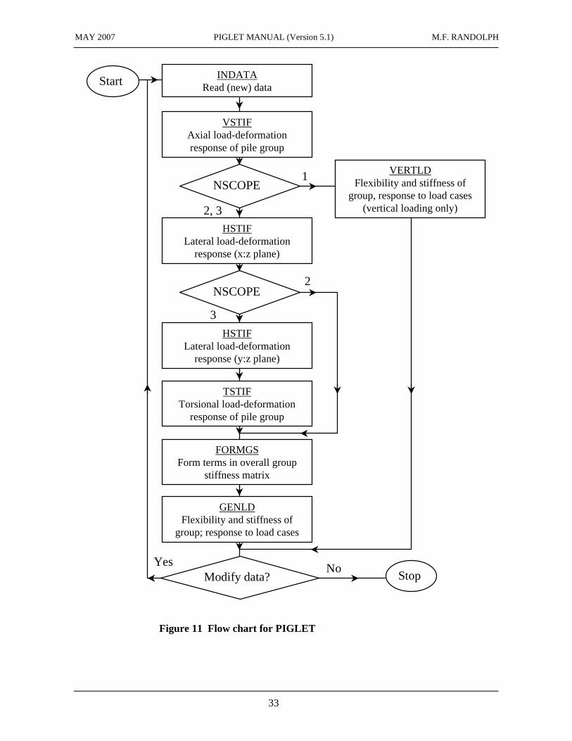
Data for the program is input on the ‘Data’ worksheet and the program is run by means either of the button on the spreadsheet, or by typing ‘Ctrl r’. A ‘Checksum’ comprising the sum of all input data items is output on the ‘Loadcases’ worksheet, and that value is checked before the program is run, to ensure that the data have changed since the previous analysis. A number of different loading cases may be considered in any given analysis. A flow chart for the program is shown in Figure 11. The only major branch point occurs for the case of vertical loading only (NSCOPE = 1), where the extra option of a fully flexible pile cap entails a different approach than for a rigid pile cap.
As supplied, the maximum problem size is set to 500 piles, which requires about 5 Mb of RAM to run. Alternative versions can be supplied that can analyse larger groups, at the cost of greater memory requirements. The program runs from an Excel workbook, where a macro calls a Fortran dynamic link library (DLL) in order to perform the analysis. In order for Excel to find the appropriate DLL, it is most convenient if a copy of the file is stored in the same directory as the workbook, and the workbook itself is opened by following the full ‘File’, ‘Open’ sequence within Excel, rather than taking any shortcuts (see the Readme worksheet within the workbook). Alternatively, the DLL can be stored in the system directory, which for the standard Windows operating system is C:\ Program Files\Microsoft Office\Office10.
9 PROGRAM INPUT
9.1 Data input and editing
Data input is on the worksheet ‘Data’ and is confined to the areas with yellow background. Standard Excel techniques, including formulae (for example, to give the coordinates of piles in large groups) may be used. It is important within the main pile geometry and loading array areas not to leave any gaps between successive entries.
MAY 2007 PIGLET MANUAL (Version 5.1) M.F. RANDOLPH
15
The description of each item of data is intended to be self-explanatory. However, additional notes are provided on the following pages to guide new users of the program. As in any engineering problem, a consistent set of units must be used in the input data. No system of units is assumed by the program. Essentially, the user must decide what unit of force (F) and what unit of length (L) are to be adopted. Data are then input in appropriate units according to the type of data. Thus values of modulus should be in units of F/L2, bending moments in FL, and so forth.
9.2 Data Items
Problem Title and Scope
The title may comprise any sequence of alphanumeric characters or punctuation marks. The ‘scope’ of the problem has been discussed in Section 8 of the manual. Essentially it defines the complexity of the applied loading, with options of (1) vertical loading only, (2) vertical and horizontal loading in one plane, or (3) full three-dimensional loading including torsion.
Pile Parameters
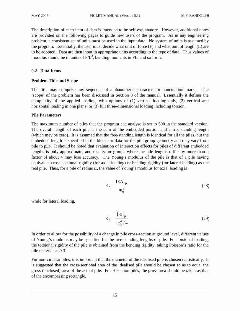
The maximum number of piles that the program can analyse is set to 500 in the standard version. The overall length of each pile is the sum of the embedded portion and a free-standing length (which may be zero). It is assumed that the free-standing length is identical for all the piles, but the embedded length is specified in the block for data for the pile group geometry and may vary from pile to pile. It should be noted that evaluation of interaction effects for piles of different embedded lengths is only approximate, and results for groups where the pile lengths differ by more than a factor of about 4 may lose accuracy. The Young’s modulus of the pile is that of a pile having equivalent cross-sectional rigidity (for axial loading) or bending rigidity (for lateral loading) as the real pile. Thus, for a pile of radius ro, the value of Young’s modulus for axial loading is
( )
2o
pp
r
EAE
π= (28)
while for lateral loading,
( )
4/r
EIE
4o
pp
π= (29)
In order to allow for the possibility of a change in pile cross-section at ground level, different values of Young’s modulus may be specified for the free-standing lengths of pile. For torsional loading, the torsional rigidity of the pile is obtained from the bending rigidity, taking Poisson’s ratio for the pile material as 0.3.
For non-circular piles, it is important that the diameter of the idealised pile is chosen realistically. It is suggested that the cross-sectional area of the idealised pile should be chosen so as to equal the gross (enclosed) area of the actual pile. For H section piles, the gross area should be taken as that of the encompassing rectangle.
MAY 2007 PIGLET MANUAL (Version 5.1) M.F. RANDOLPH
16
For lateral loading, there is a choice between whether the piles are to be assumed fixed into the pile cap or pinned to the pile cap (zero moment at pile cap level).
Note that, as described in Section 5.1, the kernel solution for lateral loading in PIGLET is only applicable to piles that are longer than (at least 80 % of) their critical length. A warning message will appear at the top of the output spreadsheets if that condition is violated.
Soil Parameters
The value of Poisson’s ratio for the soil is assumed the same for all types of loading - axial, lateral or torsional. Different profiles of shear modulus may be specified for axial and for lateral loading (the profile for torsional loading is assumed the same as for axial loading). As discussed in Section 2, the shear modulus profile is assumed to increase linearly with depth. The user specifies the value at the ground surface (which must be non-negative) and the gradient with depth (also non-negative). In addition, for vertical loading a sudden increase in modulus at the base of the pile (for end-bearing piles) may be input. If this value is set to less than the value that would be calculated from the linear variation of shear modulus, then the program corrects it to that value (thus the program does not permit any decrease in the value of shear modulus at the pile base).
For irregular soil profiles, it is important that the linear variation of soil modulus with depth is chosen so as to reflect the true average shear modulus over the depth of penetration of the piles, and also the trend of variation of soil modulus with depth. Since piles deflect under lateral loading only in the upper ten diameters or so, it is possible to specify different values of soil modulus for lateral loading than for axial (and torsional) loading.
In many instances, piles are installed so that they finish at some depth above a significantly stiffer stratum of soil. While such piles are not strictly 'end-bearing' piles, the stiffer stratum of soil will reduce the overall settlement of the group. For a stratum with shear modulus Gh, at a depth h (greater than the pile length L) it is recommended that the value of shear modulus below the pile bases, Gb, is chosen by means of the expression (Lee, 1991)
−
−+=
=
−=
Lz
L/h1
h
Lz
hb G
e1
G
G1
G
1
G
1 (30)
For values of h greater than 4L, the presence of the stiffer stratum of soil may be ignored.
For situations where no values of shear modulus are available for the soil, values of G must be chosen by inspection of the available soil data. For cohesive soil, it is common practice to correlate shear modulus with the shear strength su. At working load levels, the axial deformation of piles may be estimated reasonably well by taking shear modulus values in the range
200 ≤ G/su ≤ 400
Under lateral loading, the high strains which occur in the soil close to the pile give rise to lower secant modulus. It is suggested that G should be chosen in the range
MAY 2007 PIGLET MANUAL (Version 5.1) M.F. RANDOLPH
17
100 ≤ G/su ≤ 200
for the lateral load deformation behaviour of the pile group.
For non-cohesive soil, or where the only data available are results of standard penetration tests, it is suggested that the simple (but conservative) guideline of G = N MPa be adopted (see Randolph, 1981b). A less conservative correlation has been proposed by Wroth et al (1979), who suggest
G/pa ≈ 40N0.77 (28)
where pa is atmospheric pressure (100 kPa). In general, the variation of shear modulus with depth in sand (below the water table) may be expressed as G = mz, with m in the range 1 MPa/m (loose virgin sand) up to 5 MPa/m (dense sand).
In soft rocks, the effects of pile installation must be allowed for. While the in situ modulus of soft rocks such as chalk can be extremely high, installation of bored or driven piles tends to break up the block structure of the rock. The relevant shear modulus is then that associated with large strains (see Wakeling, 1970; Randolph and Wroth, 1978b).
Further guidance on the choice of shear modulus may be found in Wroth et al (1979). For pile groups under predominantly vertical load, Mandolini and Viggiani (1999)
Load Cases
Up to 20 separate load cases may be specified for each analysis. Loading may be specified explicitly (as forces and moments) or may be given as imposed deformations of the pile cap. The pile cap is assumed rigid accept for the case of vertical loading only, when arbitrary loads or deflections may be specified at the head of each pile.
The user is asked to specify a switch, for each load case, which identifies the loading type. For vertical loading only (Scope = 1), the switch values are:
Loading type 1: loads applied to a rigid pile cap
Loading type 2: deflections imposed on rigid pile cap
Loading type 3: loads applied to individual piles (fully flexible pile cap)
Loading type 4: deflections imposed on individual piles (fully flexible pile cap).
For the case of a fully flexible pile cap (loading types 3 and 4), the individual pile loads or deflections are specified for the corresponding load case in the Pile Group data block (see later).
For laterally loaded pile groups (Scope = 2 or 3), the corresponding switch values are:
Loading type 1: loads applied to a rigid pile cap
Loading type 2: deflections imposed on rigid pile cap
Loading type 3: vertical, horizontal and torsional loads applied to the rigid pile cap, but with zero rotation of the cap permitted (so-called ‘fixed-head’ condition); the fixing moments to ensure zero rotation are calculated by the program.
MAY 2007 PIGLET MANUAL (Version 5.1) M.F. RANDOLPH
18
These switches may be set to –1, -2 or –3 respectively, to indicate a non-linear analysis, with limiting axial loads specified for each such load case in the Pile Group data block (see later).
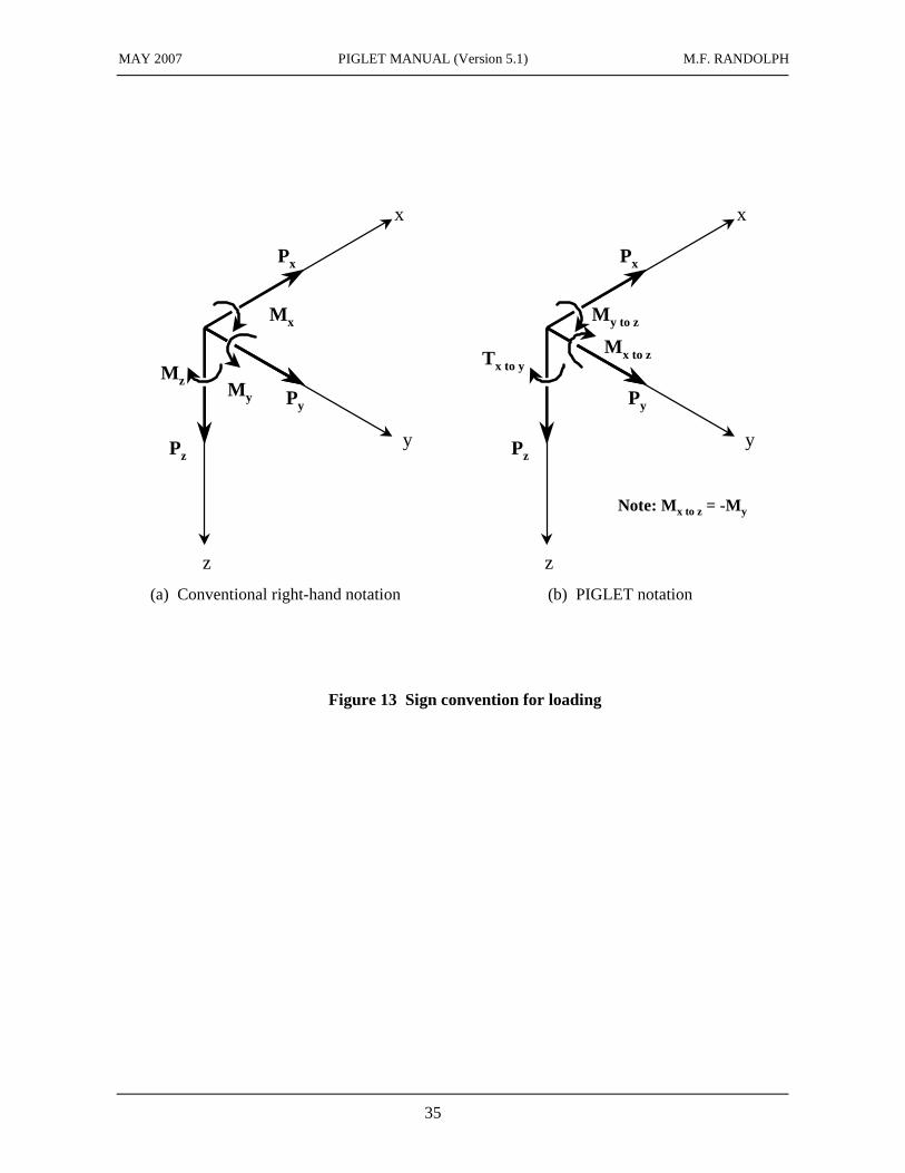
Where a rigid pile cap is specified (or assumed for problems involving horizontal loading), the total loads (or deflections) acting on the pile cap are specified, with all loads assumed to act at pile cap level (z = 0), through the origin (x = y = 0). Horizontal loads are taken as positive in the direction of the positive x and y axes, and moments are taken as positive in the sense of rotating the x axis towards the z axis (for loading in the x:z plane) and rotating the y axis towards the z axis (for loading in the y:z plane). This sign convention differs from the usual right-handed axis rule, as indicated in Figure 13.
Pile Group Geometry
For each pile, values of shaft diameter, base diameter, embedded length and (x, y) co-ordinates must be input. In addition, where lateral loading is involved, angles of rake must be specified in radians, either in the x:z plane (where loading is restricted to one plane only), or in both x:z and y:z planes.
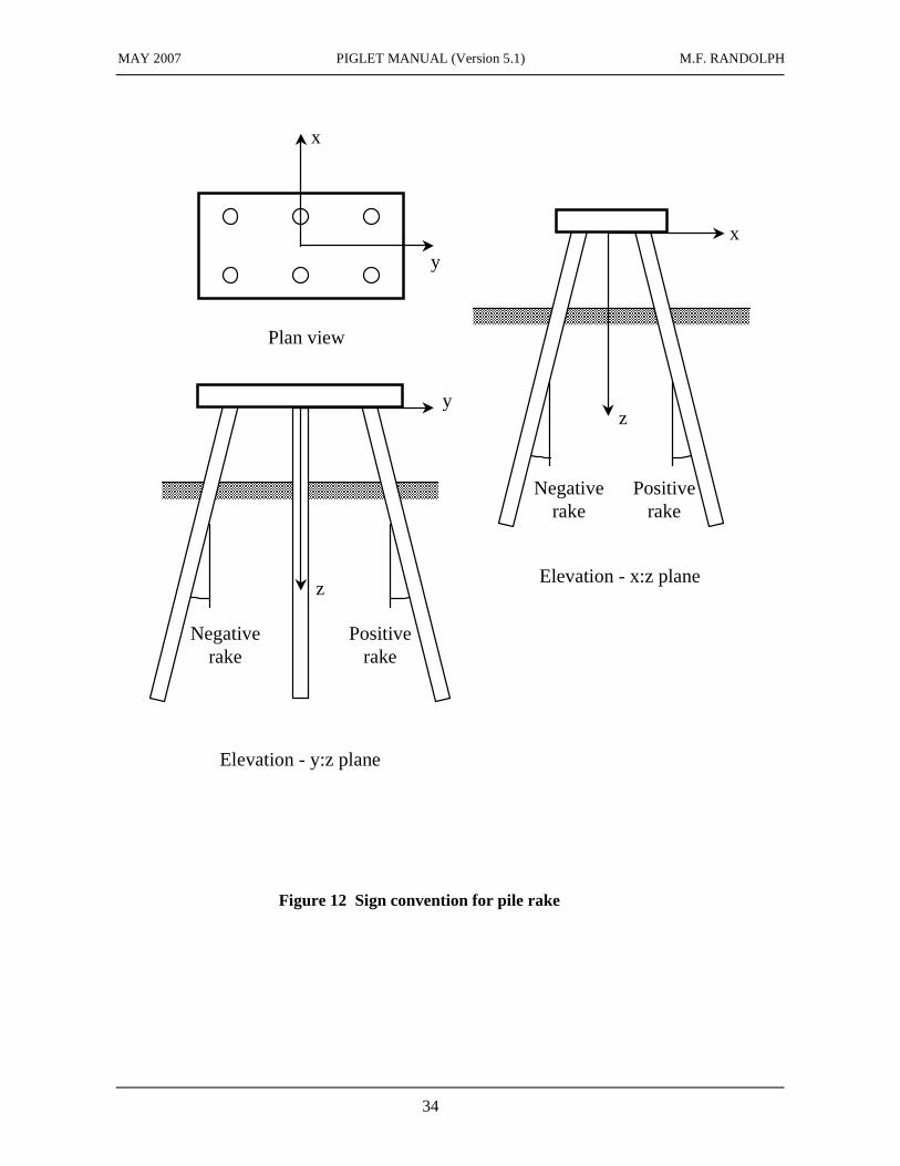
The program assumes a right-handed set of coordinate axes (x, y, z), with the z axis pointing vertically downwards. Angles of rake should be input in radians measured from the z axis, positive values indicating a pile lying between the x and z (or y and z) axes. Figure 12 shows this sign convention. The maximum angle of rake that is permitted is 1 radian.
Profiles of Bending Moment and Lateral Deflection
For analyses that involve lateral loading, profiles of bending moments and lateral deflection relative to the immediately surrounding soil may be output for specified piles. A switch is specified for each pile as to whether (a) no profiles (switch zero or blank), (b) profiles of bending moment only (switch = 1), or (c) profiles of bending moment and lateral deflection (switch = 2), are required. For three-dimensional loading, separate choices are given for the x:z plane and the y:z plane.
It should be emphasised that, since the free field soil deflections (due to interaction between piles) are not included in the relative lateral deflection profile, the deflection output for the pile head will not correspond with the total lateral deflection for the pile head (except for analyses with only one pile in the group).
Pile Group Loads (Deflections) or Limiting Loads
For vertical loading through a fully flexible pile cap (Scope = 1, Loading Type = 2 or 4), the loads or deflections applied to each pile are specified for the corresponding load case to the right of the pile group geometry. For problems involving lateral loading (Scope = 2 or 3), and negative loading types, the limiting axial loads for each pile are specified for the corresponding load case to the right of the pile group geometry.
10 PROGRAM OUTPUT
Output from the program is provided on three separate worksheets, ‘Outputparameters’, ‘Loadcases’ and ‘Summary’. The first of these provides a brief summary of the problem to be analysed and then key solutions parameters for the different deformation modes, followed by:
MAY 2007 PIGLET MANUAL (Version 5.1) M.F. RANDOLPH
19
(1) Response of pile group to unit deformations of the pile cap, giving loads and moments at the head of each pile, in local coordinates.
(2) Overall stiffness and flexibility matrices for the group.
The second output sheet (‘Loadcases’) then gives the response of the pile group to the different load cases specified by the user. This section includes loads and resulting deformations of the pile cap, loads and moments at the head of each pile, and (optionally) profiles of bending moment and lateral deflection down specified piles.
Finally, where more than a single load case is analysed, summary tables are included on the third output worksheet (‘Summary’), where the loads and deflections at the head of each pile are summarised for each load case.
The sign convention for lateral loads and moments for each pile follows that for specifying the applied loads, with lateral load being taken as positive in the direction of the positive x and y axes, and moments taken as positive in the sense of rotating the x axis towards the z axis (for loading in the x:z plane) and rotating the y axis towards the z axis (for loading in the y:z plane).
11 REFERENCES
1. Baguelin F., Bustamante M., Frank R. and Jezequel J.F. (1975). La capacite portante des pieux. Annales de l'Institut Technique du Batiment et des Travaux Publics, Suppl. 330, Serie SF116, pp 1-22.
2. Banerjee P.K. and Davies T.G. (1978). The behaviour of axially and laterally loaded piles embedded in non-homogeneous soils. Géotechnique, 28(3), 309-326.
3. Banerjee P.K., Driscoll R.M.C. and Davies T. (1978). Program For The Analysis Of Pile Groups Of Any Geometry Subjected To Horizontal And Vertical Loads And Moments, Pgroup, (3.0). HECB/B/7, Department of Transport, HECB, London.
4. Butterfield R. and Douglas R.A. (1981). Flexibility coefficients for the design of piles and pile groups. CIRIA Technical Note 108.
5. Cooke R.W. (1974). Settlement of friction pile foundations. Proc. Conf. on Tall Buildings, Kuala Lumpur, 7-19.
6. Davisson M.T. and Salley J.R. (1970). Model study of laterally loaded piles. J. of Soil Mech. and Found. Engg Div., ASCE, 96(SM5).
7. Fleming W.G.K., Weltman A.J., Randolph M.F. and Elson W.K. (1985). Piling Engineering. Surrey University Press, Glasgow.
8. Frank R. (1974). Etude Theorique Du Comportement Des Pieux Sous Charge Verticale; Introduction De La Dilatance. Dr-Eng. Thesis, University Paris VI (Pierre et Marie Curie University).
9. Lee C.Y. (1991). Discrete layer analysis of axially loaded piles and pile groups. Computers and Geotechnics, 11, 295-313.
MAY 2007 PIGLET MANUAL (Version 5.1) M.F. RANDOLPH
20
10. Mandolini, A. & Viggiani, C. (1997). Settlement of piled foundations. Géotechnique, 47(4), 791-816.
11. Matlock H. and Reese L.C. (1960). Generalised solutions for laterally loaded piles. J. Soil Mech. and Found. Engng Div., ASCE, 86(SM5).
12. Mylonakis, G. & Gazetas, G. (1998). Settlement and additional internal forces of grouped piles in layered soil. Géotechnique, 48(1), 55-72.
13. O'Neill M.W., Ghazzaly O.I. and Ha H.B. (1977). Analysis of three-dimensional pile groups with non-linear soil response and pile-soil pile interaction. Proc. 9th Offshore Technology Conf., 2, 245-256.
14. Poulos H.G. (1971). Behaviour of laterally loaded piles, I - Single piles, II - Pile groups. J. Soil Mech and Found. Engng Div., ASCE, 97(SM5).
15. Poulos H.G. (1973). Load-deflection prediction for laterally loaded piles. Australian Geomechanics Journal, 3(1).
16. Poulos H.G. (1975). Torsional response of piles. J. Geot. Engng Div., ASCE, 101(GT10).
17. Poulos H.G. (1979). An approach for the analysis of offshore pile groups. Proc. Conf. on Numerical Methods in Offshore Piling, ICE, London, 119-126.
18. Poulos H.G. (1979). Settlement of single piles in non-homogeneous soil. J. Geot. Engng Div., ASCE, 105(GT5).
19. Poulos H.G. (1980). Users' Guide To Program DEFPIG - Deformation Analysis Of Pile Groups. School of Civil Engineering, University of Sydney.
20. Poulos H.G. and Davis E.H. (1980). Pile foundation analysis and design. John Wiley & Sons, New York.
21. Poulos H.G. and Randolph M.F. (1983). Pile group analysis: a study of two methods. J. of Geot. Eng., ASCE, 109(3), 355-372.
22. Randolph M.F. (1977). A Theoretical Study Of The Performance Of Piles. PhD Thesis, University of Cambridge.
23. Randolph M.F. (1981). Analysis of the behaviour of piles subjected to torsion. J. of Geot. Engng Div., ASCE, 107(GT8), 1095-1111.
24. Randolph M.F. (1981). The response of flexible piles to lateral loading. Géotechnique, 31(2), 247-259.
25. Randolph, M.F. (2003). Science and empiricism in pile foundation design: 43rd Rankine Lecture, Géotechnique, 53 (in press).
26. Randolph M.F. and Wroth C.P. (1978). Analysis of deformation of vertically loaded piles. J. of the Geot. Eng. Div., ASCE, 104(GT12), 1465-1488.
27. Randolph M.F. and Wroth C.P. (1978). A simple approach to pile design and the analysis of pile tests. Proc. Symp. on Behaviour of Deep Foundations, ASTM STP 470, 484-499.
MAY 2007 PIGLET MANUAL (Version 5.1) M.F. RANDOLPH
21
28. Randolph M.F. and Wroth C.P. (1979). An analysis of the vertical deformation of pile groups. Géotechnique, 29(4), 423-439.
29. Reese L.C. and Matlock H. (1956). Non-dimensional solutions for laterally loaded piles. Proc. 8th Texas Conf. on Soil Mech.
30. Wakeling T.R.M. (1970). A comparison of the results of standard site investigation methods against the results of a detailed geotechnical investigation in Middle Chalk at Mundford, Norfolk. Proc. Conf. on In Situ Investigations in Soils and Rocks, British Geotechnical Society, London.
31. Wroth C.P., Randolph M.F., Houlsby G.T. and Fahey M. (1979). A review of the engineering properties of soils with particular reference to the shear modulus. Cambridge University Engineering Department Research Report, CUED/D - Soils TR 75.
MAY 2007 PIGLET MANUAL (Version 5.1) M.F. RANDOLPH
22
FIGURE TITLES
Figure 1 Assumed variation of soil shear modulus with depth
Figure 2 Uncoupling of effects due to pile shaft and base
Figure 3 Load settlement ratios for compressible piles
Figure 4 Comparison of pile group and equivalent pier stiffnesses
Figure 5 Torsional stiffness factor for piles in homogeneous soil
Figure 6 Notation for analysis of laterally loaded piles
Figure 7 Plan view of two piles subjected to lateral loading
Figure 8 Choice of modes for interaction between pairs of non-parallel piles
Figure 9 Allowance for free-standing length of piles
Figure 10 Model pile test arrangement (Davisson and Salley, 1970)
Figure 11 Flow chart for PIGLET
Figure 12 Sign convention for pile rake
Figure 13 Sign convention for loading
MAY 2007 PIGLET MANUAL (Version 5.1) M.F. RANDOLPH
23
Shear modulus, G
Depth, z
GL
Gavg = ρGLL
Solid cylindrical pileRadius: roEquivalent modulus, Ep
Lb GG ≥
Shear modulus, G
Depth, z
GL
Gavg = ρGLL
Solid cylindrical pileRadius: roEquivalent modulus, Ep L
Solid cylindrical pileRadius: roEquivalent modulus, Ep
Lb GG ≥
Figure 1 Assumed variation of soil shear modulus with depth
MAY 2007 PIGLET MANUAL (Version 5.1) M.F. RANDOLPH
24
Figure 2 Uncoupling of effects due to pile shaft and base
B
L
A B
A' B'
Pt
Pt = Ps + Pb
A
Pb
PsShaft response
Base response
B
L
A B
L
A B
A' B'
Pt
Pt = Ps + Pb
A
Pb
PsShaft response
Base response
A
Pb
PsShaft response
Base response
MAY 2007 PIGLET MANUAL (Version 5.1) M.F. RANDOLPH
25
0
10
20
30
40
50
60
1 10 100 1000Pile slenderness ratio, L/ro
λ = 10 30
100
300
3000
1000
toL
t
wrG
P
(a) ρρρρ = 0.5
010203040
50607080
1 10 100 1000Pile slenderness ratio, L/ro
λ = 10 30100
300
3000
1000
toL
t
wrG
P
(b) ρρρρ = 0.75
0
20
40
60
80
100
1 10 100 1000Pile slenderness ratio, L/ro
λ = 1030
100
300
3000
1000
toL
t
wrG
P
(c) ρρρρ = 1
Figure 3 Load settlement ratios for axially loaded piles
MAY 2007 PIGLET MANUAL (Version 5.1) M.F. RANDOLPH
26
0
2
4
6
8
10
12
14
16
18
20
0.1 1 10
Normalised width of pile group, B/L
Group
stiffness
Kg/GLB
L/d = 25
Ep/GL = 1000
ρ = 0.75
ν = 0.3s/d = 2
s/d = 3
s/d = 5
s/d = 10
Raft stiffness
(a) Normalised stiffness of pile groups
0
2
4
6
8
10
12
14
16
18
20
0.1 1 10
Normalised width of pile group, B/L
Group
stiffness
Kg/GLB
Equivalent pier
(same area and
length as pile group)
Stiffness of
incompressible pier
80 % of stiffness of
incompressible pier
(b) Comparison of equivalent pier stiffness
Figure 4 Comparison of pile group and equivalent pier stiffnesses
MAY 2007 PIGLET MANUAL (Version 5.1) M.F. RANDOLPH
27
1
10
100
1000
10000
1 10 100 1000 10000 100000 1E+06
λ = Gp/G
t3o
t
Gr
T
φL/ro = 200
100
502510
Figure 5 Torsional stiffness factors for piles in homogeneous soil
MAY 2007 PIGLET MANUAL (Version 5.1) M.F. RANDOLPH
28
Figure 6 Notation for analysis of laterally loaded pile
LcSolid cylindrical pileRadius: roEquivalent modulus, Ep
Modified shear modulus, G*
Depth, z
Gc
Gz = L /4 = ρcGcLc/2
c
G* = G(1 + 3ν/4)
7/2
c
p
o
c
G
E
r2
L
=
LcSolid cylindrical pileRadius: roEquivalent modulus, Ep
Modified shear modulus, G*
Depth, z
Gc
Gz = L /4 = ρcGcLc/2
c
G* = G(1 + 3ν/4)
Modified shear modulus, G*
Depth, z
Gc
Gz = L /4 = ρcGcLc/2
c
G* = G(1 + 3ν/4)
7/2
c
p
o
c
G
E
r2
L
=
MAY 2007 PIGLET MANUAL (Version 5.1) M.F. RANDOLPH
29
Figure 7 Plan view of two piles subjected to lateral loading
s
β
MAY 2007 PIGLET MANUAL (Version 5.1) M.F. RANDOLPH
30
(a) Interactive displacements of Pile B parallel to Pile A
Figure 8 Choice of modes for interaction between pairs of non-parallel piles
Pile A Pile B
(a) Interactive displacements of Pile B axial and lateral
Pile A Pile B
wA
uAαwA
αuA
wA
uA αwA
αuA
MAY 2007 PIGLET MANUAL (Version 5.1) M.F. RANDOLPH
31
Figure 9 Allowance for free-standing length of piles
Pile cap
Piles
Level of bearing strata
Depth of free-standingsection of piles
Penetration of piles intobearing strata
MAY 2007 PIGLET MANUAL (Version 5.1) M.F. RANDOLPH
32
Figure 10 Model pile test arrangement (Davisson and Salley, 1970)
3
1
fine, dry sand
0.222 kN
0.138 kN
piles 0.533 mlong
76 mm
127 mm
Plan View
MAY 2007 PIGLET MANUAL (Version 5.1) M.F. RANDOLPH
33
Figure 11 Flow chart for PIGLET
VSTIFAxial load-deformationresponse of pile group
HSTIFLateral load-deformation
response (x:z plane)
HSTIFLateral load-deformation
response (y:z plane)
TSTIFTorsional load-deformation
response of pile group
FORMGSForm terms in overall group
stiffness matrix
GENLDFlexibility and stiffness of
group; response to load cases
VERTLDFlexibility and stiffness of
group, response to load cases(vertical loading only)
INDATARead (new) data
NSCOPE
NSCOPE
Modify data?
Start
Stop
1
2, 3
2
3
NoYes
MAY 2007 PIGLET MANUAL (Version 5.1) M.F. RANDOLPH
34
x
y
y
z
z
x
Plan view
Elevation - x:z plane
Elevation - y:z plane
Negativerake
Negativerake
Positiverake
Positiverake
Figure 12 Sign convention for pile rake
MAY 2007 PIGLET MANUAL (Version 5.1) M.F. RANDOLPH
35
x
y
z
Px
Py
Pz
My
Mz
Mx
x
y
z
Px
Py
Pz
Mx to zTx to y
My to z
(a) Conventional right-hand notation (b) PIGLET notation
Figure 13 Sign convention for loading
Note: Mx to z = -My