PicoScope 3000 Series - Farnell element14 · The PicoScope 3000 Series oscilloscopes are also...
28
USB oscilloscopes PicoScope ® 3000 Series www.picotech.com 60 to 250 MHz analog bandwidth Up to 1 GS/s real-time sampling 2 or 4 analog channels MSO models with 16 digital channels Built-in function generator and AWG Up to 512 MS buffer memory Hardware-accelerated update rates USB connected and powered Automatic measurements Mask limit testing Advanced triggers Serial decoding Math channels Spectrum analyzer Free technical support and updates Free SDK and example programs 5 year warrranty included
Transcript of PicoScope 3000 Series - Farnell element14 · The PicoScope 3000 Series oscilloscopes are also...

USB oscilloscopes
PicoScope® 3000 Series
www.picotech.com
60 to 250 MHz analog bandwidthUp to 1 GS/s real-time sampling
2 or 4 analog channelsMSO models with 16 digital channelsBuilt-in function generator and AWG
Up to 512 MS buffer memoryHardware-accelerated update rates
USB connected and powered
Automatic measurementsMask limit testing
Advanced triggersSerial decodingMath channels
Spectrum analyzer
Free technical support and updatesFree SDK and example programs
5 year warrranty included
PicoScope 3000 Series
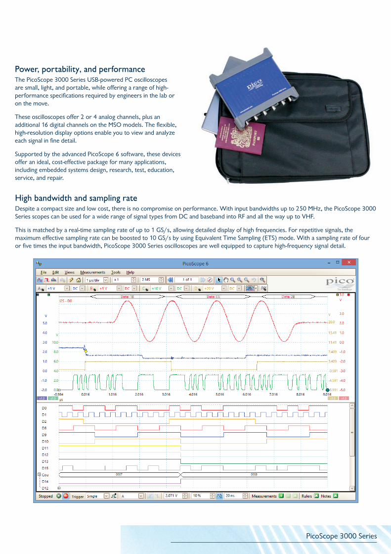
Power, portability, and performanceThe PicoScope 3000 Series USB-powered PC oscilloscopes are small, light, and portable, while offering a range of high-performance specifications required by engineers in the lab or on the move.
These oscilloscopes offer 2 or 4 analog channels, plus an additional 16 digital channels on the MSO models. The flexible, high-resolution display options enable you to view and analyze each signal in fine detail.
Supported by the advanced PicoScope 6 software, these devices offer an ideal, cost-effective package for many applications, including embedded systems design, research, test, education, service, and repair.
High bandwidth and sampling rateDespite a compact size and low cost, there is no compromise on performance. With input bandwidths up to 250 MHz, the PicoScope 3000 Series scopes can be used for a wide range of signal types from DC and baseband into RF and all the way up to VHF.
This is matched by a real-time sampling rate of up to 1 GS/s, allowing detailed display of high frequencies. For repetitive signals, the maximum effective sampling rate can be boosted to 10 GS/s by using Equivalent Time Sampling (ETS) mode. With a sampling rate of four or five times the input bandwidth, PicoScope 3000 Series oscilloscopes are well equipped to capture high-frequency signal detail.

PicoScope 3000 Series
Deep memoryThe PicoScope 3000 Series oscilloscopes are also market leaders in offering a huge buffer memory, allowing them to sustain their high sampling rates across long timebases. For example, using a 512 MS buffer the PicoScope 3207B can sample at 1 GS/s all the way down to 50 ms/div (a 500 ms total capture time).
Powerful tools are included to allow you to manage and examine all of this data. As well as functions such as mask limit testing and color persistence mode, the PicoScope 6 software enables you to zoom into your waveform by several million times. A zoom overview window allows you to easily control the size and location of the zoom area.
Up to 10 000 waveforms can be stored in the segmented waveform buffer. The Buffer Overview window then allows you to rewind and review the history of your waveform. No longer will you struggle to catch an infrequent glitch.
x2 000 000x130 000
x256x1

PicoScope 3000 Series
PicoScope 3000 Series oscilloscopes - overview
PicoScope model
USB 2.0
USB 3.0
AWG* BandwidthBuffer
memory
Max. sampling
rate
3204D MSO • • 60 MHz 128 MS 1 GS/s
3205D MSO • • 100 MHz 256 MS 1 GS/s
3206D MSO • • 200 MHz 512 MS 1 GS/s
3404D MSO • • 60 MHz 128 MS 1 GS/s
3405D MSO • • 100 MHz 256 MS 1 GS/s
3406D MSO • • 200 MHz 512 MS 1 GS/s
PicoScope model
USB 2.0
USB 3.0
AWG* BandwidthBuffer
memory
Max. sampling
rate
3404A • 60 MHz 4 MS 1 GS/s
3404B • • 60 MHz 8 MS 1 GS/s
3405A • 100 MHz 16 MS 1 GS/s
3405B • • 100 MHz 32 MS 1 GS/s
3406A • 200 MHz 64 MS 1 GS/s
3406B • • 200 MHz 128 MS 1 GS/s
PicoScope model
USB 2.0
USB 3.0
AWG* BandwidthBuffer
memory
Max. sampling
rate
3204A • 60 MHz 4 MS 500 MS/s
3204B • • 60 MHz 8 MS 500 MS/s
3205A • 100 MHz 16 MS 500 MS/s
3205B • • 100 MHz 32 MS 500 MS/s
3206A • 200 MHz 64 MS 500 MS/s
3206B • • 200 MHz 128 MS 500 MS/s
3207A • 250 MHz 256 MS 1 GS/s
3207B • • 250 MHz 512 MS 1 GS/s
* Arbitrary waveform generator
2 analog channels
4 analog channels
2 / 4 analog channels16 digital channels
PicoScope 3000 Series
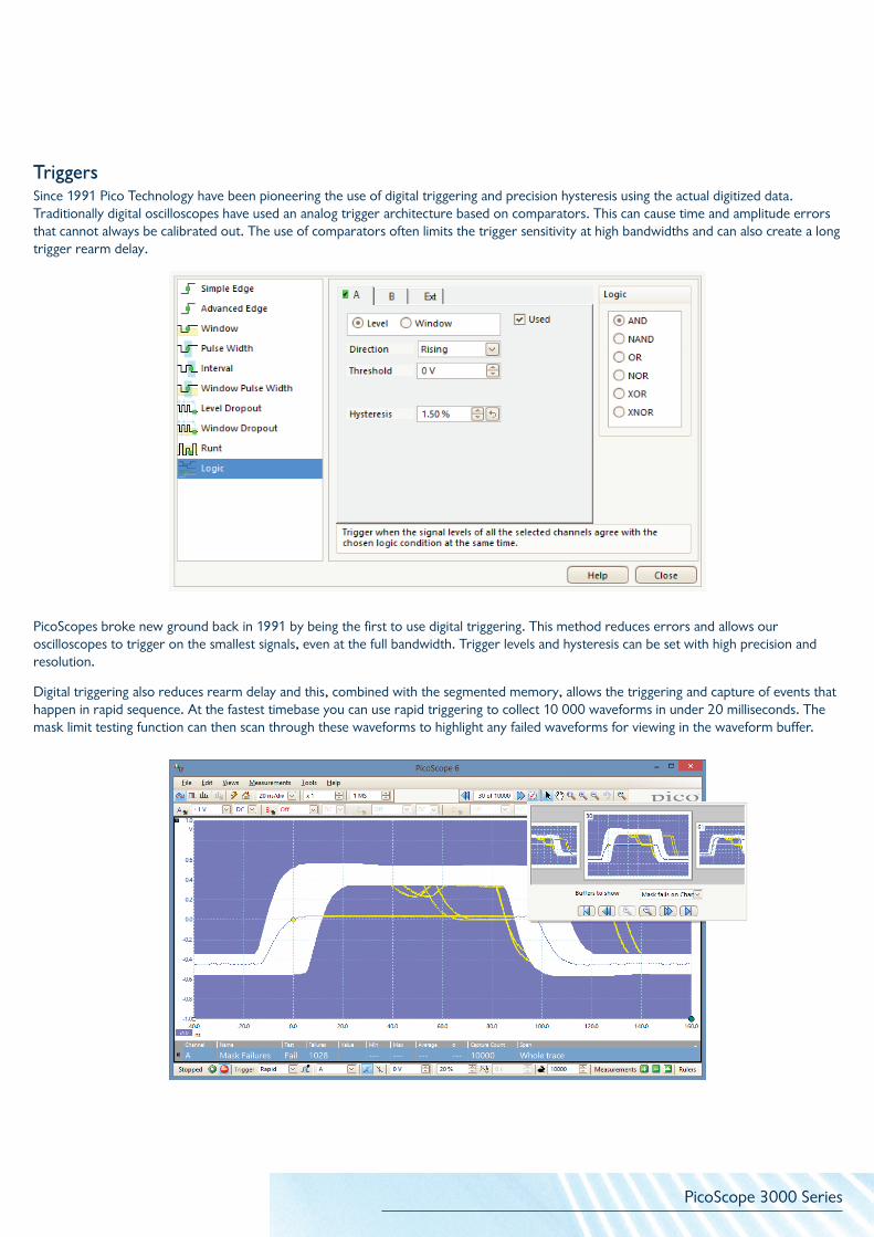
TriggersSince 1991 Pico Technology have been pioneering the use of digital triggering and precision hysteresis using the actual digitized data. Traditionally digital oscilloscopes have used an analog trigger architecture based on comparators. This can cause time and amplitude errors that cannot always be calibrated out. The use of comparators often limits the trigger sensitivity at high bandwidths and can also create a long trigger rearm delay.
PicoScopes broke new ground back in 1991 by being the first to use digital triggering. This method reduces errors and allows our oscilloscopes to trigger on the smallest signals, even at the full bandwidth. Trigger levels and hysteresis can be set with high precision and resolution.
Digital triggering also reduces rearm delay and this, combined with the segmented memory, allows the triggering and capture of events that happen in rapid sequence. At the fastest timebase you can use rapid triggering to collect 10 000 waveforms in under 20 milliseconds. The mask limit testing function can then scan through these waveforms to highlight any failed waveforms for viewing in the waveform buffer.
PicoScope 3000 Series
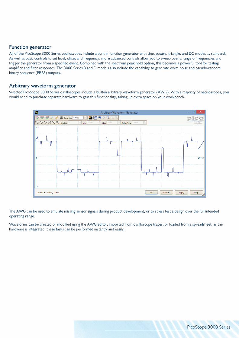
Function generatorAll of the PicoScope 3000 Series oscilloscopes include a built-in function generator with sine, square, triangle, and DC modes as standard. As well as basic controls to set level, offset and frequency, more advanced controls allow you to sweep over a range of frequencies and trigger the generator from a specified event. Combined with the spectrum peak hold option, this becomes a powerful tool for testing amplifier and filter responses. The 3000 Series B and D models also include the capability to generate white noise and pseudo-random binary sequence (PRBS) outputs.
Arbitrary waveform generatorSelected PicoScope 3000 Series oscilloscopes include a built-in arbitrary waveform generator (AWG). With a majority of oscilloscopes, you would need to purchase separate hardware to gain this functionality, taking up extra space on your workbench.
The AWG can be used to emulate missing sensor signals during product development, or to stress test a design over the full intended operating range.
Waveforms can be created or modified using the AWG editor, imported from oscilloscope traces, or loaded from a spreadsheet; as the hardware is integrated, these tasks can be performed instantly and easily.

PicoScope 3000 Series
Hardware acceleration and data aggregationFor a majority of setups, the data collection speed of the PicoScope will be faster than the USB transfer rate, and so information has to be stored in high-speed memory on the device. However, even deep-memory devices are required to have fast waveform update rates. For instance, the PicoScope 3207B can sample at 1 GS/s for timebases as long as 20 ms/div, capturing 200 million samples per waveform, and still update several times per second.
To ensure these fast waveform update rates, and to prevent a bottleneck of raw data, hardware acceleration is required to avoid the PC’s CPU having to process every sample. Hardware acceleration enables the oscilloscope to intelligently compress the raw ADC data stored in its memory before transferring it to the PC.
Traditionally, the oscilloscope would perform a simple decimation and only transfer every nth sample, resulting in the vast majority of data being lost (up to 99.999%) and a lack of high-frequency information.
PicoScope deep-memory oscilloscopes perform data aggregation instead. Dedicated logic divides the memory into blocks, and transfers the minimum and maximum values of each block to the PC, preserving the high-frequency data. For example, a waveform with 100 million samples may be divided into 1 000 blocks of 100 000 samples each, with only the minimum and maximum values for each block being transferred back to the PC. If a zoom is applied to the waveform, the oscilloscope will again divide the selected area into blocks and transfer the minimum and maximum data, so that fine detail is rapidly viewable.
In the example above, both waveforms show the same signal, but using different types of hardware acceleration. The top waveform has used the aggregation possible with a PicoScope, and as a result the high-frequency spikes are preserved. The bottom waveform has used traditional decimation, and shows a loss of signal data.
In parallel with the data aggregation, other data such as average values are also returned to speed up measurements and to reduce the number of occasions where we do have to use the PC’s processor.
When the trace length is set to be shorter than the scope’s memory, the PicoScope will automatically configure the memory as a circular buffer, recording recent waveforms for review. For example, if 1 million samples are captured, up to 500 waveforms will be stored in oscilloscope memory. Tools such as mask limit testing can then be used to scan through each waveform to identify anomalies.
Furthermore, as the hardware acceleration is performed with an FPGA, improvements to your scope’s hardware can be made through regular, free software upgrades: no physical updates to your PicoScope are required.
PicoScope 3000 Series
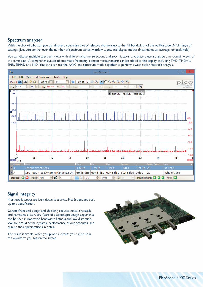
Spectrum analyzerWith the click of a button you can display a spectrum plot of selected channels up to the full bandwidth of the oscilloscope. A full range of settings gives you control over the number of spectrum bands, window types, and display modes (instantaneous, average, or peak-hold).
You can display multiple spectrum views with different channel selections and zoom factors, and place these alongside time-domain views of the same data. A comprehensive set of automatic frequency-domain measurements can be added to the display, including THD, THD+N, SNR, SINAD and IMD. You can even use the AWG and spectrum mode together to perform swept scalar network analysis.
Signal integrityMost oscilloscopes are built down to a price. PicoScopes are built up to a specification.
Careful front-end design and shielding reduces noise, crosstalk and harmonic distortion. Years of oscilloscope design experience can be seen in improved bandwidth flatness and low distortion. We are proud of the dynamic performance of our products, and publish their specifications in detail.
The result is simple: when you probe a circuit, you can trust in the waveform you see on the screen.

PicoScope 3000 Series
USB connectivityThe USB connection not only allows high-speed data acquisition and transfer, but also makes printing, copying, saving, and emailing your data from the field quick and easy. USB powering removes the need to carry around a bulky external power supply, making the kit even more portable for the engineer on the move.
Selected PicoScope 3000 Series oscilloscopes now also feature a SuperSpeed USB 3.0 connection, making the already-optimized process of data transfer even faster.
Further benefits of a USB 3.0 connection include faster saving of waveforms and faster gap-free continuous streaming of up to
125 MS/s when using the SDK, while the scope is still backward-compatible with older USB systems.
High-end features as standardBuying a PicoScope is not like making a purchase from other oscilloscope companies, where optional extras considerably increase the price. With our scopes, high-end features such as resolution enhancement, mask limit testing, serial decoding, advanced triggering, automatic measurements, math channels, XY mode, segmented memory, and a signal generator are all included in the price.
To protect your investment, both the PC software and firmware inside the scope can be updated. Pico Technology have a long history of providing new features for free through software downloads. We deliver on our promises of future enhancements year after year, unlike many other companies in the field. Users of our products reward us by becoming lifelong customers and frequently recommending us to their colleagues.
PicoScope 3000 Series
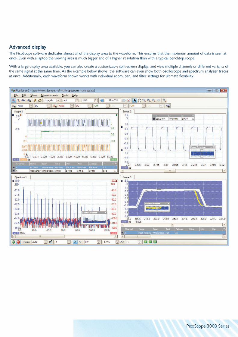
Advanced displayThe PicoScope software dedicates almost all of the display area to the waveform. This ensures that the maximum amount of data is seen at once. Even with a laptop the viewing area is much bigger and of a higher resolution than with a typical benchtop scope.
With a large display area available, you can also create a customizable split-screen display, and view multiple channels or different variants of the same signal at the same time. As the example below shows, the software can even show both oscilloscope and spectrum analyzer traces at once. Additionally, each waveform shown works with individual zoom, pan, and filter settings for ultimate flexibility.

PicoScope 3000 Series
Color persistence mode allows you to see old and new data superimposed, with new data in a brighter color or shade. This makes it easy to see glitches and dropouts and to estimate their relative frequency. Choose between analog persistence and digital color, or create custom display modes.
Math channelsWith PicoScope 6 you can perform a variety of mathematical calculations on your input signals and reference waveforms.
Use the built-in list for simple functions such as addition and inversion, or open the equation editor and create complex functions involving trigonometry, exponentials, logarithms, statistics, integrals and derivatives.
Custom probe settingsCustom probes allow you to correct for gain, attenuation, offsets and nonlinearities of probes and transducers, or convert to different measurement units such as current, power or temperature. Definitions for standard Pico-supplied probes are built in, but you can also create your own using linear scaling or even an interpolated data table, and save them for later use.
Color persistence mode

PicoScope 3000 Series
Serial decodingThe deep-memory PicoScope 3000 Series oscilloscopes include serial decoding capability across all channels, and are ideal for this job as they can capture thousands of frames of uninterrupted data.
The decoded data can be displayed in the format of your choice: In graph, In table, or both at once.
• In graph format shows the decoded data beneath the waveform on a common time axis, with error frames marked in red. These frames can be zoomed to investigate noise or distortion.
• In table format shows a list of the decoded frames, including the data and all flags and identifiers. You can set up filtering conditions to display only the frames you are interested in, search for frames with specified properties, or define a start pattern to signal when the program should list the data.
PicoScope can also import a spreadsheet to decode the numerical data into user-defined text strings.
In graph
In table
Serial protocolsUART/RS-232
SPI
I2C
I2SCAN
LIN
FlexRay
High-speed data acquisition and digitizerThe supplied drivers and software development kit (SDK) allows you to write your own software or interface to popular third-party software packages such as National Instruments LabVIEW and MathWorks MATLAB.
The driver supports data streaming, a mode which captures gap-free continuous data over USB direct to the PC’s RAM or hard disk at rates of up to 125 MS/s and capture sizes limited only by available PC storage. Sampling rates in streaming mode are subject to PC specifications and application loading.

PicoScope 3000 Series
Automatic measurementsPicoScope allows you to display a table of calculated measurements for troubleshooting and analysis.
Using the built-in measurement statistics you can see the average, standard deviation, maximum and minimum of each measurement as well as the live value. You can add as many measurements as you need on each view. For information on the measurements available in scope and spectrum modes, see Automatic Measurements in the Specifications table.
Mask limit testingMask limit testing allows you to compare live signals against known good signals, and is designed for production and debugging environments. Simply capture a known good signal, draw a mask around it, and then attach the system under test. PicoScope will capture any intermittent glitches and can show a failure count and other statistics in the Measurements window.
The numerical and graphical mask editors can be used separately or in combination, allowing you to enter accurate mask specifications, modify existing masks, and import and export masks as files.
PicoScope 3000 Series
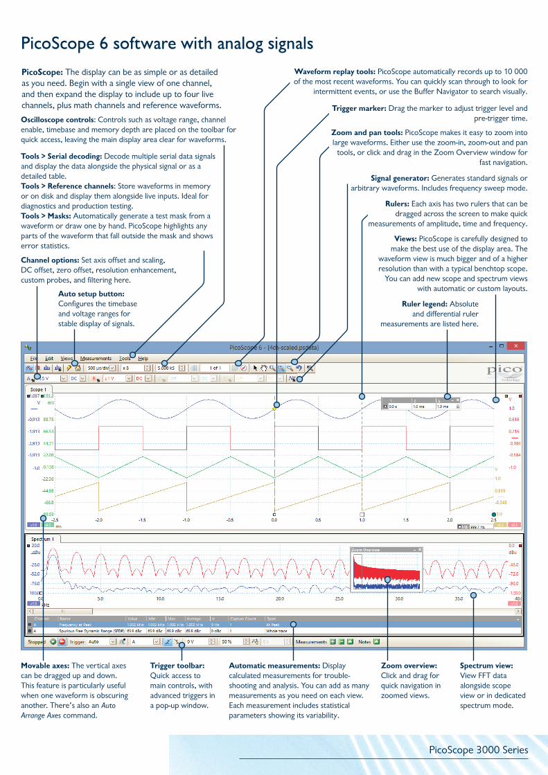
Tools > Serial decoding: Decode multiple serial data signals and display the data alongside the physical signal or as a detailed table.Tools > Reference channels: Store waveforms in memory or on disk and display them alongside live inputs. Ideal for diagnostics and production testing.Tools > Masks: Automatically generate a test mask from a waveform or draw one by hand. PicoScope highlights any parts of the waveform that fall outside the mask and shows error statistics.
Movable axes: The vertical axes can be dragged up and down. This feature is particularly useful when one waveform is obscuring another. There’s also an Auto Arrange Axes command.
Zoom overview: Click and drag for quick navigation in zoomed views.
Spectrum view: View FFT data alongside scope view or in dedicated spectrum mode.
Automatic measurements: Display calculated measurements for trouble-shooting and analysis. You can add as many measurements as you need on each view. Each measurement includes statistical parameters showing its variability.
Trigger toolbar: Quick access to main controls, with advanced triggers in a pop-up window.
Ruler legend: Absolute and differential ruler
measurements are listed here.
Channel options: Set axis offset and scaling, DC offset, zero offset, resolution enhancement, custom probes, and filtering here.
PicoScope: The display can be as simple or as detailed as you need. Begin with a single view of one channel, and then expand the display to include up to four live channels, plus math channels and reference waveforms.
Rulers: Each axis has two rulers that can be dragged across the screen to make quick
measurements of amplitude, time and frequency.
Views: PicoScope is carefully designed to make the best use of the display area. The
waveform view is much bigger and of a higher resolution than with a typical benchtop scope.
You can add new scope and spectrum views with automatic or custom layouts.
Signal generator: Generates standard signals or arbitrary waveforms. Includes frequency sweep mode.
Auto setup button:Configures the timebase and voltage ranges for stable display of signals.
PicoScope 6 software with analog signals
Oscilloscope controls: Controls such as voltage range, channel enable, timebase and memory depth are placed on the toolbar for quick access, leaving the main display area clear for waveforms.
Zoom and pan tools: PicoScope makes it easy to zoom into large waveforms. Either use the zoom-in, zoom-out and pan
tools, or click and drag in the Zoom Overview window for fast navigation.
Trigger marker: Drag the marker to adjust trigger level and pre-trigger time.
Waveform replay tools: PicoScope automatically records up to 10 000 of the most recent waveforms. You can quickly scan through to look for
intermittent events, or use the Buffer Navigator to search visually.

PicoScope 3000 Series
The PicoScope 3000 Series Mixed-Signal Oscilloscopes (MSOs) include 16 digital inputs alongside the standard 2 or 4 analog channels, so that you can view your digital and analog signals simultaneously.
These models include the same features as other PicoScope 3000 Series oscilloscopes, such as SuperSpeed USB 3.0 connectivity, deep memory, and a built-in arbitrary waveform generator, as well as functions such as mask limit testing, math and reference channels, advanced triggers, serial decoding, and automatic measurements.
Mixed-signal oscilloscopes
Serial decoding for digital signalsThe PicoScope 3000 Series MSO models bring extra power to the serial decoding features outlined in Serial decoding for analog signals. You can decode serial data on all analog and digital inputs simultaneously, giving you up to 20 channels of data with any combination of serial protocols!
As well as simple edge triggers, a selection of time-based triggers are available for both digital and analog inputs.
• The pulse-width trigger allows you to trigger on either “high” or “low” pulses, which are shorter or longer than a specified time, or which fall inside or outside a range of times.
• The interval trigger measures the time between subsequent rising or falling edges. This allows you to trigger if a clock signal falls outside of an acceptable frequency range, for example.
• The dropout trigger fires when a signal stops toggling for a defined interval of time, functioning rather like a watchdog timer.
Digital triggersThe PicoScope 3000 Series MSO models offer a comprehensive set of advanced triggers covering both the analog and digital inputs, to help you capture the data you need.
Logic triggering allows you to trigger the scope when any or all of the 16 digital inputs match a user-defined pattern. You can specify a condition for each channel individually, or set up a pattern for all channels at once using a hexadecimal or binary value. You can also combine logic triggering with an edge trigger on any one of the digital or analog inputs, to trigger on data values in a clocked parallel bus for example.

PicoScope 3000 Series
The 16 digital inputs can be displayed individually or in arbitrary groups labelled with binary, decimal or hexadecimal values. A separate logic threshold from –5 V to +5 V can be defined for each 8-bit input port. The digital trigger can be activated by any bit pattern combined with an optional transition on any input.
Advanced logic triggers can be set on either the analog or the digital input channels, or both.
Digital channels To view the digital signals in the PicoScope 6 software, simply click the digital channels button. Channels can be added to the view by dragging and dropping, and can then be reordered, grouped, and renamed.
Analog
Digital
PicoScope 3000 Series
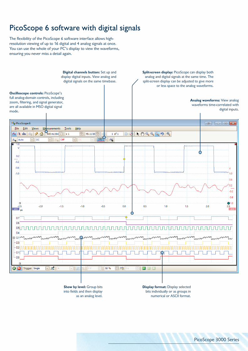
The flexibility of the PicoScope 6 software interface allows high-resolution viewing of up to 16 digital and 4 analog signals at once. You can use the whole of your PC’s display to view the waveforms, ensuring you never miss a detail again.
PicoScope 6 software with digital signals
Display format: Display selected bits individually or as groups in
numerical or ASCII format.
Show by level: Group bits into fields and then display
as an analog level.
Split-screen display: PicoScope can display both analog and digital signals at the same time. The
split-screen display can be adjusted to give more or less space to the analog waveforms.
Analog waveforms: View analog waveforms time-correlated with
digital inputs.
Digital channels button: Set up and display digital inputs. View analog and
digital signals on the same timebase.
Oscilloscope controls: PicoScope’s full analog-domain controls, including zoom, filtering, and signal generator, are all available in MSO digital signal mode.
PicoScope 3000 Series
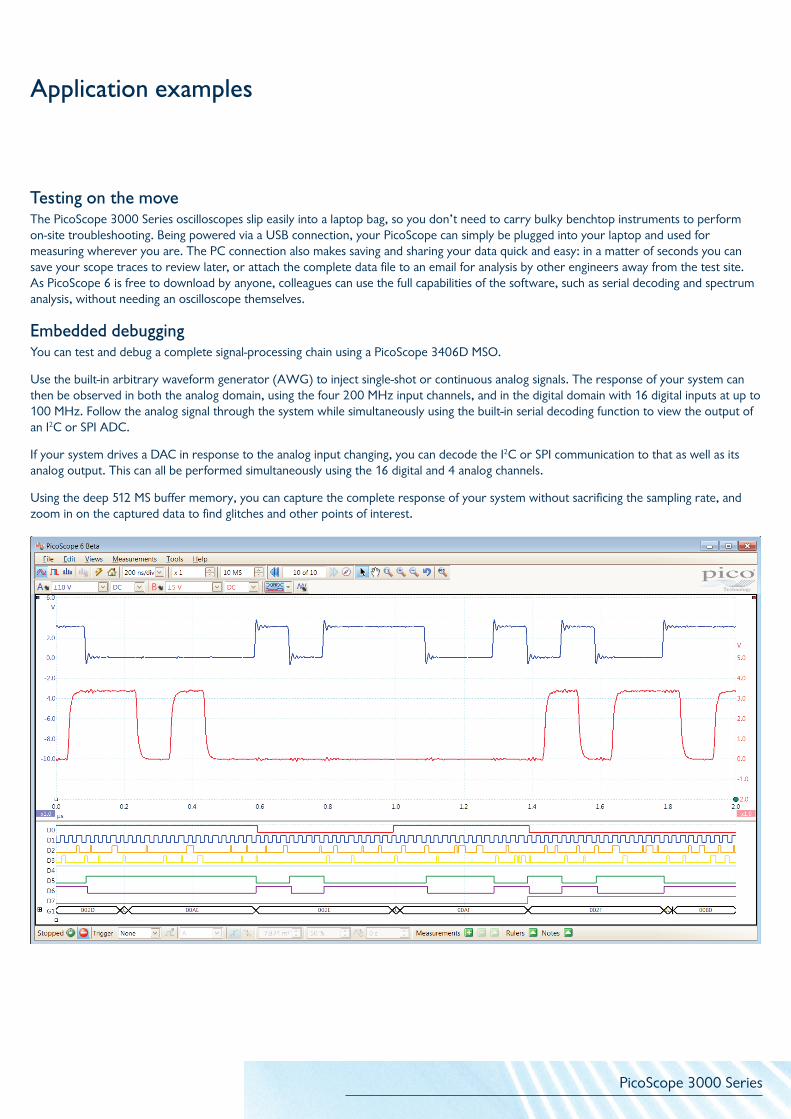
Embedded debuggingYou can test and debug a complete signal-processing chain using a PicoScope 3406D MSO.
Use the built-in arbitrary waveform generator (AWG) to inject single-shot or continuous analog signals. The response of your system can then be observed in both the analog domain, using the four 200 MHz input channels, and in the digital domain with 16 digital inputs at up to 100 MHz. Follow the analog signal through the system while simultaneously using the built-in serial decoding function to view the output of an I2C or SPI ADC.
If your system drives a DAC in response to the analog input changing, you can decode the I2C or SPI communication to that as well as its analog output. This can all be performed simultaneously using the 16 digital and 4 analog channels.
Using the deep 512 MS buffer memory, you can capture the complete response of your system without sacrificing the sampling rate, and zoom in on the captured data to find glitches and other points of interest.
Application examples
Testing on the move The PicoScope 3000 Series oscilloscopes slip easily into a laptop bag, so you don’t need to carry bulky benchtop instruments to perform on-site troubleshooting. Being powered via a USB connection, your PicoScope can simply be plugged into your laptop and used for measuring wherever you are. The PC connection also makes saving and sharing your data quick and easy: in a matter of seconds you can save your scope traces to review later, or attach the complete data file to an email for analysis by other engineers away from the test site. As PicoScope 6 is free to download by anyone, colleagues can use the full capabilities of the software, such as serial decoding and spectrum analysis, without needing an oscilloscope themselves.

PicoScope 3000 Series
PicoScope 3204 A/B PicoScope 3205 A/B PicoScope 3206 A/B PicoScope 3207 A/B
VerticalInput channels 2 channels, BNC single-ended
Bandwidth (–3 dB) 60 MHz 100 MHz 200 MHz 250 MHz
Rise time (calculated) 5.8 ns 3.5 ns 1.75 ns 1.4 ns
Vertical resolution 8 bits
Input ranges ±50 mV to ±20 V full scale in 9 ranges
Input sensitivity 10 mV/div to 4 V/div (10 vertical divisions)
Input coupling AC / DC
Input characteristics 1 MΩ ±1%, in parallel with 13 pF ±1 pF
DC accuracy ±3% of full scale
Analog offset range(vertical position adjust)
±250 mV (50 mV to 200 mV ranges) ±2.5 V (500 mV to 2 V ranges)
±20 V (5 V to 20 V ranges)
Offset adjust accuracy ±1% of offset setting, additional to DC accuracy
Overvoltage protection ±100 V (DC + AC peak)
HorizontalMaximum sampling rate
(real-time)500 MS/s (1 channel in use)250 MS/s (2 channels in use)
1 GS/s (1 ch. in use)500 MS/s (2 chs. in use)
Maximum equivalent-time sampling rate
(repetitive signals)2.5 GS/s 5 GS/s 10 GS/s 10 GS/s
Maximum sampling rate (streaming)
10 MS/s in PicoScope software> 10 MS/s using the supplied SDK (PC-dependent)
10 MS/s in PicoScope software
125 MS/s when using supplied SDK
(PC-dependent)Timebase ranges
(real-time)2 ns/div to 5000 s/div 1 ns/div to 5000 s/div 500 ps/div to 5000 s/div 500 ps/div to 5000 s/div
Buffer memory4 MS
(A model)8 MS
(B model)16 MS
(A model)32 MS
(B model)64 MS
(A model)128 MS
(B model)256 MS
(A model)512 MS
(B model)Buffer memory
(streaming)100 MS in PicoScope software
Up to available PC memory when using supplied SDK
Maximum buffer segments 10 000
Timebase accuracy ±50 ppm ±2 ppm ±1 ppm/year
Sample jitter < 5 ps RMS typical < 3 ps RMS typical
TriggeringTrigger modes None, auto, repeat, single, rapid (segmented memory)
Advanced trigger types Edge, window, pulse width, window pulse width, dropout, window dropout, interval, logic, runt pulse
Trigger sensitivity Digital triggering provides 1 LSB accuracy up to full bandwidth of scope
Trigger types (ETS mode) Rising edge, falling edge
Trigger sensitivity (ETS mode)
10 mV p-p typical (at full bandwidth)
Maximum pre-trigger capture
Up to 100% of capture size
Maximum post-trigger delay
Up to 4 billion samples (selectable in 1 sample steps)
Trigger rearm time < 2 μs on fastest timebase < 1 μs on fastest timebase
Maximum trigger rate Up to 10 000 waveforms in a 20 ms burstUp to 10 000 waveforms
in a 10 ms burst
Detailed specifications for 2-channel models
PicoScope 3000 Series
PicoScope 3204 A/B PicoScope 3205 A/B PicoScope 3206 A/B PicoScope 3207 A/B
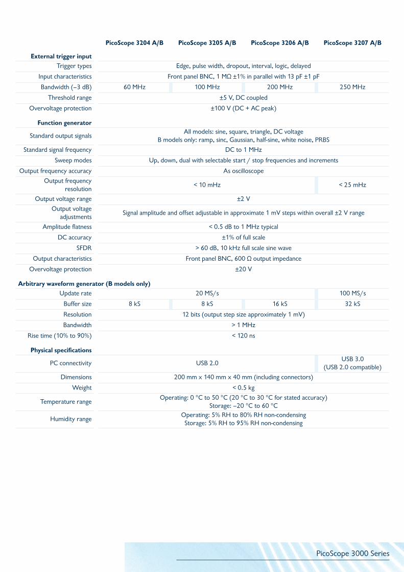
External trigger inputTrigger types Edge, pulse width, dropout, interval, logic, delayed
Input characteristics Front panel BNC, 1 MΩ ±1% in parallel with 13 pF ±1 pF
Bandwidth (–3 dB) 60 MHz 100 MHz 200 MHz 250 MHz
Threshold range ±5 V, DC coupled
Overvoltage protection ±100 V (DC + AC peak)
Function generator
Standard output signalsAll models: sine, square, triangle, DC voltage
B models only: ramp, sinc, Gaussian, half-sine, white noise, PRBS
Standard signal frequency DC to 1 MHz
Sweep modes Up, down, dual with selectable start / stop frequencies and increments
Output frequency accuracy As oscilloscope
Output frequency resolution
< 10 mHz < 25 mHz
Output voltage range ±2 V
Output voltageadjustments
Signal amplitude and offset adjustable in approximate 1 mV steps within overall ±2 V range
Amplitude flatness < 0.5 dB to 1 MHz typical
DC accuracy ±1% of full scale
SFDR > 60 dB, 10 kHz full scale sine wave
Output characteristics Front panel BNC, 600 Ω output impedance
Overvoltage protection ±20 V
Arbitrary waveform generator (B models only)Update rate 20 MS/s 100 MS/s
Buffer size 8 kS 8 kS 16 kS 32 kS
Resolution 12 bits (output step size approximately 1 mV)
Bandwidth > 1 MHz
Rise time (10% to 90%) < 120 ns
Physical specifications
PC connectivity USB 2.0USB 3.0
(USB 2.0 compatible)
Dimensions 200 mm x 140 mm x 40 mm (including connectors)
Weight < 0.5 kg
Temperature rangeOperating: 0 °C to 50 °C (20 °C to 30 °C for stated accuracy)
Storage: –20 °C to 60 °C
Humidity rangeOperating: 5% RH to 80% RH non-condensingStorage: 5% RH to 95% RH non-condensing
PicoScope 3000 Series
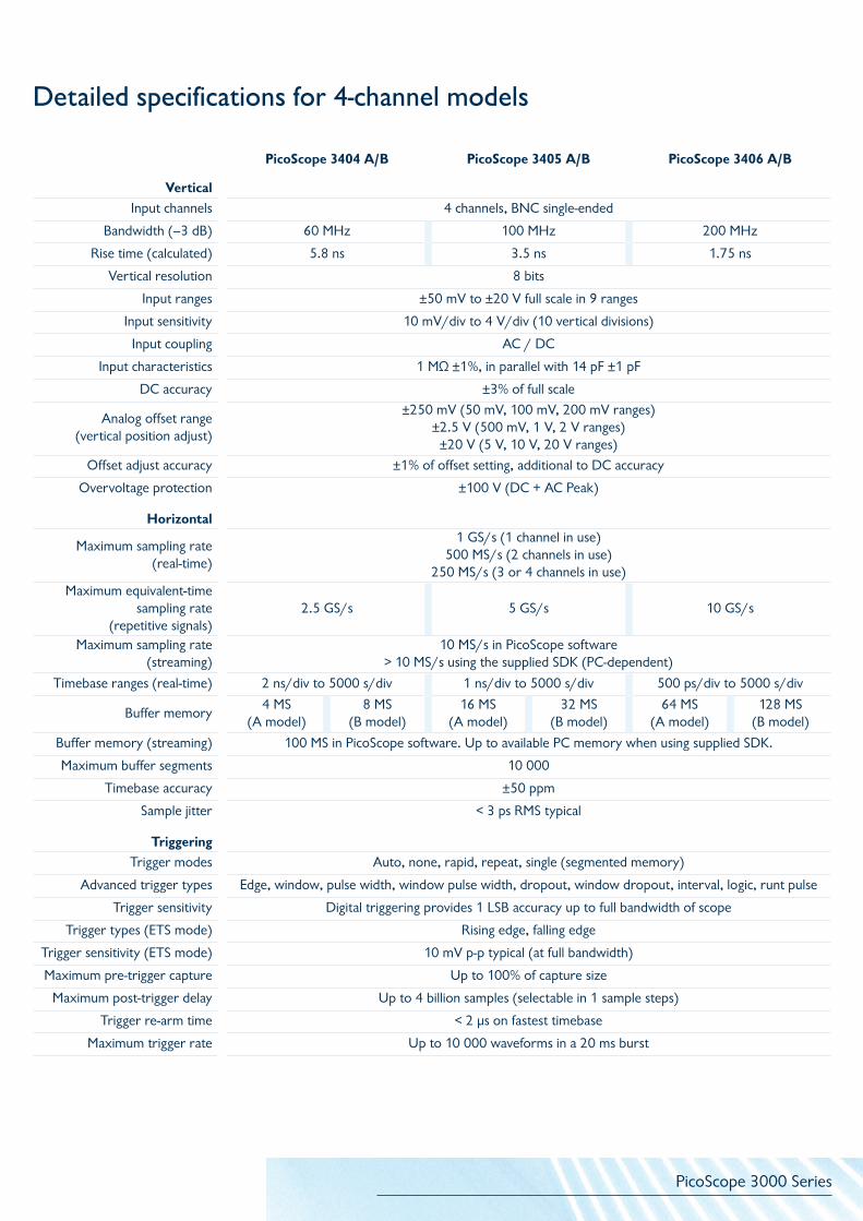
Detailed specifications for 4-channel models
PicoScope 3404 A/B PicoScope 3405 A/B PicoScope 3406 A/B
VerticalInput channels 4 channels, BNC single-ended
Bandwidth (–3 dB) 60 MHz 100 MHz 200 MHz
Rise time (calculated) 5.8 ns 3.5 ns 1.75 ns
Vertical resolution 8 bits
Input ranges ±50 mV to ±20 V full scale in 9 ranges
Input sensitivity 10 mV/div to 4 V/div (10 vertical divisions)
Input coupling AC / DC
Input characteristics 1 MΩ ±1%, in parallel with 14 pF ±1 pF
DC accuracy ±3% of full scale
Analog offset range (vertical position adjust)
±250 mV (50 mV, 100 mV, 200 mV ranges)±2.5 V (500 mV, 1 V, 2 V ranges)
±20 V (5 V, 10 V, 20 V ranges)
Offset adjust accuracy ±1% of offset setting, additional to DC accuracy
Overvoltage protection ±100 V (DC + AC Peak)
Horizontal
Maximum sampling rate (real-time)
1 GS/s (1 channel in use)500 MS/s (2 channels in use)
250 MS/s (3 or 4 channels in use)Maximum equivalent-time
sampling rate (repetitive signals)
2.5 GS/s 5 GS/s 10 GS/s
Maximum sampling rate (streaming)
10 MS/s in PicoScope software> 10 MS/s using the supplied SDK (PC-dependent)
Timebase ranges (real-time) 2 ns/div to 5000 s/div 1 ns/div to 5000 s/div 500 ps/div to 5000 s/div
Buffer memory4 MS
(A model)8 MS
(B model)16 MS
(A model)32 MS
(B model)64 MS
(A model)128 MS
(B model)
Buffer memory (streaming) 100 MS in PicoScope software. Up to available PC memory when using supplied SDK.
Maximum buffer segments 10 000
Timebase accuracy ±50 ppm
Sample jitter < 3 ps RMS typical
TriggeringTrigger modes Auto, none, rapid, repeat, single (segmented memory)
Advanced trigger types Edge, window, pulse width, window pulse width, dropout, window dropout, interval, logic, runt pulse
Trigger sensitivity Digital triggering provides 1 LSB accuracy up to full bandwidth of scope
Trigger types (ETS mode) Rising edge, falling edge
Trigger sensitivity (ETS mode) 10 mV p-p typical (at full bandwidth)
Maximum pre-trigger capture Up to 100% of capture size
Maximum post-trigger delay Up to 4 billion samples (selectable in 1 sample steps)
Trigger re-arm time < 2 µs on fastest timebase
Maximum trigger rate Up to 10 000 waveforms in a 20 ms burst
PicoScope 3000 Series
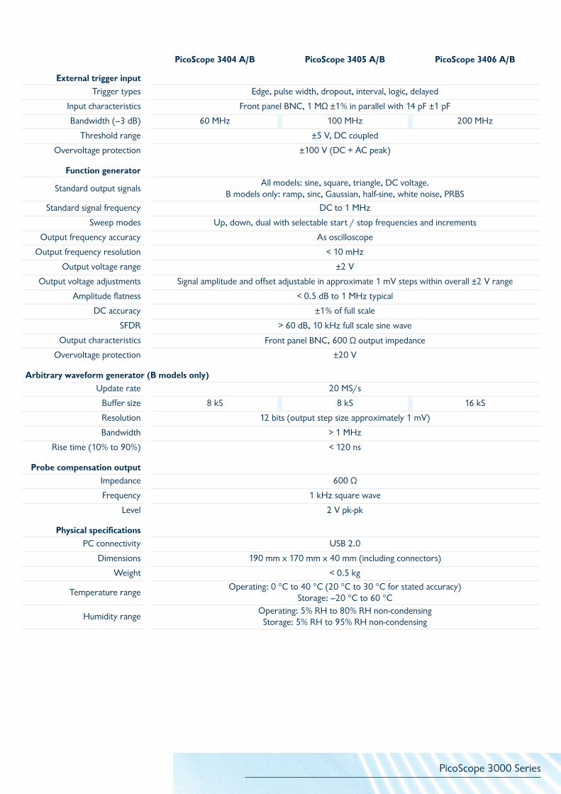
PicoScope 3404 A/B PicoScope 3405 A/B PicoScope 3406 A/B
External trigger inputTrigger types Edge, pulse width, dropout, interval, logic, delayed
Input characteristics Front panel BNC, 1 MΩ ±1% in parallel with 14 pF ±1 pF
Bandwidth (–3 dB) 60 MHz 100 MHz 200 MHz
Threshold range ±5 V, DC coupled
Overvoltage protection ±100 V (DC + AC peak)
Function generator
Standard output signalsAll models: sine, square, triangle, DC voltage.
B models only: ramp, sinc, Gaussian, half-sine, white noise, PRBS
Standard signal frequency DC to 1 MHz
Sweep modes Up, down, dual with selectable start / stop frequencies and increments
Output frequency accuracy As oscilloscope
Output frequency resolution < 10 mHz
Output voltage range ±2 V
Output voltage adjustments Signal amplitude and offset adjustable in approximate 1 mV steps within overall ±2 V range
Amplitude flatness < 0.5 dB to 1 MHz typical
DC accuracy ±1% of full scale
SFDR > 60 dB, 10 kHz full scale sine wave
Output characteristics Front panel BNC, 600 Ω output impedance
Overvoltage protection ±20 V
Arbitrary waveform generator (B models only)Update rate 20 MS/s
Buffer size 8 kS 8 kS 16 kS
Resolution 12 bits (output step size approximately 1 mV)
Bandwidth > 1 MHz
Rise time (10% to 90%) < 120 ns
Probe compensation outputImpedance 600 Ω
Frequency 1 kHz square wave
Level 2 V pk-pk
Physical specificationsPC connectivity USB 2.0
Dimensions 190 mm x 170 mm x 40 mm (including connectors)
Weight < 0.5 kg
Temperature rangeOperating: 0 °C to 40 °C (20 °C to 30 °C for stated accuracy)
Storage: –20 °C to 60 °C
Humidity rangeOperating: 5% RH to 80% RH non-condensingStorage: 5% RH to 95% RH non-condensing

PicoScope 3000 Series
PicoScope 3204D MSO
PicoScope 3205D MSO
PicoScope 3206D MSO
PicoScope 3404D MSO
PicoScope 3405D MSO
PicoScope 3406D MSO
Vertical (analog)Input channels 2 channels, BNC single-ended 4 channels, BNC single-ended
Bandwidth (–3 dB) 60 MHz 100 MHz 200 MHz 60 MHz 100 MHz 200 MHz
Rise time (calculated) 5.8 ns 3.5 ns 1.75 ns 5.8 ns 3.5 ns 1.75 ns
Vertical resolution 8 bits
Input ranges ±20 mV to ±20 V full scale in 10 ranges
Input sensitivity 4 mV/div to 4 V/div in 10 vertical divisions
Input coupling AC / DC
Input characteristics 1 MΩ ±1%, in parallel with 14 pF ±1 pF
DC accuracy ±3% of full scale ±200 µV
Analog offset range (vertical position adjust)
±250 mV (20 mV, 50 mV, 100 mV, 200 mV ranges) ±2.5 V (500 mV, 1 V, 2 V ranges)
±20 V (5 V, 10 V, 20 V ranges)
Offset adjust accuracy ±1% of offset setting, additional to DC accuracy
Overvoltage protection ±100 V (DC + AC peak)
Vertical (digital)Input channels 16 channels (2 ports of 8 channels each)
Input connectors 2.54 mm pitch, 10 x 2 way connector
Maximum input frequency 100 MHz
Minimum detectable pulse width 5 ns
Input impedance (with TA136 cable) 200 kΩ ±2% ∥ 8 pF ±2 pF
Digital threshold range ±5 V
Input dynamic range ±20 V
Overvoltage protection ±50 V
Threshold grouping Two independent threshold controls: Port 0 (D0 to D7), Port 1 (D8 to D15)
Threshold selection TTL, CMOS, ECL, PECL, user-defined
Threshold accuracy ±100 mV
Minimum input voltage swing 500 mV pk-pk
Channel-to-channel skew < 2 ns typical
Minimum input slew rate 10 V/µs
Horizontal
Maximum sampling rate (real-time)
1 GS/s (1 analog channel in use)500 MS/s (Up to 2 analog channels or digital ports* in use)250 MS/s (Up to 4 analog channels or digital ports* in use)
125 MS/s (5 or more analog channels or digital ports* in use)*A digital port contains 8 digital channels
Maximum equivalent-time sampling rate (repetitive signals)* 2.5 GS/s 5 GS/s 10 GS/s 2.5 GS/s 5 GS/s 10 GS/s
Maximum sampling rate (streaming)
10 MS/s in PicoScope software125 MS/s when using the supplied SDK (PC-dependent)
Timebase ranges 2 ns/div to 5000 s/div
1 ns/div to 5000 s/div
500 ps/div to 5000 s/div
2 ns/div to 5000 s/div
1 ns/div to 5000 s/div
500 ps/div to 5000 s/div
Buffer memory 128 MS 256 MS 512 MS 128 MS 256 MS 512 MS
Buffer memory (streaming) 100 MS in PicoScope software. Up to available PC memory when using supplied SDK.
Maximum buffer segments 10 000
Timebase accuracy ±50 ppm ±2 ppm ±2 ppm ±50 ppm ±2 ppm ±2 ppm
Sample jitter < 3 ps RMS typical
Detailed specifications for MSO models
PicoScope 3000 Series
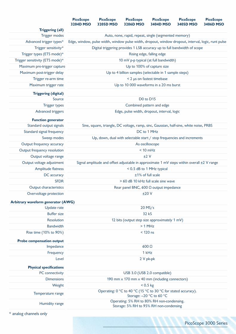
PicoScope 3204D MSO
PicoScope 3205D MSO
PicoScope 3206D MSO
PicoScope 3404D MSO
PicoScope 3405D MSO
PicoScope 3406D MSO
Triggering (all)Trigger modes Auto, none, rapid, repeat, single (segmented memory)
Advanced trigger types* Edge, window, pulse width, window pulse width, dropout, window dropout, interval, logic, runt pulse
Trigger sensitivity* Digital triggering provides 1 LSB accuracy up to full bandwidth of scope
Trigger types (ETS mode)* Rising edge, falling edge
Trigger sensitivity (ETS mode)* 10 mV p-p typical (at full bandwidth)
Maximum pre-trigger capture Up to 100% of capture size
Maximum post-trigger delay Up to 4 billion samples (selectable in 1 sample steps)
Trigger re-arm time < 2 µs on fastest timebase
Maximum trigger rate Up to 10 000 waveforms in a 20 ms burst
Triggering (digital)Source D0 to D15
Trigger types Combined pattern and edge
Advanced triggers Edge, pulse width, dropout, interval, logic
Function generatorStandard output signals Sine, square, triangle, DC voltage, ramp, sinc, Gaussian, half-sine, white noise, PRBS
Standard signal frequency DC to 1 MHz
Sweep modes Up, down, dual with selectable start / stop frequencies and increments
Output frequency accuracy As oscilloscope
Output frequency resolution < 10 mHz
Output voltage range ±2 V
Output voltage adjustment Signal amplitude and offset adjustable in approximate 1 mV steps within overall ±2 V range
Amplitude flatness < 0.5 dB to 1 MHz typical
DC accuracy ±1% of full scale
SFDR > 60 dB 10 kHz full scale sine wave
Output characteristics Rear panel BNC, 600 Ω output impedance
Overvoltage protection ±20 V
Arbitrary waveform generator (AWG)Update rate 20 MS/s
Buffer size 32 kS
Resolution 12 bits (output step size approximately 1 mV)
Bandwidth > 1 MHz
Rise time (10% to 90%) < 120 ns
Probe compensation outputImpedance 600 Ω
Frequency 1 kHz
Level 2 V pk-pk
Physical specificationsPC connectivity USB 3.0 (USB 2.0 compatible)
Dimensions 190 mm x 170 mm x 40 mm (including connectors)
Weight < 0.5 kg
Temperature rangeOperating: 0 °C to 40 °C (15 °C to 30 °C for stated accuracy).
Storage: –20 °C to 60 °C
Humidity rangeOperating: 5% RH to 80% RH non-condensing.
Storage: 5% RH to 95% RH non-condensing
* analog channels only
PicoScope 3000 Series
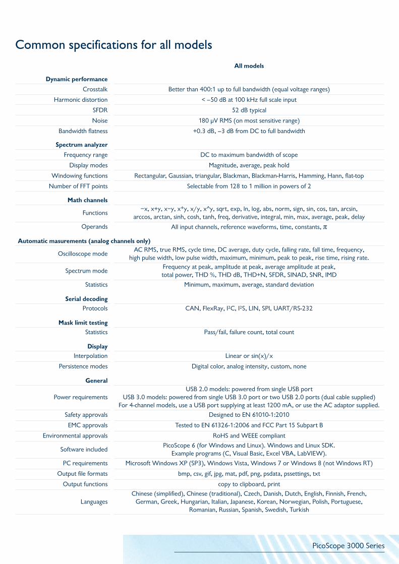
All models
Dynamic performance
Crosstalk Better than 400:1 up to full bandwidth (equal voltage ranges)
Harmonic distortion < –50 dB at 100 kHz full scale input
SFDR 52 dB typical
Noise 180 µV RMS (on most sensitive range)
Bandwidth flatness +0.3 dB, –3 dB from DC to full bandwidth
Spectrum analyzer
Frequency range DC to maximum bandwidth of scope
Display modes Magnitude, average, peak hold
Windowing functions Rectangular, Gaussian, triangular, Blackman, Blackman-Harris, Hamming, Hann, flat-top
Number of FFT points Selectable from 128 to 1 million in powers of 2
Math channels
Functions−x, x+y, x−y, x*y, x/y, x^y, sqrt, exp, ln, log, abs, norm, sign, sin, cos, tan, arcsin,
arccos, arctan, sinh, cosh, tanh, freq, derivative, integral, min, max, average, peak, delay
Operands All input channels, reference waveforms, time, constants, π
Automatic masurements (analog channels only)
Oscilloscope modeAC RMS, true RMS, cycle time, DC average, duty cycle, falling rate, fall time, frequency,
high pulse width, low pulse width, maximum, minimum, peak to peak, rise time, rising rate.
Spectrum modeFrequency at peak, amplitude at peak, average amplitude at peak, total power, THD %, THD dB, THD+N, SFDR, SINAD, SNR, IMD
Statistics Minimum, maximum, average, standard deviation
Serial decodingProtocols CAN, FlexRay, I²C, I²S, LIN, SPI, UART/RS-232
Mask limit testingStatistics Pass/fail, failure count, total count
DisplayInterpolation Linear or sin(x)/x
Persistence modes Digital color, analog intensity, custom, none
General
Power requirementsUSB 2.0 models: powered from single USB port
USB 3.0 models: powered from single USB 3.0 port or two USB 2.0 ports (dual cable supplied) For 4-channel models, use a USB port supplying at least 1200 mA, or use the AC adaptor supplied.
Safety approvals Designed to EN 61010-1:2010
EMC approvals Tested to EN 61326-1:2006 and FCC Part 15 Subpart B
Environmental approvals RoHS and WEEE compliant
Software includedPicoScope 6 (for Windows and Linux). Windows and Linux SDK.
Example programs (C, Visual Basic, Excel VBA, LabVIEW).
PC requirements Microsoft Windows XP (SP3), Windows Vista, Windows 7 or Windows 8 (not Windows RT)
Output file formats bmp, csv, gif, jpg, mat, pdf, png, psdata, pssettings, txt
Output functions copy to clipboard, print
LanguagesChinese (simplified), Chinese (traditional), Czech, Danish, Dutch, English, Finnish, French,
German, Greek, Hungarian, Italian, Japanese, Korean, Norwegian, Polish, Portuguese, Romanian, Russian, Spanish, Swedish, Turkish
Common specifications for all models

PicoScope 3000 Series
Connections
Ch B
Ch A
External trigger
AWG and function generator USB port
2-channel models
16 digital inputs
USB port
Ch B
Ch A
Earth terminalAWG and function generator
2-channel MSO models
16 digital inputsCh B
Ch A
Ch D
Ch C USB port
Earth terminal
AWG and function generator
DC power input
4-channel MSO models
Ch B
Ch A
Ch D
Ch CExternal trigger
AWG and function generator
DC power input
USB port
Earth terminal
4-channel models
Probe compensation pin
PicoScope 3000 Series
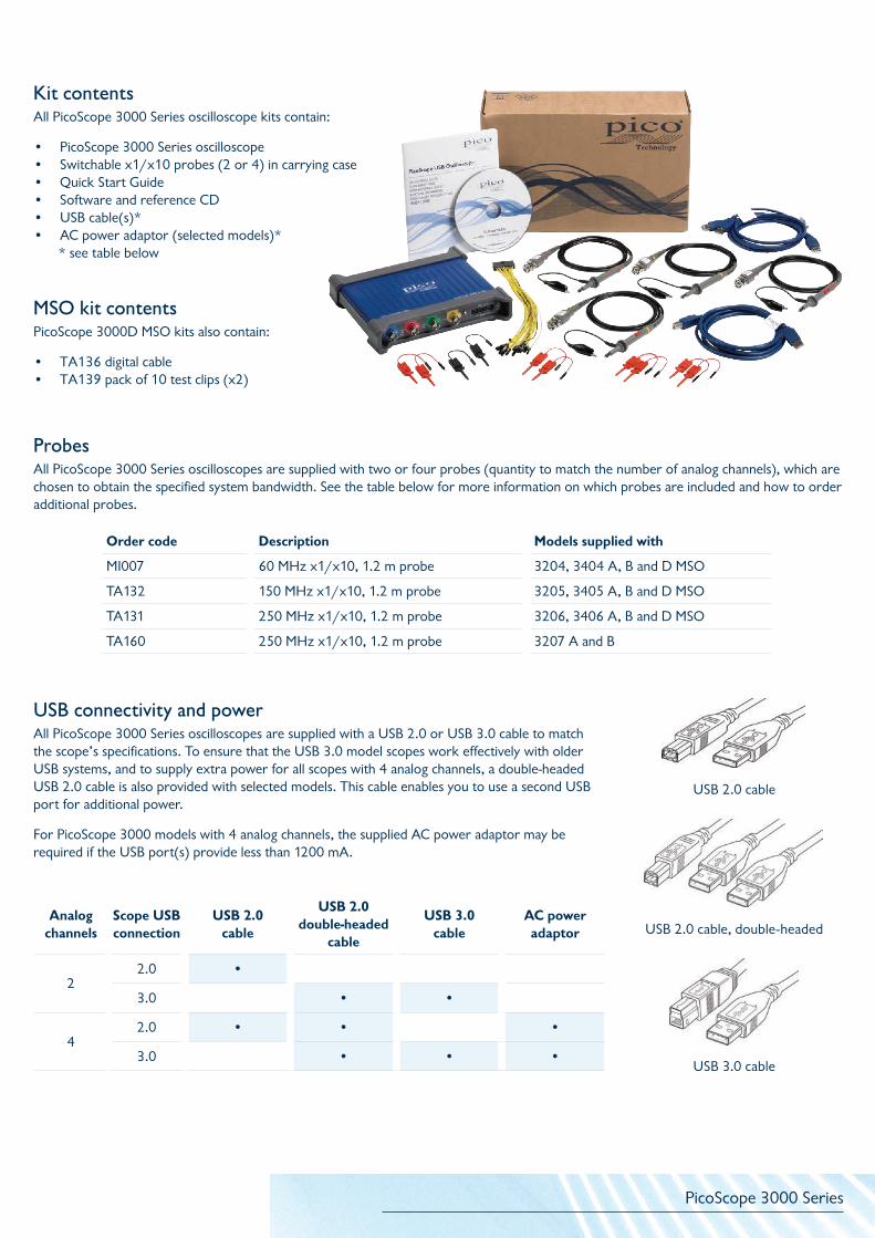
MSO kit contentsPicoScope 3000D MSO kits also contain:
• TA136 digital cable• TA139 pack of 10 test clips (x2)
Kit contents All PicoScope 3000 Series oscilloscope kits contain:
• PicoScope 3000 Series oscilloscope• Switchable x1/x10 probes (2 or 4) in carrying case• Quick Start Guide• Software and reference CD• USB cable(s)*• AC power adaptor (selected models)*
* see table below
ProbesAll PicoScope 3000 Series oscilloscopes are supplied with two or four probes (quantity to match the number of analog channels), which are chosen to obtain the specified system bandwidth. See the table below for more information on which probes are included and how to order additional probes.
Order code Description Models supplied with
MI007 60 MHz x1/x10, 1.2 m probe 3204, 3404 A, B and D MSO
TA132 150 MHz x1/x10, 1.2 m probe 3205, 3405 A, B and D MSO
TA131 250 MHz x1/x10, 1.2 m probe 3206, 3406 A, B and D MSO
TA160 250 MHz x1/x10, 1.2 m probe 3207 A and B
USB connectivity and powerAll PicoScope 3000 Series oscilloscopes are supplied with a USB 2.0 or USB 3.0 cable to match the scope’s specifications. To ensure that the USB 3.0 model scopes work effectively with older USB systems, and to supply extra power for all scopes with 4 analog channels, a double-headed USB 2.0 cable is also provided with selected models. This cable enables you to use a second USB port for additional power.
For PicoScope 3000 models with 4 analog channels, the supplied AC power adaptor may be required if the USB port(s) provide less than 1200 mA.
USB 2.0 cable
USB 3.0 cable
USB 2.0 cable, double-headedAnalog
channelsScope USB connection
USB 2.0 cable
USB 2.0 double-headed
cable
USB 3.0 cable
AC power adaptor
22.0 •
3.0 • •
42.0 • • •
3.0 • • •
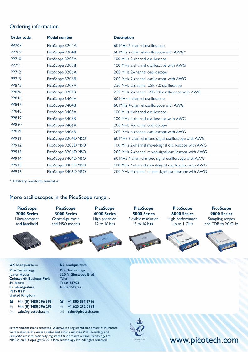
Ordering information
Order code Model number Description
PP708 PicoScope 3204A 60 MHz 2-channel oscilloscope
PP709 PicoScope 3204B 60 MHz 2-channel oscilloscope with AWG*
PP710 PicoScope 3205A 100 MHz 2-channel oscilloscope
PP711 PicoScope 3205B 100 MHz 2-channel oscilloscope with AWG
PP712 PicoScope 3206A 200 MHz 2-channel oscilloscope
PP713 PicoScope 3206B 200 MHz 2-channel oscilloscope with AWG
PP875 PicoScope 3207A 250 MHz 2-channel USB 3.0 oscilloscope
PP876 PicoScope 3207B 250 MHz 2-channel USB 3.0 oscilloscope with AWG
PP846 PicoScope 3404A 60 MHz 4-channel oscilloscope
PP847 PicoScope 3404B 60 MHz 4-channel oscilloscope with AWG
PP848 PicoScope 3405A 100 MHz 4-channel oscilloscope
PP849 PicoScope 3405B 100 MHz 4-channel oscilloscope with AWG
PP850 PicoScope 3406A 200 MHz 4-channel oscilloscope
PP851 PicoScope 3406B 200 MHz 4-channel oscilloscope with AWG
PP931 PicoScope 3204D MSO 60 MHz 2-channel mixed-signal oscilloscope with AWG
PP932 PicoScope 3205D MSO 100 MHz 2-channel mixed-signal oscilloscope with AWG
PP933 PicoScope 3206D MSO 200 MHz 2-channel mixed-signal oscilloscope with AWG
PP934 PicoScope 3404D MSO 60 MHz 4-channel mixed-signal oscilloscope with AWG
PP935 PicoScope 3405D MSO 100 MHz 4-channel mixed-signal oscilloscope with AWG
PP936 PicoScope 3406D MSO 200 MHz 4-channel mixed-signal oscilloscope with AWG
More oscilloscopes in the PicoScope range...
UK headquarters:Pico TechnologyJames HouseColmworth Business ParkSt. NeotsCambridgeshirePE19 8YP United Kingdom
+44 (0) 1480 396 395 +44 (0) 1480 396 296 [email protected]
Errors and omissions excepted. Windows is a registered trade mark of Microsoft Corporation in the United States and other countries. Pico Technology and PicoScope are internationally registered trade marks of Pico Technology Ltd.MM054.en-5. Copyright © 2014 Pico Technology Ltd. All rights reserved. www.picotech.com
US headquarters:Pico Technology320 N Glenwood BlvdTylerTexas 75702United States
+1 800 591 2796 +1 620 272 0981 [email protected]
PicoScope 2000 Series Ultra-compact and handheld
PicoScope 3000 Series
General-purposeand MSO models
PicoScope 4000 SeriesHigh precision 12 to 16 bits
PicoScope 5000 Series
Flexible resolution8 to 16 bits
PicoScope 6000 Series
High performanceUp to 1 GHz
PicoScope 9000 Series
Sampling scopesand TDR to 20 GHz
* Arbitrary waveform generator