PicoScope 3000 Series (A API) Programmer's Guide · Programmer's Guide ps3000apg.en r14 PC...
161
Programmer's Guide ps3000apg.en r14 PC Oscilloscopes and MSOs PicoScope ® 3000 Series
Transcript of PicoScope 3000 Series (A API) Programmer's Guide · Programmer's Guide ps3000apg.en r14 PC...
Programmer's Guide
ps3000apg.en r14
PC Oscilloscopes and MSOs
PicoScope® 3000 Series

IPicoScope 3000 Series (A API) Programmer's Guide
Copyright © 2011–2016 Pico Technology Limited. All rights reserved. ps3000apg.en r14
Contents1 Introduction ................................................................................................................................ 1
1 Overview ............................................................................................................................................ 1
2 License agreement .............................................................................................................................. 2
3 Trademarks ........................................................................................................................................ 2
2 Programming the PicoScope 3000 Series (A API) oscilloscopes ................................................. 3
1 Drivers ............................................................................................................................................... 3
2 Minimum PC requirements ................................................................................................................. 3
3 USB port requirements ....................................................................................................................... 3
3 Device features ........................................................................................................................... 4
1 Power options .................................................................................................................................... 4
2 Voltage ranges .................................................................................................................................... 5
3 MSO digital data ................................................................................................................................. 6
4 MSO digital connector ........................................................................................................................ 7
5 Triggering ........................................................................................................................................... 7
6 Timebases .......................................................................................................................................... 8
7 Sampling modes .................................................................................................................................. 9
1 Block mode .......................................................................................................................... 10
2 Rapid block mode ................................................................................................................. 13
3 ETS (Equivalent Time Sampling) ............................................................................................ 19
4 Streaming mode .................................................................................................................... 21
5 Retrieving stored data ........................................................................................................... 23
8 Combining several oscilloscopes ........................................................................................................ 23
4 API functions ............................................................................................................................ 24
1 ps3000aBlockReady (callback) .......................................................................................................... 26
2 ps3000aChangePowerSource ............................................................................................................ 27
3 ps3000aCloseUnit ............................................................................................................................ 28
4 ps3000aCurrentPowerSource ............................................................................................................ 29
5 ps3000aDataReady (callback) ........................................................................................................... 30
6 ps3000aEnumerateUnits ................................................................................................................... 31
7 ps3000aFlashLed .............................................................................................................................. 32
8 ps3000aGetAnalogueOffset ............................................................................................................... 33
9 ps3000aGetChannelInformation ........................................................................................................ 34
10 ps3000aGetMaxDownSampleRatio .................................................................................................. 35
11 ps3000aGetMaxEtsValues ............................................................................................................... 36
12 ps3000aGetMaxSegments ............................................................................................................... 37
13 ps3000aGetNoOfCaptures .............................................................................................................. 38
14 ps3000aGetNoOfProcessedCaptures ............................................................................................... 39
15 ps3000aGetStreamingLatestValues .................................................................................................. 40
16 ps3000aGetTimebase ...................................................................................................................... 41
17 ps3000aGetTimebase2 .................................................................................................................... 42
18 ps3000aGetTriggerInfoBulk ............................................................................................................ 43
ContentsII
Copyright © 2011–2016 Pico Technology Limited. All rights reserved.ps3000apg.en r14
19 ps3000aGetTriggerTimeOffset ........................................................................................................ 44
20 ps3000aGetTriggerTimeOffset64 .................................................................................................... 45
21 ps3000aGetUnitInfo ....................................................................................................................... 46
22 ps3000aGetValues .......................................................................................................................... 47
1 Downsampling modes ........................................................................................................... 48
23 ps3000aGetValuesAsync ................................................................................................................. 49
24 ps3000aGetValuesBulk ................................................................................................................... 50
25 ps3000aGetValuesOverlapped ........................................................................................................ 51
26 ps3000aGetValuesOverlappedBulk .................................................................................................. 52
1 Using the GetValuesOverlapped functions .............................................................................. 53
27 ps3000aGetValuesTriggerTimeOffsetBulk ....................................................................................... 54
28 ps3000aGetValuesTriggerTimeOffsetBulk64 .................................................................................... 55
29 ps3000aHoldOff ............................................................................................................................. 56
30 ps3000aIsReady .............................................................................................................................. 57
31 ps3000aIsTriggerOrPulseWidthQualifierEnabled ............................................................................. 58
32 ps3000aMaximumValue .................................................................................................................. 59
33 ps3000aMemorySegments ............................................................................................................... 60
34 ps3000aMinimumValue ................................................................................................................... 61
35 ps3000aNoOfStreamingValues ........................................................................................................ 62
36 ps3000aOpenUnit .......................................................................................................................... 63
37 ps3000aOpenUnitAsync .................................................................................................................. 64
38 ps3000aOpenUnitProgress .............................................................................................................. 65
39 ps3000aPingUnit ............................................................................................................................ 66
40 ps3000aRunBlock ........................................................................................................................... 67
41 ps3000aRunStreaming .................................................................................................................... 69
42 ps3000aSetBandwidthFilter ............................................................................................................. 71
43 ps3000aSetChannel ........................................................................................................................ 72
44 ps3000aSetDataBuffer .................................................................................................................... 73
45 ps3000aSetDataBuffers ................................................................................................................... 74
46 ps3000aSetDigitalPort .................................................................................................................... 75
47 ps3000aSetEts ................................................................................................................................ 76
48 ps3000aSetEtsTimeBuffer ............................................................................................................... 77
49 ps3000aSetEtsTimeBuffers .............................................................................................................. 78
50 ps3000aSetNoOfCaptures ............................................................................................................... 79
51 ps3000aSetPulseWidthDigitalPortProperties ................................................................................... 80
52 ps3000aSetPulseWidthQualifier ...................................................................................................... 81
1 PS3000A_PWQ_CONDITIONS structure ............................................................................. 83
53 ps3000aSetPulseWidthQualifierV2 .................................................................................................. 84
1 PS3000A_PWQ_CONDITIONS_V2 structure ....................................................................... 86
54 ps3000aSetSigGenArbitrary ............................................................................................................ 87
1 AWG index modes ............................................................................................................... 89
2 Calculating deltaPhase ........................................................................................................... 89
55 ps3000aSetSigGenBuiltIn ................................................................................................................ 91
56 ps3000aSetSigGenBuiltInV2 ............................................................................................................ 94

IIIPicoScope 3000 Series (A API) Programmer's Guide
Copyright © 2011–2016 Pico Technology Limited. All rights reserved. ps3000apg.en r14
57 ps3000aSetSigGenPropertiesArbitrary ............................................................................................. 95
58 ps3000aSetSigGenPropertiesBuiltIn ................................................................................................. 96
59 ps3000aSetSimpleTrigger ................................................................................................................ 97
60 ps3000aSetTriggerChannelConditions ............................................................................................. 98
1 PS3000A_TRIGGER_CONDITIONS structure ....................................................................... 99
61 ps3000aSetTriggerChannelConditionsV2 ....................................................................................... 100
1 PS3000A_TRIGGER_CONDITIONS_V2 structure ............................................................... 101
62 ps3000aSetTriggerChannelDirections ............................................................................................ 102
63 ps3000aSetTriggerChannelProperties ............................................................................................ 103
1 PS3000A_TRIGGER_CHANNEL_PROPERTIES structure ..................................................... 104
64 ps3000aSetTriggerDelay ............................................................................................................... 106
65 ps3000aSetTriggerDigitalPortProperties ........................................................................................ 107
1 PS3000A_DIGITAL_CHANNEL_DIRECTIONS structure ..................................................... 108
66 ps3000aSigGenArbitraryMinMaxValues ......................................................................................... 109
67 ps3000aSigGenFrequencyToPhase ................................................................................................. 110
68 ps3000aSigGenSoftwareControl .................................................................................................... 111
69 ps3000aStop ................................................................................................................................. 112
70 ps3000aStreamingReady (callback) ................................................................................................ 113
5 Wrapper functions ................................................................................................................. 114
1 Using the wrapper functions for streaming data capture ................................................................... 114
2 AutoStopped .................................................................................................................................. 116
3 AvailableData ................................................................................................................................. 117
4 BlockCallback ................................................................................................................................. 118
5 ClearTriggerReady .......................................................................................................................... 119
6 decrementDeviceCount ................................................................................................................... 120
7 getDeviceCount .............................................................................................................................. 121
8 GetStreamingLatestValues .............................................................................................................. 122
9 initWrapUnitInfo ............................................................................................................................ 123
10 IsReady ......................................................................................................................................... 124
11 IsTriggerReady .............................................................................................................................. 125
12 resetNextDeviceIndex ................................................................................................................... 126
13 RunBlock ...................................................................................................................................... 127
14 setAppAndDriverBuffers ............................................................................................................... 128
15 setMaxMinAppAndDriverBuffers ................................................................................................... 129
16 setAppAndDriverDigiBuffers ......................................................................................................... 130
17 setMaxMinAppAndDriverDigiBuffers ............................................................................................. 131
18 setChannelCount .......................................................................................................................... 132
19 setDigitalPortCount ...................................................................................................................... 133
20 setEnabledChannels ...................................................................................................................... 134
21 setEnabledDigitalPorts .................................................................................................................. 135
22 SetPulseWidthQualifier ................................................................................................................. 136
23 SetPulseWidthQualifierV2 ............................................................................................................ 137
24 SetTriggerConditions .................................................................................................................... 138
25 SetTriggerConditionsV2 ................................................................................................................ 139

ContentsIV
Copyright © 2011–2016 Pico Technology Limited. All rights reserved.ps3000apg.en r14
26 SetTriggerProperties ..................................................................................................................... 140
27 StreamingCallback ........................................................................................................................ 141
6 Programming examples .......................................................................................................... 142
7 Reference ............................................................................................................................... 143
1 Numeric data types ......................................................................................................................... 143
2 Enumerated types, constants and structures ..................................................................................... 143
3 Driver status codes ......................................................................................................................... 143
4 Glossary ......................................................................................................................................... 148
Index ......................................................................................................................................... 151
PicoScope 3000 Series (A API) Programmer's Guide 1
Copyright © 2011–2016 Pico Technology Limited. All rights reserved. ps3000apg.en r14
1 Introduction1.1 Overview
The PicoScope 3000A, 3000B and 3000D Series Oscilloscopes and MSOs fromPico Technology are a range of high-specification, real-time measuring instrumentsthat connect to the USB port of your computer. The series covers various options ofportability, deep memory, fast sampling rates and high bandwidth, making it a highlyversatile range that suits a wide range of applications. The range includes Hi-Speed USB 2.0 and SuperSpeed USB 3.0 devices.
This manual explains how to use the ps3000a API (application programming interface)functions to develop your own programs to collect and analyze data from theseoscilloscopes.
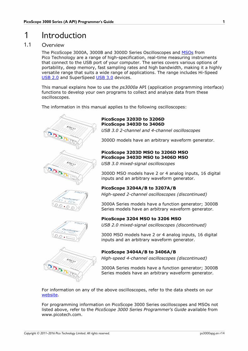
The information in this manual applies to the following oscilloscopes:
PicoScope 3203D to 3206DPicoScope 3403D to 3406D
USB 3.0 2-channel and 4-channel oscilloscopes
3000D models have an arbitrary waveform generator.
PicoScope 3203D MSO to 3206D MSOPicoScope 3403D MSO to 3406D MSO
USB 3.0 mixed-signal oscilloscopes
3000D MSO models have 2 or 4 analog inputs, 16 digitalinputs and an arbitrary waveform generator.
PicoScope 3204A/B to 3207A/B
High-speed 2-channel oscilloscopes (discontinued)
3000A Series models have a function generator; 3000BSeries models have an arbitrary waveform generator.
PicoScope 3204 MSO to 3206 MSO
USB 2.0 mixed-signal oscilloscopes (discontinued)
3000 MSO models have 2 or 4 analog inputs, 16 digitalinputs and an arbitrary waveform generator.
PicoScope 3404A/B to 3406A/B
High-speed 4-channel oscilloscopes (discontinued)
3000A Series models have a function generator; 3000BSeries models have an arbitrary waveform generator.
For information on any of the above oscilloscopes, refer to the data sheets on our website.
For programming information on PicoScope 3000 Series oscilloscopes and MSOs notlisted above, refer to the PicoScope 3000 Series Programmer's Guide available fromwww.picotech.com.
Introduction2
Copyright © 2011–2016 Pico Technology Limited. All rights reserved.ps3000apg.en r14
1.2 License agreementGrant of license. The material contained in this release is licensed, not sold. PicoTechnology Limited ('Pico') grants a license to the person who installs this software,subject to the conditions listed below.
Access. The licensee agrees to allow access to this software only to persons who havebeen informed of and agree to abide by these conditions.
Usage. The software in this release is for use only with Pico products or with datacollected using Pico products.
Copyright. The software in this release is for use only with Pico products or with datacollected using Pico products. You may copy and distribute the SDK without restriction,as long as you do not remove any Pico Technology copyright statements. The exampleprograms in the SDK may be modified, copied and distributed for the purpose ofdeveloping programs to collect data using Pico products.
Liability. Pico and its agents shall not be liable for any loss or damage, howsoevercaused, related to the use of Pico equipment or software, unless excluded by statute.
Fitness for purpose. No two applications are the same, so Pico cannot guaranteethat its equipment or software is suitable for a given application. It is therefore theuser's responsibility to ensure that the product is suitable for the user's application.
Mission-critical applications. Because the software runs on a computer that may berunning other software products, and may be subject to interference from these otherproducts, this license specifically excludes usage in 'mission-critical' applications, forexample life-support systems.
Viruses. This software was continuously monitored for viruses during production.However, the user is responsible for virus checking the software once it is installed.
Support. No software is ever error-free, but if you are dissatisfied with theperformance of this software, please contact our technical support staff.
Upgrades. We provide upgrades, free of charge, from our web site atwww.picotech.com. We reserve the right to charge for updates or replacements sentout on physical media.
1.3 TrademarksPico Technology and PicoScope are trademarks of Pico Technology Limited,registered in the United Kingdom and other countries.
PicoScope and Pico Technology are registered in the U.S. Patent and TrademarkOffice.
Windows and Visual Basic for Applications are registered trademarks ortrademarks of Microsoft Corporation in the USA and other countries.
PicoScope 3000 Series (A API) Programmer's Guide 3
Copyright © 2011–2016 Pico Technology Limited. All rights reserved. ps3000apg.en r14
2 Programming the PicoScope 3000 Series (A API)oscilloscopesThe ps3000a.dll dynamic link library (DLL) in the SDK allows you to program any
supported oscilloscope using standard C function calls.
A typical program for capturing data consists of the following steps:· Open the scope unit.· Set up the input channels with the required voltage ranges and coupling type.· Set up triggering.· Start capturing data. (See Sampling modes, where programming is discussed in
more detail.)· Wait until the scope unit is ready.· Stop capturing data.· Copy data to a buffer.· Close the scope unit.
Numerous example programs are included in the SDK. These demonstrate how to usethe functions of the driver software in each of the modes available.
2.1 DriversYour application communicates with two drivers—ps3000a.dll and picoipp.dll—
which are supplied in 32-bit and 64-bit versions. ps3000a.dll exports the ps3000a
function definitions in standard C format but this does not limit you to programming inC. You can use the API with any programming language that supports standard C calls.
The two DLLs depend on a low-level (kernel) driver called WinUsb.sys. This is installed
by the SDK and configured when you plug the oscilloscope into each USB port for thefirst time.
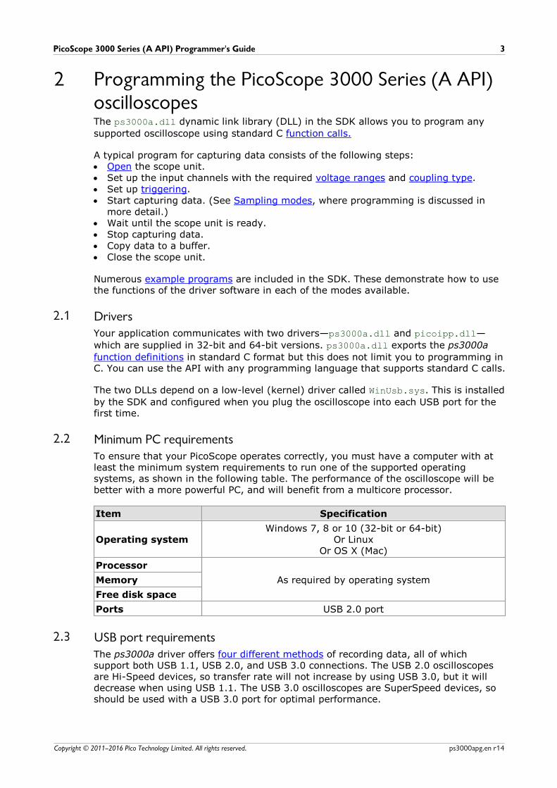
2.2 Minimum PC requirementsTo ensure that your PicoScope operates correctly, you must have a computer with atleast the minimum system requirements to run one of the supported operatingsystems, as shown in the following table. The performance of the oscilloscope will bebetter with a more powerful PC, and will benefit from a multicore processor.
Item Specification
Operating systemWindows 7, 8 or 10 (32-bit or 64-bit)
Or LinuxOr OS X (Mac)
Processor
As required by operating systemMemory
Free disk space
Ports USB 2.0 port
2.3 USB port requirementsThe ps3000a driver offers four different methods of recording data, all of whichsupport both USB 1.1, USB 2.0, and USB 3.0 connections. The USB 2.0 oscilloscopesare Hi-Speed devices, so transfer rate will not increase by using USB 3.0, but it willdecrease when using USB 1.1. The USB 3.0 oscilloscopes are SuperSpeed devices, soshould be used with a USB 3.0 port for optimal performance.
Device features4
Copyright © 2011–2016 Pico Technology Limited. All rights reserved.ps3000apg.en r14
3 Device features3.1 Power options
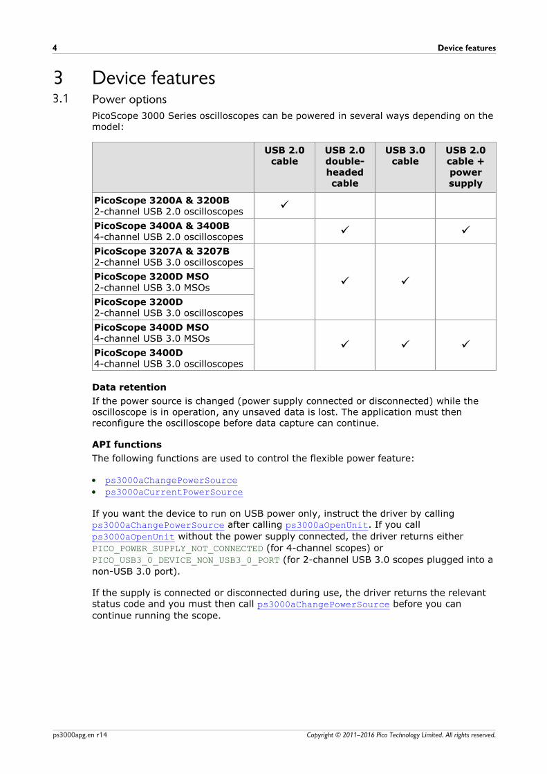
PicoScope 3000 Series oscilloscopes can be powered in several ways depending on themodel:
USB 2.0cable
USB 2.0double-headedcable
USB 3.0cable
USB 2.0cable +powersupply
PicoScope 3200A & 3200B2-channel USB 2.0 oscilloscopes
ü
PicoScope 3400A & 3400B 4-channel USB 2.0 oscilloscopes
ü ü
PicoScope 3207A & 3207B2-channel USB 3.0 oscilloscopes
ü üPicoScope 3200D MSO 2-channel USB 3.0 MSOs
PicoScope 3200D2-channel USB 3.0 oscilloscopes
PicoScope 3400D MSO4-channel USB 3.0 MSOs
ü ü üPicoScope 3400D4-channel USB 3.0 oscilloscopes
Data retention
If the power source is changed (power supply connected or disconnected) while theoscilloscope is in operation, any unsaved data is lost. The application must thenreconfigure the oscilloscope before data capture can continue.
API functions
The following functions are used to control the flexible power feature:
· ps3000aChangePowerSource
· ps3000aCurrentPowerSource
If you want the device to run on USB power only, instruct the driver by calling ps3000aChangePowerSource after calling ps3000aOpenUnit. If you call
ps3000aOpenUnit without the power supply connected, the driver returns either
PICO_POWER_SUPPLY_NOT_CONNECTED (for 4-channel scopes) or
PICO_USB3_0_DEVICE_NON_USB3_0_PORT (for 2-channel USB 3.0 scopes plugged into a
non-USB 3.0 port).
If the supply is connected or disconnected during use, the driver returns the relevantstatus code and you must then call ps3000aChangePowerSource before you can
continue running the scope.
PicoScope 3000 Series (A API) Programmer's Guide 5
Copyright © 2011–2016 Pico Technology Limited. All rights reserved. ps3000apg.en r14
3.2 Voltage rangesAnalog input channels
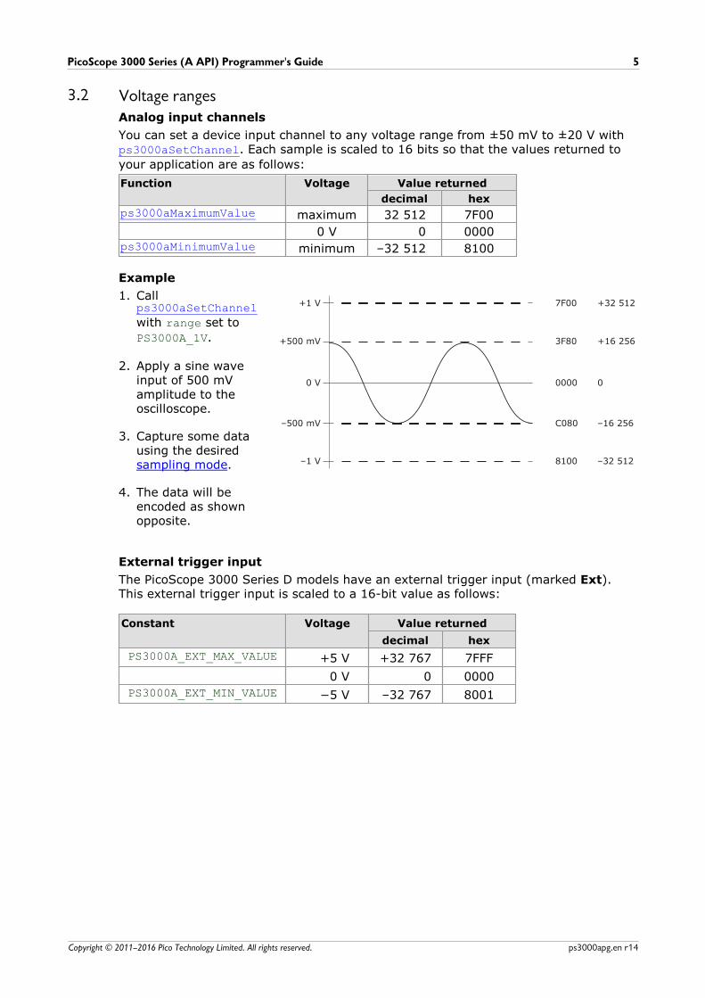
You can set a device input channel to any voltage range from ±50 mV to ±20 V withps3000aSetChannel. Each sample is scaled to 16 bits so that the values returned to
your application are as follows:
Function Voltage Value returned
decimal hex
ps3000aMaximumValue maximum 32 512 7F00
0 V 0 0000ps3000aMinimumValue minimum –32 512 8100
Example
1. Call ps3000aSetChannel
with range set to
PS3000A_1V.
2. Apply a sine waveinput of 500 mVamplitude to theoscilloscope.
3. Capture some datausing the desired sampling mode.
4. The data will beencoded as shownopposite.
External trigger input
The PicoScope 3000 Series D models have an external trigger input (marked Ext).This external trigger input is scaled to a 16-bit value as follows:
Constant Voltage Value returned
decimal hex
PS3000A_EXT_MAX_VALUE +5 V +32 767 7FFF
0 V 0 0000
PS3000A_EXT_MIN_VALUE –32 767 8001

Device features6
Copyright © 2011–2016 Pico Technology Limited. All rights reserved.ps3000apg.en r14
3.3 MSO digital dataApplicability: mixed-signal oscilloscope (MSO) devices only
A PicoScope MSO has two 8-bit digital ports—PORT0 and PORT1—making a total of 16digital channels.
The data from each port is returned in a separate buffer that is set up by the ps3000aSetDataBuffer and ps3000aSetDataBuffers functions. For compatibility with
the analog channels, each buffer is an array of 16-bit words. The 8-bit port dataoccupies the lower 8 bits of the word while the upper 8 bits of the word are undefined.
PORT1 buffer PORT0 buffer
Sample0 [XXXXXXXX,D15...D8]0 [XXXXXXXX,D7...D0]0
... ... ...
Samplen–1 [XXXXXXXX,D15...D8]n–1 [XXXXXXXX,D7...D0]n–1
Retrieving stored digital data
The following C code snippet shows how to combine data from the two 8-bit ports intoa single 16-bit word, and then how to extract individual bits from the 16-bit word.
// Mask Port 1 values to get lower 8 bitsportValue = 0x00ff & appDigiBuffers[2][i];
// Shift by 8 bits to place in upper 8 bits of 16-bit wordportValue <<= 8;
// Mask Port 0 values to get lower 8 bits,// then OR with shifted Port 1 bits to get 16-bit wordportValue |= 0x00ff & appDigiBuffers[0][i];
for (bit = 0; bit < 16; bit++){ // Shift value 32768 (binary 1000 0000 0000 0000). // AND with value to get 1 or 0 for channel. // Order will be D15 to D8, then D7 to D0.
bitValue = (0x8000 >> bit) & portValue? 1 : 0; }
PicoScope 3000 Series (A API) Programmer's Guide 7
Copyright © 2011–2016 Pico Technology Limited. All rights reserved. ps3000apg.en r14
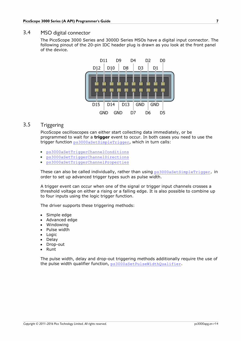
3.4 MSO digital connectorThe PicoScope 3000 Series and 3000D Series MSOs have a digital input connector. Thefollowing pinout of the 20-pin IDC header plug is drawn as you look at the front panelof the device.
3.5 TriggeringPicoScope oscilloscopes can either start collecting data immediately, or beprogrammed to wait for a trigger event to occur. In both cases you need to use thetrigger function ps3000aSetSimpleTrigger, which in turn calls:
· ps3000aSetTriggerChannelConditions
· ps3000aSetTriggerChannelDirections
· ps3000aSetTriggerChannelProperties
These can also be called individually, rather than using ps3000aSetSimpleTrigger, in
order to set up advanced trigger types such as pulse width.
A trigger event can occur when one of the signal or trigger input channels crosses athreshold voltage on either a rising or a falling edge. It is also possible to combine upto four inputs using the logic trigger function.
The driver supports these triggering methods:
· Simple edge· Advanced edge· Windowing· Pulse width· Logic· Delay· Drop-out· Runt
The pulse width, delay and drop-out triggering methods additionally require the use ofthe pulse width qualifier function, ps3000aSetPulseWidthQualifier.
Device features8
Copyright © 2011–2016 Pico Technology Limited. All rights reserved.ps3000apg.en r14
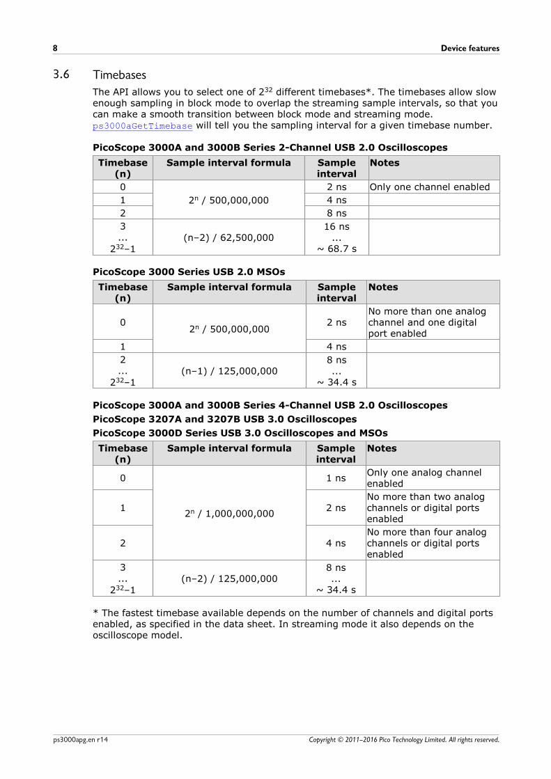
3.6 Timebases
The API allows you to select one of 232 different timebases*. The timebases allow slowenough sampling in block mode to overlap the streaming sample intervals, so that youcan make a smooth transition between block mode and streaming mode. ps3000aGetTimebase will tell you the sampling interval for a given timebase number.
PicoScope 3000A and 3000B Series 2-Channel USB 2.0 Oscilloscopes
Timebase(n)
Sample interval formula Sampleinterval
Notes
0
2n / 500,000,000
2 ns Only one channel enabled
1 4 ns
2 8 ns
3...
232–1(n–2) / 62,500,000
16 ns...
~ 68.7 s
PicoScope 3000 Series USB 2.0 MSOs
Timebase(n)
Sample interval formula Sampleinterval
Notes
02n / 500,000,000
2 nsNo more than one analogchannel and one digitalport enabled
1 4 ns
2...
232–1(n–1) / 125,000,000
8 ns...
~ 34.4 s
PicoScope 3000A and 3000B Series 4-Channel USB 2.0 Oscilloscopes
PicoScope 3207A and 3207B USB 3.0 Oscilloscopes
PicoScope 3000D Series USB 3.0 Oscilloscopes and MSOs
Timebase(n)
Sample interval formula Sampleinterval
Notes
0
2n / 1,000,000,000
1 nsOnly one analog channelenabled
1 2 nsNo more than two analogchannels or digital portsenabled
2 4 nsNo more than four analogchannels or digital portsenabled
3...
232–1(n–2) / 125,000,000
8 ns...
~ 34.4 s
* The fastest timebase available depends on the number of channels and digital portsenabled, as specified in the data sheet. In streaming mode it also depends on theoscilloscope model.
PicoScope 3000 Series (A API) Programmer's Guide 9
Copyright © 2011–2016 Pico Technology Limited. All rights reserved. ps3000apg.en r14
3.7 Sampling modesPicoScope oscilloscopes can run in various sampling modes:
· Block mode. In this mode, the scope stores data in its buffer memory and thentransfers it to the PC. When the data has been collected it is possible to examine thedata, with an optional downsampling factor. The data is lost when a new capture isstarted, the settings are changed, or the scope is powered down.
· ETS mode. In this mode, it is possible to increase the effective sampling rate of thescope when capturing repetitive signals. It is a modified form of block mode.
· Rapid block mode. This is a variant of block mode that allows you to capture morethan one waveform at a time with a minimum of delay between captures. You canuse downsampling in this mode if you wish.
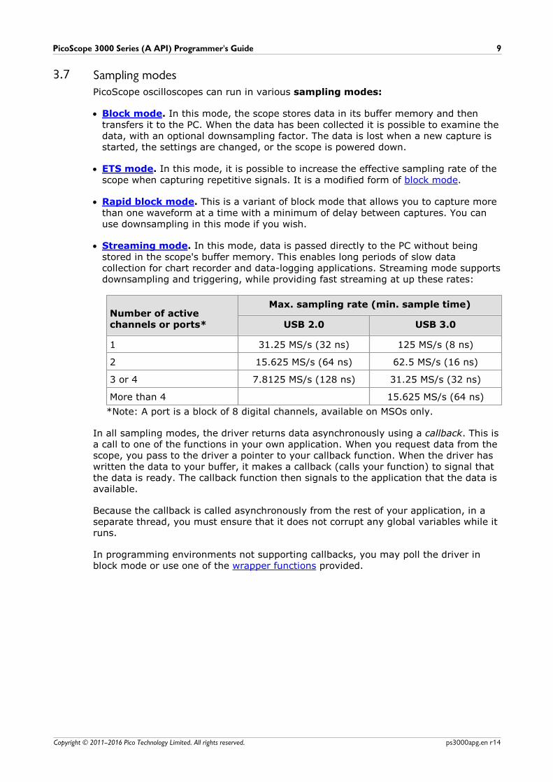
· Streaming mode. In this mode, data is passed directly to the PC without beingstored in the scope's buffer memory. This enables long periods of slow datacollection for chart recorder and data-logging applications. Streaming mode supportsdownsampling and triggering, while providing fast streaming at up these rates:
Number of activechannels or ports*
Max. sampling rate (min. sample time)
USB 2.0 USB 3.0
1 31.25 MS/s (32 ns) 125 MS/s (8 ns)
2 15.625 MS/s (64 ns) 62.5 MS/s (16 ns)
3 or 4 7.8125 MS/s (128 ns) 31.25 MS/s (32 ns)
More than 4 15.625 MS/s (64 ns)
*Note: A port is a block of 8 digital channels, available on MSOs only.
In all sampling modes, the driver returns data asynchronously using a callback. This isa call to one of the functions in your own application. When you request data from thescope, you pass to the driver a pointer to your callback function. When the driver haswritten the data to your buffer, it makes a callback (calls your function) to signal thatthe data is ready. The callback function then signals to the application that the data isavailable.
Because the callback is called asynchronously from the rest of your application, in aseparate thread, you must ensure that it does not corrupt any global variables while itruns.
In programming environments not supporting callbacks, you may poll the driver inblock mode or use one of the wrapper functions provided.
Device features10
Copyright © 2011–2016 Pico Technology Limited. All rights reserved.ps3000apg.en r14
3.7.1 Block mode
In block mode, the computer prompts the oscilloscope to collect a block of data intoits internal memory. When the oscilloscope has collected the whole block, it signalsthat it is ready and then transfers the whole block to the computer's memory throughthe USB port.
· Block size. The maximum number of values depends upon the size of theoscilloscope's memory. The memory buffer is shared between the enabled channels,so if two channels are enabled, each receives half the memory. If three or fourchannels are enabled, each receives a quarter of the memory. These calculationsare handled transparently by the driver. The block size also depends on the numberof memory segments in use (see ps3000aMemorySegments).
For the PicoScope 3000 and 3000D Series MSOs, the memory is shared betweenthe digital ports and analog channels. If one or more analog channels is enabled atthe same time as one or more digital ports, the memory per channel is one quarterof the buffer size.
· Sampling rate. A ps3000a oscilloscope can sample at a number of different ratesaccording to the selected timebase and the combination of channels that areenabled. See the PicoScope 3000 Series Data Sheet for the specifications that applyto your scope model.
· Setup time. The driver normally performs a number of setup operations, which cantake up to 50 milliseconds, before collecting each block of data. If you need tocollect data with the minimum time interval between blocks, use rapid block modeand avoid calling setup functions between calls to ps3000aRunBlock, ps3000aStop
and ps3000aGetValues.
· Downsampling. When the data has been collected, you can set an optionaldownsampling factor and examine the data. Downsampling is a process thatreduces the amount of data by combining adjacent samples. It is useful for zoomingin and out of the data without having to repeatedly transfer the entire contents ofthe scope's buffer to the PC.
· Memory segmentation. The scope's internal memory can be divided intosegments so that you can capture several waveforms in succession. Configure thisusing ps3000aMemorySegments.
· Data retention. The data is lost when a new run is started in the same segment,the settings are changed, or the scope is powered down or the power source ischanged (for flexible power devices).
See Using block mode for programming details.

PicoScope 3000 Series (A API) Programmer's Guide 11
Copyright © 2011–2016 Pico Technology Limited. All rights reserved. ps3000apg.en r14
3.7.1.1 Using block mode
This is the general procedure for reading and displaying data in block mode using asingle memory segment:
1. Open the oscilloscope using ps3000aOpenUnit.
2. Select channel ranges and AC/DC coupling using ps3000aSetChannel. All
channels are enabled by default, so if you wish to allocate the buffer memory tofewer channels you must disable those that are not required.
3. [MSOs only] Set the digital port using ps3000aSetDigitalPort.
4. Using ps3000aGetTimebase, select timebases until the required number of
nanoseconds per sample is located.5. Use the trigger setup functions ps3000aSetTriggerChannelConditionsV2,
ps3000aSetTriggerChannelDirections and
ps3000aSetTriggerChannelProperties to set up the trigger if required.
6. [MSOs only] Use the trigger setup functionsps3000aSetTriggerDigitalPortProperties to set up the digital trigger if
required.7. Start the oscilloscope running using ps3000aRunBlock.
8. Wait until the oscilloscope is ready using the ps3000aBlockReady callback (or
poll using ps3000aIsReady).
9. Use ps3000aSetDataBuffer to tell the driver where your memory buffer is. For
greater efficiency when doing multiple captures, you can call this functionoutside the loop, after step 6.
10. Transfer the block of data from the oscilloscope using ps3000aGetValues.
11. Display the data.12. Repeat steps 7 to 11.13. Stop the oscilloscope using ps3000aStop.
14. Request new views of stored data using different downsampling parameters:see Retrieving stored data.
15. Close the oscilloscope using ps3000aCloseUnit.

Device features12
Copyright © 2011–2016 Pico Technology Limited. All rights reserved.ps3000apg.en r14
3.7.1.2 Asynchronous calls in block mode
ps3000aGetValues may take a long time to complete if a large amount of data is
being collected. For example, it can take several seconds to retrieve the full 512 Msamples from a PicoScope 3206D using a USB 3.0 connection, or several minutes onUSB 1.1. To avoid hanging the calling thread, it is possible to call ps3000aGetValuesAsync instead. This immediately returns control to the calling
thread, which then has the option of waiting for the data or calling ps3000aStop to
abort the operation.
PicoScope 3000 Series (A API) Programmer's Guide 13
Copyright © 2011–2016 Pico Technology Limited. All rights reserved. ps3000apg.en r14
3.7.2 Rapid block mode
In normal block mode, the oscilloscope collects one waveform at a time. You start thethe device running, wait until all samples are collected by the device, and thendownload the data to the PC or start another run. There is a time overhead of tens ofmilliseconds associated with starting a run, causing a gap between waveforms. Whenyou collect data from the device, there is another minimum time overhead which ismost noticeable when using a small number of samples.
Rapid block mode allows you to sample several waveforms at a time with theminimum time between waveforms. It reduces the gap from milliseconds to less than2 microseconds (on fastest timebase).
See Using rapid block mode for details.
3.7.2.1 Using rapid block mode
You can use rapid block mode with or without aggregation. With aggregation, youneed to set up two buffers for each channel to receive the minimum and maximumvalues.
Without aggregation
1. Open the oscilloscope using ps3000aOpenUnit.
2. Select channel ranges and AC/DC coupling using ps3000aSetChannel.
3. [MSOs only] Set the digital port using ps3000aSetDigitalPort.
4. Set the number of memory segments equal to or greater than the number ofcaptures required using ps3000aMemorySegments. Use ps3000aSetNoOfCaptures
before each run to specify the number of waveforms to capture.5. Using ps3000aGetTimebase, select timebases until the required sampling
interval is located. The function will indicate the number of samples per channelavailable for each segment. If you do not need to know the segment size limit(because you are capturing a small number of samples) you can optionally callthis function before step 4.
6. Use the trigger setup functions ps3000aSetTriggerChannelConditionsV2,
ps3000aSetTriggerChannelDirections and
ps3000aSetTriggerChannelProperties to set up the trigger if required.
7. [MSOs only] Use the trigger setup functionsps3000aSetTriggerDigitalPortProperties to set up the digital trigger if
required.8. Start the oscilloscope running using ps3000aRunBlock.
9. Wait until the oscilloscope is ready using the ps3000aIsReady or wait on the
callback function.10. Use ps3000aSetDataBuffer to tell the driver where your memory buffers are.
Call the function once for each channel/segment combination for which yourequire data. For greater efficiency when doing multiple captures, you can callthis function outside the loop, after step 7.
11. Transfer the blocks of data from the oscilloscope using ps3000aGetValuesBulk.
12. Retrieve the time offset for each data segment usingps3000aGetValuesTriggerTimeOffsetBulk64.
13. Display the data.14. Repeat steps 8 to 13 if necessary.15. Stop the oscilloscope using ps3000aStop.
16. Close the oscilloscope using ps3000aCloseUnit.

Device features14
Copyright © 2011–2016 Pico Technology Limited. All rights reserved.ps3000apg.en r14
With aggregation
To use rapid block mode with aggregation, follow steps 1 to 9 above, then proceed asfollows:
10a. Call ps3000aSetDataBuffer or (ps3000aSetDataBuffers) to set up one pair of
buffers for every waveform segment required.11a. Call ps3000aGetValuesBulk for each pair of buffers.
12a. Retrieve the time offset for each data segment usingps3000aGetValuesTriggerTimeOffsetBulk64.
Continue from step 13 above.

PicoScope 3000 Series (A API) Programmer's Guide 15
Copyright © 2011–2016 Pico Technology Limited. All rights reserved. ps3000apg.en r14
3.7.2.2 Rapid block mode example 1: no aggregation
#define MAX_SAMPLES 1000
Set up the device up as usual.
· Open the device· Channels· Trigger· Number of memory segments (this should be equal or more than the number of
captures required)
// Set the number of waveforms to 100ps3000aSetNoOfCaptures(handle, 100);
pParameter = false;
ps3000aRunBlock( handle, 0, // noOfPreTriggerSamples 10000, // noOfPostTriggerSamples 1, // timebase to be used 1, // not used &timeIndisposedMs, 0, // segment index lpReady, &pParameter );
Comment: these variables have been set as an example and can be any valid value. pParameter will be set true by your callback function lpReady.
while (!pParameter) Sleep (0);
for (int32_t i = 0; i < 10; i++){
for (int32_t c = PS3000A_CHANNEL_A; c <= PS3000A_CHANNEL_B; c++){
ps3000aSetDataBuffer(
handle,c,buffer[c][i],MAX_SAMPLES,i
PS3000A_RATIO_MODE_NONE);
}}
Comments: buffer has been created as a two-dimensional array of pointers to int16_t, which will contain 1000 samples as defined by MAX_SAMPLES. There are only
10 buffers set, but it is possible to set up to the number of captures you haverequested.
Device features16
Copyright © 2011–2016 Pico Technology Limited. All rights reserved.ps3000apg.en r14
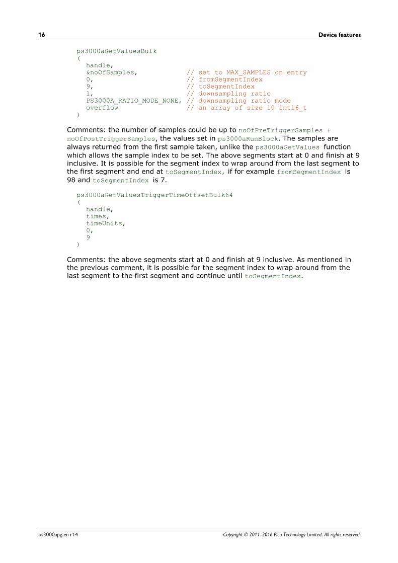
ps3000aGetValuesBulk(
handle,&noOfSamples, // set to MAX_SAMPLES on entry0, // fromSegmentIndex9, // toSegmentIndex1, // downsampling ratioPS3000A_RATIO_MODE_NONE, // downsampling ratio modeoverflow // an array of size 10 int16_t
)
Comments: the number of samples could be up to noOfPreTriggerSamples +
noOfPostTriggerSamples, the values set in ps3000aRunBlock. The samples are
always returned from the first sample taken, unlike the ps3000aGetValues function
which allows the sample index to be set. The above segments start at 0 and finish at 9inclusive. It is possible for the segment index to wrap around from the last segment tothe first segment and end at toSegmentIndex, if for example fromSegmentIndex is
98 and toSegmentIndex is 7.
ps3000aGetValuesTriggerTimeOffsetBulk64(
handle,times,timeUnits,0,9
)
Comments: the above segments start at 0 and finish at 9 inclusive. As mentioned inthe previous comment, it is possible for the segment index to wrap around from thelast segment to the first segment and continue until toSegmentIndex.
PicoScope 3000 Series (A API) Programmer's Guide 17
Copyright © 2011–2016 Pico Technology Limited. All rights reserved. ps3000apg.en r14
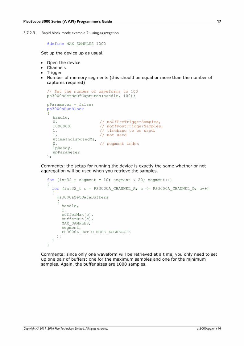
3.7.2.3 Rapid block mode example 2: using aggregation
#define MAX_SAMPLES 1000
Set up the device up as usual.
· Open the device· Channels· Trigger· Number of memory segments (this should be equal or more than the number of
captures required)
// Set the number of waveforms to 100ps3000aSetNoOfCaptures(handle, 100);
pParameter = false;ps3000aRunBlock(
handle,0, // noOfPreTriggerSamples,1000000, // noOfPostTriggerSamples,1, // timebase to be used,1, // not used&timeIndisposedMs,0, // segment indexlpReady,&pParameter
);
Comments: the setup for running the device is exactly the same whether or notaggregation will be used when you retrieve the samples.
for (int32_t segment = 10; segment < 20; segment++){ for (int32_t c = PS3000A_CHANNEL_A; c <= PS3000A_CHANNEL_D; c++) { ps3000aSetDataBuffers ( handle, c, bufferMax[c], bufferMin[c], MAX_SAMPLES, segment, PS3000A_RATIO_MODE_AGGREGATE ); }}
Comments: since only one waveform will be retrieved at a time, you only need to setup one pair of buffers; one for the maximum samples and one for the minimumsamples. Again, the buffer sizes are 1000 samples.
Device features18
Copyright © 2011–2016 Pico Technology Limited. All rights reserved.ps3000apg.en r14
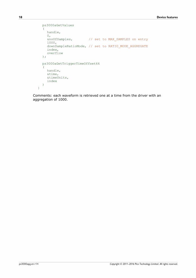
ps3000aGetValues(
handle,0,&noOfSamples, // set to MAX_SAMPLES on entry1000, downSampleRatioMode, // set to RATIO_MODE_AGGREGATEindex,overflow
);
ps3000aGetTriggerTimeOffset64(
handle,&time,&timeUnits,index
)}
Comments: each waveform is retrieved one at a time from the driver with anaggregation of 1000.

PicoScope 3000 Series (A API) Programmer's Guide 19
Copyright © 2011–2016 Pico Technology Limited. All rights reserved. ps3000apg.en r14
3.7.3 ETS (Equivalent Time Sampling)
ETS is a way of increasing the effective sampling rate of the scope when capturingrepetitive signals. It is a modified form of block mode, and is controlled by the triggerfunctions and ps3000aSetEts.
Overview: ETS works by capturing several cycles of a repetitive waveform, thencombining them to produce a composite waveform that has a higher effective samplingrate than the individual captures. The result is a larger set of samples spaced by asmall fraction of the original sampling interval. The maximum effective sampling ratesthat can be achieved with this method are listed in the User's Guide for the scopedevice.
Trigger stability: Because of the high sensitivity of ETS mode to small timedifferences, the trigger must be set up to provide a stable waveform that varies aslittle as possible from one capture to the next.
Callback: ETS mode calls the ps3000aBlockReady callback function when a new
waveform is ready for collection. Your application should then call ps3000aGetValues
to retrieve the waveform from the data buffer and the sample times from the ETStimes buffer.
Applicability Available in block mode only.Not suitable for one-shot (non-repetitive) signals.Aggregation is not supported.Edge-triggering only.Auto trigger delay (autoTriggerMilliseconds) is ignored.
Digital ports (on MSOs) cannot be used in ETS mode.Refer to product specifications for availability of ETS triggering onspecific devices.

Device features20
Copyright © 2011–2016 Pico Technology Limited. All rights reserved.ps3000apg.en r14
3.7.3.1 Using ETS mode
This is the general procedure for reading and displaying data in ETS mode using asingle memory segment:
When using ETS mode you must consider if a digital port has previously been active. Ifit has, call ps3000aSetDigitalPort and ps3000aSetTriggerDigitalPortProperties
to ensure these are not active when using ETS.
1. Open the oscilloscope using ps3000aOpenUnit.
2. Select channel ranges and AC/DC coupling using ps3000aSetChannel.
3. Use ps3000aSetEts to enable ETS and set the parameters.
4. Use ps3000aGetTimebase to verify the number of samples to be collected.
5. Use the trigger setup functions ps3000aSetTriggerChannelConditionsV2,
ps3000aSetTriggerChannelDirections and
ps3000aSetTriggerChannelProperties to set up the trigger if required.
6. Start the oscilloscope running using ps3000aRunBlock.
7. Wait until the oscilloscope is ready using the ps3000aBlockReady callback (or poll
using ps3000aIsReady).
8. Use ps3000aSetDataBuffer to tell the driver where your memory buffer is.
8a. Use ps3000aSetEtsTimeBuffer or ps3000aSetEtsTimeBuffers to tell the driver
where to store the sample times.9. Transfer the block of data from the oscilloscope using ps3000aGetValues.
10. Display the data.11. While you want to collect updated captures, repeat steps 7 to 10.12. Repeat steps 6 to 11.13. Stop the oscilloscope using ps3000aStop.
14. Close the oscilloscope using ps3000aCloseUnit.
PicoScope 3000 Series (A API) Programmer's Guide 21
Copyright © 2011–2016 Pico Technology Limited. All rights reserved. ps3000apg.en r14
3.7.4 Streaming mode
Streaming mode can capture data without the gaps that occur between blocks whenusing block mode. Streaming mode supports downsampling and triggering, whileproviding fast streaming (for example, with USB 2.0, at up to 31.25 MS/s or 32 ns persample) when one channel is active, depending on the computer's performance. Thismakes it suitable for high-speed data acquisition, allowing you to capture long datasets limited only by the computer's memory.
· Aggregation. The driver returns aggregated readings while the device is streaming.If aggregation is set to 1 then only one buffer is used per channel. When aggregationis set above 1 then two buffers (maximum and minimum) per channel are used.
· Memory segmentation. The memory can be divided into segments to reduce thelatency of data transfers to the PC. However, this increases the risk of losing data ifthe PC cannot keep up with the device's sampling rate.
See Using streaming mode for programming details when using the API. When usingthe wrapper DLL, see Using the wrapper functions for streaming data capture.
Device features22
Copyright © 2011–2016 Pico Technology Limited. All rights reserved.ps3000apg.en r14
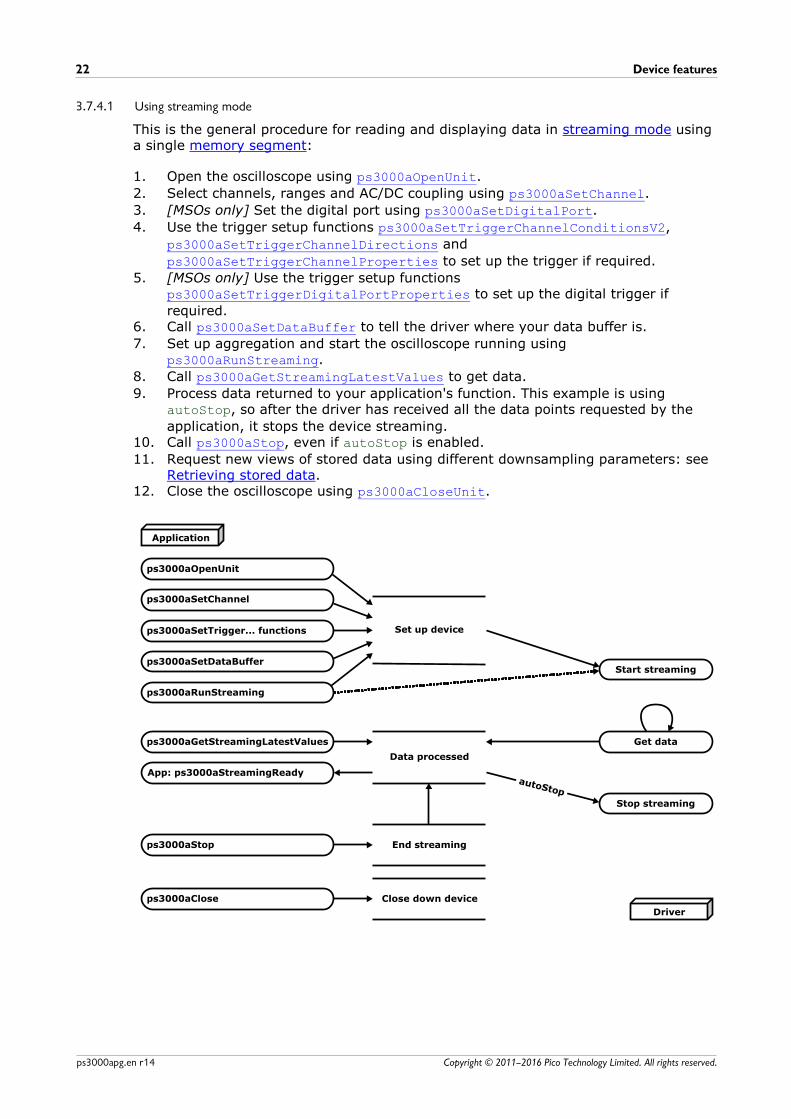
3.7.4.1 Using streaming mode
This is the general procedure for reading and displaying data in streaming mode usinga single memory segment:
1. Open the oscilloscope using ps3000aOpenUnit.
2. Select channels, ranges and AC/DC coupling using ps3000aSetChannel.
3. [MSOs only] Set the digital port using ps3000aSetDigitalPort.
4. Use the trigger setup functions ps3000aSetTriggerChannelConditionsV2,
ps3000aSetTriggerChannelDirections and
ps3000aSetTriggerChannelProperties to set up the trigger if required.
5. [MSOs only] Use the trigger setup functionsps3000aSetTriggerDigitalPortProperties to set up the digital trigger if
required.6. Call ps3000aSetDataBuffer to tell the driver where your data buffer is.
7. Set up aggregation and start the oscilloscope running usingps3000aRunStreaming.
8. Call ps3000aGetStreamingLatestValues to get data.
9. Process data returned to your application's function. This example is usingautoStop, so after the driver has received all the data points requested by the
application, it stops the device streaming.10. Call ps3000aStop, even if autoStop is enabled.
11. Request new views of stored data using different downsampling parameters: seeRetrieving stored data.
12. Close the oscilloscope using ps3000aCloseUnit.
PicoScope 3000 Series (A API) Programmer's Guide 23
Copyright © 2011–2016 Pico Technology Limited. All rights reserved. ps3000apg.en r14
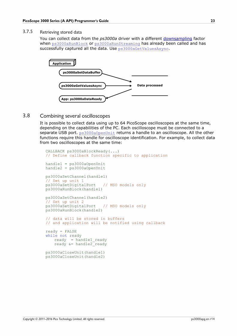
3.7.5 Retrieving stored data
You can collect data from the ps3000a driver with a different downsampling factorwhen ps3000aRunBlock or ps3000aRunStreaming has already been called and has
successfully captured all the data. Use ps3000aGetValuesAsync.
3.8 Combining several oscilloscopesIt is possible to collect data using up to 64 PicoScope oscilloscopes at the same time,depending on the capabilities of the PC. Each oscilloscope must be connected to aseparate USB port. ps3000aOpenUnit returns a handle to an oscilloscope. All the other
functions require this handle for oscilloscope identification. For example, to collect datafrom two oscilloscopes at the same time:
CALLBACK ps3000aBlockReady(...)// Define callback function specific to application
handle1 = ps3000aOpenUnithandle2 = ps3000aOpenUnit
ps3000aSetChannel(handle1)// Set up unit 1ps3000aSetDigitalPort // MSO models onlyps3000aRunBlock(handle1)
ps3000aSetChannel(handle2)// Set up unit 2ps3000aSetDigitalPort // MSO models only ps3000aRunBlock(handle2)
// data will be stored in buffers // and application will be notified using callback
ready = FALSEwhile not ready
ready = handle1_readyready &= handle2_ready
ps3000aCloseUnit(handle1)ps3000aCloseUnit(handle2)

API functions24
Copyright © 2011–2016 Pico Technology Limited. All rights reserved.ps3000apg.en r14
4 API functionsThe ps3000a API exports the following functions for you to use in your ownapplications. All functions are C functions using the standard call naming convention(__stdcall). They are all exported with both decorated and undecorated names. An
additional set of wrapper functions is provided for use with programming languagesthat do not support callbacks.
ps3000aBlockReady indicate when block-mode data readyps3000aChangePowerSource configure the unit's power sourceps3000aCloseUnit close a scope deviceps3000aCurrentPowerSource indicate the current power state of the deviceps3000aDataReady indicate when post-collection data readyps3000aEnumerateUnits find all connected oscilloscopesps3000aFlashLed flash the front-panel LEDps3000aGetAnalogueOffset query the permitted analog offset rangeps3000aGetChannelInformation query which ranges are available on a deviceps3000aGetMaxDownSampleRatio query the aggregation ratio for dataps3000aGetMaxEtsValues obtain limits for the ETS parametersps3000aGetMaxSegments query the maximum number of segmentsps3000aGetNoOfCaptures find out how many captures are availableps3000aGetNoOfProcessedCaptures query number of captures processedps3000aGetStreamingLatestValues get streaming data while scope is runningps3000aGetTimebase find out what timebases are availableps3000aGetTimebase2 find out what timebases are availableps3000aGetTriggerInfoBulk get rapid block trigger timingsps3000aGetTriggerTimeOffset find out when trigger occurred (32-bit)ps3000aGetTriggerTimeOffset64 find out when trigger occurred (64-bit)ps3000aGetUnitInfo read information about scope deviceps3000aGetValues retrieve block-mode data with callbackps3000aGetValuesAsync retrieve streaming data with callbackps3000aGetValuesBulk retrieve data in rapid block modeps3000aGetValuesOverlapped set up data collection ahead of captureps3000aGetValuesOverlappedBulk set up data collection in rapid block modeps3000aGetValuesTriggerTimeOffsetBulk get rapid-block waveform timings (32-bit)ps3000aGetValuesTriggerTimeOffsetBulk64 get rapid-block waveform timings (64-bit)ps3000aHoldOff not currently usedps3000aIsReady poll driver in block modeps3000aIsTriggerOrPulseWidthQualifierEnabled find out whether trigger is enabledps3000aMaximumValue query the max. ADC count in GetValues callsps3000aMemorySegments divide scope memory into segmentsps3000aMinimumValue query the min. ADC count in GetValues callsps3000aNoOfStreamingValues get number of samples in streaming modeps3000aOpenUnit open a scope deviceps3000aOpenUnitAsync open a scope device without waitingps3000aOpenUnitProgress check progress of OpenUnit callps3000aPingUnit check communication with device
ps3000aQueryOutputEdgeDetect query the output edge detect mode
ps3000aRunBlock start block modeps3000aRunStreaming start streaming modeps3000aSetBandwidthFilter control the bandwidth limiterps3000aSetChannel set up input channelsps3000aSetDataBuffer register data buffer with driverps3000aSetDataBuffers register aggregated data buffers with driverps3000aSetDigitalPort enable the digital port and set the logic levelps3000aSetEts set up equivalent-time samplingps3000aSetEtsTimeBuffer set up buffer for ETS timings (64-bit)ps3000aSetEtsTimeBuffers set up buffer for ETS timings (32-bit)ps3000aSetNoOfCaptures set number of captures to collect in one run
ps3000aSetOutputEdgeDetect switch output edge detect mode on or off
ps3000aSetPulseWidthDigitalPortProperties set up pulse width triggering on digital portps3000aSetPulseWidthQualifier set up pulse width triggeringps3000aSetPulseWidthQualifierV2 set up pulse width triggering (digital condition)

PicoScope 3000 Series (A API) Programmer's Guide 25
Copyright © 2011–2016 Pico Technology Limited. All rights reserved. ps3000apg.en r14
ps3000aSetSigGenArbitrary set up arbitrary waveform generatorps3000aSetSigGenBuiltIn set up standard signal generatorps3000aSetSigGenBuiltInV2 set up signal generator (double precision)ps3000aSetSigGenPropertiesArbitrary set arbitrary waveform generator propertiesps3000aSetSigGenPropertiesBuiltIn set signal generator propertiesps3000aSetSimpleTrigger set up level triggers onlyps3000aSetTriggerChannelConditions specify which channels to trigger onps3000aSetTriggerChannelConditionsV2 specify trigger channels for MSOsps3000aSetTriggerChannelDirections set up signal polarities for triggeringps3000aSetTriggerChannelProperties set up trigger thresholdsps3000aSetTriggerDelay set up post-trigger delayps3000aSetTriggerDigitalPortProperties set individual digital channels trigger directionsps3000aSigGenArbitraryMinMaxValues query AWG parameter limitsps3000aSigGenFrequencyToPhase calculate AWG phase from frequencyps3000aSigGenSoftwareControl trigger the signal generatorps3000aStop stop data captureps3000aStreamingReady indicate when streaming-mode data ready
API functions26
Copyright © 2011–2016 Pico Technology Limited. All rights reserved.ps3000apg.en r14
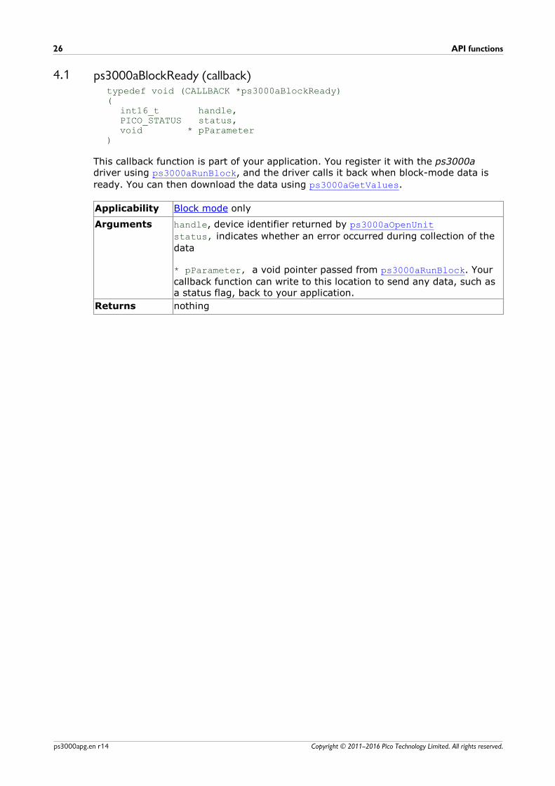
4.1 ps3000aBlockReady (callback)typedef void (CALLBACK *ps3000aBlockReady)(
int16_t handle,PICO_STATUS status,void * pParameter
)
This callback function is part of your application. You register it with the ps3000adriver using ps3000aRunBlock, and the driver calls it back when block-mode data is
ready. You can then download the data using ps3000aGetValues.
Applicability Block mode only
Arguments handle, device identifier returned by ps3000aOpenUnit
status, indicates whether an error occurred during collection of the
data
* pParameter, a void pointer passed from ps3000aRunBlock. Your
callback function can write to this location to send any data, such asa status flag, back to your application.
Returns nothing

PicoScope 3000 Series (A API) Programmer's Guide 27
Copyright © 2011–2016 Pico Technology Limited. All rights reserved. ps3000apg.en r14
4.2 ps3000aChangePowerSourcePICO_STATUS ps3000aChangePowerSource(
int16_t handle,PICO_STATUS powerstate
)
This function selects the power supply mode. You must call this function if any of thefollowing conditions arises:
· USB power is required· The power supply is connected or disconnected during use· A 2-channel USB 3.0 scope is plugged into a USB 2.0 port (indicated if any function
returns the PICO_USB3_0_DEVICE_NON_USB3_0_PORT status code)
Whenever the power supply mode is changed, all data and settings in the scope deviceare lost. You must then reconfigure the device before restarting capture.
Applicability All modes. 4-channel and USB 3.0 oscilloscopes only.
Arguments handle, device identifier returned by ps3000aOpenUnit
powerstate, the required state of the unit. One of the following:
PICO_POWER_SUPPLY_CONNECTED – to use power from the external
power supplyPICO_POWER_SUPPLY_NOT_CONNECTED – to use power from the USB
portPICO_USB3_0_DEVICE_NON_USB3_0_PORT – to use power from a
non-USB 3.0 port
Returns PICO_OKPICO_POWER_SUPPLY_REQUEST_INVALIDPICO_INVALID_PARAMETERPICO_NOT_RESPONDINGPICO_INVALID_HANDLE

API functions28
Copyright © 2011–2016 Pico Technology Limited. All rights reserved.ps3000apg.en r14
4.3 ps3000aCloseUnitPICO_STATUS ps3000aCloseUnit(
int16_t handle)
This function shuts down an oscilloscope.
Applicability All modes
Arguments handle, the device identifier, returned by ps3000aOpenUnit, of the
scope device to be closed
Returns PICO_OKPICO_HANDLE_INVALIDPICO_USER_CALLBACKPICO_DRIVER_FUNCTION

PicoScope 3000 Series (A API) Programmer's Guide 29
Copyright © 2011–2016 Pico Technology Limited. All rights reserved. ps3000apg.en r14
4.4 ps3000aCurrentPowerSourcePICO_STATUS ps3000aCurrentPowerSource(
int16_t handle)
This function returns the current power state of a 4-channel device. If called for a 2-channel device, it always returns PICO_OK.
Applicability All modes. Intended for for 4-channel devices.
Arguments handle, device identifier returned by ps3000aOpenUnit
Returns PICO_POWER_SUPPLY_CONNECTED – the device is powered by the
external power supplyPICO_POWER_SUPPLY_NOT_CONNECTED – the device is powered by the
USB portPICO_OK – the device has 2 channels

API functions30
Copyright © 2011–2016 Pico Technology Limited. All rights reserved.ps3000apg.en r14
4.5 ps3000aDataReady (callback)typedef void (CALLBACK *ps3000aDataReady)(
int16_t handle,PICO_STATUS status,uint32_t noOfSamples,int16_t overflow,void * pParameter
)
This is a callback function that you write to collect data from the driver. You supply apointer to the function when you call ps3000aGetValuesAsync, and the driver calls
your function back when the data is ready.
Applicability All modes
Arguments handle, device identifier returned by ps3000aOpenUnit
status, a PICO_STATUS code returned by the driver
noOfSamples, the number of samples collected
overflow, a set of flags that indicates whether an overvoltage has
occurred and on which channels. It is a bit field with bit 0representing Channel A.
* pParameter, a void pointer passed from ps3000aGetValuesAsync.
The callback function can write to this location to send any data, suchas a status flag, back to the application. The data type is defined bythe application programmer.
Returns nothing
PicoScope 3000 Series (A API) Programmer's Guide 31
Copyright © 2011–2016 Pico Technology Limited. All rights reserved. ps3000apg.en r14
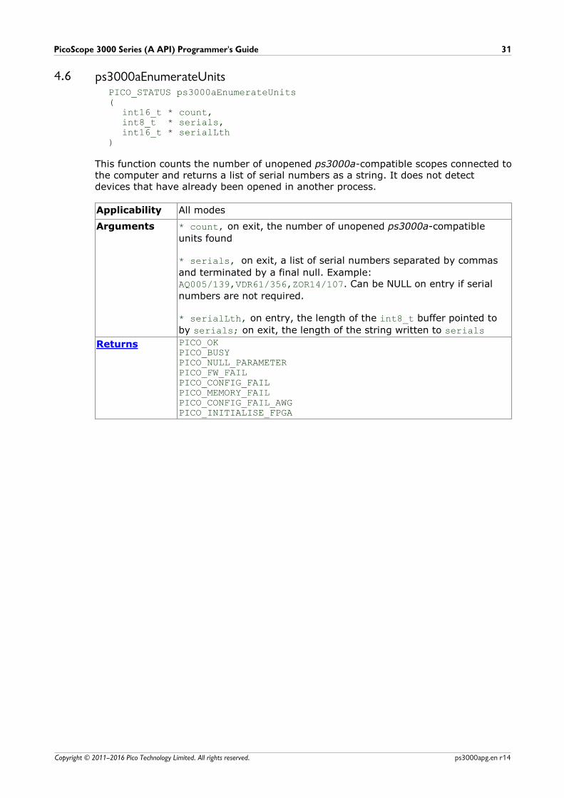
4.6 ps3000aEnumerateUnitsPICO_STATUS ps3000aEnumerateUnits(
int16_t * count,int8_t * serials,int16_t * serialLth
)
This function counts the number of unopened ps3000a-compatible scopes connected tothe computer and returns a list of serial numbers as a string. It does not detectdevices that have already been opened in another process.
Applicability All modes
Arguments * count, on exit, the number of unopened ps3000a-compatible
units found
* serials, on exit, a list of serial numbers separated by commas
and terminated by a final null. Example: AQ005/139,VDR61/356,ZOR14/107. Can be NULL on entry if serial
numbers are not required.
* serialLth, on entry, the length of the int8_t buffer pointed to
by serials; on exit, the length of the string written to serials
Returns PICO_OKPICO_BUSYPICO_NULL_PARAMETERPICO_FW_FAILPICO_CONFIG_FAILPICO_MEMORY_FAILPICO_CONFIG_FAIL_AWGPICO_INITIALISE_FPGA

API functions32
Copyright © 2011–2016 Pico Technology Limited. All rights reserved.ps3000apg.en r14
4.7 ps3000aFlashLedPICO_STATUS ps3000aFlashLed(
int16_t handle,int16_t start
)
This function flashes the LED on the front of the scope without blocking the callingthread. Calls to ps3000aRunStreaming and ps3000aRunBlock cancel any flashing
started by this function. It is not possible to set the LED to be constantly illuminated,as this state is used to indicate that the scope has not been initialized.
Applicability All modes
Arguments handle, device identifier returned by ps3000aOpenUnit
start, the action required: -
< 0 : flash the LED indefinitely.0 : stop the LED flashing.> 0 : flash the LED start times. If the LED is already flashing
on entry to this function, the flash count will be reset to start.
Returns PICO_OK PICO_HANDLE_INVALIDPICO_BUSYPICO_DRIVER_FUNCTIONPICO_NOT_RESPONDING
PicoScope 3000 Series (A API) Programmer's Guide 33
Copyright © 2011–2016 Pico Technology Limited. All rights reserved. ps3000apg.en r14
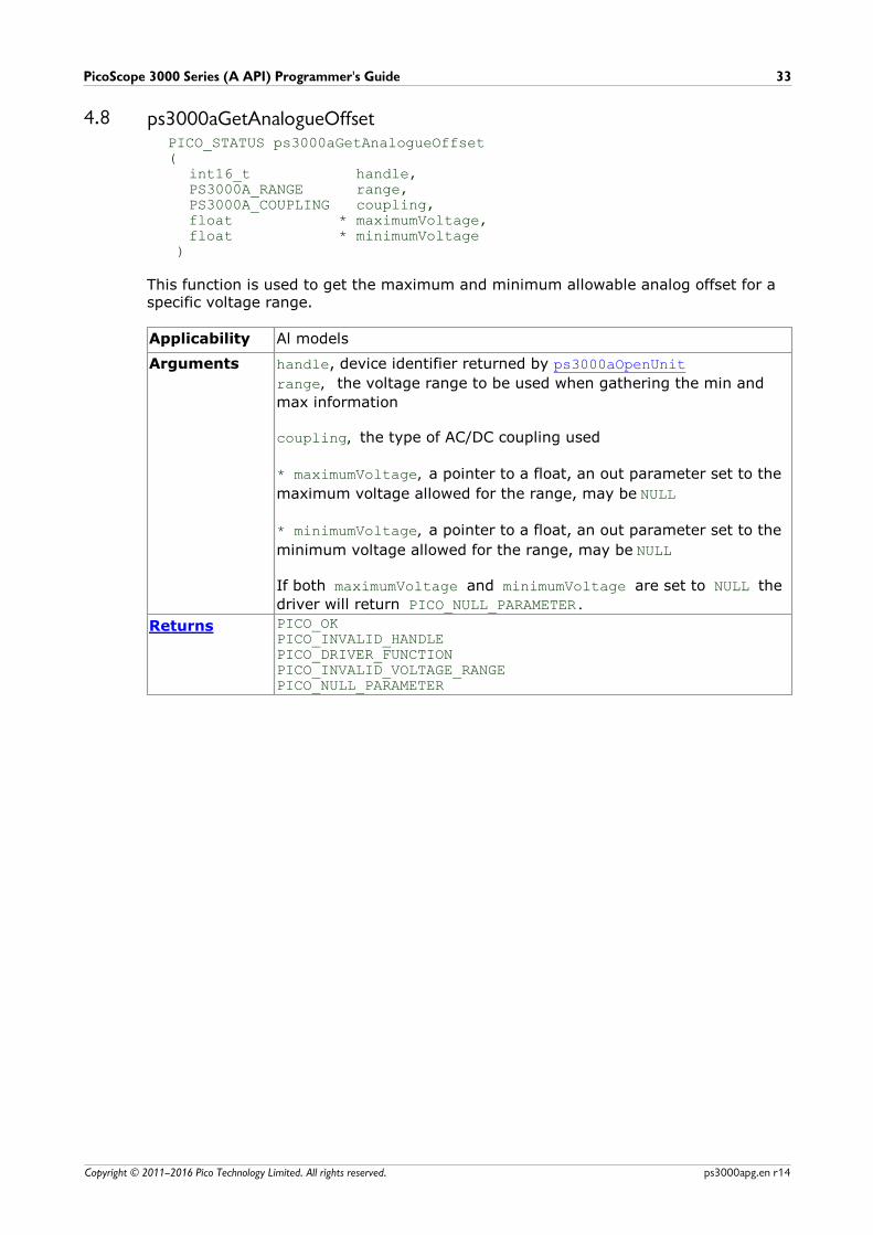
4.8 ps3000aGetAnalogueOffsetPICO_STATUS ps3000aGetAnalogueOffset(
int16_t handle,PS3000A_RANGE range,PS3000A_COUPLING coupling,float * maximumVoltage,float * minimumVoltage
)
This function is used to get the maximum and minimum allowable analog offset for aspecific voltage range.
Applicability Al models
Arguments handle, device identifier returned by ps3000aOpenUnit
range, the voltage range to be used when gathering the min and
max information
coupling, the type of AC/DC coupling used
* maximumVoltage, a pointer to a float, an out parameter set to the
maximum voltage allowed for the range, may be NULL
* minimumVoltage, a pointer to a float, an out parameter set to the
minimum voltage allowed for the range, may be NULL
If both maximumVoltage and minimumVoltage are set to NULL the
driver will return PICO_NULL_PARAMETER.
Returns PICO_OK PICO_INVALID_HANDLEPICO_DRIVER_FUNCTIONPICO_INVALID_VOLTAGE_RANGEPICO_NULL_PARAMETER
API functions34
Copyright © 2011–2016 Pico Technology Limited. All rights reserved.ps3000apg.en r14
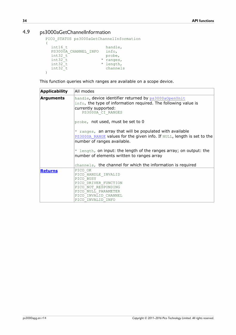
4.9 ps3000aGetChannelInformationPICO_STATUS ps3000aGetChannelInformation(
int16_t handle,PS3000A_CHANNEL_INFO info,int32_t probe,int32_t * ranges,int32_t * length,int32_t channels
)
This function queries which ranges are available on a scope device.
Applicability All modes
Arguments handle, device identifier returned by ps3000aOpenUnit
info, the type of information required. The following value is
currently supported:PS3000A_CI_RANGES
probe, not used, must be set to 0
* ranges, an array that will be populated with available
PS3000A_RANGE values for the given info. If NULL, length is set to the
number of ranges available.
* length, on input: the length of the ranges array; on output: the
number of elements written to ranges array
channels, the channel for which the information is required
Returns PICO_OK PICO_HANDLE_INVALIDPICO_BUSYPICO_DRIVER_FUNCTIONPICO_NOT_RESPONDINGPICO_NULL_PARAMETERPICO_INVALID_CHANNELPICO_INVALID_INFO
PicoScope 3000 Series (A API) Programmer's Guide 35
Copyright © 2011–2016 Pico Technology Limited. All rights reserved. ps3000apg.en r14
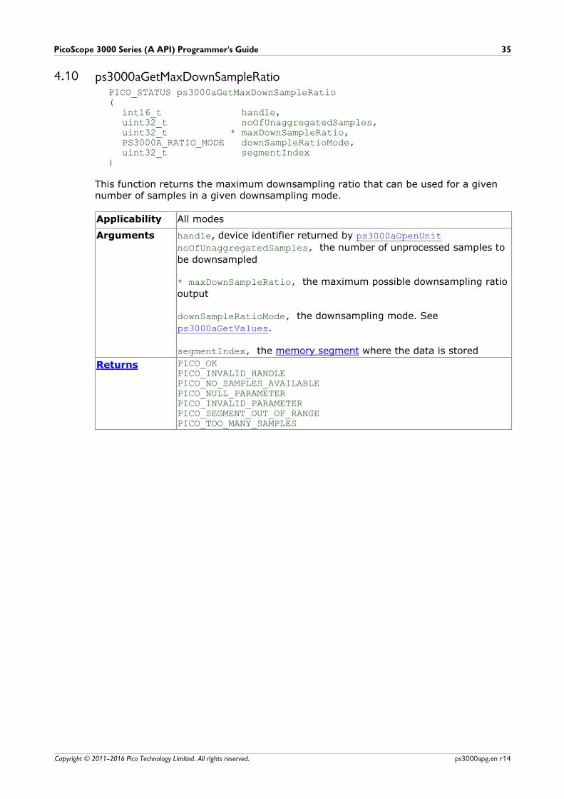
4.10 ps3000aGetMaxDownSampleRatioPICO_STATUS ps3000aGetMaxDownSampleRatio(
int16_t handle,uint32_t noOfUnaggregatedSamples,uint32_t * maxDownSampleRatio, PS3000A_RATIO_MODE downSampleRatioMode,uint32_t segmentIndex
)
This function returns the maximum downsampling ratio that can be used for a givennumber of samples in a given downsampling mode.
Applicability All modes
Arguments handle, device identifier returned by ps3000aOpenUnit
noOfUnaggregatedSamples, the number of unprocessed samples to
be downsampled
* maxDownSampleRatio, the maximum possible downsampling ratio
output
downSampleRatioMode, the downsampling mode. See
ps3000aGetValues.
segmentIndex, the memory segment where the data is stored
Returns PICO_OKPICO_INVALID_HANDLEPICO_NO_SAMPLES_AVAILABLEPICO_NULL_PARAMETERPICO_INVALID_PARAMETERPICO_SEGMENT_OUT_OF_RANGEPICO_TOO_MANY_SAMPLES
API functions36
Copyright © 2011–2016 Pico Technology Limited. All rights reserved.ps3000apg.en r14
4.11 ps3000aGetMaxEtsValuesPICO_STATUS ps3000aGetMaxEtsValues(
int16_t handle,int16_t * etsCycles,int16_t * etsInterleave
)
This function returns the maximum number of cycles and maximum interleaving factorthat can be used for the selected scope device in ETS mode. These values are theupper limits for the etsCycles and etsInterleave arguments supplied to
ps3000SetEts.
Applicability All modes
Arguments handle, device identifier returned by ps3000aOpenUnit
etsCycles, the maximum value of the etsCycles argument
supplied to ps3000SetEts
etsInterleave, the maximum value of the etsInterleave
argument supplied to ps3000SetEts
Returns PICO_OKPICO_INVALID_HANDLEPICO_DRIVER_FUNCTION
PICO_NULL_PARAMETER - if etsCycles and etsInterleave are bothNULL
PicoScope 3000 Series (A API) Programmer's Guide 37
Copyright © 2011–2016 Pico Technology Limited. All rights reserved. ps3000apg.en r14
4.12 ps3000aGetMaxSegmentsPICO_STATUS ps3000aGetMaxSegments(
int16_t handle,uint32_t * maxsegments
)
This function returns the maximum number of segments allowed for the openeddevice. This number is the maximum value of nsegments that can be passed to
ps3000aMemorySegments.
Applicability All modes
Arguments handle, device identifier returned by ps3000aOpenUnit
* maxsegments, on exit, the maximum number of segments allowed
Returns PICO_OK PICO_INVALID_HANDLEPICO_DRIVER_FUNCTIONPICO_NULL_PARAMETER
API functions38
Copyright © 2011–2016 Pico Technology Limited. All rights reserved.ps3000apg.en r14
4.13 ps3000aGetNoOfCapturesPICO_STATUS ps3000aGetNoOfCaptures(
int16_t handle, uint32_t * nCaptures
)
This function returns the number of waveforms that the device has captured. It can becalled during waveform capture.
It can be called in rapid block mode after ps3000aRunBlock has been called and either
the collection completed or the collection of waveforms was interrupted by calling ps3000aStop. The returned value (nCaptures) can then be used to iterate through the
number of segments using ps3000aGetValues, or in a single call to
ps3000aGetValuesBulk where it is used to calculate the toSegmentIndex parameter.
Applicability Rapid block mode
Arguments handle, device identifier returned by ps3000aOpenUnit
* nCaptures, output: the number of available captures that has
been collected from calling ps3000aRunBlock
Returns PICO_OKPICO_DRIVER_FUNCTIONPICO_INVALID_HANDLEPICO_NOT_RESPONDINGPICO_NO_SAMPLES_AVAILABLEPICO_NULL_PARAMETERPICO_INVALID_PARAMETERPICO_SEGMENT_OUT_OF_RANGEPICO_TOO_MANY_SAMPLES
PicoScope 3000 Series (A API) Programmer's Guide 39
Copyright © 2011–2016 Pico Technology Limited. All rights reserved. ps3000apg.en r14
4.14 ps3000aGetNoOfProcessedCapturesPICO_STATUS ps3000aGetNoOfProcessedCaptures (
int16_t handle,uint32_t * nProcessedCaptures
)
This function gets the number of captures collected and processed in one run of rapidblock mode. It enables your application to start processing captured data while thedriver is still transferring later captures from the device to the computer.
The function returns the number of captures the driver has processed since you called ps3000aRunBlock. It is for use in rapid block mode, alongside the
ps3000aGetValuesOverlappedBulk function, when the driver is set to transfer data
from the device automatically as soon as the ps3000aRunBlock function is called. You
can call ps3000aGetNoOfProcessedCaptures during device capture, after collection
has completed or after interrupting waveform collection by calling ps3000aStop.
The returned value (nProcessedCaptures) can then be used to iterate through the
number of segments using ps3000aGetValues, or in a single call to
ps3000aGetValuesBulk, where it is used to calculate the toSegmentIndex parameter.
When capture is stopped
If nProcessedCaptures = 0, you will also need to call ps3000aGetNoOfCaptures, in
order to determine how many waveform segments were captured, before calling ps3000aGetValues or ps3000aGetValuesBulk.
Applicability Rapid block mode
Arguments handle, the handle of the device.
* nProcessedCaptures, on exit, the number of waveforms captured
and processed.
Returns PICO_OKPICO_INVALID_HANDLEPICO_INVALID_PARAMETER

API functions40
Copyright © 2011–2016 Pico Technology Limited. All rights reserved.ps3000apg.en r14
4.15 ps3000aGetStreamingLatestValuesPICO_STATUS ps3000aGetStreamingLatestValues (
int16_t handle,ps3000aStreamingReady lpPs3000AReady,void * pParameter
)
This function instructs the driver to return the next block of values to your ps3000aStreamingReady callback. You must have previously called
ps3000aRunStreaming beforehand to set up streaming.
Applicability Streaming mode only
Arguments handle, device identifier returned by ps3000aOpenUnit
lpPs3000AReady, a pointer to your ps3000aStreamingReady
callback
* pParameter, a void pointer that will be passed to the
ps3000aStreamingReady callback. The callback may optionally use
this pointer to return information to the application.
Returns PICO_OKPICO_POWER_SUPPLY_CONNECTEDPICO_POWER_SUPPLY_NOT_CONNECTED PICO_INVALID_HANDLEPICO_NO_SAMPLES_AVAILABLEPICO_INVALID_CALLPICO_BUSYPICO_NOT_RESPONDINGPICO_DRIVER_FUNCTION
PicoScope 3000 Series (A API) Programmer's Guide 41
Copyright © 2011–2016 Pico Technology Limited. All rights reserved. ps3000apg.en r14
4.16 ps3000aGetTimebasePICO_STATUS ps3000aGetTimebase (
int16_t handle,uint32_t timebase,int32_t noSamples,int32_t * timeIntervalNanoseconds,int16_t oversample,int32_t * maxSamples,uint32_t segmentIndex
)
This function calculates the sampling rate and maximum number of samples for agiven timebase under the specified conditions. The result will depend on the number ofchannels enabled by the last call to ps3000aSetChannel.
This function is provided for use with programming languages that do not support the float data type. The value returned in the timeIntervalNanoseconds argument is
restricted to integers. If your programming language supports the float type, we
recommend that you use ps3000aGetTimebase2 instead.
To use ps3000aGetTimebase or ps3000aGetTimebase2, first estimate the timebase
number that you require using the information in the timebase guide. Next, call one ofthese functions with the timebase that you have just chosen and verify that the timeIntervalNanoseconds argument that the function returns is the value that you
require. You may need to iterate this process until you obtain the time interval thatyou need.
Applicability All modes
Arguments handle, device identifier returned by ps3000aOpenUnit
timebase, see timebase guide. This value can be supplied to
ps3000aRunBlock to define the sampling interval.
noSamples, the number of samples required
* timeIntervalNanoseconds, on exit, the time interval between
readings at the selected timebase. Use NULL if not required.
oversample, not used
* maxSamples, on exit, the maximum number of samples available.
The scope allocates a certain amount of memory for internaloverheads and this may vary depending on the number of segments,number of channels enabled, and the timebase chosen. Use NULL if
not required.
segmentIndex, the index of the memory segment to use
Returns PICO_OKPICO_INVALID_HANDLEPICO_TOO_MANY_SAMPLESPICO_INVALID_CHANNELPICO_INVALID_TIMEBASEPICO_INVALID_PARAMETERPICO_SEGMENT_OUT_OF_RANGEPICO_DRIVER_FUNCTION
API functions42
Copyright © 2011–2016 Pico Technology Limited. All rights reserved.ps3000apg.en r14
4.17 ps3000aGetTimebase2PICO_STATUS ps3000aGetTimebase2 (
int16_t handle,uint32_t timebase,int32_t noSamples,float * timeIntervalNanoseconds,int16_t oversample,int32_t * maxSamples,uint32_t segmentIndex
)
This function is an upgraded version of ps3000aGetTimebase, and returns the time
interval as a float rather than an int32_t. This allows it to return sub-nanosecond
time intervals. See ps3000aGetTimebase for a full description.
Applicability All modes
Arguments * timeIntervalNanoseconds, a pointer to the time interval between
readings at the selected timebase. If a null pointer is passed, nothingwill be written here.
All other arguments: see ps3000aGetTimebase.
Returns See ps3000aGetTimebase.
PicoScope 3000 Series (A API) Programmer's Guide 43
Copyright © 2011–2016 Pico Technology Limited. All rights reserved. ps3000apg.en r14
4.18 ps3000aGetTriggerInfoBulkPICO_STATUS ps3000aGetTriggerInfoBulk(
int16_t handle,PS3000A_TRIGGER_INFO * triggerInfo,uint32_t fromSegmentIndex,uint32_t toSegmentIndex
)
This function returns trigger information in rapid block mode.
Applicability Rapid block mode.PicoScope 3207A and 3207B only.
Arguments handle, device identifier returned by ps3000aOpenUnit
triggerInfo, an array of pointers to PS3000A_TRIGGER_INFO
structures that, on exit, will contain information on each triggerevent. There will be one structure for each segment in the range [fromSegmentIndex, toSegmentIndex].
fromSegmentIndex, the number of the first memory segment for
which information is required
toSegmentIndex, the number of the last memory segment for which
information is required
Returns PICO_NOT_SUPPORTED_BY_THIS_DEVICEPICO_NO_SAMPLES_AVAILABLEPICO_NULL_PARAMETERPICO_SEGMENT_OUT_OF_RANGEPICO_NOT_USED_IN_THIS_CAPTURE_MODEPICO_ETS_MODE_SETPICO_OKPICO_NOT_RESPONDINGPICO_INVALID_HANDLEPICO_DRIVER_FUNCTION
API functions44
Copyright © 2011–2016 Pico Technology Limited. All rights reserved.ps3000apg.en r14
4.19 ps3000aGetTriggerTimeOffsetPICO_STATUS ps3000aGetTriggerTimeOffset(
int16_t handle,uint32_t * timeUpper,uint32_t * timeLower,PS3000A_TIME_UNITS * timeUnits,uint32_t segmentIndex
)
This function gets the trigger time offset for waveforms obtained in block mode orrapid block mode. The trigger time offset is an adjustment value used for correctingjitter in the waveform, and is intended mainly for applications that wish to display thewaveform with reduced jitter. The offset is zero if the waveform crosses the thresholdat the trigger sampling instant, or a positive or negative value if jitter correction isrequired. The value should be added to the nominal trigger time to get the correctedtrigger time.
Call this function after data has been captured or when data has been retrieved from aprevious capture.
This function is provided for use in programming environments that do not support 64-bit integers. Another version of this function, ps3000aGetTriggerTimeOffset64, is
available that returns the time as a single 64-bit value.
Applicability Block mode, rapid block mode
Arguments handle, device identifier returned by ps3000aOpenUnit
* timeUpper, on exit, the upper 32 bits of the trigger time offset
* timeLower, on exit, the lower 32 bits of the trigger time offset
* timeUnits, returns the time units in which timeUpper:timeLower
is measured. The allowable values are:PS3000A_FSPS3000A_PSPS3000A_NSPS3000A_USPS3000A_MSPS3000A_S
segmentIndex, the number of the memory segment for which the
information is required
Returns PICO_OKPICO_INVALID_HANDLEPICO_DEVICE_SAMPLINGPICO_SEGMENT_OUT_OF_RANGEPICO_NOT_USED_IN_THIS_CAPTURE_MODEPICO_NOT_RESPONDINGPICO_NULL_PARAMETERPICO_NO_SAMPLES_AVAILABLEPICO_DRIVER_FUNCTION
PicoScope 3000 Series (A API) Programmer's Guide 45
Copyright © 2011–2016 Pico Technology Limited. All rights reserved. ps3000apg.en r14
4.20 ps3000aGetTriggerTimeOffset64PICO_STATUS ps3000aGetTriggerTimeOffset64(
int16_t handle,int64_t * time,PS3000A_TIME_UNITS * timeUnits,uint32_t segmentIndex
)
This function gets the trigger time offset for a waveform. It is equivalent to ps3000aGetTriggerTimeOffset except that the time offset is returned as a single 64-
bit value instead of two 32-bit values.
Applicability Block mode, rapid block mode
Arguments handle, device identifier returned by ps3000aOpenUnit
* time, on exit, the time at which the trigger point occurred
* timeUnits,
segmentIndex, see ps3000aGetTriggerTimeOffset
Returns PICO_OKPICO_INVALID_HANDLEPICO_DEVICE_SAMPLINGPICO_SEGMENT_OUT_OF_RANGEPICO_NOT_USED_IN_THIS_CAPTURE_MODEPICO_NOT_RESPONDINGPICO_NULL_PARAMETERPICO_NO_SAMPLES_AVAILABLEPICO_DRIVER_FUNCTION

API functions46
Copyright © 2011–2016 Pico Technology Limited. All rights reserved.ps3000apg.en r14
4.21 ps3000aGetUnitInfoPICO_STATUS ps3000aGetUnitInfo (
int16_t handle, int8_t * string,int16_t stringLength,int16_t * requiredSize,PICO_INFO info
)
This function retrieves information about the specified oscilloscope. If the device failsto open or no device is opened, only the driver version is available.
Applicability All modes
Arguments handle, the identifier of the device to query. If an invalid handle is
passed, only the driver versions can be read.
* string, on exit, the information string selected specified by the
info argument. If string is NULL, only requiredSize is returned.
stringLength, on entry, the maximum number of int8_t that may
be written to string
* requiredSize, on exit, the required length of the string array
info, a number specifying what information is required. The
possible values are listed in the table below.
Returns PICO_OKPICO_INVALID_HANDLEPICO_NULL_PARAMETERPICO_INVALID_INFOPICO_INFO_UNAVAILABLEPICO_DRIVER_FUNCTION
info Example
0 PICO_DRIVER_VERSION
Version number of PicoScope ps3000a DLL
1.0.0.1
1 PICO_USB_VERSION
Type of USB connection to device: 1.1, 2.0 or 3.0
2.0
2 PICO_HARDWARE_VERSION
Hardware version of device
1
3 PICO_VARIANT_INFO
Variant number of device
3206B
4 PICO_BATCH_AND_SERIAL
Batch and serial number of device
KJL87/006
5 PICO_CAL_DATE
Calibration date of device
30Sep09
6 PICO_KERNEL_VERSION
Version of kernel driver
1.0
7 PICO_DIGITAL_HARDWARE_VERSION
Hardware version of the digital section
1
8 PICO_ANALOGUE_HARDWARE_VERSION
Hardware version of the analog section
1
9 PICO_FIRMWARE_VERSION_1 1.0.0.0
10 PICO_FIRMWARE_VERSION_2 1.0.0.0
PicoScope 3000 Series (A API) Programmer's Guide 47
Copyright © 2011–2016 Pico Technology Limited. All rights reserved. ps3000apg.en r14
4.22 ps3000aGetValuesPICO_STATUS ps3000aGetValues(
int16_t handle,uint32_t startIndex,uint32_t * noOfSamples,uint32_t downSampleRatio,PS3000A_RATIO_MODE downSampleRatioMode,uint32_t segmentIndex,int16_t * overflow
)
This function returns block-mode data, with or without downsampling, starting at thespecified sample number. It is used to get the stored data from the scope after datacollection has stopped.
Applicability Block mode, rapid block mode
Arguments handle, device identifier returned by ps3000aOpenUnit
startIndex, a zero-based index that indicates the start point for
data collection. It is measured in sample intervals from the start ofthe buffer.
* noOfSamples, on entry, the number of samples required. On exit,
the actual number retrieved. The number of samples retrieved willnot be more than the number requested, and the data retrievedstarts at startIndex.
downSampleRatio, the downsampling factor that will be applied to
the raw data
downSampleRatioMode, which downsampling mode to use. The
available values are: -PS3000A_RATIO_MODE_NONE (downSampleRatio is ignored)PS3000A_RATIO_MODE_AGGREGATEPS3000A_RATIO_MODE_AVERAGEPS3000A_RATIO_MODE_DECIMATE
AGGREGATE, AVERAGE, DECIMATE are single-bit constants that can be
ORed to apply multiple downsampling modes to the same data
segmentIndex, the zero-based number of the memory segment
where the data is stored
* overflow, on exit, a set of flags that indicate whether an
overvoltage has occurred on any of the channels. It is a bit field withbit 0 denoting Channel A.
API functions48
Copyright © 2011–2016 Pico Technology Limited. All rights reserved.ps3000apg.en r14
Returns PICO_OKPICO_INVALID_HANDLEPICO_POWER_SUPPLY_CONNECTEDPICO_POWER_SUPPLY_NOT_CONNECTED PICO_NO_SAMPLES_AVAILABLEPICO_DEVICE_SAMPLINGPICO_NULL_PARAMETERPICO_SEGMENT_OUT_OF_RANGEPICO_STARTINDEX_INVALIDPICO_ETS_NOT_RUNNINGPICO_BUFFERS_NOT_SETPICO_INVALID_PARAMETERPICO_TOO_MANY_SAMPLESPICO_DATA_NOT_AVAILABLEPICO_STARTINDEX_INVALIDPICO_INVALID_SAMPLERATIOPICO_INVALID_CALLPICO_NOT_RESPONDINGPICO_MEMORYPICO_RATIO_MODE_NOT_SUPPORTEDPICO_DRIVER_FUNCTION
4.22.1 Downsampling modes
Various methods of data reduction, or downsampling, are possible with PicoScopeoscilloscopes. The downsampling is done at high speed by dedicated hardware insidethe scope, making your application faster and more responsive than if you had to doall the data processing in software.
You specify the downsampling mode when you call one of the data collection functionssuch as ps3000aGetValues. The following modes are available:
PS3000A_RATIO_MODE_NONE No downsampling. Returns the raw datavalues.
PS3000A_RATIO_MODE_AGGREGATE Reduces every block of n values to just twovalues: a minimum and a maximum. Theminimum and maximum values arereturned in two separate buffers.
PS3000A_RATIO_MODE_DECIMATE Reduces every block of n values to just thefirst value in the block, discarding all theother values.
PS3000A_RATIO_MODE_AVERAGE Reduces every block of n values to a singlevalue representing the average (arithmeticmean) of all the values.
PicoScope 3000 Series (A API) Programmer's Guide 49
Copyright © 2011–2016 Pico Technology Limited. All rights reserved. ps3000apg.en r14
4.23 ps3000aGetValuesAsyncPICO_STATUS ps3000aGetValuesAsync(
int16_t handle,uint32_t startIndex,uint32_t noOfSamples,uint32_t downSampleRatio,PS3000A_RATIO_MODE downSampleRatioMode,uint32_t segmentIndex,void * lpDataReady, void * pParameter
)
This function returns data either with or without downsampling, starting at thespecified sample number. It is used to get the stored data from the device (in blockmode) or the driver (in streaming mode) after data collection has stopped. It returnsthe data using a callback.
Applicability Streaming mode and block mode
Arguments handle, device identifier returned by ps3000aOpenUnitstartIndex,noOfSamples,downSampleRatio,downSampleRatioMode,
segmentIndex: see ps3000aGetValues
* lpDataReady, a pointer to the user-supplied function that will be
called when the data is ready. This will be ps3000aDataReady for
block-mode data or ps3000aStreamingReady for streaming-mode
data.
* pParameter, a void pointer that will be passed to the callback
function. The data type is determined by the application.
Returns PICO_OKPICO_POWER_SUPPLY_CONNECTEDPICO_POWER_SUPPLY_NOT_CONNECTED PICO_INVALID_HANDLEPICO_NO_SAMPLES_AVAILABLEPICO_DEVICE_SAMPLINGPICO_NULL_PARAMETERPICO_STARTINDEX_INVALIDPICO_SEGMENT_OUT_OF_RANGEPICO_INVALID_PARAMETERPICO_DATA_NOT_AVAILABLEPICO_INVALID_SAMPLERATIOPICO_INVALID_CALLPICO_DRIVER_FUNCTION
API functions50
Copyright © 2011–2016 Pico Technology Limited. All rights reserved.ps3000apg.en r14
4.24 ps3000aGetValuesBulkPICO_STATUS ps3000aGetValuesBulk(
int16_t handle,uint32_t * noOfSamples,uint32_t fromSegmentIndex,uint32_t toSegmentIndex,uint32_t downSampleRatio,PS3000A_RATIO_MODE downSampleRatioMode,int16_t * overflow
)
This function retrieves waveforms captured using rapid block mode. The waveformsmust have been collected sequentially and in the same run.
Applicability Rapid block mode
Arguments handle, device identifier returned by ps3000aOpenUnit
* noOfSamples, on entry, the number of samples required; on exit,
the actual number retrieved. The number of samples retrieved willnot be more than the number requested. The data retrieved alwaysstarts with the first sample captured.
fromSegmentIndex, the first segment from which the waveform
should be retrieved
toSegmentIndex, the last segment from which the waveform should
be retrieved
downSampleRatio,
downSampleRatioMode, see ps3000aGetValues
* overflow, an array of integers equal to or larger than the number
of waveforms to be retrieved. Each segment index has acorresponding entry in the overflow array, with overflow[0]
containing the flags for the segment numbered fromSegmentIndex
and the last element in the array containing the flags for the segmentnumbered toSegmentIndex. Each element in the array is a bit field as
described under ps3000aGetValues.
Returns PICO_OKPICO_POWER_SUPPLY_CONNECTEDPICO_POWER_SUPPLY_NOT_CONNECTED PICO_INVALID_HANDLEPICO_INVALID_PARAMETERPICO_INVALID_SAMPLERATIOPICO_ETS_NOT_RUNNINGPICO_BUFFERS_NOT_SETPICO_TOO_MANY_SAMPLESPICO_SEGMENT_OUT_OF_RANGEPICO_NO_SAMPLES_AVAILABLEPICO_NOT_RESPONDINGPICO_DRIVER_FUNCTION
PicoScope 3000 Series (A API) Programmer's Guide 51
Copyright © 2011–2016 Pico Technology Limited. All rights reserved. ps3000apg.en r14
4.25 ps3000aGetValuesOverlappedPICO_STATUS ps3000aGetValuesOverlapped(
int16_t handle,uint32_t startIndex,uint32_t * noOfSamples,uint32_t downSampleRatio,PS3000A_RATIO_MODE downSampleRatioMode,uint32_t segmentIndex,int16_t * overflow
)
This function allows you to make a deferred data-collection request in block mode. Therequest will be executed, and the arguments validated, when you call ps3000aRunBlock. The advantage of this function is that the driver makes contact with
the scope only once, when you call ps3000aRunBlock, compared with the two contacts
that occur when you use the conventional ps3000aRunBlock, ps3000aGetValues
calling sequence. This slightly reduces the dead time between successive captures inblock mode.
After calling ps3000aRunBlock, you can optionally use ps3000aGetValues to request
further copies of the data. This might be required if you wish to display the data withdifferent data reduction settings.
See also: Using the GetValuesOverlapped functions.
Applicability Block mode
Arguments handle, device identifier returned by ps3000aOpenUnitstartIndex,* noOfSamples,downSampleRatio,downSampleRatioMode,
segmentIndex: see ps3000aGetValues
* overflow, see ps3000aGetValuesBulk
Returns PICO_OKPICO_POWER_SUPPLY_CONNECTEDPICO_POWER_SUPPLY_NOT_CONNECTED PICO_INVALID_HANDLEPICO_INVALID_PARAMETERPICO_DRIVER_FUNCTION

API functions52
Copyright © 2011–2016 Pico Technology Limited. All rights reserved.ps3000apg.en r14
4.26 ps3000aGetValuesOverlappedBulkPICO_STATUS ps3000aGetValuesOverlappedBulk(
int16_t handle,uint32_t startIndex,uint32_t * noOfSamples,uint32_t downSampleRatio,PS3000A_RATIO_MODE downSampleRatioMode,uint32_t fromSegmentIndex,uint32_t toSegmentIndex,int16_t * overflow
)
This function requests data from multiple segments in rapid block mode. It is similar tocalling ps3000aGetValuesOverlapped multiple times, but more efficient.
See also: Using the GetValuesOverlapped functions.
Applicability Rapid block mode
Arguments handle, device identifier returned by ps3000aOpenUnitstartIndex,* noOfSamples,downSampleRatio,
downSampleRatioMode: see ps3000aGetValues
fromSegmentIndex,toSegmentIndex,
* overflow: see ps3000aGetValuesBulk
Returns PICO_OKPICO_POWER_SUPPLY_CONNECTEDPICO_POWER_SUPPLY_NOT_CONNECTED PICO_INVALID_HANDLEPICO_INVALID_PARAMETERPICO_DRIVER_FUNCTION

PicoScope 3000 Series (A API) Programmer's Guide 53
Copyright © 2011–2016 Pico Technology Limited. All rights reserved. ps3000apg.en r14
4.26.1 Using the GetValuesOverlapped functions
1. Open the oscilloscope using ps3000aOpenUnit.
2. Select channel ranges and AC/DC coupling using ps3000aSetChannel.
3. Using ps3000aGetTimebase, select timebases until the required sampling interval
is located.
4. Use the trigger setup functions ps3000aSetTriggerChannelDirections and
ps3000aSetTriggerChannelProperties to set up the trigger if required.
5. Use ps3000aSetDataBuffer to tell the driver where your memory buffer is.
6. Set up the transfer of the block of data from the oscilloscope usingps3000aGetValuesOverlapped.
7. Start the oscilloscope running using ps3000aRunBlock.
8. Wait until the oscilloscope is ready using the ps3000aBlockReady callback (or poll
using ps3000aIsReady).
9. Display the data.
10. Repeat steps 7 to 9 if needed.
11. Stop the oscilloscope using ps3000aStop.
A similar procedure can be used with rapid block mode using theps3000aGetValuesOverlappedBulk function.
API functions54
Copyright © 2011–2016 Pico Technology Limited. All rights reserved.ps3000apg.en r14
4.27 ps3000aGetValuesTriggerTimeOffsetBulkPICO_STATUS ps3000aGetValuesTriggerTimeOffsetBulk(
int16_t handle,uint32_t * timesUpper,uint32_t * timesLower,PS3000A_TIME_UNITS * timeUnits,uint32_t fromSegmentIndex,uint32_t toSegmentIndex
)
This function retrieves the trigger time offset for multiple waveforms obtained in blockmode or rapid block mode. It is a more efficient alternative to callingps3000aGetTriggerTimeOffset once for each waveform required. See
ps3000aGetTriggerTimeOffset for an explanation of trigger time offsets.
There is another version of this function, ps3000aGetValuesTriggerTimeOffsetBulk64, that returns trigger time offsets as 64-
bit values instead of pairs of 32-bit values.
Applicability Block mode, rapid block mode
Arguments
handle, device identifier returned by ps3000aOpenUnit
* timesUpper, * timesLower, two arrays of integers. On exit, they hold the most
significant 32 bits and least significant 32 bits of the trigger time offset for eachrequested segment index. timesUpper[0] and timesLower[0] hold the
fromSegmentIndex time offset and the last timesUpper and timesLower elements
hold the toSegmentIndex time offset. The arrays must be long enough to hold the
number of requested times.
* timeUnits, an array of integers. On exit, timeUnits[0] contains the time unit for
fromSegmentIndex and the last element contains the time unit for toSegmentIndex.
Refer to ps3000aGetTriggerTimeOffset for allowable values. The array must be long
enough to hold the number of requested times.
fromSegmentIndex, the first segment for which the time offset is required
toSegmentIndex, the last segment for which the time offset is required. If
toSegmentIndex is less than fromSegmentIndex, the driver will wrap around from the
last segment to the first.
Returns PICO_OKPICO_POWER_SUPPLY_CONNECTEDPICO_POWER_SUPPLY_NOT_CONNECTED PICO_INVALID_HANDLEPICO_NOT_USED_IN_THIS_CAPTURE_MODEPICO_NOT_RESPONDINGPICO_NULL_PARAMETERPICO_DEVICE_SAMPLINGPICO_SEGMENT_OUT_OF_RANGEPICO_NO_SAMPLES_AVAILABLEPICO_DRIVER_FUNCTION

PicoScope 3000 Series (A API) Programmer's Guide 55
Copyright © 2011–2016 Pico Technology Limited. All rights reserved. ps3000apg.en r14
4.28 ps3000aGetValuesTriggerTimeOffsetBulk64PICO_STATUS ps3000aGetValuesTriggerTimeOffsetBulk64(
int16_t handle,int64_t * times,PS3000A_TIME_UNITS * timeUnits,uint32_t fromSegmentIndex,uint32_t toSegmentIndex
)
This function is equivalent to ps3000aGetValuesTriggerTimeOffsetBulk but retrieves
the trigger time offsets as 64-bit values instead of pairs of 32-bit values.
Applicability Block mode, rapid block mode
Arguments handle, device identifier returned by ps3000aOpenUnit
* times, an array of integers. On exit, this holds the trigger time
offset for each requested segment index. Each value is equivalent tothe timesUpper:timesLower value returned by
ps3000aGetValuesTriggerTimeOffsetBulk. See the description of
that function for more information.
* timeUnits,
fromSegmentIndex,
toSegmentIndex, see ps3000aGetValuesTriggerTimeOffsetBulk
Returns PICO_OKPICO_POWER_SUPPLY_CONNECTEDPICO_POWER_SUPPLY_NOT_CONNECTED PICO_INVALID_HANDLEPICO_NOT_USED_IN_THIS_CAPTURE_MODEPICO_NOT_RESPONDINGPICO_NULL_PARAMETERPICO_DEVICE_SAMPLINGPICO_SEGMENT_OUT_OF_RANGEPICO_NO_SAMPLES_AVAILABLEPICO_DRIVER_FUNCTION
API functions56
Copyright © 2011–2016 Pico Technology Limited. All rights reserved.ps3000apg.en r14
4.29 ps3000aHoldOffPICO_STATUS ps3000aHoldOff(
int16_t handle,uint64_t holdoff,PS3000A_HOLDOFF_TYPE type
)
This function is for backward compatibility only and does nothing.
Applicability None
Arguments handle, device identifier returned by ps3000aOpenUnit
holdoff, not used
type, not used
Returns Undefined

PicoScope 3000 Series (A API) Programmer's Guide 57
Copyright © 2011–2016 Pico Technology Limited. All rights reserved. ps3000apg.en r14
4.30 ps3000aIsReadyPICO_STATUS ps3000aIsReady(
int16_t handle,int16_t * ready
)
This function may be used instead of a callback function to receive data from ps3000aRunBlock. To use this method, pass a NULL pointer as the lpReady argument
to ps3000aRunBlock. You must then poll the driver to see if it has finished collecting
the requested samples.
Applicability Block mode
Arguments handle, device identifier returned by ps3000aOpenUnit
* ready, output: indicates the state of the collection. If zero, the
device is still collecting. If non-zero, the device has finishedcollecting and ps3000aGetValues can be used to retrieve the data.
Returns PICO_OKPICO_INVALID_HANDLEPICO_DRIVER_FUNCTIONPICO_NULL_PARAMETERPICO_NO_SAMPLES_AVAILABLEPICO_CANCELLEDPICO_NOT_RESPONDING

API functions58
Copyright © 2011–2016 Pico Technology Limited. All rights reserved.ps3000apg.en r14
4.31 ps3000aIsTriggerOrPulseWidthQualifierEnabledPICO_STATUS ps3000aIsTriggerOrPulseWidthQualifierEnabled(
int16_t handle,int16_t * triggerEnabled,int16_t * pulseWidthQualifierEnabled
)
This function discovers whether a trigger, or pulse width triggering, is enabled.
Applicability Call after setting up the trigger, and just before calling either ps3000aRunBlock or ps3000aRunStreaming.
Arguments handle, device identifier returned by ps3000aOpenUnit
* triggerEnabled, on exit, indicates whether the trigger will
successfully be set when ps3000aRunBlock or ps3000aRunStreaming
is called. A non-zero value indicates that the trigger is set, zero thatthe trigger is not set.
* pulseWidthQualifierEnabled, on exit, indicates whether the
pulse width qualifier will successfully be set when ps3000aRunBlock
or ps3000aRunStreaming is called. A non-zero value indicates that
the pulse width qualifier is set, zero that the pulse width qualifier isnot set.
Returns PICO_OKPICO_INVALID_HANDLEPICO_NULL_PARAMETERPICO_DRIVER_FUNCTION
PicoScope 3000 Series (A API) Programmer's Guide 59
Copyright © 2011–2016 Pico Technology Limited. All rights reserved. ps3000apg.en r14
4.32 ps3000aMaximumValuePICO_STATUS ps3000aMaximumValue(
int16_t handle,int16_t * value
)
This function returns the maximum ADC count returned by calls to get values.
Applicability All modes
Arguments handle, device identifier returned by ps3000aOpenUnit
* value, returns the maximum ADC value
Returns PICO_OKPICO_USER_CALLBACKPICO_INVALID_HANDLEPICO_TOO_MANY_SEGMENTSPICO_MEMORYPICO_DRIVER_FUNCTION
API functions60
Copyright © 2011–2016 Pico Technology Limited. All rights reserved.ps3000apg.en r14
4.33 ps3000aMemorySegmentsPICO_STATUS ps3000aMemorySegments( int16_t handle, uint32_t nSegments, int32_t * nMaxSamples)
This function sets the number of memory segments that the scope will use.
When the scope is opened, the number of segments defaults to 1, meaning that eachcapture fills the scope's available memory. This function allows you to divide thememory into a number of segments so that the scope can store several waveformssequentially.
Applicability All modes
Arguments handle, device identifier returned by ps3000aOpenUnit
nSegments, the number of segments required, from 1 to the value
of maxsegments returned by ps3000aGetMaxSegments
* nMaxSamples, on exit, the number of samples available in each
segment. This is the total number over all channels, so if more thanone channel is in use, the number of samples available to eachchannel is nMaxSamples divided by 2 (for 2 channels) or 4 (for 3 or 4
channels).
Returns PICO_OKPICO_USER_CALLBACKPICO_INVALID_HANDLEPICO_TOO_MANY_SEGMENTSPICO_MEMORYPICO_DRIVER_FUNCTION
PicoScope 3000 Series (A API) Programmer's Guide 61
Copyright © 2011–2016 Pico Technology Limited. All rights reserved. ps3000apg.en r14
4.34 ps3000aMinimumValuePICO_STATUS ps3000aMinimumValue(
int16_t handle,int16_t * value
)
This function returns the minimum ADC count returned by calls to ps3000aGetValues
and related functions
Applicability All modes
Arguments handle, device identifier returned by ps3000aOpenUnit
* value, returns the minimum ADC value
Returns PICO_OKPICO_USER_CALLBACKPICO_INVALID_HANDLEPICO_TOO_MANY_SEGMENTSPICO_MEMORYPICO_DRIVER_FUNCTION
API functions62
Copyright © 2011–2016 Pico Technology Limited. All rights reserved.ps3000apg.en r14
4.35 ps3000aNoOfStreamingValuesPICO_STATUS ps3000aNoOfStreamingValues (
int16_t handle,uint32_t * noOfValues
)
This function returns the number of samples available after data collection in streaming mode. Call it after calling ps3000aStop. The maximum number possible is
the sum of the maxPreTriggerSamples + maxPostTriggerSamples arguments passed
to ps3000aRunStreaming.
Applicability Streaming mode
Arguments handle, device identifier returned by ps3000aOpenUnit
* noOfValues, on exit, the number of samples
Returns PICO_OKPICO_INVALID_HANDLEPICO_NULL_PARAMETERPICO_NO_SAMPLES_AVAILABLEPICO_NOT_USEDPICO_BUSYPICO_DRIVER_FUNCTION

PicoScope 3000 Series (A API) Programmer's Guide 63
Copyright © 2011–2016 Pico Technology Limited. All rights reserved. ps3000apg.en r14
4.36 ps3000aOpenUnitPICO_STATUS ps3000aOpenUnit(
int16_t * handle,int8_t * serial
)
This function opens a PicoScope 3000 Series oscilloscope attached to the computer.The maximum number of units that can be opened depends on the operating system,the kernel driver and the computer.
If the function returns PICO_POWER_SUPPLY_NOT_CONNECTED, call
ps3000aChangePowerSource to switch from the external power supply to USB power.
If the return value is PICO_USB3_0_DEVICE_NON_USB3_0_PORT, call
ps3000aChangePowerSource to tell the driver to power the device from a USB 2.0 or
USB 1.1 port.
Applicability All modes
Arguments * handle, on exit, the result of the attempt to open a scope:
–1 : if the scope fails to open0 : if no scope is found> 0 : a number that uniquely identifies the scope
If a valid handle is returned, it must be used in all subsequent callsto API functions to identify this scope.
* serial, on entry, a null-terminated string containing the serial
number of the scope to be opened. If serial is NULL then the
function opens the first scope found; otherwise, it tries to open thescope that matches the string.
Returns PICO_OKPICO_OS_NOT_SUPPORTEDPICO_OPEN_OPERATION_IN_PROGRESSPICO_EEPROM_CORRUPTPICO_KERNEL_DRIVER_TOO_OLDPICO_FPGA_FAILPICO_MEMORY_CLOCK_FREQUENCYPICO_FW_FAILPICO_MAX_UNITS_OPENED
PICO_NOT_FOUND (if the specified unit was not found)PICO_NOT_RESPONDINGPICO_MEMORY_FAILPICO_ANALOG_BOARDPICO_CONFIG_FAIL_AWGPICO_INITIALISE_FPGA
PICO_POWER_SUPPLY_NOT_CONNECTED (if the device is a 4-channel
scope with no power supply connected)PICO_USB3_0_DEVICE_NON_USB3_0_PORT (if the device is a 2-channel
USB 3.0 scope connected to a non-USB 3.0 port)
API functions64
Copyright © 2011–2016 Pico Technology Limited. All rights reserved.ps3000apg.en r14
4.37 ps3000aOpenUnitAsyncPICO_STATUS ps3000aOpenUnitAsync(
int16_t * status,int8_t * serial
)
This function opens a scope without blocking the calling thread. You can find out whenit has finished by periodically calling ps3000aOpenUnitProgress until that function
returns a non-zero value.
Applicability All modes
Arguments * status, a status code:
0 if the open operation was disallowed because another openoperation is in progress1 if the open operation was successfully started
* serial, see ps3000aOpenUnit
Returns PICO_OKPICO_OPEN_OPERATION_IN_PROGRESSPICO_OPERATION_FAILED
PicoScope 3000 Series (A API) Programmer's Guide 65
Copyright © 2011–2016 Pico Technology Limited. All rights reserved. ps3000apg.en r14
4.38 ps3000aOpenUnitProgressPICO_STATUS ps3000aOpenUnitProgress (
int16_t * handle,int16_t * progressPercent,int16_t * complete
)
This function checks on the progress of a request made to ps3000aOpenUnitAsync to
open a scope.
If the function returns PICO_POWER_SUPPLY_NOT_CONNECTED or
PICO_USB3_0_DEVICE_NON_USB3_0_PORT, call ps3000aChangePowerSource to select a
new power source.
Applicability Use after ps3000aOpenUnitAsync
Arguments * handle, see ps3000aOpenUnit. This handle is valid only if the
function returns PICO_OK.
* progressPercent, on exit, the percentage progress towards
opening the scope. 100% implies that the open operation iscomplete.
* complete, set to 1 when the open operation has finished
Returns PICO_OKPICO_NULL_PARAMETERPICO_OPERATION_FAILEDPICO_POWER_SUPPLY_NOT_CONNECTEDPICO_USB3_0_DEVICE_NON_USB3_0_PORT
API functions66
Copyright © 2011–2016 Pico Technology Limited. All rights reserved.ps3000apg.en r14
4.39 ps3000aPingUnitPICO_STATUS ps3000aPingUnit (
int16_t handle)
This function can be used to check that the already opened device is still connected tothe USB port and communication is successful.
Applicability All modes
Arguments handle, device identifier returned by ps3000aOpenUnit
Returns PICO_OKPICO_INVALID_HANDLEPICO_DRIVER_FUNCTIONPICO_BUSYPICO_NOT_RESPONDINGPICO_POWER_SUPPLY_UNDERVOLTAGEPICO_POWER_SUPPLY_NOT_CONNECTEDPICO_POWER_SUPPLY_CONNECTEDPICO_USB3_0_DEVICE_NON_USB3_0_PORT

PicoScope 3000 Series (A API) Programmer's Guide 67
Copyright © 2011–2016 Pico Technology Limited. All rights reserved. ps3000apg.en r14
4.40 ps3000aRunBlockPICO_STATUS ps3000aRunBlock (
int16_t handle,int32_t noOfPreTriggerSamples,int32_t noOfPostTriggerSamples,uint32_t timebase,int16_t oversample,int32_t * timeIndisposedMs,uint32_t segmentIndex,ps3000aBlockReady lpReady,void * pParameter
)
This function starts collecting data in block mode. For a step-by-step guide to thisprocess, see Using block mode.
The number of samples is determined by noOfPreTriggerSamples and
noOfPostTriggerSamples (see below for details). The total number of samples must
not be more than the size of the segment referred to by segmentIndex.
Applicability Block mode, rapid block mode
Arguments
handle, device identifier returned by ps3000aOpenUnit
noOfPreTriggerSamples, the number of samples to return before the trigger event.
If no trigger has been set, then this argument is added to noOfPostTriggerSamplesto give the maximum number of data points (samples) to collect.
noOfPostTriggerSamples, the number of samples to return after the trigger event.
If no trigger event has been set, then this argument is added to noOfPreTriggerSamples to give the maximum number of data points to collect. If a
trigger condition has been set, this specifies the number of data points to collect aftera trigger has fired, and the number of samples to be collected is:
noOfPreTriggerSamples + noOfPostTriggerSamples
timebase, a number in the range 0 to 232–1. See the guide to calculating timebase
values. In ETS mode this argument is ignored and the driver chooses the timebaseautomatically.
oversample, not used
* timeIndisposedMs, on exit, the time, in milliseconds, that the scope will spend
collecting samples. This does not include any auto trigger timeout. If this pointer isnull, nothing will be written here.
segmentIndex, zero-based, specifies which memory segment to use
lpReady, a pointer to the ps3000aBlockReady callback function that the driver will
call when the data has been collected. To use the ps3000aIsReady polling method
instead of a callback function, set this pointer to NULL.
* pParameter, a void pointer that is passed to the ps3000aBlockReady callback
function. The callback can use this pointer to return arbitrary data to the application.
Returns PICO_OKPICO_POWER_SUPPLY_CONNECTEDPICO_POWER_SUPPLY_NOT_CONNECTED
API functions68
Copyright © 2011–2016 Pico Technology Limited. All rights reserved.ps3000apg.en r14
PICO_BUFFERS_NOT_SET (in overlapped mode)PICO_INVALID_HANDLEPICO_USER_CALLBACKPICO_SEGMENT_OUT_OF_RANGEPICO_INVALID_CHANNELPICO_INVALID_TRIGGER_CHANNELPICO_INVALID_CONDITION_CHANNELPICO_TOO_MANY_SAMPLESPICO_INVALID_TIMEBASEPICO_NOT_RESPONDINGPICO_CONFIG_FAILPICO_INVALID_PARAMETERPICO_NOT_RESPONDINGPICO_TRIGGER_ERRORPICO_DRIVER_FUNCTIONPICO_FW_FAIL
PICO_NOT_ENOUGH_SEGMENTS (in bulk mode)PICO_PULSE_WIDTH_QUALIFIER
PICO_SEGMENT_OUT_OF_RANGE (in overlapped mode)
PICO_STARTINDEX_INVALID (in overlapped mode)
PICO_INVALID_SAMPLERATIO (in overlapped mode)PICO_CONFIG_FAIL

PicoScope 3000 Series (A API) Programmer's Guide 69
Copyright © 2011–2016 Pico Technology Limited. All rights reserved. ps3000apg.en r14
4.41 ps3000aRunStreamingPICO_STATUS ps3000aRunStreaming (
int16_t handle,uint32_t * sampleInterval,PS3000A_TIME_UNITS sampleIntervalTimeUnits,uint32_t maxPreTriggerSamples,uint32_t maxPostTriggerSamples,int16_t autoStop,uint32_t downSampleRatio,PS3000A_RATIO_MODE downSampleRatioMode,uint32_t overviewBufferSize
)
This function tells the oscilloscope to start collecting data in streaming mode. Whendata has been collected from the device it is downsampled if necessary and thendelivered to the application. Call ps3000aGetStreamingLatestValues to retrieve the
data. See Using streaming mode for a step-by-step guide to this process.
Whether a trigger is set or not, the total number of samples stored in the driver isalways maxPreTriggerSamples + maxPostTriggerSamples. If autoStop is false, this
becomes the maximum number of samples without downsampling.
Applicability Streaming mode
Arguments
handle, device identifier returned by ps3000aOpenUnit
* sampleInterval, on entry, the requested time interval between samples, in units
of sampleIntervalTimeUnits; on exit, the actual time interval used.
sampleIntervalTimeUnits, the unit of time used for sampleInterval. Use one of
these enumerated types:PS3000A_FSPS3000A_PSPS3000A_NSPS3000A_USPS3000A_MSPS3000A_S
maxPreTriggerSamples, the maximum number of raw samples before a trigger event
for each enabled channel.
maxPostTriggerSamples, the maximum number of raw samples after a trigger event
for each enabled channel.
autoStop, a flag that specifies if the streaming should stop when all of
maxPreTriggerSamples + maxPostTriggerSamples have been captured.
downSampleRatio,
downSampleRatioMode: see ps3000aGetValues
overviewBufferSize, the size of the overview buffers. These are temporary buffers
used for storing the data before returning it to the application. The size is the same asthe bufferLth value passed to ps3000aSetDataBuffer.
Returns PICO_OKPICO_INVALID_HANDLEPICO_ETS_MODE_SETPICO_USER_CALLBACKPICO_NULL_PARAMETERPICO_INVALID_PARAMETER

API functions70
Copyright © 2011–2016 Pico Technology Limited. All rights reserved.ps3000apg.en r14
PICO_STREAMING_FAILEDPICO_NOT_RESPONDINGPICO_POWER_SUPPLY_CONNECTEDPICO_POWER_SUPPLY_NOT_CONNECTED PICO_TRIGGER_ERRORPICO_INVALID_SAMPLE_INTERVALPICO_INVALID_BUFFERPICO_DRIVER_FUNCTIONPICO_FW_FAILPICO_MEMORY
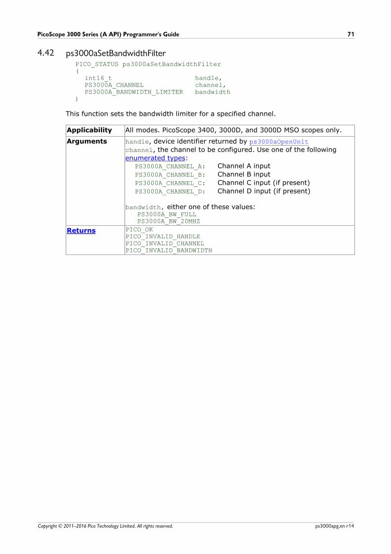
PicoScope 3000 Series (A API) Programmer's Guide 71
Copyright © 2011–2016 Pico Technology Limited. All rights reserved. ps3000apg.en r14
4.42 ps3000aSetBandwidthFilterPICO_STATUS ps3000aSetBandwidthFilter(
int16_t handle,PS3000A_CHANNEL channel,PS3000A_BANDWIDTH_LIMITER bandwidth
)
This function sets the bandwidth limiter for a specified channel.
Applicability All modes. PicoScope 3400, 3000D, and 3000D MSO scopes only.
Arguments handle, device identifier returned by ps3000aOpenUnit
channel, the channel to be configured. Use one of the following
enumerated types:PS3000A_CHANNEL_A: Channel A input
PS3000A_CHANNEL_B: Channel B input
PS3000A_CHANNEL_C: Channel C input (if present)
PS3000A_CHANNEL_D: Channel D input (if present)
bandwidth, either one of these values:PS3000A_BW_FULLPS3000A_BW_20MHZ
Returns PICO_OKPICO_INVALID_HANDLEPICO_INVALID_CHANNELPICO_INVALID_BANDWIDTH
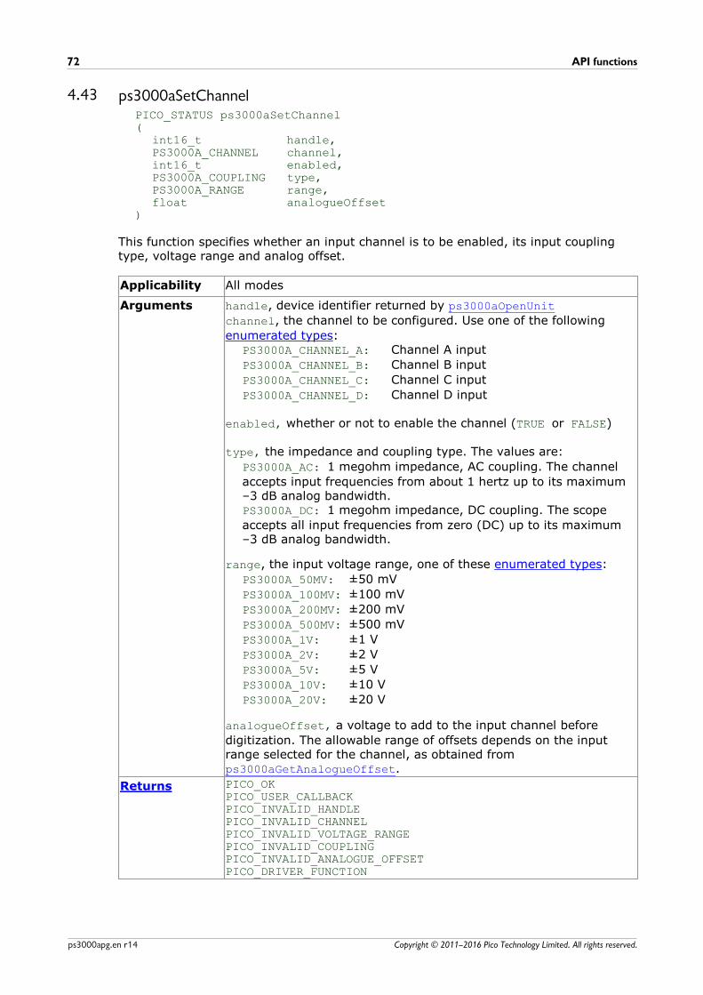
API functions72
Copyright © 2011–2016 Pico Technology Limited. All rights reserved.ps3000apg.en r14
4.43 ps3000aSetChannelPICO_STATUS ps3000aSetChannel (
int16_t handle,PS3000A_CHANNEL channel,int16_t enabled,PS3000A_COUPLING type,PS3000A_RANGE range,float analogueOffset
)
This function specifies whether an input channel is to be enabled, its input couplingtype, voltage range and analog offset.
Applicability All modes
Arguments handle, device identifier returned by ps3000aOpenUnit
channel, the channel to be configured. Use one of the following
enumerated types:PS3000A_CHANNEL_A: Channel A input
PS3000A_CHANNEL_B: Channel B input
PS3000A_CHANNEL_C: Channel C input
PS3000A_CHANNEL_D: Channel D input
enabled, whether or not to enable the channel (TRUE or FALSE)
type, the impedance and coupling type. The values are:
PS3000A_AC: 1 megohm impedance, AC coupling. The channel
accepts input frequencies from about 1 hertz up to its maximum–3 dB analog bandwidth. PS3000A_DC: 1 megohm impedance, DC coupling. The scope
accepts all input frequencies from zero (DC) up to its maximum –3 dB analog bandwidth.
range, the input voltage range, one of these enumerated types:
PS3000A_50MV: ±50 mV
PS3000A_100MV: ±100 mV
PS3000A_200MV: ±200 mV
PS3000A_500MV: ±500 mV
PS3000A_1V: ±1 V
PS3000A_2V: ±2 V
PS3000A_5V: ±5 V
PS3000A_10V: ±10 V
PS3000A_20V: ±20 V
analogueOffset, a voltage to add to the input channel before
digitization. The allowable range of offsets depends on the inputrange selected for the channel, as obtained from ps3000aGetAnalogueOffset.
Returns PICO_OKPICO_USER_CALLBACKPICO_INVALID_HANDLEPICO_INVALID_CHANNEL PICO_INVALID_VOLTAGE_RANGEPICO_INVALID_COUPLINGPICO_INVALID_ANALOGUE_OFFSETPICO_DRIVER_FUNCTION

PicoScope 3000 Series (A API) Programmer's Guide 73
Copyright © 2011–2016 Pico Technology Limited. All rights reserved. ps3000apg.en r14
4.44 ps3000aSetDataBufferPICO_STATUS ps3000aSetDataBuffer(
int16_t handle,PS3000A_CHANNEL channel,int16_t * buffer,int32_t bufferLth,uint32_t segmentIndex,PS3000A_RATIO_MODE mode
)
This function tells the driver where to store the data, either unprocessed or downsampled, that will be returned after the next call to one of the GetValues
functions. The function allows you to specify only a single buffer, so for aggregationmode, which requires two buffers, you need to call ps3000aSetDataBuffers instead.
You must allocate memory for the buffer before calling this function.
Applicability Block, rapid block and streaming modes. All downsampling modesexcept aggregation.
Arguments handle, device identifier returned by ps3000aOpenUnit
channel, the channel you want to use with the buffer. Use one of
these enumerated types:PS3000A_CHANNEL_APS3000A_CHANNEL_BPS3000A_CHANNEL_CPS3000A_CHANNEL_D
To set the buffer for a digital port, use one of these enumeratedtypes:
PS3000A_DIGITAL_PORT0 = 0x80PS3000A_DIGITAL_PORT1 = 0x81
* buffer, the location of the buffer
bufferLth, the size of the buffer array
segmentIndex, the number of the memory segment to be used
mode, the downsampling mode. See ps3000aGetValues for the
available modes, but note that a single call to ps3000aSetDataBuffer
can only associate one buffer with one downsampling mode. If youintend to call ps3000aGetValues with more than one downsampling
mode activated, then you must call ps3000aSetDataBuffer several
times to associate a separate buffer with each downsampling mode.
Returns PICO_OKPICO_INVALID_HANDLEPICO_INVALID_CHANNELPICO_RATIO_MODE_NOT_SUPPORTEDPICO_SEGMENT_OUT_OF_RANGEPICO_DRIVER_FUNCTIONPICO_INVALID_PARAMETER
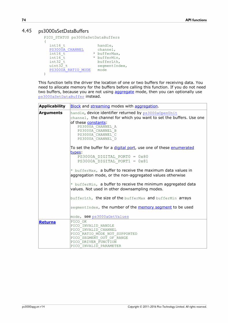
API functions74
Copyright © 2011–2016 Pico Technology Limited. All rights reserved.ps3000apg.en r14
4.45 ps3000aSetDataBuffersPICO_STATUS ps3000aSetDataBuffers(
int16_t handle,PS3000A_CHANNEL channel,int16_t * bufferMax,int16_t * bufferMin,int32_t bufferLth,uint32_t segmentIndex,PS3000A_RATIO_MODE mode
)
This function tells the driver the location of one or two buffers for receiving data. Youneed to allocate memory for the buffers before calling this function. If you do not needtwo buffers, because you are not using aggregate mode, then you can optionally useps3000aSetDataBuffer instead.
Applicability Block and streaming modes with aggregation.
Arguments handle, device identifier returned by ps3000aOpenUnit
channel, the channel for which you want to set the buffers. Use one
of these constants:PS3000A_CHANNEL_APS3000A_CHANNEL_BPS3000A_CHANNEL_CPS3000A_CHANNEL_D
To set the buffer for a digital port, use one of these enumeratedtypes:
PS3000A_DIGITAL_PORT0 = 0x80PS3000A_DIGITAL_PORT1 = 0x81
* bufferMax, a buffer to receive the maximum data values in
aggregation mode, or the non-aggregated values otherwise
* bufferMin, a buffer to receive the minimum aggregated data
values. Not used in other downsampling modes.
bufferLth, the size of the bufferMax and bufferMin arrays
segmentIndex, the number of the memory segment to be used
mode, see ps3000aGetValues
Returns PICO_OKPICO_INVALID_HANDLEPICO_INVALID_CHANNELPICO_RATIO_MODE_NOT_SUPPORTEDPICO_SEGMENT_OUT_OF_RANGEPICO_DRIVER_FUNCTIONPICO_INVALID_PARAMETER
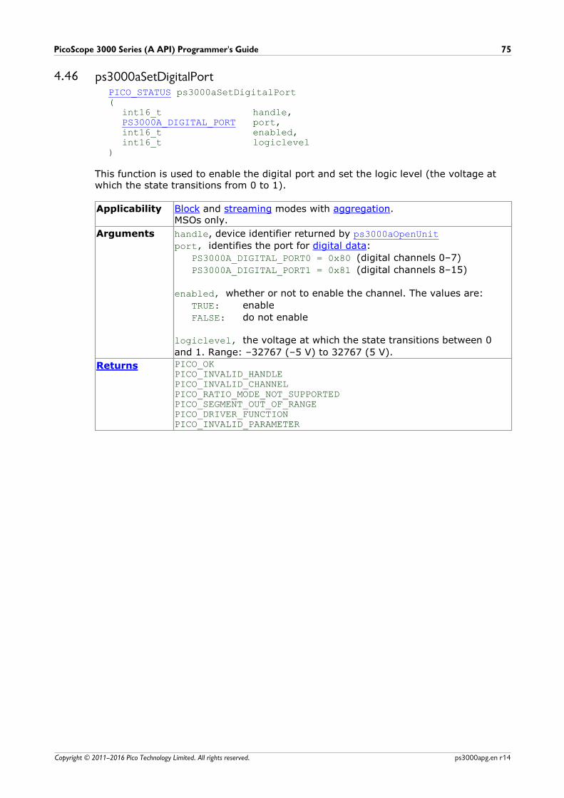
PicoScope 3000 Series (A API) Programmer's Guide 75
Copyright © 2011–2016 Pico Technology Limited. All rights reserved. ps3000apg.en r14
4.46 ps3000aSetDigitalPortPICO_STATUS ps3000aSetDigitalPort(
int16_t handle,PS3000A_DIGITAL_PORT port,int16_t enabled,int16_t logiclevel
)
This function is used to enable the digital port and set the logic level (the voltage atwhich the state transitions from 0 to 1).
Applicability Block and streaming modes with aggregation.MSOs only.
Arguments handle, device identifier returned by ps3000aOpenUnit
port, identifies the port for digital data:
PS3000A_DIGITAL_PORT0 = 0x80 (digital channels 0–7)
PS3000A_DIGITAL_PORT1 = 0x81 (digital channels 8–15)
enabled, whether or not to enable the channel. The values are:
TRUE: enable
FALSE: do not enable
logiclevel, the voltage at which the state transitions between 0
and 1. Range: –32767 (–5 V) to 32767 (5 V).
Returns PICO_OKPICO_INVALID_HANDLEPICO_INVALID_CHANNELPICO_RATIO_MODE_NOT_SUPPORTEDPICO_SEGMENT_OUT_OF_RANGEPICO_DRIVER_FUNCTIONPICO_INVALID_PARAMETER
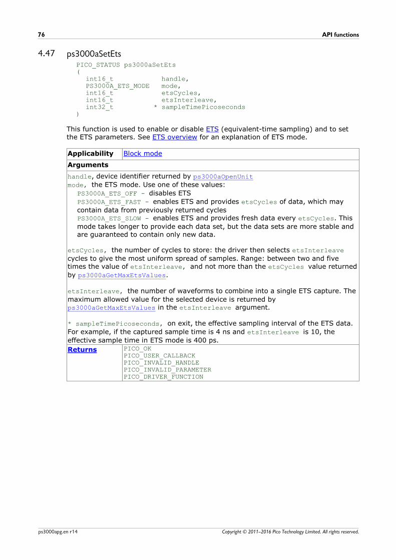
API functions76
Copyright © 2011–2016 Pico Technology Limited. All rights reserved.ps3000apg.en r14
4.47 ps3000aSetEtsPICO_STATUS ps3000aSetEts(
int16_t handle,PS3000A_ETS_MODE mode,int16_t etsCycles,int16_t etsInterleave,int32_t * sampleTimePicoseconds
)
This function is used to enable or disable ETS (equivalent-time sampling) and to setthe ETS parameters. See ETS overview for an explanation of ETS mode.
Applicability Block mode
Arguments
handle, device identifier returned by ps3000aOpenUnit
mode, the ETS mode. Use one of these values:
PS3000A_ETS_OFF - disables ETS
PS3000A_ETS_FAST - enables ETS and provides etsCycles of data, which may
contain data from previously returned cyclesPS3000A_ETS_SLOW - enables ETS and provides fresh data every etsCycles. This
mode takes longer to provide each data set, but the data sets are more stable andare guaranteed to contain only new data.
etsCycles, the number of cycles to store: the driver then selects etsInterleave
cycles to give the most uniform spread of samples. Range: between two and fivetimes the value of etsInterleave, and not more than the etsCycles value returned
by ps3000aGetMaxEtsValues.
etsInterleave, the number of waveforms to combine into a single ETS capture. The
maximum allowed value for the selected device is returned by ps3000aGetMaxEtsValues in the etsInterleave argument.
* sampleTimePicoseconds, on exit, the effective sampling interval of the ETS data.
For example, if the captured sample time is 4 ns and etsInterleave is 10, the
effective sample time in ETS mode is 400 ps.
Returns PICO_OKPICO_USER_CALLBACKPICO_INVALID_HANDLEPICO_INVALID_PARAMETERPICO_DRIVER_FUNCTION
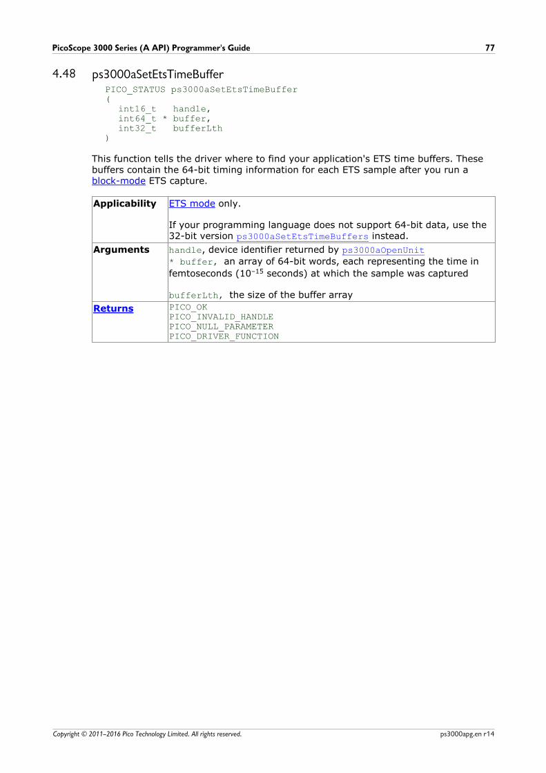
PicoScope 3000 Series (A API) Programmer's Guide 77
Copyright © 2011–2016 Pico Technology Limited. All rights reserved. ps3000apg.en r14
4.48 ps3000aSetEtsTimeBufferPICO_STATUS ps3000aSetEtsTimeBuffer(
int16_t handle,int64_t * buffer,int32_t bufferLth
)
This function tells the driver where to find your application's ETS time buffers. Thesebuffers contain the 64-bit timing information for each ETS sample after you run a block-mode ETS capture.
Applicability ETS mode only.
If your programming language does not support 64-bit data, use the32-bit version ps3000aSetEtsTimeBuffers instead.
Arguments handle, device identifier returned by ps3000aOpenUnit
* buffer, an array of 64-bit words, each representing the time in
femtoseconds (10–15 seconds) at which the sample was captured
bufferLth, the size of the buffer array
Returns PICO_OKPICO_INVALID_HANDLEPICO_NULL_PARAMETERPICO_DRIVER_FUNCTION
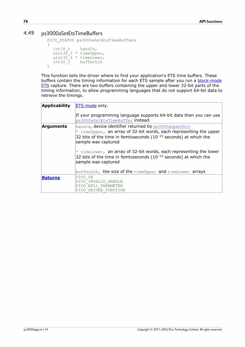
API functions78
Copyright © 2011–2016 Pico Technology Limited. All rights reserved.ps3000apg.en r14
4.49 ps3000aSetEtsTimeBuffersPICO_STATUS ps3000aSetEtsTimeBuffers(
int16_t handle,uint32_t * timeUpper,uint32_t * timeLower,int32_t bufferLth
)
This function tells the driver where to find your application's ETS time buffers. Thesebuffers contain the timing information for each ETS sample after you run a block-modeETS capture. There are two buffers containing the upper and lower 32-bit parts of thetiming information, to allow programming languages that do not support 64-bit data toretrieve the timings.
Applicability ETS mode only.
If your programming language supports 64-bit data then you can use ps3000aSetEtsTimeBuffer instead.
Arguments handle, device identifier returned by ps3000aOpenUnit
* timeUpper, an array of 32-bit words, each representing the upper
32 bits of the time in femtoseconds (10–15 seconds) at which thesample was captured
* timeLower, an array of 32-bit words, each representing the lower
32 bits of the time in femtoseconds (10–15 seconds) at which thesample was captured
bufferLth, the size of the timeUpper and timeLower arrays
Returns PICO_OKPICO_INVALID_HANDLEPICO_NULL_PARAMETERPICO_DRIVER_FUNCTION

PicoScope 3000 Series (A API) Programmer's Guide 79
Copyright © 2011–2016 Pico Technology Limited. All rights reserved. ps3000apg.en r14
4.50 ps3000aSetNoOfCapturesPICO_STATUS ps3000aSetNoOfCaptures (
int16_t handle,uint32_t nCaptures
)
This function sets the number of captures to be collected in one run of rapid blockmode. If you do not call this function before a run, the driver will capture only onewaveform. Once a value has been set, the value remains constant unless changed.
Applicability Rapid block mode
Arguments handle, device identifier returned by ps3000aOpenUnit
nCaptures, the number of waveforms to capture in one run
Returns PICO_OKPICO_INVALID_HANDLEPICO_INVALID_PARAMETERPICO_DRIVER_FUNCTION
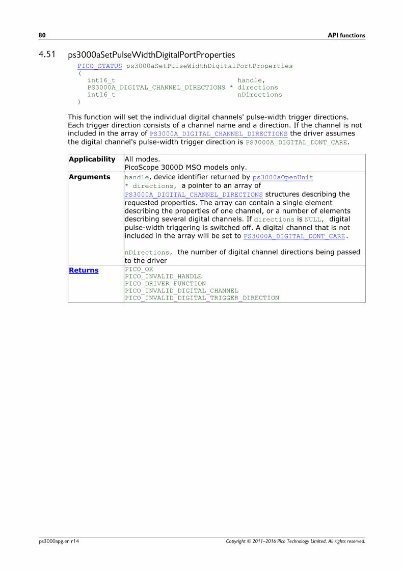
API functions80
Copyright © 2011–2016 Pico Technology Limited. All rights reserved.ps3000apg.en r14
4.51 ps3000aSetPulseWidthDigitalPortPropertiesPICO_STATUS ps3000aSetPulseWidthDigitalPortProperties(
int16_t handle,PS3000A_DIGITAL_CHANNEL_DIRECTIONS * directionsint16_t nDirections
)
This function will set the individual digital channels' pulse-width trigger directions.Each trigger direction consists of a channel name and a direction. If the channel is notincluded in the array of PS3000A_DIGITAL_CHANNEL_DIRECTIONS the driver assumes
the digital channel's pulse-width trigger direction is PS3000A_DIGITAL_DONT_CARE.
Applicability All modes.PicoScope 3000D MSO models only.
Arguments handle, device identifier returned by ps3000aOpenUnit
* directions, a pointer to an array of
PS3000A_DIGITAL_CHANNEL_DIRECTIONS structures describing the
requested properties. The array can contain a single elementdescribing the properties of one channel, or a number of elementsdescribing several digital channels. If directions is NULL, digital
pulse-width triggering is switched off. A digital channel that is notincluded in the array will be set to PS3000A_DIGITAL_DONT_CARE.
nDirections, the number of digital channel directions being passed
to the driver
Returns PICO_OKPICO_INVALID_HANDLEPICO_DRIVER_FUNCTIONPICO_INVALID_DIGITAL_CHANNELPICO_INVALID_DIGITAL_TRIGGER_DIRECTION
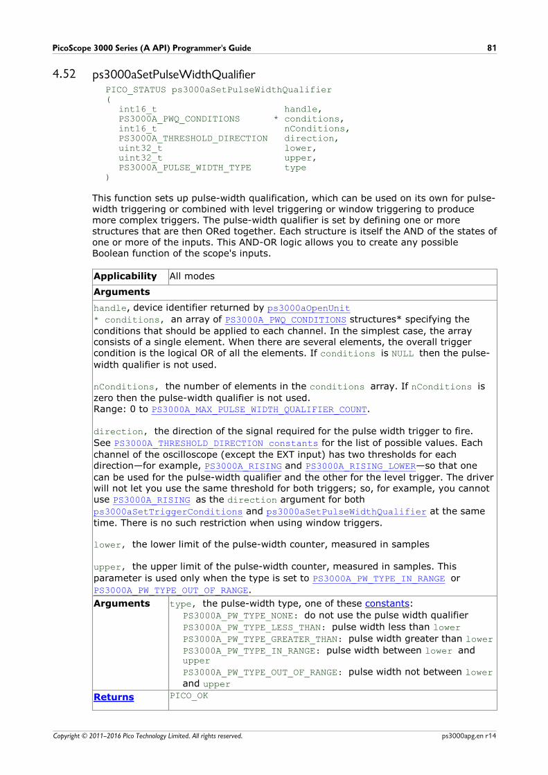
PicoScope 3000 Series (A API) Programmer's Guide 81
Copyright © 2011–2016 Pico Technology Limited. All rights reserved. ps3000apg.en r14
4.52 ps3000aSetPulseWidthQualifierPICO_STATUS ps3000aSetPulseWidthQualifier(
int16_t handle,PS3000A_PWQ_CONDITIONS * conditions,int16_t nConditions,PS3000A_THRESHOLD_DIRECTION direction,uint32_t lower,uint32_t upper,PS3000A_PULSE_WIDTH_TYPE type
)
This function sets up pulse-width qualification, which can be used on its own for pulse-width triggering or combined with level triggering or window triggering to producemore complex triggers. The pulse-width qualifier is set by defining one or morestructures that are then ORed together. Each structure is itself the AND of the states ofone or more of the inputs. This AND-OR logic allows you to create any possibleBoolean function of the scope's inputs.
Applicability All modes
Arguments
handle, device identifier returned by ps3000aOpenUnit
* conditions, an array of PS3000A_PWQ_CONDITIONS structures* specifying the
conditions that should be applied to each channel. In the simplest case, the arrayconsists of a single element. When there are several elements, the overall triggercondition is the logical OR of all the elements. If conditions is NULL then the pulse-
width qualifier is not used.
nConditions, the number of elements in the conditions array. If nConditions is
zero then the pulse-width qualifier is not used. Range: 0 to PS3000A_MAX_PULSE_WIDTH_QUALIFIER_COUNT.
direction, the direction of the signal required for the pulse width trigger to fire.
See PS3000A_THRESHOLD_DIRECTION constants for the list of possible values. Each
channel of the oscilloscope (except the EXT input) has two thresholds for eachdirection—for example, PS3000A_RISING and PS3000A_RISING_LOWER—so that one
can be used for the pulse-width qualifier and the other for the level trigger. The driverwill not let you use the same threshold for both triggers; so, for example, you cannotuse PS3000A_RISING as the direction argument for both
ps3000aSetTriggerConditions and ps3000aSetPulseWidthQualifier at the same
time. There is no such restriction when using window triggers.
lower, the lower limit of the pulse-width counter, measured in samples
upper, the upper limit of the pulse-width counter, measured in samples. This
parameter is used only when the type is set to PS3000A_PW_TYPE_IN_RANGE or
PS3000A_PW_TYPE_OUT_OF_RANGE.
Arguments type, the pulse-width type, one of these constants:
PS3000A_PW_TYPE_NONE: do not use the pulse width qualifier
PS3000A_PW_TYPE_LESS_THAN: pulse width less than lower
PS3000A_PW_TYPE_GREATER_THAN: pulse width greater than lower
PS3000A_PW_TYPE_IN_RANGE: pulse width between lower andupper
PS3000A_PW_TYPE_OUT_OF_RANGE: pulse width not between lower
and upper
Returns PICO_OK

API functions82
Copyright © 2011–2016 Pico Technology Limited. All rights reserved.ps3000apg.en r14
PICO_INVALID_HANDLEPICO_USER_CALLBACKPICO_CONDITIONSPICO_PULSE_WIDTH_QUALIFIERPICO_DRIVER_FUNCTION
*Note: using this function the driver will convert the PS3000A_PWQ_CONDITIONS into a
PS3000A_PWQ_CONDITIONS_V2 and will set the condition for digital toPS3000A_DIGITAL_DONT_CARE.
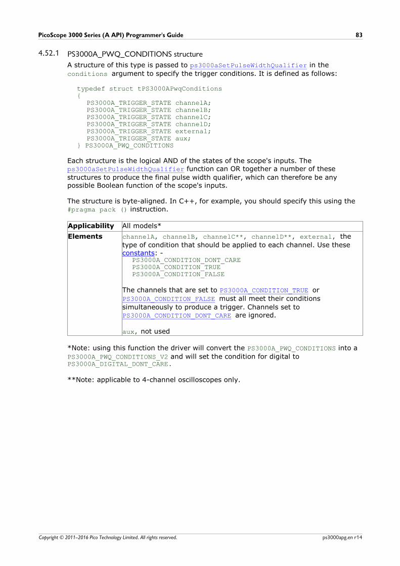
PicoScope 3000 Series (A API) Programmer's Guide 83
Copyright © 2011–2016 Pico Technology Limited. All rights reserved. ps3000apg.en r14
4.52.1 PS3000A_PWQ_CONDITIONS structure
A structure of this type is passed to ps3000aSetPulseWidthQualifier in the
conditions argument to specify the trigger conditions. It is defined as follows:
typedef struct tPS3000APwqConditions{
PS3000A_TRIGGER_STATE channelA;PS3000A_TRIGGER_STATE channelB;PS3000A_TRIGGER_STATE channelC;PS3000A_TRIGGER_STATE channelD;PS3000A_TRIGGER_STATE external;PS3000A_TRIGGER_STATE aux;
} PS3000A_PWQ_CONDITIONS
Each structure is the logical AND of the states of the scope's inputs. The ps3000aSetPulseWidthQualifier function can OR together a number of these
structures to produce the final pulse width qualifier, which can therefore be anypossible Boolean function of the scope's inputs.
The structure is byte-aligned. In C++, for example, you should specify this using the #pragma pack () instruction.
Applicability All models*
Elements channelA, channelB, channelC**, channelD**, external, the
type of condition that should be applied to each channel. Use these constants: -
PS3000A_CONDITION_DONT_CAREPS3000A_CONDITION_TRUEPS3000A_CONDITION_FALSE
The channels that are set to PS3000A_CONDITION_TRUE or
PS3000A_CONDITION_FALSE must all meet their conditions
simultaneously to produce a trigger. Channels set to PS3000A_CONDITION_DONT_CARE are ignored.
aux, not used
*Note: using this function the driver will convert the PS3000A_PWQ_CONDITIONS into a
PS3000A_PWQ_CONDITIONS_V2 and will set the condition for digital toPS3000A_DIGITAL_DONT_CARE.
**Note: applicable to 4-channel oscilloscopes only.

API functions84
Copyright © 2011–2016 Pico Technology Limited. All rights reserved.ps3000apg.en r14
4.53 ps3000aSetPulseWidthQualifierV2PICO_STATUS ps3000aSetPulseWidthQualifierV2(
int16_t handle,PS3000A_PWQ_CONDITIONS_V2 * conditions,int16_t nConditions,PS3000A_THRESHOLD_DIRECTION direction,uint32_t lower,uint32_t upper,PS3000A_PULSE_WIDTH_TYPE type
)
This function sets up pulse-width qualification, which can be used on its own for pulse-width triggering or combined with level triggering or window triggering to producemore complex triggers. The pulse-width qualifier is set by defining one or morestructures that are then ORed together. Each structure is itself the AND of the states ofone or more of the inputs. This AND-OR logic allows you to create any possibleBoolean function of the scope's inputs.
Applicability All modes
Arguments
handle, device identifier returned by ps3000aOpenUnit
* conditions, an array of PS3000A_PWQ_CONDITIONS_V2 structures specifying the
conditions that should be applied to each channel. In the simplest case, the arrayconsists of a single element. When there are several elements, the overall triggercondition is the logical OR of all the elements. If conditions is NULL then the pulse-
width qualifier is not used.
nConditions, the number of elements in the conditions array. If nConditions is
zero then the pulse-width qualifier is not used. Range: 0 to PS3000A_MAX_PULSE_WIDTH_QUALIFIER_COUNT.
direction, the direction of the signal required for the pulse width trigger to fire.
See PS3000A_THRESHOLD_DIRECTION constants for the list of possible values. Each
channel of the oscilloscope (except the EXT input) has two thresholds for eachdirection—for example, PS3000A_RISING and PS3000A_RISING_LOWER—so that one
can be used for the pulse-width qualifier and the other for the level trigger. The driverwill not let you use the same threshold for both triggers; so, for example, you cannotuse PS3000A_RISING as the direction argument for both
ps3000aSetTriggerConditionsV2 and ps3000aSetPulseWidthQualifierV2 at the
same time. There is no such restriction when using window triggers.
lower, the lower limit of the pulse-width counter, measured in samples
upper, the upper limit of the pulse-width counter, measured in samples. This
parameter is used only when the type is set to PS3000A_PW_TYPE_IN_RANGE or
PS3000A_PW_TYPE_OUT_OF_RANGE.
Arguments type, the pulse-width type, one of these constants:
PS3000A_PW_TYPE_NONE: do not use the pulse width qualifier
PS3000A_PW_TYPE_LESS_THAN: pulse width less than lower
PS3000A_PW_TYPE_GREATER_THAN: pulse width greater than lower
PS3000A_PW_TYPE_IN_RANGE: pulse width between lower andupper
PS3000A_PW_TYPE_OUT_OF_RANGE: pulse width not between lower
and upper
Returns PICO_OK

PicoScope 3000 Series (A API) Programmer's Guide 85
Copyright © 2011–2016 Pico Technology Limited. All rights reserved. ps3000apg.en r14
PICO_INVALID_HANDLEPICO_USER_CALLBACKPICO_CONDITIONSPICO_PULSE_WIDTH_QUALIFIERPICO_DRIVER_FUNCTION

API functions86
Copyright © 2011–2016 Pico Technology Limited. All rights reserved.ps3000apg.en r14
4.53.1 PS3000A_PWQ_CONDITIONS_V2 structure
A structure of this type is passed to ps3000aSetPulseWidthQualifierV2 in the
conditions argument to specify the trigger conditions. It is defined as follows:
typedef struct tPS3000APwqConditionsV2{
PS3000A_TRIGGER_STATE channelA;PS3000A_TRIGGER_STATE channelB;PS3000A_TRIGGER_STATE channelC;PS3000A_TRIGGER_STATE channelD;PS3000A_TRIGGER_STATE external;PS3000A_TRIGGER_STATE aux;PS3000A_TRIGGER_STATE digital;
} PS3000A_PWQ_CONDITIONS_V2
Each structure is the logical AND of the states of the scope's inputs. The ps3000aSetPulseWidthQualifierV2 function can OR together a number of these
structures to produce the final pulse width qualifier, which can therefore be anypossible Boolean function of the scope's inputs.
The structure is byte-aligned. In C++, for example, you should specify this using the #pragma pack () instruction.
Applicability All models
Elements channelA, channelB, channelC*, channelD*, external, the type
of condition that should be applied to each channel. Use these constants: -
PS3000A_CONDITION_DONT_CAREPS3000A_CONDITION_TRUEPS3000A_CONDITION_FALSE
The channels that are set to PS3000A_CONDITION_TRUE or
PS3000A_CONDITION_FALSE must all meet their conditions
simultaneously to produce a trigger. Channels set to PS3000A_CONDITION_DONT_CARE are ignored.
aux, not used
*Note: applicable to 4-channel analog devices only.
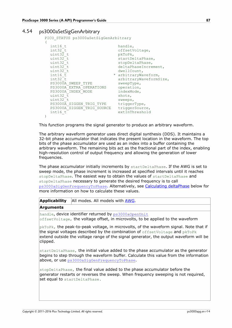
PicoScope 3000 Series (A API) Programmer's Guide 87
Copyright © 2011–2016 Pico Technology Limited. All rights reserved. ps3000apg.en r14
4.54 ps3000aSetSigGenArbitraryPICO_STATUS ps3000aSetSigGenArbitrary(
int16_t handle,int32_t offsetVoltage,uint32_t pkToPk,uint32_t startDeltaPhase,uint32_t stopDeltaPhase,uint32_t deltaPhaseIncrement,uint32_t dwellCount,int16_t * arbitraryWaveform,int32_t arbitraryWaveformSize,PS3000A_SWEEP_TYPE sweepType,PS3000A_EXTRA_OPERATIONS operation,PS3000A_INDEX_MODE indexMode,uint32_t shots,uint32_t sweeps,PS3000A_SIGGEN_TRIG_TYPE triggerType,PS3000A_SIGGEN_TRIG_SOURCE triggerSource,int16_t extInThreshold
)
This function programs the signal generator to produce an arbitrary waveform.
The arbitrary waveform generator uses direct digital synthesis (DDS). It maintains a32-bit phase accumulator that indicates the present location in the waveform. The topbits of the phase accumulator are used as an index into a buffer containing thearbitrary waveform. The remaining bits act as the fractional part of the index, enablinghigh-resolution control of output frequency and allowing the generation of lowerfrequencies.
The phase accumulator initially increments by startDeltaPhase. If the AWG is set to
sweep mode, the phase increment is increased at specified intervals until it reaches stopDeltaPhase. The easiest way to obtain the values of startDeltaPhase and
stopDeltaPhase necessary to generate the desired frequency is to call
ps3000aSigGenFrequencyToPhase. Alternatively, see Calculating deltaPhase below for
more information on how to calculate these values.
Applicability All modes. All models with AWG.
Arguments
handle, device identifier returned by ps3000aOpenUnit
offsetVoltage, the voltage offset, in microvolts, to be applied to the waveform
pkToPk, the peak-to-peak voltage, in microvolts, of the waveform signal. Note that if
the signal voltages described by the combination of offsetVoltage and pkToPk
extend outside the voltage range of the signal generator, the output waveform will beclipped.
startDeltaPhase, the initial value added to the phase accumulator as the generator
begins to step through the waveform buffer. Calculate this value from the informationabove, or use ps3000aSigGenFrequencyToPhase.
stopDeltaPhase, the final value added to the phase accumulator before the
generator restarts or reverses the sweep. When frequency sweeping is not required,set equal to startDeltaPhase.
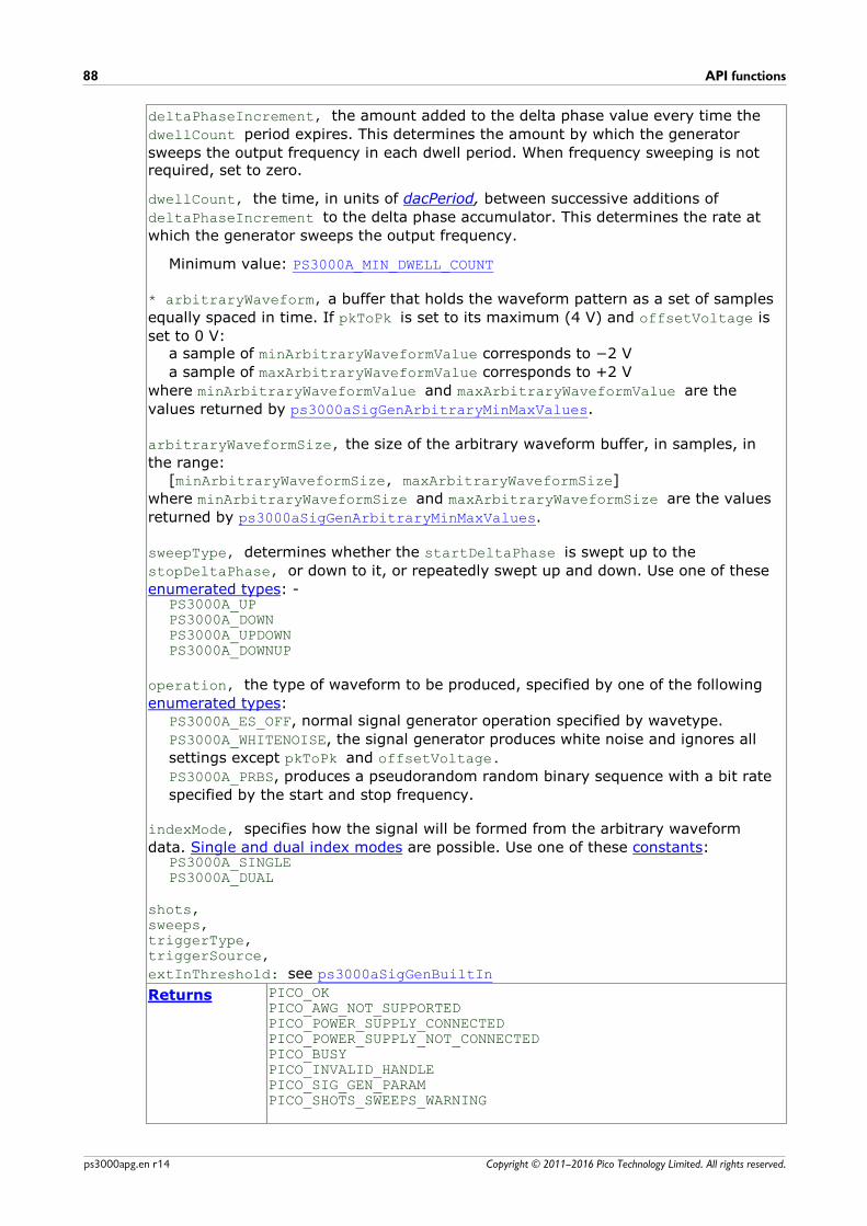
API functions88
Copyright © 2011–2016 Pico Technology Limited. All rights reserved.ps3000apg.en r14
deltaPhaseIncrement, the amount added to the delta phase value every time the
dwellCount period expires. This determines the amount by which the generator
sweeps the output frequency in each dwell period. When frequency sweeping is notrequired, set to zero.
dwellCount, the time, in units of dacPeriod, between successive additions of
deltaPhaseIncrement to the delta phase accumulator. This determines the rate at
which the generator sweeps the output frequency.
Minimum value: PS3000A_MIN_DWELL_COUNT
* arbitraryWaveform, a buffer that holds the waveform pattern as a set of samples
equally spaced in time. If pkToPk is set to its maximum (4 V) and offsetVoltage is
set to 0 V:a sample of minArbitraryWaveformValue corresponds to 2 V
a sample of maxArbitraryWaveformValue corresponds to +2 V
where minArbitraryWaveformValue and maxArbitraryWaveformValue are the
values returned by ps3000aSigGenArbitraryMinMaxValues.
arbitraryWaveformSize, the size of the arbitrary waveform buffer, in samples, in
the range:[minArbitraryWaveformSize, maxArbitraryWaveformSize]
where minArbitraryWaveformSize and maxArbitraryWaveformSize are the values
returned by ps3000aSigGenArbitraryMinMaxValues.
sweepType, determines whether the startDeltaPhase is swept up to the
stopDeltaPhase, or down to it, or repeatedly swept up and down. Use one of these
enumerated types: -PS3000A_UPPS3000A_DOWNPS3000A_UPDOWNPS3000A_DOWNUP
operation, the type of waveform to be produced, specified by one of the following
enumerated types:PS3000A_ES_OFF, normal signal generator operation specified by wavetype.
PS3000A_WHITENOISE, the signal generator produces white noise and ignores all
settings except pkToPk and offsetVoltage.
PS3000A_PRBS, produces a pseudorandom random binary sequence with a bit rate
specified by the start and stop frequency.
indexMode, specifies how the signal will be formed from the arbitrary waveform
data. Single and dual index modes are possible. Use one of these constants:PS3000A_SINGLEPS3000A_DUAL
shots,sweeps,triggerType,triggerSource,
extInThreshold: see ps3000aSigGenBuiltIn
Returns PICO_OKPICO_AWG_NOT_SUPPORTEDPICO_POWER_SUPPLY_CONNECTEDPICO_POWER_SUPPLY_NOT_CONNECTED PICO_BUSYPICO_INVALID_HANDLEPICO_SIG_GEN_PARAMPICO_SHOTS_SWEEPS_WARNING

PicoScope 3000 Series (A API) Programmer's Guide 89
Copyright © 2011–2016 Pico Technology Limited. All rights reserved. ps3000apg.en r14
PICO_NOT_RESPONDINGPICO_WARNING_EXT_THRESHOLD_CONFLICTPICO_NO_SIGNAL_GENERATOR PICO_SIGGEN_OFFSET_VOLTAGEPICO_SIGGEN_PK_TO_PKPICO_SIGGEN_OUTPUT_OVER_VOLTAGEPICO_DRIVER_FUNCTIONPICO_SIGGEN_WAVEFORM_SETUP_FAILED
4.54.1 AWG index modes
The arbitrary waveform generator supports single and dual index modes to help youmake the best use of the waveform buffer.
Single mode. The generator outputs the rawcontents of the buffer repeatedly. This mode isthe only one that can generate asymmetricalwaveforms. You can also use this mode forsymmetrical waveforms, but the dual modemakes more efficient use of the buffermemory.
Dual mode. The generator outputs thecontents of the buffer from beginning to end,and then does a second pass in the reversedirection through the buffer. This allows youto specify only the first half of a waveformwith twofold symmetry, such as a Gaussianfunction, and let the generator fill in the otherhalf.
4.54.2 Calculating deltaPhase
The arbitrary waveform generator (AWG) steps through the waveform buffer by addinga deltaPhase value between 1 and phaseAccumulatorSize–1 to the phase accumulatorevery dacPeriod (1 / dacFrequency). If the deltaPhase is constant, the generatorproduces a waveform at a constant frequency that can be calculated as follows:
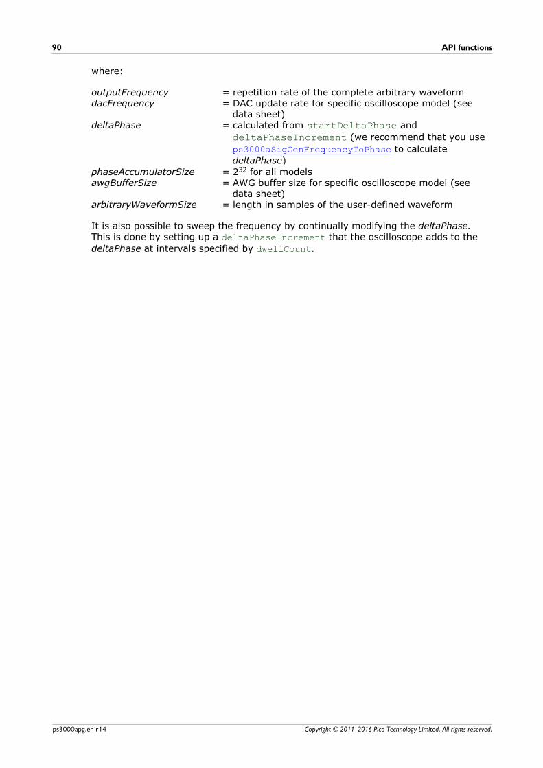
API functions90
Copyright © 2011–2016 Pico Technology Limited. All rights reserved.ps3000apg.en r14
where:
outputFrequency = repetition rate of the complete arbitrary waveformdacFrequency = DAC update rate for specific oscilloscope model (see
data sheet)deltaPhase = calculated from startDeltaPhase and
deltaPhaseIncrement (we recommend that you use
ps3000aSigGenFrequencyToPhase to calculate
deltaPhase)
phaseAccumulatorSize = 232 for all modelsawgBufferSize = AWG buffer size for specific oscilloscope model (see
data sheet)arbitraryWaveformSize = length in samples of the user-defined waveform
It is also possible to sweep the frequency by continually modifying the deltaPhase.This is done by setting up a deltaPhaseIncrement that the oscilloscope adds to the
deltaPhase at intervals specified by dwellCount.

PicoScope 3000 Series (A API) Programmer's Guide 91
Copyright © 2011–2016 Pico Technology Limited. All rights reserved. ps3000apg.en r14
4.55 ps3000aSetSigGenBuiltInPICO_STATUS ps3000aSetSigGenBuiltIn (
int16_t handle,int32_t offsetVoltage,uint32_t pkToPk,PS3000A_WAVE_TYPE waveType,float startFrequency,float stopFrequency,float increment, float dwellTime,PS3000A_SWEEP_TYPE sweepType,PS3000A_EXTRA_OPERATIONS operation,uint32_t shots,uint32_t sweeps,PS3000A_SIGGEN_TRIG_TYPE triggerType,PS3000A_SIGGEN_TRIG_SOURCE triggerSource,int16_t extInThreshold
)
This function sets up the signal generator to produce a signal from a list of built-inwaveforms. If different start and stop frequencies are specified, the device will sweepeither up, down or up and down.
Applicability All models
Arguments
handle, device identifier returned by ps3000aOpenUnit
offsetVoltage, the voltage offset, in microvolts, to be applied to the waveform
pkToPk, the peak-to-peak voltage, in microvolts, of the waveform signal. Note that if
the signal voltages described by the combination of offsetVoltage and pkToPk
extend outside the voltage range of the signal generator, the output waveform will beclipped.
waveType, the type of waveform to be generated.PS3000A_SINE sine wavePS3000A_SQUARE square wavePS3000A_TRIANGLE triangle wavePS3000A_DC_VOLTAGE DC voltageThe following waveTypes apply to B and MSO models only.PS3000A_RAMP_UP rising sawtoothPS3000A_RAMP_DOWN falling sawtoothPS3000A_SINC sin (x)/xPS3000A_GAUSSIAN GaussianPS3000A_HALF_SINE half (full-wave rectified) sine
startFrequency, the frequency that the signal generator will initially produce. For
allowable values see PS3000A_SINE_MAX_FREQUENCY and related values.
stopFrequency, the frequency at which the sweep reverses direction or returns to
the initial frequency
increment, the amount of frequency increase or decrease in sweep mode
dwellTime, the time for which the sweep stays at each frequency, in seconds
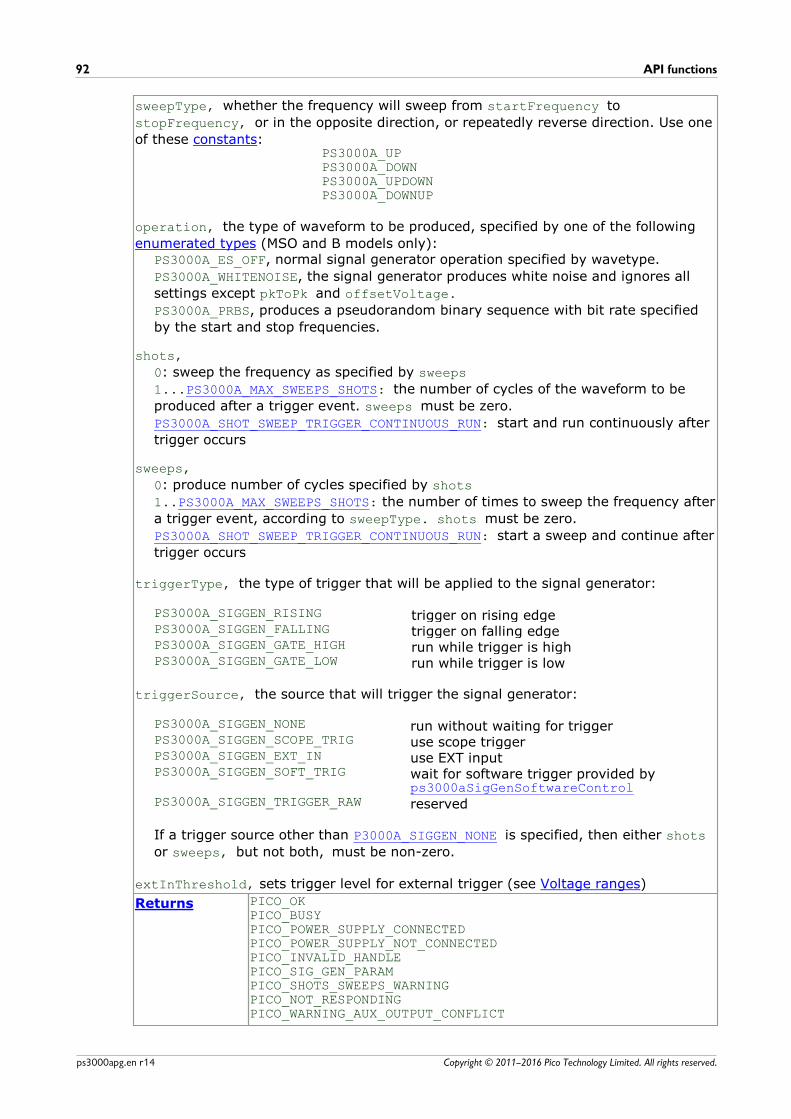
API functions92
Copyright © 2011–2016 Pico Technology Limited. All rights reserved.ps3000apg.en r14
sweepType, whether the frequency will sweep from startFrequency to
stopFrequency, or in the opposite direction, or repeatedly reverse direction. Use one
of these constants:PS3000A_UPPS3000A_DOWNPS3000A_UPDOWNPS3000A_DOWNUP
operation, the type of waveform to be produced, specified by one of the following
enumerated types (MSO and B models only):PS3000A_ES_OFF, normal signal generator operation specified by wavetype.
PS3000A_WHITENOISE, the signal generator produces white noise and ignores all
settings except pkToPk and offsetVoltage.
PS3000A_PRBS, produces a pseudorandom binary sequence with bit rate specified
by the start and stop frequencies.
shots,
0: sweep the frequency as specified by sweeps
1...PS3000A_MAX_SWEEPS_SHOTS: the number of cycles of the waveform to be
produced after a trigger event. sweeps must be zero.
PS3000A_SHOT_SWEEP_TRIGGER_CONTINUOUS_RUN: start and run continuously after
trigger occurs
sweeps,
0: produce number of cycles specified by shots
1..PS3000A_MAX_SWEEPS_SHOTS: the number of times to sweep the frequency after
a trigger event, according to sweepType. shots must be zero.
PS3000A_SHOT_SWEEP_TRIGGER_CONTINUOUS_RUN: start a sweep and continue after
trigger occurs
triggerType, the type of trigger that will be applied to the signal generator:
PS3000A_SIGGEN_RISING trigger on rising edgePS3000A_SIGGEN_FALLING trigger on falling edgePS3000A_SIGGEN_GATE_HIGH run while trigger is highPS3000A_SIGGEN_GATE_LOW run while trigger is low
triggerSource, the source that will trigger the signal generator:
PS3000A_SIGGEN_NONE run without waiting for triggerPS3000A_SIGGEN_SCOPE_TRIG use scope triggerPS3000A_SIGGEN_EXT_IN use EXT inputPS3000A_SIGGEN_SOFT_TRIG wait for software trigger provided by
ps3000aSigGenSoftwareControlPS3000A_SIGGEN_TRIGGER_RAW reserved
If a trigger source other than P3000A_SIGGEN_NONE is specified, then either shots
or sweeps, but not both, must be non-zero.
extInThreshold, sets trigger level for external trigger (see Voltage ranges)
Returns PICO_OKPICO_BUSYPICO_POWER_SUPPLY_CONNECTEDPICO_POWER_SUPPLY_NOT_CONNECTED PICO_INVALID_HANDLEPICO_SIG_GEN_PARAMPICO_SHOTS_SWEEPS_WARNINGPICO_NOT_RESPONDINGPICO_WARNING_AUX_OUTPUT_CONFLICT

PicoScope 3000 Series (A API) Programmer's Guide 93
Copyright © 2011–2016 Pico Technology Limited. All rights reserved. ps3000apg.en r14
PICO_WARNING_EXT_THRESHOLD_CONFLICTPICO_NO_SIGNAL_GENERATORPICO_SIGGEN_OFFSET_VOLTAGEPICO_SIGGEN_PK_TO_PKPICO_SIGGEN_OUTPUT_OVER_VOLTAGEPICO_DRIVER_FUNCTIONPICO_SIGGEN_WAVEFORM_SETUP_FAILEDPICO_NOT_RESPONDING
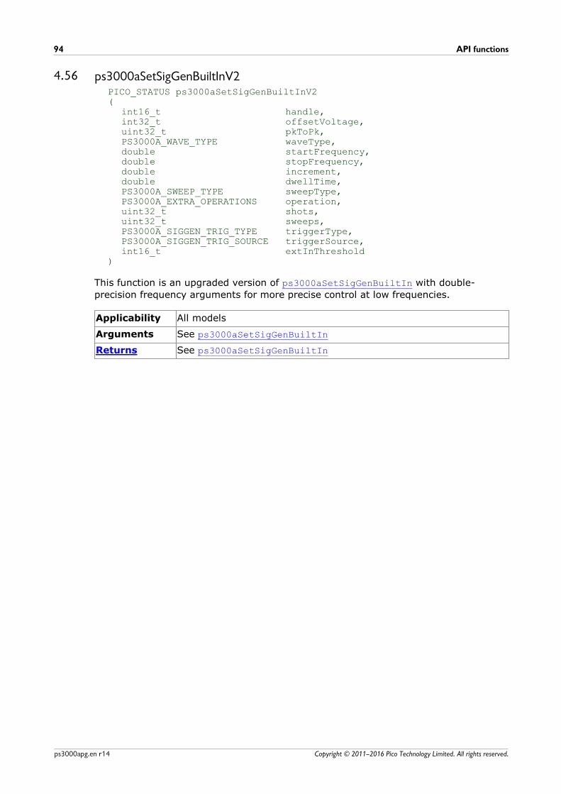
API functions94
Copyright © 2011–2016 Pico Technology Limited. All rights reserved.ps3000apg.en r14
4.56 ps3000aSetSigGenBuiltInV2PICO_STATUS ps3000aSetSigGenBuiltInV2(
int16_t handle,int32_t offsetVoltage,uint32_t pkToPk,PS3000A_WAVE_TYPE waveType,double startFrequency,double stopFrequency,double increment,double dwellTime,PS3000A_SWEEP_TYPE sweepType,PS3000A_EXTRA_OPERATIONS operation,uint32_t shots,uint32_t sweeps,PS3000A_SIGGEN_TRIG_TYPE triggerType,PS3000A_SIGGEN_TRIG_SOURCE triggerSource,int16_t extInThreshold
)
This function is an upgraded version of ps3000aSetSigGenBuiltIn with double-
precision frequency arguments for more precise control at low frequencies.
Applicability All models
Arguments See ps3000aSetSigGenBuiltIn
Returns See ps3000aSetSigGenBuiltIn
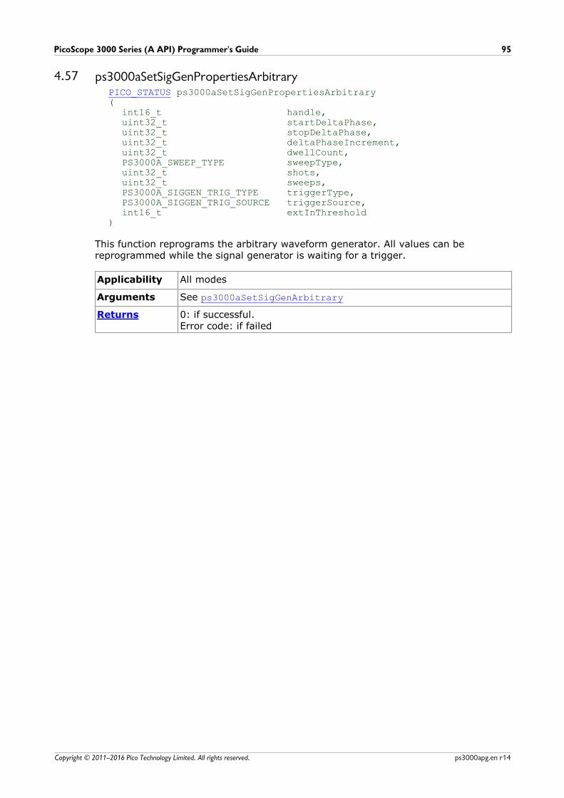
PicoScope 3000 Series (A API) Programmer's Guide 95
Copyright © 2011–2016 Pico Technology Limited. All rights reserved. ps3000apg.en r14
4.57 ps3000aSetSigGenPropertiesArbitraryPICO_STATUS ps3000aSetSigGenPropertiesArbitrary(
int16_t handle,uint32_t startDeltaPhase,uint32_t stopDeltaPhase,uint32_t deltaPhaseIncrement,uint32_t dwellCount,PS3000A_SWEEP_TYPE sweepType,uint32_t shots,uint32_t sweeps,PS3000A_SIGGEN_TRIG_TYPE triggerType,PS3000A_SIGGEN_TRIG_SOURCE triggerSource,int16_t extInThreshold
)
This function reprograms the arbitrary waveform generator. All values can bereprogrammed while the signal generator is waiting for a trigger.
Applicability All modes
Arguments See ps3000aSetSigGenArbitrary
Returns 0: if successful.Error code: if failed
API functions96
Copyright © 2011–2016 Pico Technology Limited. All rights reserved.ps3000apg.en r14
4.58 ps3000aSetSigGenPropertiesBuiltInPICO_STATUS ps3000aSetSigGenPropertiesBuiltIn(
int16_t handle,double startFrequency,double stopFrequency,double increment,double dwellTime,PS3000A_SWEEP_TYPE sweepType,uint32_t shots,uint32_t sweeps,PS3000A_SIGGEN_TRIG_TYPE triggerType,PS3000A_SIGGEN_TRIG_SOURCE triggerSource,int16_t extInThreshold
)
This function reprograms the signal generator. Values can be changed while the signalgenerator is waiting for a trigger.
Applicability All modes
Arguments See ps3000aSetSigGenBuiltIn
Returns 0: if successful.Error code: if failed
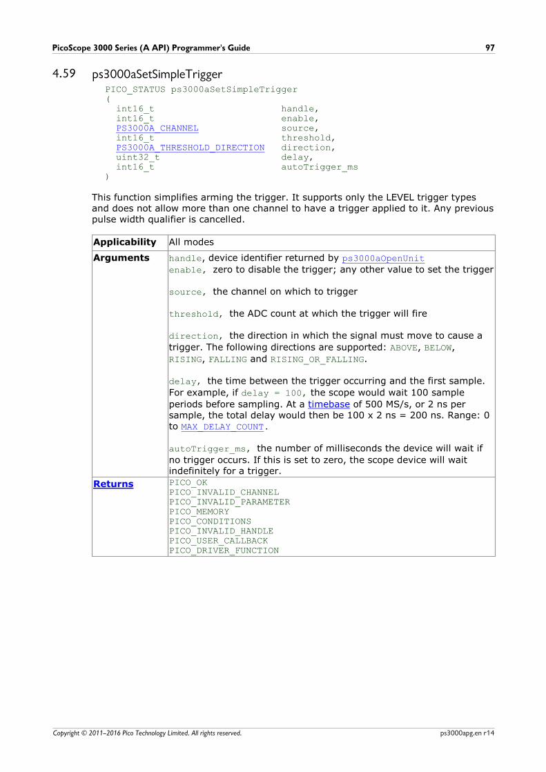
PicoScope 3000 Series (A API) Programmer's Guide 97
Copyright © 2011–2016 Pico Technology Limited. All rights reserved. ps3000apg.en r14
4.59 ps3000aSetSimpleTriggerPICO_STATUS ps3000aSetSimpleTrigger( int16_t handle, int16_t enable, PS3000A_CHANNEL source, int16_t threshold, PS3000A_THRESHOLD_DIRECTION direction, uint32_t delay, int16_t autoTrigger_ms)
This function simplifies arming the trigger. It supports only the LEVEL trigger typesand does not allow more than one channel to have a trigger applied to it. Any previouspulse width qualifier is cancelled.
Applicability All modes
Arguments handle, device identifier returned by ps3000aOpenUnit
enable, zero to disable the trigger; any other value to set the trigger
source, the channel on which to trigger
threshold, the ADC count at which the trigger will fire
direction, the direction in which the signal must move to cause a
trigger. The following directions are supported: ABOVE, BELOW,
RISING, FALLING and RISING_OR_FALLING.
delay, the time between the trigger occurring and the first sample.
For example, if delay = 100, the scope would wait 100 sample
periods before sampling. At a timebase of 500 MS/s, or 2 ns persample, the total delay would then be 100 x 2 ns = 200 ns. Range: 0to MAX_DELAY_COUNT.
autoTrigger_ms, the number of milliseconds the device will wait if
no trigger occurs. If this is set to zero, the scope device will waitindefinitely for a trigger.
Returns PICO_OKPICO_INVALID_CHANNELPICO_INVALID_PARAMETERPICO_MEMORYPICO_CONDITIONSPICO_INVALID_HANDLEPICO_USER_CALLBACKPICO_DRIVER_FUNCTION

API functions98
Copyright © 2011–2016 Pico Technology Limited. All rights reserved.ps3000apg.en r14
4.60 ps3000aSetTriggerChannelConditionsPICO_STATUS ps3000aSetTriggerChannelConditions(
int16_t handle,PS3000A_TRIGGER_CONDITIONS * conditions,int16_t nConditions
)
This function sets up trigger conditions on the scope's inputs. The trigger is defined byone or more PS3000A_TRIGGER_CONDITIONS structures that are then ORed together.
Each structure is itself the AND of the states of one or more of the inputs. This AND-OR logic allows you to create any possible Boolean function of the scope's inputs.
If complex triggering is not required, use ps3000aSetSimpleTrigger.
Applicability All modes
Arguments handle, device identifier returned by ps3000aOpenUnit
* conditions, an array of PS3000A_TRIGGER_CONDITIONS
structures* specifying the conditions that should be applied to eachchannel. In the simplest case, the array consists of a single element.When there is more than one element, the overall trigger condition isthe logical OR of all the elements.
nConditions, the number of elements in the conditions array. If
nConditions is zero then triggering is switched off.
Returns PICO_OKPICO_INVALID_HANDLEPICO_USER_CALLBACKPICO_CONDITIONSPICO_MEMORYPICO_DRIVER_FUNCTION
*Note: using this function the driver will convert the PS3000A_TRIGGER_CONDITIONS
into a PS3000A_TRIGGER_CONDITIONS_V2 and will set the condition for digital toPS3000A_DIGITAL_DONT_CARE.
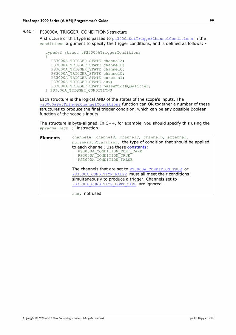
PicoScope 3000 Series (A API) Programmer's Guide 99
Copyright © 2011–2016 Pico Technology Limited. All rights reserved. ps3000apg.en r14
4.60.1 PS3000A_TRIGGER_CONDITIONS structure
A structure of this type is passed to ps3000aSetTriggerChannelConditions in the
conditions argument to specify the trigger conditions, and is defined as follows: -
typedef struct tPS3000ATriggerConditions{
PS3000A_TRIGGER_STATE channelA;PS3000A_TRIGGER_STATE channelB;PS3000A_TRIGGER_STATE channelC;PS3000A_TRIGGER_STATE channelD;PS3000A_TRIGGER_STATE external;PS3000A_TRIGGER_STATE aux;PS3000A_TRIGGER_STATE pulseWidthQualifier;
} PS3000A_TRIGGER_CONDITIONS
Each structure is the logical AND of the states of the scope's inputs. The ps3000aSetTriggerChannelConditions function can OR together a number of these
structures to produce the final trigger condition, which can be any possible Booleanfunction of the scope's inputs.
The structure is byte-aligned. In C++, for example, you should specify this using the #pragma pack () instruction.
Elements channelA, channelB, channelC, channelD, external,
pulseWidthQualifier, the type of condition that should be applied
to each channel. Use these constants:PS3000A_CONDITION_DONT_CAREPS3000A_CONDITION_TRUEPS3000A_CONDITION_FALSE
The channels that are set to PS3000A_CONDITION_TRUE or
PS3000A_CONDITION_FALSE must all meet their conditions
simultaneously to produce a trigger. Channels set to PS3000A_CONDITION_DONT_CARE are ignored.
aux, not used
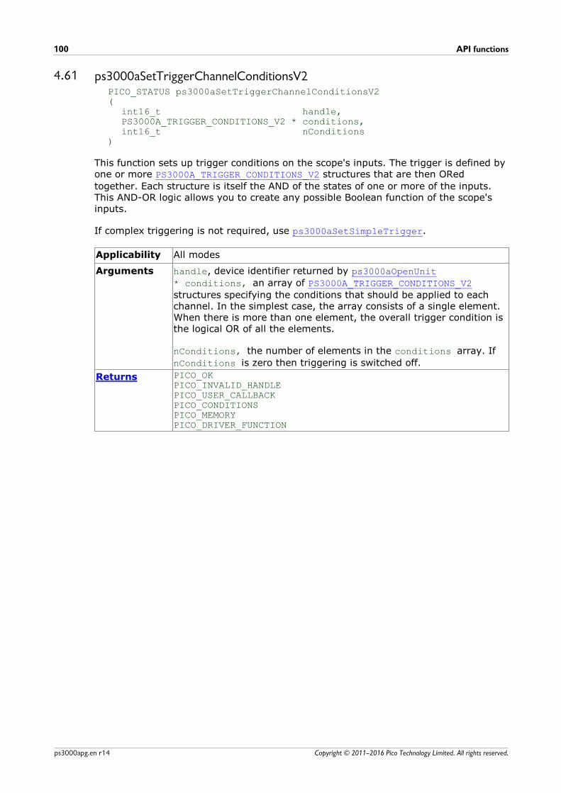
API functions100
Copyright © 2011–2016 Pico Technology Limited. All rights reserved.ps3000apg.en r14
4.61 ps3000aSetTriggerChannelConditionsV2PICO_STATUS ps3000aSetTriggerChannelConditionsV2(
int16_t handle,PS3000A_TRIGGER_CONDITIONS_V2 * conditions,int16_t nConditions
)
This function sets up trigger conditions on the scope's inputs. The trigger is defined byone or more PS3000A_TRIGGER_CONDITIONS_V2 structures that are then ORed
together. Each structure is itself the AND of the states of one or more of the inputs.This AND-OR logic allows you to create any possible Boolean function of the scope'sinputs.
If complex triggering is not required, use ps3000aSetSimpleTrigger.
Applicability All modes
Arguments handle, device identifier returned by ps3000aOpenUnit
* conditions, an array of PS3000A_TRIGGER_CONDITIONS_V2
structures specifying the conditions that should be applied to eachchannel. In the simplest case, the array consists of a single element.When there is more than one element, the overall trigger condition isthe logical OR of all the elements.
nConditions, the number of elements in the conditions array. If
nConditions is zero then triggering is switched off.
Returns PICO_OKPICO_INVALID_HANDLEPICO_USER_CALLBACKPICO_CONDITIONSPICO_MEMORYPICO_DRIVER_FUNCTION

PicoScope 3000 Series (A API) Programmer's Guide 101
Copyright © 2011–2016 Pico Technology Limited. All rights reserved. ps3000apg.en r14
4.61.1 PS3000A_TRIGGER_CONDITIONS_V2 structure
A structure of this type is passed to ps3000aSetTriggerChannelConditionsV2 in the
conditions argument to specify the trigger conditions, and is defined as follows: -
typedef struct tPS3000ATriggerConditionsV2{
PS3000A_TRIGGER_STATE channelA;PS3000A_TRIGGER_STATE channelB;PS3000A_TRIGGER_STATE channelC;PS3000A_TRIGGER_STATE channelD;PS3000A_TRIGGER_STATE external;PS3000A_TRIGGER_STATE aux;PS3000A_TRIGGER_STATE pulseWidthQualifier;PS3000A_TRIGGER_STATE digital;
} PS3000A_TRIGGER_CONDITIONS_V2;
Each structure is the logical AND of the states of the scope's inputs. ps3000aSetTriggerChannelConditionsV2 can OR together a number of these
structures to produce the final trigger condition, which can be any possible Booleanfunction of the scope's inputs.
The structure is byte-aligned. In C++, for example, you should specify this using the #pragma pack() instruction.
Elements channelA, channelB, channelC, channelD, external,
pulseWidthQualifier, the type of condition that should be applied
to each channel. Use these constants:PS3000A_CONDITION_DONT_CAREPS3000A_CONDITION_TRUEPS3000A_CONDITION_FALSE
The channels that are set to PS3000A_CONDITION_TRUE or
PS3000A_CONDITION_FALSE must all meet their conditions
simultaneously to produce a trigger. Channels set to PS3000A_CONDITION_DONT_CARE are ignored.
aux, not used
API functions102
Copyright © 2011–2016 Pico Technology Limited. All rights reserved.ps3000apg.en r14
4.62 ps3000aSetTriggerChannelDirectionsPICO_STATUS ps3000aSetTriggerChannelDirections(
int16_t handle,PS3000A_THRESHOLD_DIRECTION channelA,PS3000A_THRESHOLD_DIRECTION channelB,PS3000A_THRESHOLD_DIRECTION channelC,PS3000A_THRESHOLD_DIRECTION channelD,PS3000A_THRESHOLD_DIRECTION ext,PS3000A_THRESHOLD_DIRECTION aux
)
This function sets the direction of the trigger for each channel.
Applicability All modes
Arguments handle, device identifier returned by ps3000aOpenUnit
channelA, channelB, channelC, channelD, ext, the direction in
which the signal must pass through the threshold to activate thetrigger. See the table below for allowable values. If using a leveltrigger in conjunction with a pulse-width trigger, see the descriptionof the direction argument to ps3000aSetPulseWidthQualifierV2
for more information.
aux, not used
Returns PICO_OKPICO_INVALID_HANDLEPICO_USER_CALLBACKPICO_INVALID_PARAMETER
PS3000A_THRESHOLD_DIRECTION constants
PS3000A_ABOVE for gated triggers: above the upper thresholdPS3000A_ABOVE_LOWER for gated triggers: above the lower thresholdPS3000A_BELOW for gated triggers: below the upper thresholdPS3000A_BELOW_LOWER for gated triggers: below the lower thresholdPS3000A_RISING for threshold triggers: rising edge, using upper
thresholdPS3000A_RISING_LOWER for threshold triggers: rising edge, using lower
thresholdPS3000A_FALLING for threshold triggers: falling edge, using upper
thresholdPS3000A_FALLING_LOWER for threshold triggers: falling edge, using lower
thresholdPS3000A_RISING_OR_FALLING for threshold triggers: either edgePS3000A_INSIDE for window-qualified triggers: inside windowPS3000A_OUTSIDE for window-qualified triggers: outside windowPS3000A_ENTER for window triggers: entering the windowPS3000A_EXIT for window triggers: leaving the windowPS3000A_ENTER_OR_EXIT for window triggers: either entering or leaving
the windowPS3000A_POSITIVE_RUNT for window-qualified triggersPS3000A_NEGATIVE_RUNT for window-qualified triggersPS3000A_NONE no trigger
PicoScope 3000 Series (A API) Programmer's Guide 103
Copyright © 2011–2016 Pico Technology Limited. All rights reserved. ps3000apg.en r14
4.63 ps3000aSetTriggerChannelPropertiesPICO_STATUS ps3000aSetTriggerChannelProperties(
int16_t handle,PS3000A_TRIGGER_CHANNEL_PROPERTIES * channelProperties,int16_t nChannelProperties,int16_t auxOutputEnable,int32_t autoTriggerMilliseconds
)
This function is used to enable or disable triggering and set its parameters.
Applicability All modes
Arguments handle, device identifier returned by ps3000aOpenUnit
* channelProperties, a pointer to an array of
TRIGGER_CHANNEL_PROPERTIES structures describing the requested
properties. The array can contain a single element describing theproperties of one channel, or a number of elements describing severalchannels. If NULL is passed, triggering is switched off.
nChannelProperties, the size of the channelProperties array. If
zero, triggering is switched off.
auxOutputEnable, not used
autoTriggerMilliseconds, the time in milliseconds for which the
scope device will wait before collecting data if no trigger event occurs.If this is set to zero, the scope device will wait indefinitely for atrigger.
Returns PICO_OKPICO_INVALID_HANDLEPICO_USER_CALLBACKPICO_TRIGGER_ERRORPICO_MEMORYPICO_INVALID_TRIGGER_PROPERTYPICO_DRIVER_FUNCTIONPICO_INVALID_PARAMETER
API functions104
Copyright © 2011–2016 Pico Technology Limited. All rights reserved.ps3000apg.en r14
4.63.1 PS3000A_TRIGGER_CHANNEL_PROPERTIES structure
A structure of this type is passed to ps3000aSetTriggerChannelProperties in the
channelProperties argument to specify the trigger mechanism, and is defined as
follows: -
typedef struct tPS3000ATriggerChannelProperties{
int16_t thresholdUpper;uint16_t thresholdUpperHysteresis;int16_t thresholdLower;uint16_t thresholdLowerHysteresis;PS3000A_CHANNEL channel;PS3000A_THRESHOLD_MODE thresholdMode;
} PS3000A_TRIGGER_CHANNEL_PROPERTIES
The structure is byte-aligned. In C++, for example, you should specify this using the #pragma pack() instruction.
Upper and lower thresholds
The digital triggering hardware in your PicoScope has two independent triggerthresholds called upper and lower. For some trigger types you can freely choose whichthreshold to use. The table in ps3000aSetTriggerChannelDirections shows which
thresholds are available for use with which trigger types. Dual thresholds are used forpulse-width triggering, when one threshold applies to the level trigger and the other tothe pulse-width qualifier; and for window triggering, when the two thresholds definethe upper and lower limits of the window.
Each threshold has its own trigger and hysteresis settings.
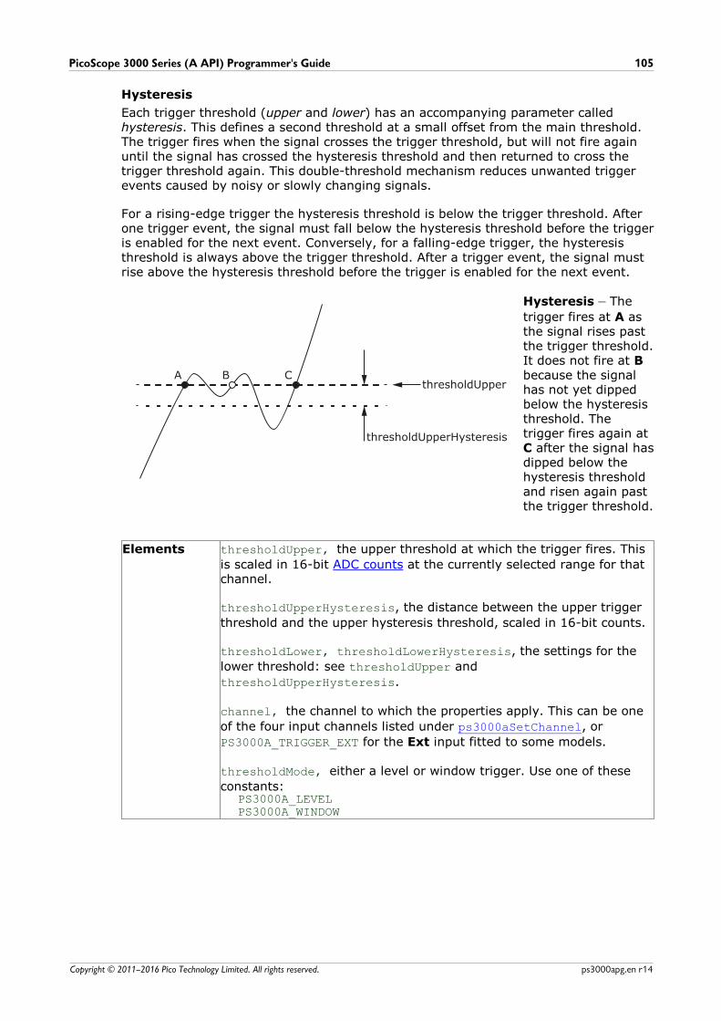
PicoScope 3000 Series (A API) Programmer's Guide 105
Copyright © 2011–2016 Pico Technology Limited. All rights reserved. ps3000apg.en r14
Hysteresis
Each trigger threshold (upper and lower) has an accompanying parameter calledhysteresis. This defines a second threshold at a small offset from the main threshold.The trigger fires when the signal crosses the trigger threshold, but will not fire againuntil the signal has crossed the hysteresis threshold and then returned to cross thetrigger threshold again. This double-threshold mechanism reduces unwanted triggerevents caused by noisy or slowly changing signals.
For a rising-edge trigger the hysteresis threshold is below the trigger threshold. Afterone trigger event, the signal must fall below the hysteresis threshold before the triggeris enabled for the next event. Conversely, for a falling-edge trigger, the hysteresisthreshold is always above the trigger threshold. After a trigger event, the signal mustrise above the hysteresis threshold before the trigger is enabled for the next event.
Hysteresis – The
trigger fires at A asthe signal rises pastthe trigger threshold.It does not fire at Bbecause the signalhas not yet dippedbelow the hysteresisthreshold. Thetrigger fires again at C after the signal hasdipped below thehysteresis thresholdand risen again pastthe trigger threshold.
Elements thresholdUpper, the upper threshold at which the trigger fires. This
is scaled in 16-bit ADC counts at the currently selected range for thatchannel.
thresholdUpperHysteresis, the distance between the upper trigger
threshold and the upper hysteresis threshold, scaled in 16-bit counts.
thresholdLower, thresholdLowerHysteresis, the settings for the
lower threshold: see thresholdUpper and
thresholdUpperHysteresis.
channel, the channel to which the properties apply. This can be one
of the four input channels listed under ps3000aSetChannel, or
PS3000A_TRIGGER_EXT for the Ext input fitted to some models.
thresholdMode, either a level or window trigger. Use one of these
constants:PS3000A_LEVELPS3000A_WINDOW

API functions106
Copyright © 2011–2016 Pico Technology Limited. All rights reserved.ps3000apg.en r14
4.64 ps3000aSetTriggerDelayPICO_STATUS ps3000aSetTriggerDelay(
int16_t handle,uint32_t delay
)
This function sets the post-trigger delay, which causes capture to start a defined timeafter the trigger event.
Applicability All modes (but delay is ignored in streaming mode)
Arguments handle, device identifier returned by ps3000aOpenUnit
delay, the time between the trigger occurring and the first sample.
For example, if delay=100 then the scope would wait 100 sample
periods before sampling. At a timebase of 500 MS/s, or 2 ns persample, the total delay would be 100 x 2 ns = 200 ns.
Range: 0 to MAX_DELAY_COUNT
Returns PICO_OKPICO_INVALID_HANDLEPICO_USER_CALLBACKPICO_DRIVER_FUNCTION

PicoScope 3000 Series (A API) Programmer's Guide 107
Copyright © 2011–2016 Pico Technology Limited. All rights reserved. ps3000apg.en r14
4.65 ps3000aSetTriggerDigitalPortPropertiesPICO_STATUS ps3000aSetTriggerDigitalPortProperties(
int16_t handle,PS3000A_DIGITAL_CHANNEL_DIRECTIONS * directionsint16_t nDirections
)
This function will set the individual digital channels' trigger directions. Each triggerdirection consists of a channel name and a direction. If the channel is not included inthe array of PS3000A_DIGITAL_CHANNEL_DIRECTIONS the driver assumes the digital
channel's trigger direction is PS3000A_DIGITAL_DONT_CARE.
Applicability PicoScope 3000D MSO models only.
Arguments handle, device identifier returned by ps3000aOpenUnit
* directions, a pointer to an array of
PS3000A_DIGITAL_CHANNEL_DIRECTIONS structures describing the
requested properties. The array can contain a single elementdescribing the properties of one channel, or a number of elementsdescribing several digital channels. If directions is NULL, digital
triggering is switched off. A digital channel that is not included in thearray will be set to PS3000A_DIGITAL_DONT_CARE. The outcomes of
all the DIRECTIONS structures in the array are ORed together to
produce the final trigger signal.
nDirections, the number of digital channel directions being passed
to the driver
Returns PICO_OKPICO_INVALID_HANDLEPICO_DRIVER_FUNCTIONPICO_INVALID_DIGITAL_CHANNELPICO_INVALID_DIGITAL_TRIGGER_DIRECTION
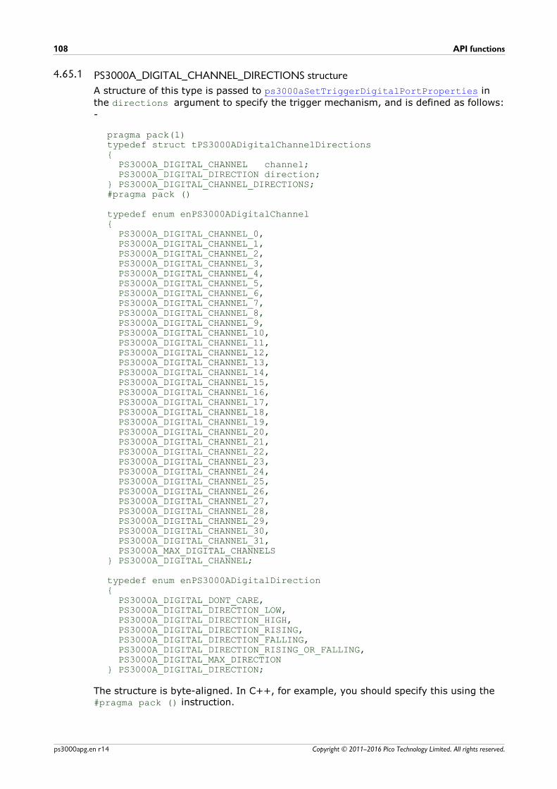
API functions108
Copyright © 2011–2016 Pico Technology Limited. All rights reserved.ps3000apg.en r14
4.65.1 PS3000A_DIGITAL_CHANNEL_DIRECTIONS structure
A structure of this type is passed to ps3000aSetTriggerDigitalPortProperties in
the directions argument to specify the trigger mechanism, and is defined as follows:
-
pragma pack(1)typedef struct tPS3000ADigitalChannelDirections{ PS3000A_DIGITAL_CHANNEL channel; PS3000A_DIGITAL_DIRECTION direction;} PS3000A_DIGITAL_CHANNEL_DIRECTIONS;#pragma pack ()
typedef enum enPS3000ADigitalChannel{ PS3000A_DIGITAL_CHANNEL_0, PS3000A_DIGITAL_CHANNEL_1, PS3000A_DIGITAL_CHANNEL_2, PS3000A_DIGITAL_CHANNEL_3, PS3000A_DIGITAL_CHANNEL_4, PS3000A_DIGITAL_CHANNEL_5, PS3000A_DIGITAL_CHANNEL_6, PS3000A_DIGITAL_CHANNEL_7, PS3000A_DIGITAL_CHANNEL_8, PS3000A_DIGITAL_CHANNEL_9, PS3000A_DIGITAL_CHANNEL_10, PS3000A_DIGITAL_CHANNEL_11, PS3000A_DIGITAL_CHANNEL_12, PS3000A_DIGITAL_CHANNEL_13, PS3000A_DIGITAL_CHANNEL_14, PS3000A_DIGITAL_CHANNEL_15, PS3000A_DIGITAL_CHANNEL_16, PS3000A_DIGITAL_CHANNEL_17, PS3000A_DIGITAL_CHANNEL_18, PS3000A_DIGITAL_CHANNEL_19, PS3000A_DIGITAL_CHANNEL_20, PS3000A_DIGITAL_CHANNEL_21, PS3000A_DIGITAL_CHANNEL_22, PS3000A_DIGITAL_CHANNEL_23, PS3000A_DIGITAL_CHANNEL_24, PS3000A_DIGITAL_CHANNEL_25, PS3000A_DIGITAL_CHANNEL_26, PS3000A_DIGITAL_CHANNEL_27, PS3000A_DIGITAL_CHANNEL_28, PS3000A_DIGITAL_CHANNEL_29, PS3000A_DIGITAL_CHANNEL_30, PS3000A_DIGITAL_CHANNEL_31, PS3000A_MAX_DIGITAL_CHANNELS} PS3000A_DIGITAL_CHANNEL;
typedef enum enPS3000ADigitalDirection{ PS3000A_DIGITAL_DONT_CARE, PS3000A_DIGITAL_DIRECTION_LOW, PS3000A_DIGITAL_DIRECTION_HIGH, PS3000A_DIGITAL_DIRECTION_RISING, PS3000A_DIGITAL_DIRECTION_FALLING, PS3000A_DIGITAL_DIRECTION_RISING_OR_FALLING, PS3000A_DIGITAL_MAX_DIRECTION} PS3000A_DIGITAL_DIRECTION;
The structure is byte-aligned. In C++, for example, you should specify this using the #pragma pack () instruction.
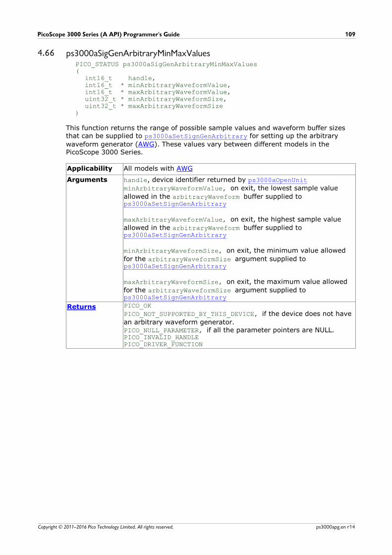
PicoScope 3000 Series (A API) Programmer's Guide 109
Copyright © 2011–2016 Pico Technology Limited. All rights reserved. ps3000apg.en r14
4.66 ps3000aSigGenArbitraryMinMaxValuesPICO_STATUS ps3000aSigGenArbitraryMinMaxValues(
int16_t handle,int16_t * minArbitraryWaveformValue,int16_t * maxArbitraryWaveformValue,uint32_t * minArbitraryWaveformSize,uint32_t * maxArbitraryWaveformSize
)
This function returns the range of possible sample values and waveform buffer sizesthat can be supplied to ps3000aSetSignGenArbitrary for setting up the arbitrary
waveform generator (AWG). These values vary between different models in thePicoScope 3000 Series.
Applicability All models with AWG
Arguments handle, device identifier returned by ps3000aOpenUnit
minArbitraryWaveformValue, on exit, the lowest sample value
allowed in the arbitraryWaveform buffer supplied tops3000aSetSignGenArbitrary
maxArbitraryWaveformValue, on exit, the highest sample value
allowed in the arbitraryWaveform buffer supplied tops3000aSetSignGenArbitrary
minArbitraryWaveformSize, on exit, the minimum value allowed
for the arbitraryWaveformSize argument supplied tops3000aSetSignGenArbitrary
maxArbitraryWaveformSize, on exit, the maximum value allowed
for the arbitraryWaveformSize argument supplied tops3000aSetSignGenArbitrary
Returns PICO_OK
PICO_NOT_SUPPORTED_BY_THIS_DEVICE, if the device does not have
an arbitrary waveform generator.PICO_NULL_PARAMETER, if all the parameter pointers are NULL.PICO_INVALID_HANDLEPICO_DRIVER_FUNCTION
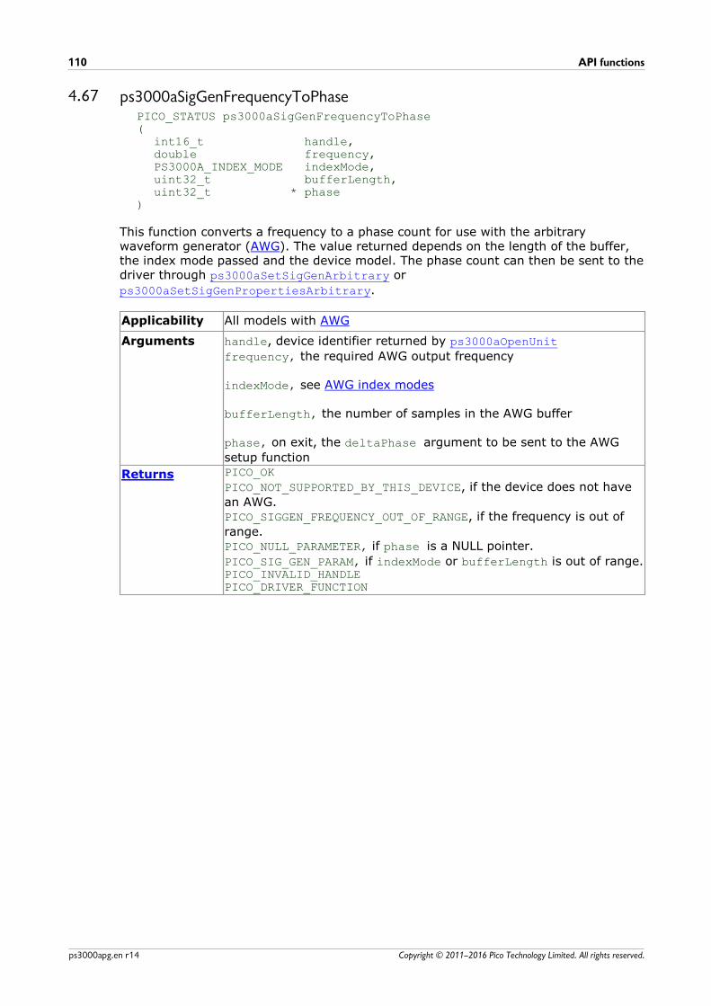
API functions110
Copyright © 2011–2016 Pico Technology Limited. All rights reserved.ps3000apg.en r14
4.67 ps3000aSigGenFrequencyToPhasePICO_STATUS ps3000aSigGenFrequencyToPhase(
int16_t handle,double frequency,PS3000A_INDEX_MODE indexMode,uint32_t bufferLength,uint32_t * phase
)
This function converts a frequency to a phase count for use with the arbitrarywaveform generator (AWG). The value returned depends on the length of the buffer,the index mode passed and the device model. The phase count can then be sent to thedriver through ps3000aSetSigGenArbitrary or
ps3000aSetSigGenPropertiesArbitrary.
Applicability All models with AWG
Arguments handle, device identifier returned by ps3000aOpenUnit
frequency, the required AWG output frequency
indexMode, see AWG index modes
bufferLength, the number of samples in the AWG buffer
phase, on exit, the deltaPhase argument to be sent to the AWG
setup function
Returns PICO_OK
PICO_NOT_SUPPORTED_BY_THIS_DEVICE, if the device does not have
an AWG.PICO_SIGGEN_FREQUENCY_OUT_OF_RANGE, if the frequency is out of
range.PICO_NULL_PARAMETER, if phase is a NULL pointer.
PICO_SIG_GEN_PARAM, if indexMode or bufferLength is out of range.PICO_INVALID_HANDLEPICO_DRIVER_FUNCTION
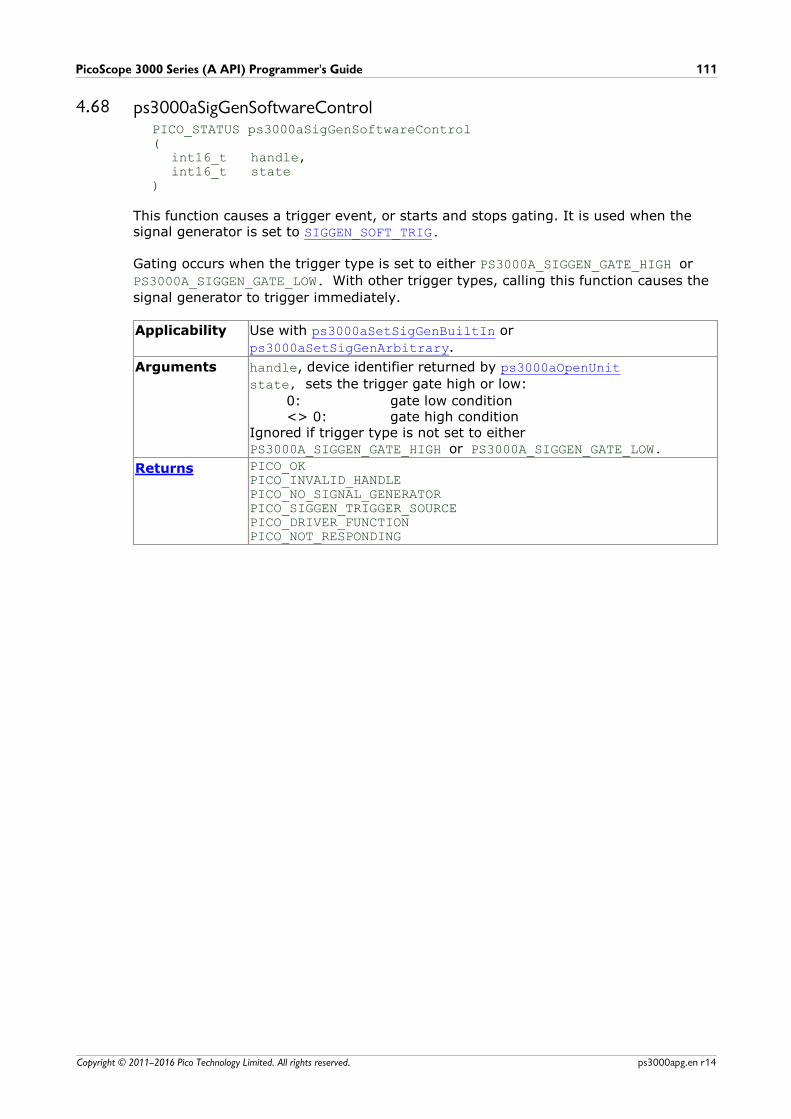
PicoScope 3000 Series (A API) Programmer's Guide 111
Copyright © 2011–2016 Pico Technology Limited. All rights reserved. ps3000apg.en r14
4.68 ps3000aSigGenSoftwareControlPICO_STATUS ps3000aSigGenSoftwareControl(
int16_t handle,int16_t state
)
This function causes a trigger event, or starts and stops gating. It is used when thesignal generator is set to SIGGEN_SOFT_TRIG.
Gating occurs when the trigger type is set to either PS3000A_SIGGEN_GATE_HIGH or
PS3000A_SIGGEN_GATE_LOW. With other trigger types, calling this function causes the
signal generator to trigger immediately.
Applicability Use with ps3000aSetSigGenBuiltIn or
ps3000aSetSigGenArbitrary.
Arguments handle, device identifier returned by ps3000aOpenUnit
state, sets the trigger gate high or low:
0: gate low condition<> 0: gate high condition
Ignored if trigger type is not set to eitherPS3000A_SIGGEN_GATE_HIGH or PS3000A_SIGGEN_GATE_LOW.
Returns PICO_OKPICO_INVALID_HANDLEPICO_NO_SIGNAL_GENERATOR PICO_SIGGEN_TRIGGER_SOURCEPICO_DRIVER_FUNCTIONPICO_NOT_RESPONDING
API functions112
Copyright © 2011–2016 Pico Technology Limited. All rights reserved.ps3000apg.en r14
4.69 ps3000aStopPICO_STATUS ps3000aStop(
int16_t handle)
This function stops the scope device from sampling data. If this function is calledbefore a trigger event occurs, the oscilloscope may not contain valid data.
The function is mainly used in streaming mode to stop a streaming capture. It canoptionally be used in block mode to stop a capture early, either before or aftertriggering; and in rapid block mode to stop a sequence of captures. If a block modecapture is interrupted, ps3000aGetValues will indicate that no samples are availableand the buffer will contain no data.
Always call this function after the end of a capture to ensure that the scope is readyfor the next capture.
Applicability All modes
Arguments handle, device identifier returned by ps3000aOpenUnit
Returns PICO_OKPICO_INVALID_HANDLEPICO_USER_CALLBACKPICO_DRIVER_FUNCTION
PicoScope 3000 Series (A API) Programmer's Guide 113
Copyright © 2011–2016 Pico Technology Limited. All rights reserved. ps3000apg.en r14
4.70 ps3000aStreamingReady (callback)typedef void (CALLBACK *ps3000aStreamingReady)(
int16_t handle,int32_t noOfSamples,uint32_t startIndex,int16_t overflow,uint32_t triggerAt,int16_t triggered,int16_t autoStop,void * pParameter
)
This callback function is part of your application. You register it with the driver using ps3000aGetStreamingLatestValues, and the driver calls it back when streaming-
mode data is ready. You can then download the data using the ps3000aGetValuesAsync function.
Your callback function should do nothing more than copy the data to another bufferwithin your application. To maintain the best application performance, the functionshould return as quickly as possible without attempting to process or display the data.
Applicability Streaming mode only
Arguments handle, device identifier returned by ps3000aOpenUnit
noOfSamples, the number of samples to collect
startIndex, an index to the first valid sample in the buffer. This is
the buffer that was previously passed to ps3000aSetDataBuffer.
overflow, returns a set of flags that indicate whether an
overvoltage has occurred on any of the channels. It is a bit patternwith bit 0 denoting Channel A.
triggerAt, an index to the buffer indicating the location of the
trigger point relative to startIndex. This parameter is valid only
when triggered is non-zero.
triggered, a flag indicating whether a trigger occurred. If non-zero,
a trigger occurred at the location indicated by triggerAt.
autoStop, the flag that was set in the call to ps3000aRunStreaming
* pParameter, a void pointer passed from
ps3000aGetStreamingLatestValues. The callback function can write
to this location to send any data, such as a status flag, back to theapplication.
Returns nothing
Wrapper functions114
Copyright © 2011–2016 Pico Technology Limited. All rights reserved.ps3000apg.en r14
5 Wrapper functionsThe wrapper functions are for use with programming languages that do not supportfeatures of C such as callback functions.
To use the wrapper functions you must include the ps3000aWrap.dll library, which is
supplied in the SDK, in your project.
For all other functions, see the list of API functions.
5.1 Using the wrapper functions for streaming data capture1. Open the oscilloscope using ps3000aOpenUnit.
1a. Register the handle with the wrapper and obtain a device index for use withsome wrapper function calls by calling initWrapUnitInfo.
1b. Inform the wrapper of the number of channels on the device by callingsetChannelCount.
1c. [MSOs only] Inform the wrapper of the number of digital ports on thedevice by calling setDigitalPortCount.
2. Select channels, ranges and AC/DC coupling using ps3000aSetChannel.
2a. Inform the wrapper which channels have been enabled by callingsetEnabledChannels.
2b. [MSOs only] Inform the wrapper which digital ports have been enabled bycalling setEnabledDigitalPorts.
3. [MSOs only] Set the digital port using ps3000aSetDigitalPort.
4. Use the trigger setup functions ps3000aSetTriggerChannelConditionsV2,
ps3000aSetTriggerChannelDirections and
ps3000aSetTriggerChannelProperties to set up the trigger if required. For
programming languages that do not support structures, use the wrapper's SetTriggerConditionsV2 in place of ps3000aSetTriggerCHannelConditionsV2
and SetTriggerProperties in place of ps3000aSetTriggerChannelProperties.
5. [MSOs only] Use the trigger setup functionps3000aSetTriggerDigitalPortProperties to set up the digital trigger if
required.
6. Call ps3000aSetDataBuffer to tell the driver where your data buffer is.
6a. Register the data buffer(s) with the wrapper and set the application bufferinto which the data will be copied.- For analog channels: Call setAppAndDriverBuffers or
setMaxMinAppAndDriverBuffers.
- [MSOs Only] For digital ports: Call setAppAndDriverDigiBuffers or
setMaxMinAppAndDriverDigiBuffers.
7. Set up aggregation and start the oscilloscope running usingps3000aRunStreaming.
8. Loop and call GetStreamingLatestValues and IsReady to get data and flag when
the wrapper is ready for data to be retrieved.8a. Call the wrapper’s AvailableData function to obtain information on the
number of samples collected and the start index in the buffer.8b. Call the wrapper’s IsTriggerReady function for information on whether a
trigger has occurred and the trigger index relative to the start index in thebuffer.

PicoScope 3000 Series (A API) Programmer's Guide 115
Copyright © 2011–2016 Pico Technology Limited. All rights reserved. ps3000apg.en r14
9. Process data returned to your application's function.
10. Call ps3000aStop, even if Auto Stop is enabled.
11. To disconnect a device, call ps3000aCloseUnit followed by the wrapper's
decrementDeviceCount function.
12. Call the resetNextDeviceIndex wrapper function.
Wrapper functions116
Copyright © 2011–2016 Pico Technology Limited. All rights reserved.ps3000apg.en r14
5.2 AutoStoppedint16_t AutoStopped( uint16_t deviceIndex)
This function indicates if the device has stopped after collecting of the number ofsamples specified in the call to ps3000aRunStreaming. This occurs only if the
ps3000aRunStreaming function's autoStop flag is set.
Applicability Streaming mode
Arguments deviceIndex, identifies the required device
Returns 0 – if streaming has not stopped or deviceIndex is out of range
<> 0 – if streaming has stopped automatically
PicoScope 3000 Series (A API) Programmer's Guide 117
Copyright © 2011–2016 Pico Technology Limited. All rights reserved. ps3000apg.en r14
5.3 AvailableDatauint32_t AvailableData( uint16_t deviceIndex, uint32_t * startIndex)
This function indicates the number of samples returned from the driver and shows thestart index of the data in the buffer when collecting data in streaming mode.
Applicability Streaming mode
Arguments deviceIndex, identifies the required device
startIndex, on exit, an index to the first valid sample in the buffer
(when data is available)
Returns 0 – data is not yet available or the device index is invalid
<>0 – the number of samples returned from the driver
Wrapper functions118
Copyright © 2011–2016 Pico Technology Limited. All rights reserved.ps3000apg.en r14
5.4 BlockCallbackvoid BlockCallback( int16_t handle, PICO_STATUS status, void * pParameter)
This is a wrapper for the ps3000aBlockReady callback. The driver calls it back when
block-mode data is ready.
Applicability Block mode
Arguments See ps3000aBlockReady
Returns Nothing

PicoScope 3000 Series (A API) Programmer's Guide 119
Copyright © 2011–2016 Pico Technology Limited. All rights reserved. ps3000apg.en r14
5.5 ClearTriggerReadyPICO_STATUS ClearTriggerReady( uint16_t deviceIndex)
This function clears the triggered and triggeredAt flags for use with streaming-
mode capture.
Applicability Streaming mode
Arguments deviceIndex, identifies the device to use
Returns PICO_OK, if successful
PICO_INVALID_PARAMETER, if deviceIndex is out of bounds
Wrapper functions120
Copyright © 2011–2016 Pico Technology Limited. All rights reserved.ps3000apg.en r14
5.6 decrementDeviceCountPICO_STATUS decrementDeviceCount( uint16_t deviceIndex)
Reduces the count of the number of PicoScope devices being controlled by theapplication.
Note: This function does not close the connection to the device being controlled. Usethe ps3000aCloseUnit function for this.
Applicability All modes
Arguments deviceIndex, identifies the device to use
Returns PICO_OK, if successful
PICO_INVALID_PARAMETER, if deviceIndex is out of bounds

PicoScope 3000 Series (A API) Programmer's Guide 121
Copyright © 2011–2016 Pico Technology Limited. All rights reserved. ps3000apg.en r14
5.7 getDeviceCountuint16_t getDeviceCount( void)
This function returns the number of PicoScope 3000 Series devices being controlled bythe application.
Applicability All modes
Arguments None
Returns The number of PicoScope 3000 Series devices being controlled

Wrapper functions122
Copyright © 2011–2016 Pico Technology Limited. All rights reserved.ps3000apg.en r14
5.8 GetStreamingLatestValuesPICO_STATUS GetStreamingLatestValues( uint16_t deviceIndex)
This function returns the next block of values to your application when capturing datain streaming mode. Use with programming languages that do not support callbackfunctions.
Applicability Streaming mode
Arguments deviceIndex, identifies the required device
Returns PICO_INVALID_PARAMETER, if deviceIndex is invalid
See also ps3000aGetStreamingLatestValues return values

PicoScope 3000 Series (A API) Programmer's Guide 123
Copyright © 2011–2016 Pico Technology Limited. All rights reserved. ps3000apg.en r14
5.9 initWrapUnitInfoPICO_STATUS initWrapUnitInfo( int16_t handle, uint16_t * deviceIndex)
This function initializes a WRAP_UNIT_INFO structure for a PicoScope 3000 Series
device and places it in the g_deviceInfo array at the next available index.
The wrapper supports a maximum of 4 devices.
Your main application should map the handle to the index starting with the first handlecorresponding to index 0.
Applicability All modes
Arguments deviceIndex, on exit, the index at which the WRAP_UNIT_INFO
structure will be stored in the g_deviceInfo array
Returns PICO_OK, if successful
PICO_INVALID_HANDLE, if the handle is less than or equal to 0
PICO_MAX_UNITS_OPENED, if the wrapper already has records for the
maximum number of devices that it will support
Wrapper functions124
Copyright © 2011–2016 Pico Technology Limited. All rights reserved.ps3000apg.en r14
5.10 IsReadyint16_t IsReady( uint16_t deviceIndex)
This function polls the driver to verify that streaming data is ready to be received. Youmust call the RunBlock or GetStreamingLatestValues before calling this function.
Applicability Streaming mode. (In block mode, we recommend usingps3000aIsReady instead.)
Arguments deviceIndex, the index assigned by the wrapper corresponding to
the required device
Returns 0 – data is not yet available or deviceIndex is out of range
<>0 – data is ready to be collected

PicoScope 3000 Series (A API) Programmer's Guide 125
Copyright © 2011–2016 Pico Technology Limited. All rights reserved. ps3000apg.en r14
5.11 IsTriggerReadyint16_t IsTriggerReady( uint16_t deviceIndex uint32_t * triggeredAt)
This function indicates whether a trigger has occurred when collecting data instreaming mode, and provides the location of the trigger point in the buffer.
Applicability Streaming mode
Arguments deviceIndex, the index assigned by the wrapper corresponding to
the required device
triggeredAt, on exit, the index of the sample in the buffer where
the trigger occurred, relative to the first valid sample index. Thisvalue is set to 0 when the function returns 0.
Returns 0 – the device has not triggered, or deviceIndex is invalid
<>0 – the device has been triggered

Wrapper functions126
Copyright © 2011–2016 Pico Technology Limited. All rights reserved.ps3000apg.en r14
5.12 resetNextDeviceIndexPICO_STATUS resetNextDeviceIndex( void)
This function is used to reset the index used to determine the next point at which tostore a WRAP_UNIT_INFO structure.
Call this function only after the devices have been disconnected.
Applicability All modes
Arguments None
Returns PICO_OK

PicoScope 3000 Series (A API) Programmer's Guide 127
Copyright © 2011–2016 Pico Technology Limited. All rights reserved. ps3000apg.en r14
5.13 RunBlockPICO_STATUS RunBlock( uint16_t deviceIndex, int32_t preTriggerSamples, int32_t postTriggerSamples, uint32_t timebase, uint32_t segmentIndex)
This function starts collecting data in block mode without the requirement forspecifying callback functions. Use the IsReady function to poll the driver once this
function has been called.
Applicability Block mode
Arguments deviceIndex, the index assigned by the wrapper corresponding to
the required device
preTriggerSamples,
postTriggerSamples, see noOfPreTriggerSamples inps3000aRunBlock
timebase,
segmentIndex, see ps3000aRunBlock
Returns See ps3000aRunBlock return values
Wrapper functions128
Copyright © 2011–2016 Pico Technology Limited. All rights reserved.ps3000apg.en r14
5.14 setAppAndDriverBuffersPICO_STATUS setAppAndDriverBuffers( uint16_t deviceIndex, int16_t channel, int16_t * appBuffer, int16_t * driverBuffer, uint32_t bufferLength)
This function sets the application buffer and corresponding driver buffer in order forthe streaming callback to copy the data for the analog channel from the driver bufferto the application buffer.
Applicability Streaming mode
Arguments deviceIndex, the index assigned by the wrapper corresponding to
the required device
channel, the channel number (should be a numerical value
corresponding to a PS3000A_CHANNEL enumeration value)
appBuffer, the application buffer
driverBuffer, the buffer set by the driver
bufferLength, the length of the buffers (the lengths of the buffers
must be equal)
Returns PICO_OK, if successful
PICO_INVALID_PARAMETER, if deviceIndex is out of bounds
PICO_INVALID_CHANNEL, if channel is not valid
PicoScope 3000 Series (A API) Programmer's Guide 129
Copyright © 2011–2016 Pico Technology Limited. All rights reserved. ps3000apg.en r14
5.15 setMaxMinAppAndDriverBuffersPICO_STATUS setMaxMinAppAndDriverBuffers( uint16_t deviceIndex, int16_t channel, int16_t * appMaxBuffer, int16_t * appMinBuffer, int16_t * driverMaxBuffer, int16_t * driverMinBuffer, uint32_t bufferLength)
Set the application buffer and corresponding driver buffer in order for the streamingcallback to copy the data for the analog channel from the driver maximum andminimum buffers to the respective application buffers for aggregated data collection.
Applicability Streaming mode
Arguments deviceIndex, the index assigned by the wrapper corresponding to
the required device
channel, the channel number (should be a numerical value
corresponding to a PS3000A_CHANNEL enumeration value)
appMaxBuffer, the application buffer for maximum values (the 'max
buffer')
appMinBuffer, the application buffer for minimum values (the 'min
buffer')
driverMaxBuffer, the max buffer set by the driver
driverMinBuffer, the min buffer set by the driver
bufferLength, the length of the buffers (the lengths of the buffers
must be equal)
Returns PICO_OK, if successful
PICO_INVALID_PARAMETER, if deviceIndex is out of bounds
PICO_INVALID_CHANNEL, if channel is not valid
Wrapper functions130
Copyright © 2011–2016 Pico Technology Limited. All rights reserved.ps3000apg.en r14
5.16 setAppAndDriverDigiBuffersPICO_STATUS setAppAndDriverDigiBuffers( uint16_t deviceIndex, int16_t digiPort, int16_t * appDigiBuffer, int16_t * driverDigiBuffer, uint32_t bufferLength)
This function sets the application buffer and corresponding driver buffer in order forthe streaming callback to copy the data for the digital port from the driver buffer tothe application buffer.
Applicability Streaming mode. PicoScope 3000 MSO and 3000D MSO models only.
Arguments deviceIndex, the index assigned by the wrapper corresponding to
the required device
digiPort, the digital port number (0 or 1)
appDigiBuffer, the application buffer for the digital port
driverDigitalBuffer, the buffer for the digital port set by the
driver
bufferLength, the length of the buffers (the lengths of the buffers
must be equal)
Returns PICO_OK, if successful
PICO_INVALID_PARAMETER, if deviceIndex is out of bounds
PICO_INVALID_DIGITAL_PORT, if digiPort is not 0 (Port 0) or 1
(Port 1)
PicoScope 3000 Series (A API) Programmer's Guide 131
Copyright © 2011–2016 Pico Technology Limited. All rights reserved. ps3000apg.en r14
5.17 setMaxMinAppAndDriverDigiBuffersPICO_STATUS setMaxMinAppAndDriverDigiBuffers( uint16_t deviceIndex, int16_t digiPort, int16_t * appMaxDigiBuffer, int16_t * appMinDigiBuffer, int16_t * driverMaxDigiBuffer, int16_t * driverMinDigiBuffer, uint32_t bufferLength)
This functions sets the application buffers and corresponding driver buffers in order forthe streaming callback to copy the data for the digital port from the driver 'max' and'min' buffers to the respective application buffers for aggregated data collection.
Applicability Streaming mode. PicoScope 3000 MSO and 3000D models only.
Arguments deviceIndex, the index assigned by the wrapper corresponding to
the required device
digiPort, the digital port number (0 or 1)
appMaxDigiBuffer, the application max. buffer for the digital port
appMinDigiBuffer, the application min. buffer for the digital port
driverMaxDigiBuffer, the max. buffer set by the driver for the
digital port
driverMinDigiBuffer, the min. buffer set by the driver for the
digital port
bufferLength, the length of the buffers (the lengths of the buffers
must be equal)
Returns PICO_OK, if successful
PICO_INVALID_PARAMETER, if deviceIndex is out of bounds
PICO_INVALID_DIGITAL_PORT, if digiPort is not 0 (Port 0) or 1
(Port 1)
Wrapper functions132
Copyright © 2011–2016 Pico Technology Limited. All rights reserved.ps3000apg.en r14
5.18 setChannelCountPICO_STATUS setChannelCount( uint16_t deviceIndex, int16_t channelCount)
This function sets the number of analog channels on the device. This is used to assistwith copying data in the streaming callback.
You must call initWrapUnitInfo before calling this function.
Applicability Streaming mode
Arguments deviceIndex, the index assigned by the wrapper corresponding to
the required device
channelCount, the number of channels on the device
Returns PICO_OK, if successful
PICO_INVALID_PARAMETER, if deviceIndex is out of bounds or
channelCount is not 2 or 4
PicoScope 3000 Series (A API) Programmer's Guide 133
Copyright © 2011–2016 Pico Technology Limited. All rights reserved. ps3000apg.en r14
5.19 setDigitalPortCountPICO_STATUS setDigitalPortCount( uint16_t deviceIndex, int16_t digitalPortCount)
Set the number of digital ports on the device. This is used to assist with copying datain the streaming callback.
You must call initWrapUnitInfo before calling this function.
Applicability Streaming mode
Arguments deviceIndex, the index assigned by the wrapper corresponding to
the required device
digitalPortCount, the number of digital ports on the device. Set to
2 for the PicoScope 3000 MSO and 3000D MSO devices and 0 forother models.
Returns PICO_OK, if successful
PICO_INVALID_PARAMETER, deviceIndex is out of bounds or
digitalPortCount is invalid

Wrapper functions134
Copyright © 2011–2016 Pico Technology Limited. All rights reserved.ps3000apg.en r14
5.20 setEnabledChannelsPICO_STATUS setEnabledChannels( uint16_t deviceIndex, int16_t * enabledChannels)
Set the number of enabled analog channels on the device. This is used to assist withcopying data in the streaming callback.
You must call setChannelCount before calling this function.
Applicability Streaming mode
Arguments deviceIndex, the index assigned by the wrapper corresponding to
the required device
enabledChannels, an array of 4 elements representing the channel
states
Returns PICO_OK, if successful
PICO_INVALID_PARAMETER, if deviceIndex is out of bounds or
channelCount is not 2 or 4
PicoScope 3000 Series (A API) Programmer's Guide 135
Copyright © 2011–2016 Pico Technology Limited. All rights reserved. ps3000apg.en r14
5.21 setEnabledDigitalPortsPICO_STATUS setEnabledDigitalPorts( uint16_t deviceIndex, int16_t * enabledDigitalPorts)
This function sets the number of enabled digital ports on the device. This is used toassist with copying data in the streaming callback.
For PicoScope 3000 MSO and 3000D MSO models, you must call setDigitalPortCount first.
Applicability Streaming mode
Arguments deviceIndex, the index assigned by the wrapper corresponding to
the required device
enabledDigitalPorts, an array of 4 elements representing the
digital port states
Returns PICO_OK, if successful
PICO_INVALID_PARAMETER, if deviceIndex is out of bounds, or
digitalPortCount is invalid
Wrapper functions136
Copyright © 2011–2016 Pico Technology Limited. All rights reserved.ps3000apg.en r14
5.22 SetPulseWidthQualifierPICO_STATUS SetPulseWidthQualifier( int16_t handle, uint32_t * pwqConditionsArray, int16_t nConditions,
uint32_t direction, uint32_t lower, uint32_t upper, uint32_t type)
This function sets up pulse-width qualification, which can be used on its own for pulse-width triggering or combined with level triggering or window triggering to producemore complex triggers.
The pulse-width qualifier is defined by one or more sets of integers corresponding to PS3000A_PWQ_CONDITIONS structures which are then converted and passed to
ps3000aSetPulseWidthQualifier.
Use this function with programming languages that do not support structs.
Applicability Analog-input models only (for MSOs, use SetPulseWidthQualifierV2)
Arguments handle, the handle of the required device
pwqConditionsArray, an array of integer values specifying the
conditions for each channel
nConditions, the number that will be passed after the wrapper
code has created its structures (i.e. the number of pwqConditionsArray elements / 6)
direction, the direction of the signal required for the pulse width
trigger to fire (see PS3000A_THRESHOLD_DIRECTION enumerations)
lower, the lower limit of the pulse-width counter, measured in
samples
upper, the upper limit of the pulse-width counter, measured in
samples
type, the pulse-width type (see PS3000A_PULSE_WIDTH_TYPE
enumerations)
Returns See ps3000aSetPulseWidthQualifier return values
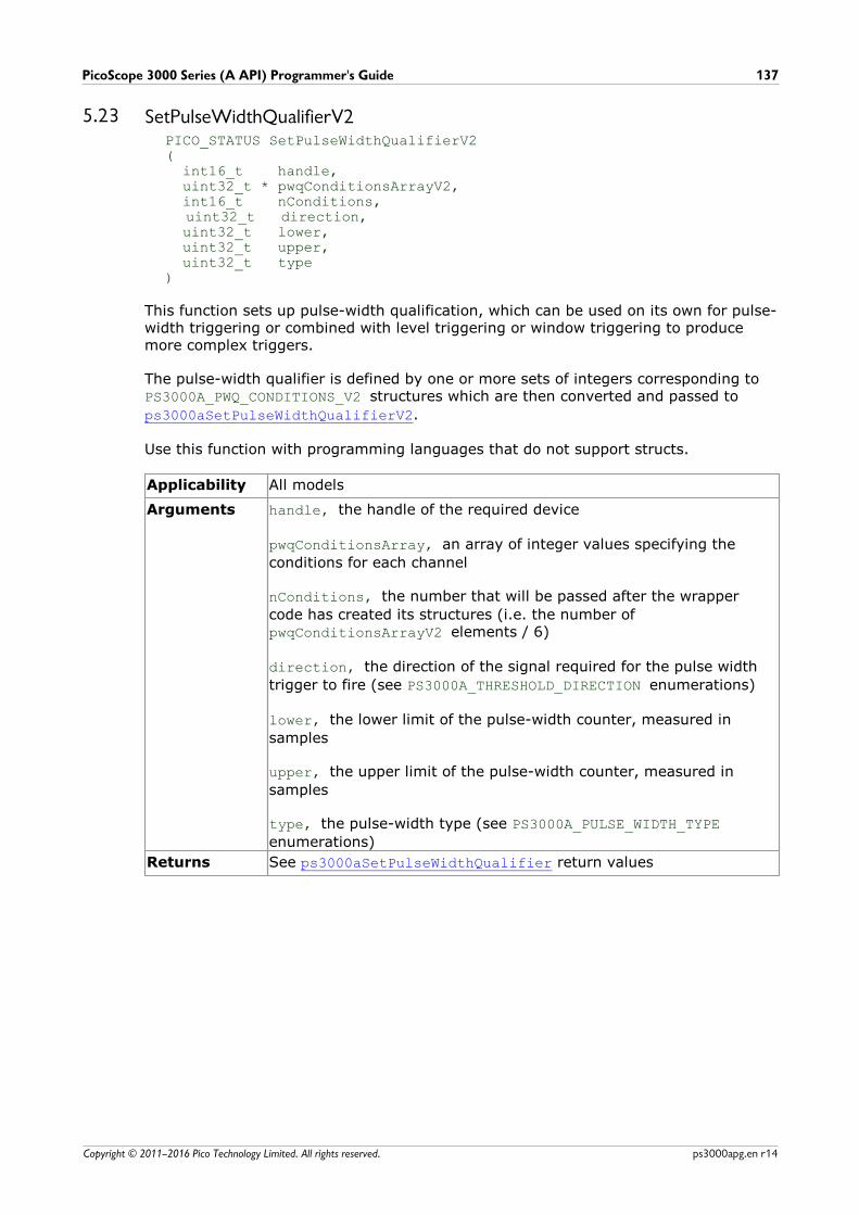
PicoScope 3000 Series (A API) Programmer's Guide 137
Copyright © 2011–2016 Pico Technology Limited. All rights reserved. ps3000apg.en r14
5.23 SetPulseWidthQualifierV2PICO_STATUS SetPulseWidthQualifierV2( int16_t handle, uint32_t * pwqConditionsArrayV2, int16_t nConditions,
uint32_t direction, uint32_t lower, uint32_t upper, uint32_t type)
This function sets up pulse-width qualification, which can be used on its own for pulse-width triggering or combined with level triggering or window triggering to producemore complex triggers.
The pulse-width qualifier is defined by one or more sets of integers corresponding to PS3000A_PWQ_CONDITIONS_V2 structures which are then converted and passed to
ps3000aSetPulseWidthQualifierV2.
Use this function with programming languages that do not support structs.
Applicability All models
Arguments handle, the handle of the required device
pwqConditionsArray, an array of integer values specifying the
conditions for each channel
nConditions, the number that will be passed after the wrapper
code has created its structures (i.e. the number of pwqConditionsArrayV2 elements / 6)
direction, the direction of the signal required for the pulse width
trigger to fire (see PS3000A_THRESHOLD_DIRECTION enumerations)
lower, the lower limit of the pulse-width counter, measured in
samples
upper, the upper limit of the pulse-width counter, measured in
samples
type, the pulse-width type (see PS3000A_PULSE_WIDTH_TYPE
enumerations)
Returns See ps3000aSetPulseWidthQualifier return values

Wrapper functions138
Copyright © 2011–2016 Pico Technology Limited. All rights reserved.ps3000apg.en r14
5.24 SetTriggerConditionsPICO_STATUS SetTriggerConditions( int16_t handle, int32_t * conditionsArray, int16_t nConditions)
This function sets up trigger conditions on the scope's inputs. The trigger is defined byone or more sets of integers corresponding to PS3000A_TRIGGER_CONDITIONS
structures which are then converted and passed to ps3000aSetTriggerChannelConditions.
Use this function with programming languages that do not support structs.
Applicability Analog-input models only ( for MSOs use SetTriggerConditionsV2)
Arguments handle, the handle of the required device
conditionsArray, an array of integer values specifying the
conditions for each channel
nConditions, the number that will be passed after the wrapper
code has created its structures (i.e. the number of conditionsArray
elements divided by 7)
Returns See ps3000aSetTriggerChannelConditions return values
Examples
Below are examples for using the function in Visual Basic.
To trigger off channels A OR B
Dim conditionsArray(13) As IntegerconditionsArray(0) = 1 ' channel AconditionsArray(1) = 0 ' channel BconditionsArray(2) = 0 ' channel CconditionsArray(3) = 0 ' channel DconditionsArray(4) = 0 ' externalconditionsArray(5) = 0 ' auxconditionsArray(6) = 0 ' pulse width qualifier
' *** OR'ed with
conditionsArray(7) = 0 ' channel AconditionsArray(8) = 1 ' channel BconditionsArray(9) = 0 ' channel CconditionsArray(10) = 0 ' channel DconditionsArray(11) = 0 ' externalconditionsArray(12) = 0 ' auxconditionsArray(13) = 0 ' pulse width qualifierstatus = SetTriggerConditions(handle, conditionsArray(0), 2)
To trigger off channels A AND B
Dim conditionsArray(6) As IntegerconditionsArray(0) = 1 ' channel AconditionsArray(1) = 1 ' channel BconditionsArray(2) = 0 ' channel CconditionsArray(3) = 0 ' channel DconditionsArray(4) = 0 ' externalconditionsArray(5) = 0 ' auxconditionsArray(6) = 0 ' pulse width qualifier
status = SetTriggerConditions(handle, conditionsArray(0), 1)

PicoScope 3000 Series (A API) Programmer's Guide 139
Copyright © 2011–2016 Pico Technology Limited. All rights reserved. ps3000apg.en r14
5.25 SetTriggerConditionsV2PICO_STATUS SetTriggerConditionsV2( int16_t handle, int32_t * conditionsArrayV2, int16_t nConditions)
This function sets up trigger conditions on the scope's inputs. The trigger is defined byone or more sets of integers corresponding to PS3000A_TRIGGER_CONDITIONS_V2
structures which are then converted and passed to ps3000aSetTriggerChannelConditionsV2.
Use this function with programming languages that do not support structs.
Applicability All models
Arguments handle, the handle of the required device
conditionsArrayV2, an array of integer values specifying the
conditions for each channel
nConditions, the number that will be passed after the wrapper
code has created its structures (i.e. the number of conditionsArray
elements divided by 8)
Returns See ps3000aSetTriggerChannelConditionsV2 return values
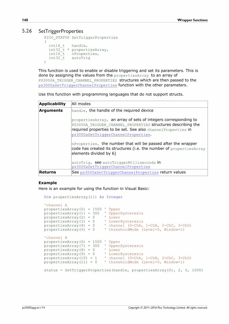
Wrapper functions140
Copyright © 2011–2016 Pico Technology Limited. All rights reserved.ps3000apg.en r14
5.26 SetTriggerPropertiesPICO_STATUS SetTriggerProperties( int16_t handle, int32_t * propertiesArray, int16_t nProperties, int32_t autoTrig)
This function is used to enable or disable triggering and set its parameters. This isdone by assigning the values from the propertiesArray to an array of
PS3000A_TRIGGER_CHANNEL_PROPERTIES structures which are then passed to the
ps3000aSetTriggerChannelProperties function with the other parameters.
Use this function with programming languages that do not support structs.
Applicability All modes
Arguments handle, the handle of the required device
propertiesArray, an array of sets of integers corresponding to
PS3000A_TRIGGER_CHANNEL_PROPERTIES structures describing the
required properties to be set. See also channelProperties in
ps3000aSetTriggerChannelProperties.
nProperties, the number that will be passed after the wrapper
code has created its structures (i.e. the number of propertiesArray
elements divided by 6)
autoTrig, see autoTriggerMilliseconds inps3000aSetTriggerChannelProperties
Returns See ps3000aSetTriggerChannelProperties return values
Example
Here is an example for using the function in Visual Basic:
Dim propertiesArray(11) As Integer
'channel ApropertiesArray(0) = 1500 ' Upper propertiesArray(1) = 300 ' UpperHysteresispropertiesArray(2) = 0 ' LowerpropertiesArray(3) = 0 ' LowerHysteresispropertiesArray(4) = 0 ' channel (0=ChA, 1=ChB, 2=ChC, 3=ChD)propertiesArray(5) = 0 ' thresholdMode (Level=0, Window=1)
'channel BpropertiesArray(6) = 1500 ' Upper propertiesArray(7) = 300 ' UpperHysteresispropertiesArray(8) = 0 ' LowerpropertiesArray(9) = 0 ' LowerHysteresispropertiesArray(10) = 1 ' channel (0=ChA, 1=ChB, 2=ChC, 3=ChD)propertiesArray(11) = 0 ' thresholdMode (Level=0, Window=1)
status = SetTriggerProperties(handle, propertiesArray(0), 2, 0, 1000)
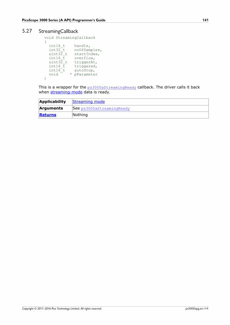
PicoScope 3000 Series (A API) Programmer's Guide 141
Copyright © 2011–2016 Pico Technology Limited. All rights reserved. ps3000apg.en r14
5.27 StreamingCallbackvoid StreamingCallback( int16_t handle, int32_t noOfSamples, uint32_t startIndex, int16_t overflow, uint32_t triggerAt, int16_t triggered, int16_t autoStop, void * pParameter)
This is a wrapper for the ps3000aStreamingReady callback. The driver calls it back
when streaming-mode data is ready.
Applicability Streaming mode
Arguments See ps3000aStreamingReady
Returns Nothing

Programming examples142
Copyright © 2011–2016 Pico Technology Limited. All rights reserved.ps3000apg.en r14
6 Programming examplesYour PicoScope SDK installation includes example code in a number of programminglanguages and development environments. Please refer to the SDK for details.
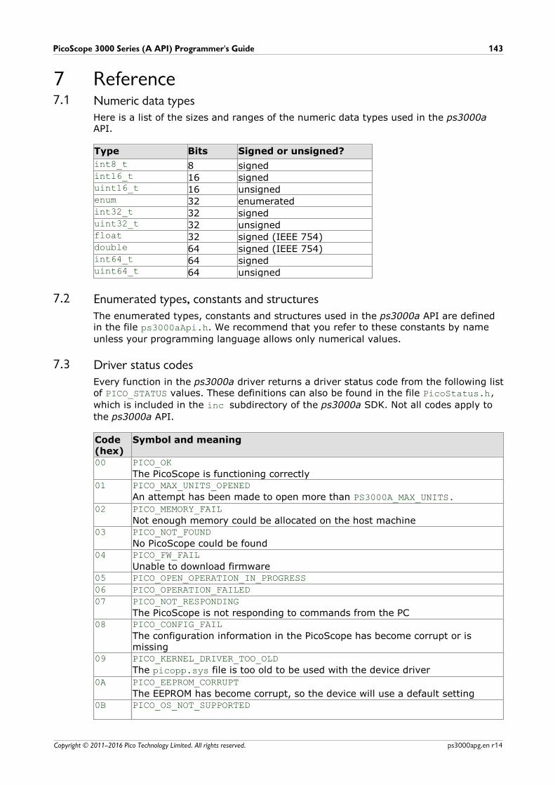
PicoScope 3000 Series (A API) Programmer's Guide 143
Copyright © 2011–2016 Pico Technology Limited. All rights reserved. ps3000apg.en r14
7 Reference7.1 Numeric data types
Here is a list of the sizes and ranges of the numeric data types used in the ps3000aAPI.
Type Bits Signed or unsigned?
int8_t 8 signedint16_t 16 signeduint16_t 16 unsignedenum 32 enumeratedint32_t 32 signeduint32_t 32 unsignedfloat 32 signed (IEEE 754)double 64 signed (IEEE 754)int64_t 64 signeduint64_t 64 unsigned
7.2 Enumerated types, constants and structuresThe enumerated types, constants and structures used in the ps3000a API are definedin the file ps3000aApi.h. We recommend that you refer to these constants by name
unless your programming language allows only numerical values.
7.3 Driver status codesEvery function in the ps3000a driver returns a driver status code from the following listof PICO_STATUS values. These definitions can also be found in the file PicoStatus.h,
which is included in the inc subdirectory of the ps3000a SDK. Not all codes apply to
the ps3000a API.
Code(hex)
Symbol and meaning
00 PICO_OK
The PicoScope is functioning correctly01 PICO_MAX_UNITS_OPENED
An attempt has been made to open more than PS3000A_MAX_UNITS.
02 PICO_MEMORY_FAIL
Not enough memory could be allocated on the host machine03 PICO_NOT_FOUND
No PicoScope could be found04 PICO_FW_FAIL
Unable to download firmware05 PICO_OPEN_OPERATION_IN_PROGRESS
06 PICO_OPERATION_FAILED
07 PICO_NOT_RESPONDING
The PicoScope is not responding to commands from the PC08 PICO_CONFIG_FAIL
The configuration information in the PicoScope has become corrupt or ismissing
09 PICO_KERNEL_DRIVER_TOO_OLD
The picopp.sys file is too old to be used with the device driver
0A PICO_EEPROM_CORRUPT
The EEPROM has become corrupt, so the device will use a default setting0B PICO_OS_NOT_SUPPORTED

Reference144
Copyright © 2011–2016 Pico Technology Limited. All rights reserved.ps3000apg.en r14
The operating system on the PC is not supported by this driver0C PICO_INVALID_HANDLE
There is no device with the handle value passed0D PICO_INVALID_PARAMETER
A parameter value is not valid0E PICO_INVALID_TIMEBASE
The timebase is not supported or is invalid0F PICO_INVALID_VOLTAGE_RANGE
The voltage range is not supported or is invalid10 PICO_INVALID_CHANNEL
The channel number is not valid on this device or no channels have been set11 PICO_INVALID_TRIGGER_CHANNEL
The channel set for a trigger is not available on this device12 PICO_INVALID_CONDITION_CHANNEL
The channel set for a condition is not available on this device13 PICO_NO_SIGNAL_GENERATOR
The device does not have a signal generator14 PICO_STREAMING_FAILED
Streaming has failed to start or has stopped without user request15 PICO_BLOCK_MODE_FAILED
Block failed to start - a parameter may have been set wrongly16 PICO_NULL_PARAMETER
A parameter that was required is NULL
18 PICO_DATA_NOT_AVAILABLE
No data is available from a run block call19 PICO_STRING_BUFFER_TOO_SMALL
The buffer passed for the information was too small1A PICO_ETS_NOT_SUPPORTED
ETS is not supported on this device1B PICO_AUTO_TRIGGER_TIME_TOO_SHORT
The auto trigger time is less than the time it will take to collect the pre-triggerdata
1C PICO_BUFFER_STALL
The collection of data has stalled as unread data would be overwritten1D PICO_TOO_MANY_SAMPLES
Number of samples requested is more than available in the current memorysegment
1E PICO_TOO_MANY_SEGMENTS
Not possible to create number of segments requested1F PICO_PULSE_WIDTH_QUALIFIER
A null pointer has been passed in the trigger function or one of theparameters is out of range
20 PICO_DELAY
One or more of the hold-off parameters are out of range21 PICO_SOURCE_DETAILS
One or more of the source details are incorrect22 PICO_CONDITIONS
One or more of the conditions are incorrect23 PICO_USER_CALLBACK
The driver's thread is currently in the ps3000a...Ready callback function andtherefore the action cannot be carried out
24 PICO_DEVICE_SAMPLING
An attempt is being made to get stored data while streaming. Either stopstreaming by calling ps3000aStop, or use ps3000aGetStreamingLatestValues
25 PICO_NO_SAMPLES_AVAILABLE
...because a run has not been completed
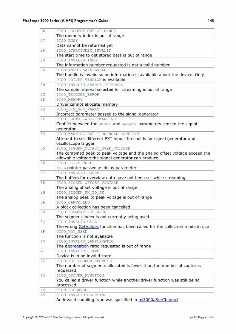
PicoScope 3000 Series (A API) Programmer's Guide 145
Copyright © 2011–2016 Pico Technology Limited. All rights reserved. ps3000apg.en r14
26 PICO_SEGMENT_OUT_OF_RANGE
The memory index is out of range27 PICO_BUSY
Data cannot be returned yet28 PICO_STARTINDEX_INVALID
The start time to get stored data is out of range29 PICO_INVALID_INFO
The information number requested is not a valid number2A PICO_INFO_UNAVAILABLE
The handle is invalid so no information is available about the device. Only PICO_DRIVER_VERSION is available.
2B PICO_INVALID_SAMPLE_INTERVAL
The sample interval selected for streaming is out of range2C PICO_TRIGGER_ERROR
2D PICO_MEMORY
Driver cannot allocate memory2E PICO_SIG_GEN_PARAM
Incorrect parameter passed to the signal generator2F PICO_SHOTS_SWEEPS_WARNING
Conflict between the shots and sweeps parameters sent to the signal
generator33 PICO_WARNING_EXT_THRESHOLD_CONFLICT
Attempt to set different EXT input thresholds for signal generator andoscilloscope trigger
35 PICO_SIGGEN_OUTPUT_OVER_VOLTAGE
The combined peak to peak voltage and the analog offset voltage exceed theallowable voltage the signal generator can produce
36 PICO_DELAY_NULL
NULL pointer passed as delay parameter
37 PICO_INVALID_BUFFER
The buffers for overview data have not been set while streaming38 PICO_SIGGEN_OFFSET_VOLTAGE
The analog offset voltage is out of range39 PICO_SIGGEN_PK_TO_PK
The analog peak to peak voltage is out of range3A PICO_CANCELLED
A block collection has been cancelled3B PICO_SEGMENT_NOT_USED
The segment index is not currently being used3C PICO_INVALID_CALL
The wrong GetValues function has been called for the collection mode in use3F PICO_NOT_USED
The function is not available40 PICO_INVALID_SAMPLERATIO
The aggregation ratio requested is out of range41 PICO_INVALID_STATE
Device is in an invalid state42 PICO_NOT_ENOUGH_SEGMENTS
The number of segments allocated is fewer than the number of capturesrequested
43 PICO_DRIVER_FUNCTION
You called a driver function while another driver function was still beingprocessed
44 PICO_RESERVED
45 PICO_INVALID_COUPLING
An invalid coupling type was specified in ps3000aSetChannel
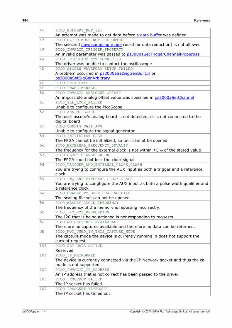
Reference146
Copyright © 2011–2016 Pico Technology Limited. All rights reserved.ps3000apg.en r14
46 PICO_BUFFERS_NOT_SET
An attempt was made to get data before a data buffer was defined47 PICO_RATIO_MODE_NOT_SUPPORTED
The selected downsampling mode (used for data reduction) is not allowed49 PICO_INVALID_TRIGGER_PROPERTY
An invalid parameter was passed to ps3000aSetTriggerChannelProperties4A PICO_INTERFACE_NOT_CONNECTED
The driver was unable to contact the oscilloscope4D PICO_SIGGEN_WAVEFORM_SETUP_FAILED
A problem occurred in ps3000aSetSigGenBuiltIn orps3000aSetSigGenArbitrary
4E PICO_FPGA_FAIL
4F PICO_POWER_MANAGER
50 PICO_INVALID_ANALOGUE_OFFSET
An impossible analog offset value was specified in ps3000aSetChannel51 PICO_PLL_LOCK_FAILED
Unable to configure the PicoScope52 PICO_ANALOG_BOARD
The oscilloscope's analog board is not detected, or is not connected to thedigital board
53 PICO_CONFIG_FAIL_AWG
Unable to configure the signal generator54 PICO_INITIALISE_FPGA
The FPGA cannot be initialized, so unit cannot be opened56 PICO_EXTERNAL_FREQUENCY_INVALID
The frequency for the external clock is not within ±5% of the stated value57 PICO_CLOCK_CHANGE_ERROR
The FPGA could not lock the clock signal58 PICO_TRIGGER_AND_EXTERNAL_CLOCK_CLASH
You are trying to configure the AUX input as both a trigger and a referenceclock
59 PICO_PWQ_AND_EXTERNAL_CLOCK_CLASH
You are trying to congfigure the AUX input as both a pulse width qualifier anda reference clock
5A PICO_UNABLE_TO_OPEN_SCALING_FILE
The scaling file set can not be opened.5B PICO_MEMORY_CLOCK_FREQUENCY
The frequency of the memory is reporting incorrectly.5C PICO_I2C_NOT_RESPONDING
The I2C that is being actioned is not responding to requests.5D PICO_NO_CAPTURES_AVAILABLE
There are no captures available and therefore no data can be returned.5E PICO_NOT_USED_IN_THIS_CAPTURE_MODE
The capture mode the device is currently running in does not support thecurrent request.
103 PICO_GET_DATA_ACTIVE
Reserved104 PICO_IP_NETWORKED
The device is currently connected via the IP Network socket and thus the callmade is not supported.
105 PICO_INVALID_IP_ADDRESS
An IP address that is not correct has been passed to the driver.106 PICO_IPSOCKET_FAILED
The IP socket has failed.107 PICO_IPSOCKET_TIMEDOUT
The IP socket has timed out.

PicoScope 3000 Series (A API) Programmer's Guide 147
Copyright © 2011–2016 Pico Technology Limited. All rights reserved. ps3000apg.en r14
108 PICO_SETTINGS_FAILED
The settings requested have failed to be set.109 PICO_NETWORK_FAILED
The network connection has failed.10A PICO_WS2_32_DLL_NOT_LOADED
Unable to load the WS2 dll.10B PICO_INVALID_IP_PORT
The IP port is invalid10C PICO_COUPLING_NOT_SUPPORTED
The type of coupling requested is not supported on the opened device.10D PICO_BANDWIDTH_NOT_SUPPORTED
Bandwidth limit is not supported on the opened device.10E PICO_INVALID_BANDWIDTH
The value requested for the bandwidth limit is out of range.10F PICO_AWG_NOT_SUPPORTED
The arbitrary waveform generator is not supported by the opened device.110 PICO_ETS_NOT_RUNNING
Data has been requested with ETS mode set but run block has not beencalled, or stop has been called.
111 PICO_SIG_GEN_WHITENOISE_NOT_SUPPORTED
White noise is not supported on the opened device.112 PICO_SIG_GEN_WAVETYPE_NOT_SUPPORTED
The wave type requested is not supported by the opened device. 113 PICO_INVALID_DIGITAL_PORT
A port number that does not evaluate to either PS3000A_DIGITAL_PORT0 or
PS3000A_DIGITAL_PORT1, the ports that are supported.
114 PICO_INVALID_DIGITAL_CHANNEL
The digital channel is not in the range PS3000A_DIGITAL_CHANNEL0 to
PS3000_DIGITAL_CHANNEL15, the digital channels that are supported.
115 PICO_INVALID_DIGITAL_TRIGGER_DIRECTION
The digital trigger direction is not a valid trigger direction and should be equalin value to one of the PS3000A_DIGITAL_DIRECTION enumerations.
116 PICO_SIG_GEN_PRBS_NOT_SUPPORTED
Siggen does not generate pseudo-random bit stream.117 PICO_ETS_NOT_AVAILABLE_WITH_LOGIC_CHANNELS
When a digital port is enabled, ETS sample mode is not available for use.118 PICO_WARNING_REPEAT_VALUE
Not applicable to this device.119 PICO_POWER_SUPPLY_CONNECTED
4-Channel only - The DC power supply is connected.11A PICO_POWER_SUPPLY_NOT_CONNECTED
4-Channel only - The DC power supply isn’t connected.11B PICO_POWER_SUPPLY_REQUEST_INVALID
Incorrect power mode passed for current power source.11C PICO_POWER_SUPPLY_UNDERVOLTAGE
The supply voltage from the USB source is too low.11D PICO_CAPTURING_DATA
The oscilloscope is in the process of capturing data.11E PICO_USB3_0_DEVICE_NON_USB3_0_PORT
A USB 3.0 device is connected to a non-USB 3.0 port.
Reference148
Copyright © 2011–2016 Pico Technology Limited. All rights reserved.ps3000apg.en r14
7.4 GlossaryAggregation. The ps3000a driver can use a method called aggregation to reduce theamount of data your application needs to process. This means that for every block ofconsecutive samples, it stores only the minimum and maximum values. You can setthe number of samples in each block, called the aggregation parameter, when you call ps3000aRunStreaming for real-time capture, and when you call
ps3000aGetStreamingLatestValues to obtain post-processed data.
Aliasing. An effect that can cause digital oscilloscopes to display fast-movingwaveforms incorrectly, by showing spurious low-frequency signals ("aliases") that donot exist in the input. To avoid this problem, choose a sampling rate that is at leasttwice the frequency of the fastest-changing input signal.
Analog bandwidth. All oscilloscopes have an upper limit to the range of frequenciesat which they can measure accurately. The analog bandwidth of an oscilloscope isdefined as the frequency at which a measured sine wave has half the power (or about71% of the amplitude) of the input sine wave.
AWG. Arbitrary waveform generator. On selected models, the signal generator outputmarked Gen or AWG can produce an arbitrary waveform defined by the user. Definethis waveform by calling ps3000aSetSigGenArbitrary and related functions.
Block mode. A sampling mode in which the computer prompts the oscilloscope tocollect a block of data into its internal memory before stopping the oscilloscope andtransferring the whole block into computer memory. This mode of operation iseffective when the input signal being sampled is high frequency. Note: To avoid aliasing effects, the maximum input frequency must be less than half the samplingrate.
Buffer size. The size, in samples, of the oscilloscope buffer memory. The buffermemory is used by the oscilloscope to temporarily store data before transferring it tothe PC.
ETS. Equivalent Time Sampling. ETS constructs a representation of a repetitive signalby accumulating information over many similar cycles. This allows the oscilloscope tocapture fast-repeating signals that have a higher frequency than the maximumsampling rate. Note: ETS cannot be used for one-shot or non-repetitive signals.
External trigger. This is the BNC socket marked Ext. It can be used as a signal tostart data capture, but not as an analog input.
Flexible power. The 4-channel 3000 Series oscilloscopes can be powered by eitherthe USB port or the power supply supplied. A two-headed USB cable, availableseparately, can be used to obtain power from two USB ports.
Maximum sampling rate. The maximum number of samples the oscilloscope iscapable of acquiring per second. Maximum sample rates are given in MS/s(megasamples per second). The higher the sampling capability of the oscilloscope, themore accurate the representation of the high frequencies in a fast signal.
MSO (Mixed signal oscilloscope). An oscilloscope that has both analog and digitalinputs.
Overvoltage. Any input voltage to the oscilloscope must not exceed the overvoltagelimit, measured with respect to ground, otherwise the oscilloscope may bepermanently damaged.
PicoScope 3000 Series (A API) Programmer's Guide 149
Copyright © 2011–2016 Pico Technology Limited. All rights reserved. ps3000apg.en r14
Signal generator. This is a feature of some oscilloscopes which allows a signal to begenerated without an external input device being present. The signal generator outputis the BNC socket marked Gen on the oscilloscope. If you connect a BNC cablebetween this and one of the channel inputs, you can send a signal into one of thechannels. It can generate a sine, square or triangle wave that can be swept back andforth.
Streaming mode. A sampling mode in which the oscilloscope samples data andreturns it to the computer in an unbroken stream. This mode of operation is effectivewhen the input signal being sampled contains only low frequencies.
USB 1.1. USB (Universal Serial Bus) is a standard port that enables you to connectexternal devices to PCs. A USB 1.1 port supports data transfer rates up to 12 megabitsper second, much faster than an RS-232 port.
USB 2.0. A USB 2.0 port supports data transfer rates up to 480 Mbps and isbackward-compatible with USB 1.1.
USB 3.0. A USB 3.0 port supports data transfer rates up to 5 Gbps and is backward-compatible with USB 2.0 and USB 1.1.
Vertical resolution. A value, in bits, indicating the degree of precision with which theoscilloscope can turn input voltages into digital values.
Voltage range. The voltage range is the difference between the maximum andminimum voltages that can be accurately measured by the oscilloscope.

PicoScope 3000 Series (A API) Programmer's Guide 151
Copyright © 2011–2016 Pico Technology Limited. All rights reserved. ps3000apg.en r14
Index
AAC adaptor 4
AC/DC coupling 72
Access 2
ADC count 59, 61
Aggregation 21
Analog offset 33, 72
Arbitrary waveform generator 87, 89
AWG
buffer lengths 109
sample values 109
BBandwidth limiter 72
Block mode 7, 9, 10, 11
asynchronous call 12
callback 26
polling status 57
running 67
CCallback function 9, 19
block mode 26
for data 30
streaming mode 113
Channels
enabling 72
settings 72
Closing units 28
Communication 66
Connection 66
Constants 143
Copyright 2
Coupling type, setting 72
DData acquisition 21
Data buffers
declaring 73
declaring, aggregation mode 74
Data retention 4, 10
deltaPhase argument (AWG) 89
Digital connector 7
Digital data 6
Digital port 6
Downsampling 10, 47
maximum ratio 35, 36
modes 48
Driver 3
EEnabling channels 72
Enumerated types 143
Enumerating oscilloscopes 31
ETS 9
overview 19
setting time buffers 77, 78
setting up 76
using 20
FFitness for purpose 2
Functions
list of 24
ps3000aBlockReady 26
ps3000aChangePowerSource 27
ps3000aCloseUnit 28
ps3000aCurrentPowerSource 29
ps3000aDataReady 30
ps3000aEnumerateUnits 31
ps3000aFlashLed 32
ps3000aGetAnalogueOffset 33
ps3000aGetChannelInformation 34
ps3000aGetMaxDownSampleRatio 35
ps3000aGetMaxEtsValues 36
ps3000aGetMaxSegments 37
ps3000aGetNoOfCaptures 38, 39
ps3000aGetStreamingLatestValues 40
ps3000aGetTimebase 8, 41
ps3000aGetTimebase2 42
ps3000aGetTriggerInfoBulk 43
ps3000aGetTriggerTimeOffset 44
ps3000aGetTriggerTimeOffset64 45
ps3000aGetUnitInfo 46
ps3000aGetValues 12, 47
ps3000aGetValuesAsync 12, 49
ps3000aGetValuesBulk 50
ps3000aGetValuesOverlapped 51
ps3000aGetValuesOverlappedBulk 52
ps3000aGetValuesTriggerTimeOffsetBulk 54
ps3000aGetValuesTriggerTimeOffsetBulk64 55
ps3000aHoldOff 56
ps3000aIsReady 57
ps3000aIsTriggerOrPulseWidthQualifierEnabled 58
Index152
Copyright © 2011–2016 Pico Technology Limited. All rights reserved.ps3000apg.en r14
Functions
ps3000aMaximumValue 5, 59
ps3000aMemorySegments 60
ps3000aMinimumValue 5, 61
ps3000aNoOfStreamingValues 62
ps3000aOpenUnit 63
ps3000aOpenUnitAsync 64
ps3000aOpenUnitProgress 65
ps3000aPingUnit 66
ps3000aRunBlock 67
ps3000aRunStreaming 69
ps3000aSetChannel 5, 72
ps3000aSetDataBuffer 73
ps3000aSetDataBuffers 74
ps3000aSetDigitalPort 75
ps3000aSetEts 19, 76
ps3000aSetEtsTimeBuffer 77
ps3000aSetEtsTimeBuffers 78
ps3000aSetNoOfCaptures 79
ps3000aSetPulseWidthDigitalPortProperties 80
ps3000aSetPulseWidthQualifier 81
ps3000aSetPulseWidthQualifierV2 84
ps3000aSetSigGenArbitrary 87
ps3000aSetSigGenBuiltIn 91
ps3000aSetSigGenBuiltInV2 94
ps3000aSetSigGenPropertiesArbitrary 95
ps3000aSetSigGenPropertiesBuiltIn 96
ps3000aSetSimpleTrigger 7, 97
ps3000aSetTriggerChannelConditions 7, 98
ps3000aSetTriggerChannelConditionsV2 100
ps3000aSetTriggerChannelDirections 7, 102
ps3000aSetTriggerChannelProperties 7, 103
ps3000aSetTriggerDelay 106
ps3000aSetTriggerDigitalPortProperties 107
ps3000aSigGenArbitraryMinMaxValues 109
ps3000aSigGenFrequencyToPhase 110
ps3000aSigGenSoftwareControl 111
ps3000aStop 12, 112
ps3000aStreamingReady 113
GGrant of license 2
HHysteresis 104, 108
IIndex modes 89
Information, reading from units 46
Input range, selecting 72
Intended use 1
LLED
flashing 32
Legal information 2
Liability 2
MMemory in scope 10
Memory segments 10, 11, 21, 60
Mission-critical applications 2
Multi-unit operation 23
NNumeric data types 143
OOne-shot signals 19
Opening a unit 63
checking progress 65
without blocking 64
PPC oscilloscope 1
PC requirements 3
PICO_STATUS enum type 143
PicoScope 3000 MSO Series 1
PicoScope 3000A Series 1
PicoScope 3000B Series 1
PicoScope 3000D MSO Series 1
PicoScope 3000D Series 1
PicoScope software 1, 3, 143
Ports
enabling 75
PORT0, PORT1 6
settings 75
Power source 4, 27, 29
ps3000a API 3
ps3000a.dll 3
PS3000A_CONDITION_ constants 83
PS3000A_CONDITION_V2 constants 86
PS3000A_LEVEL constant 104, 108
PS3000A_PWQ_CONDITIONS structure 83
PS3000A_PWQ_CONDITIONS_V2 structure 86
PS3000A_RATIO_MODE_AGGREGATE 48
PS3000A_RATIO_MODE_AVERAGE 48
PicoScope 3000 Series (A API) Programmer's Guide 153
Copyright © 2011–2016 Pico Technology Limited. All rights reserved. ps3000apg.en r14
PS3000A_RATIO_MODE_DECIMATE 48
PS3000A_TIME_UNITS constant 44, 45
PS3000A_TRIGGER_CHANNEL_PROPERTIESstructure 104, 108
PS3000A_TRIGGER_CONDITION constants 99
PS3000A_TRIGGER_CONDITION_V2 constants 101
PS3000A_TRIGGER_CONDITIONS 98
PS3000A_TRIGGER_CONDITIONS structure 99
PS3000A_TRIGGER_CONDITIONS_V2 100
PS3000A_TRIGGER_CONDITIONS_V2 structure 101
PS3000A_WINDOW constant 104, 108
Pulse-width qualifier 81
conditions 83
requesting status 58
Pulse-width qualifierV2 84
conditions 86
RRanges 34
Rapid block mode 9, 13, 13, 38, 39
aggregation 17
no aggregation 15
setting number of captures 79
Retrieving data 47, 49
block mode, deferred 51
rapid block mode 50
rapid block mode, deferred 52
stored 23
streaming mode 40
Retrieving times
rapid block mode 54, 55
SSampling rate
block mode 10
streaming mode 9
Scaling 5
Serial numbers 31
Setup time 10
Signal generator
arbitrary waveforms 87
built-in waveforms 91, 94
calculating phase 110
software trigger 111
Spectrum analyzer 1
Status codes 143
Stopping sampling 112
Streaming mode 9, 21
callback 113
getting number of samples 62
retrieving data 40
running 69
using 22
Structures 143
Support 2
TThreshold voltage 7
Time buffers
setting for ETS 77, 78
Timebase 8
calculating 41, 42
Trademarks 2
Trigger 7
channel properties 80, 103, 107
conditions 98, 99, 100, 101
delay 106
digital port pulse width 80
digital ports 107
directions 102
external 5
pulse-width qualifier 81
pulse-width qualifier conditions 83
pulse-width qualifierV2 84
pulse-width qualifierV2 conditions 86
requesting status 58
setting up 97
stability 19
time offset 44, 45
time offsets in rapid mode 43
UUpgrades 2
Usage 2
USB 1, 3, 3
hub 23
powering 4
VViruses 2
Voltage range 5
selecting 72
WWinUsb.sys 3
Wrapper functions
AutoStopped 116
AvailableData 117
Index154
Copyright © 2011–2016 Pico Technology Limited. All rights reserved.ps3000apg.en r14
Wrapper functions
ClearTriggerReady 119
decrementDeviceCount 120
GetStreamingLatestValues 122
IsReady 124
IsTriggerReady 125
resetNextDeviceIndex 126
RunBlock 127
setAppAndDriverBuffers 128
setAppAndDriverDigiBuffers 130
setChannelCount 132
setDigitalPortCount 133
setEnabledChannels 134
setEnabledDigitalPorts 135
setMaxMinAppAndDriverBuffers 129
setMaxMinAppAndDriverDigiBuffers 131
SetPulseWidthQualifier 136
SetPulseWidthQualifierV2 137
SetTriggerConditions 138
SetTriggerConditionsV2 139
SetTriggerProperties 140
StreamingCallback 141
using 114

UK headquarters
Pico TechnologyJames HouseColmworth Business ParkSt. NeotsCambridgeshirePE19 8YPUnited Kingdom
Tel: +44 (0) 1480 396 395Fax: +44 (0) 1480 396 296
[email protected]@picotech.com
www.picotech.com
Copyright © 2011–2016 Pico Technology Limited. All rights reserved.
ps3000apg.en r14 2016-09-21
US headquarters
Pico Technology320 N Glenwood BlvdTylerTexas 75702United States of America
Tel: +1 800 591 2796Fax: +1 620 272 0981