Physics 364 Arduino Lab 1 Vithayathil/Krollpositron.hep.upenn.edu/wja/p364/2014/files/lab20.pdf ·...
14
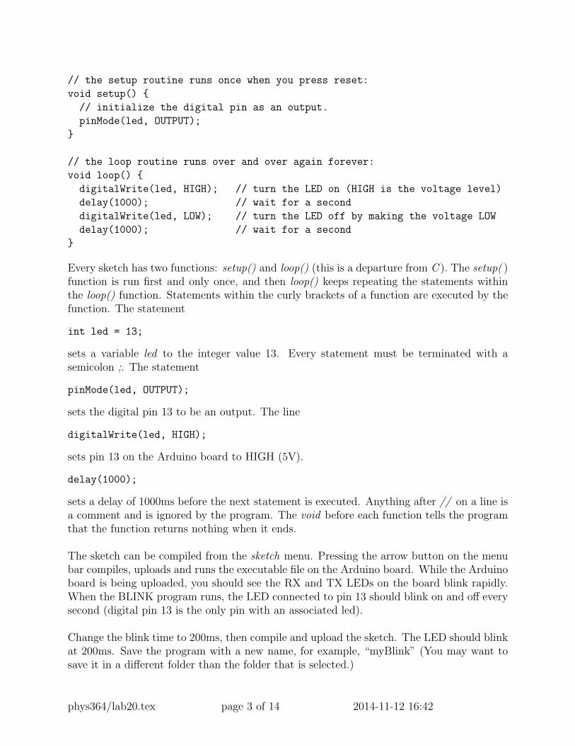
Physics 364 Arduino Lab 1 Vithayathil/Kroll Adapted from a lab originally written by Simon Hastings and Bill Ashmanskas Last revised: 2014-11-12 Introduction This lab introduces you to an electronic development platform, called Arduino, that has a large user/developer base. This platform can be used to learn about and use various elec- tronic modules such as LCD modules, stepper motors, communications and network tech- nology etc. The goal in the next 2 or 3 labs is to learn how to write programs or “sketches” to use the Arduino board to build a counter like you built with flipflops in a previous lab and to build a basic digital-to-analog converter and a basic analog-to-digital converter. The specific platform we will use is the Arduino UNO Rev3 board, which can be connected to your laptop via a USB cable. The Arduino UNO is depicted in Fig. 1. Figure 1: The revision 3 surface-mount-design Arduino Uno board. The top of the board is shown on the left-hand photograph, and the bottom of the board is shown on the right-hand photograph. The Arduino UNO contains a microcontroller—a simple computer—based on the Atmel Cor- poration ATmega328 chip. It is possible to read and write digital data (HIGH/LOW) to digital pins 1-13 (these pins are shown in the photograph on the left-hand side of Fig. 1), to read analog signals with 10-bit resolution on analog pins A0-A5, and to write pseudo analog data (by varying the pulse duty cycle) on the digital pins labelled with a “˜” symbol on them: 3, 5, 6, 9, 10, and 12. The board receives power via the USB cable, and programs written in “C’ language are downloaded via the USB cable to the Arduino board to run your device. For the circuits you will build using the Arduino, no external DC power supply is required. You can get 5V directly from the 5V power pin on the Arduino. For your ground reference, you may use any of the three ground pins on the Arduino. phys364/lab20.tex page 1 of 14 2014-11-12 16:42
Transcript of Physics 364 Arduino Lab 1 Vithayathil/Krollpositron.hep.upenn.edu/wja/p364/2014/files/lab20.pdf ·...

Physics 364 Arduino Lab 1 Vithayathil/KrollAdapted from a lab originally written by Simon Hastings and Bill Ashmanskas
Last revised: 2014-11-12
Introduction
This lab introduces you to an electronic development platform, called Arduino, that has alarge user/developer base. This platform can be used to learn about and use various elec-tronic modules such as LCD modules, stepper motors, communications and network tech-nology etc. The goal in the next 2 or 3 labs is to learn how to write programs or “sketches”to use the Arduino board to build a counter like you built with flipflops in a previous laband to build a basic digital-to-analog converter and a basic analog-to-digital converter.
The specific platform we will use is the Arduino UNO Rev3 board, which can be connectedto your laptop via a USB cable. The Arduino UNO is depicted in Fig. 1.
Figure 1: The revision 3 surface-mount-design Arduino Uno board. The top of the board isshown on the left-hand photograph, and the bottom of the board is shown on the right-handphotograph.
The Arduino UNO contains a microcontroller—a simple computer—based on the Atmel Cor-poration ATmega328 chip. It is possible to read and write digital data (HIGH/LOW) todigital pins 1-13 (these pins are shown in the photograph on the left-hand side of Fig. 1), toread analog signals with 10-bit resolution on analog pins A0-A5, and to write pseudo analogdata (by varying the pulse duty cycle) on the digital pins labelled with a “˜” symbol onthem: 3, 5, 6, 9, 10, and 12. The board receives power via the USB cable, and programswritten in “C’ language are downloaded via the USB cable to the Arduino board to run yourdevice. For the circuits you will build using the Arduino, no external DC power supply isrequired. You can get 5 V directly from the 5 V power pin on the Arduino. For your groundreference, you may use any of the three ground pins on the Arduino.
phys364/lab20.tex page 1 of 14 2014-11-12 16:42

Getting Started
From http://arduino.cc/en/Main/Software download Arduino 1.0.6 to your laptop; in-stall and then run the application. The Arduino graphic user interface (GUI) will appear onyour screen. From the Tools menu select Arduino Uno from the Boards submenu. Beforeconnecting your board to your laptop, make a note of the ports listed in the Serial Portsubmenu, as depicted in Fig. 2. Now connect the Arduino board to your laptop. A new portshould show up in addition to the previous ports on the Serial Port submenu. Select thisnew port as the port to use for communicating with your board. You are now ready to writeyour first program or “sketch” in Arduinese.
Figure 2: Example of using the menu in the Arduino UNO GUI to select the serial port.
Load your first program/sketch; open file Blink from the File/Example/Basics menu. Theprogram contains the following code:
/*
Blink
Turns on an LED on for one second, then off for one second, repeatedly.
This example code is in the public domain.
*/
// Pin 13 has an LED connected on most Arduino boards.
// give it a name:
int led = 13;
phys364/lab20.tex page 2 of 14 2014-11-12 16:42
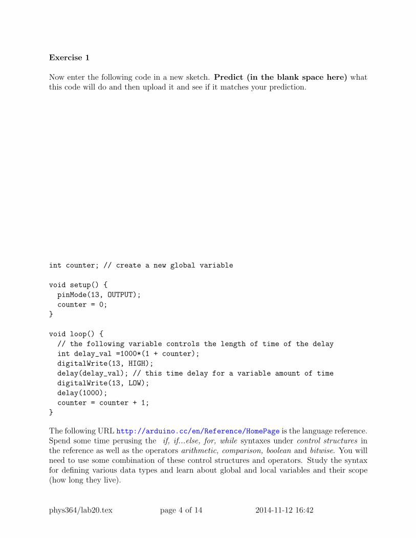
// the setup routine runs once when you press reset:
void setup()
// initialize the digital pin as an output.
pinMode(led, OUTPUT);
// the loop routine runs over and over again forever:
void loop()
digitalWrite(led, HIGH); // turn the LED on (HIGH is the voltage level)
delay(1000); // wait for a second
digitalWrite(led, LOW); // turn the LED off by making the voltage LOW
delay(1000); // wait for a second
Every sketch has two functions: setup() and loop() (this is a departure from C ). The setup( )function is run first and only once, and then loop() keeps repeating the statements withinthe loop() function. Statements within the curly brackets of a function are executed by thefunction. The statement
int led = 13;
sets a variable led to the integer value 13. Every statement must be terminated with asemicolon ;. The statement
pinMode(led, OUTPUT);
sets the digital pin 13 to be an output. The line
digitalWrite(led, HIGH);
sets pin 13 on the Arduino board to HIGH (5V).
delay(1000);
sets a delay of 1000ms before the next statement is executed. Anything after // on a line isa comment and is ignored by the program. The void before each function tells the programthat the function returns nothing when it ends.
The sketch can be compiled from the sketch menu. Pressing the arrow button on the menubar compiles, uploads and runs the executable file on the Arduino board. While the Arduinoboard is being uploaded, you should see the RX and TX LEDs on the board blink rapidly.When the BLINK program runs, the LED connected to pin 13 should blink on and off everysecond (digital pin 13 is the only pin with an associated led).
Change the blink time to 200ms, then compile and upload the sketch. The LED should blinkat 200ms. Save the program with a new name, for example, “myBlink” (You may want tosave it in a different folder than the folder that is selected.)
phys364/lab20.tex page 3 of 14 2014-11-12 16:42
Exercise 1
Now enter the following code in a new sketch. Predict (in the blank space here) whatthis code will do and then upload it and see if it matches your prediction.
int counter; // create a new global variable
void setup()
pinMode(13, OUTPUT);
counter = 0;
void loop()
// the following variable controls the length of time of the delay
int delay_val =1000*(1 + counter);
digitalWrite(13, HIGH);
delay(delay_val); // this time delay for a variable amount of time
digitalWrite(13, LOW);
delay(1000);
counter = counter + 1;
The following URL http://arduino.cc/en/Reference/HomePage is the language reference.Spend some time perusing the if, if...else, for, while syntaxes under control structures inthe reference as well as the operators arithmetic, comparison, boolean and bitwise. You willneed to use some combination of these control structures and operators. Study the syntaxfor defining various data types and learn about global and local variables and their scope(how long they live).
phys364/lab20.tex page 4 of 14 2014-11-12 16:42
Exercise 2
Next modify your program to make the LED blink exactly 10 times and then turn off. Youshould write two sketches, one with an if control structure and the other with a for controlstructure. If you are stuck, you may find it helpful to look at an example sketch illustratingthe use of the if and for control structures. (Briefly summarize below how you modi-fied your program.)
phys364/lab20.tex page 5 of 14 2014-11-12 16:42
Exercise 3
Wire up digital pins 2 to 7 to make a 6-bit LED display on a breadboard. Each pin in outputmode is either HIGH (5 V) or LOW (ground). Remember to connect one of the three groundpins on the Arduino board to the ground on your breadboard. Include a 200 Ω resistor inseries with each LED to limit the current to the LED. Write a program that causes the LEDdisplay to “count” from 0 (all LEDs off) to 63 (all LEDs on) in binary on your LED with,for example, one second between changes in value.
There are many ways to write a program that will accomplish the above task. One way usesa “bit mask.” In order to get a specfic bit of a variable, one normally uses a mask and the &operator; for more information, take a look at http://arduino.cc/en/Reference/BitwiseAnd.For example, if we wanted to just read the fourth bit of the integer variable num, we woulduse the command:
int val = num & 0b1000;
0b indicates that the number is in binary format and 1000 is the binary representation of 8.If the binary representation of num has a 0 in the fourth bit, then this operation will set valto 0; if the binary representation of num has a 1 in the fourth bit, then this operation willset val to 8. The command
digitalWrite(pin, val)
will set pin to LOW if val is zero and HIGH if val is not zero.Another way to do this is with the bitRead command,
bit = bitRead(num, n);
where num is the variable to be read, n is the bit to be read (0 is the least significant bit,following the example above, n = 4), and the variable bit is either set to 0 or to 1.
Briefly summarize, either here or on the following blank page, how you accom-plished this task.
When you are done, keep your LEDs connected, as you will need them forExercise 4.
phys364/lab20.tex page 6 of 14 2014-11-12 16:42

phys364/lab20.tex page 7 of 14 2014-11-12 16:42

Exercise 4
Write a sketch that starts counting when one button—the count button—is pressed andheld. When the count button is released, the counter should stop counting. If the countbutton is pressed and held again, the counter should resume counting from where it left off.When a second button—the reset button—is held pressed, the counter should reset to 0.This is similar to what a stopwatch does.
In order to read the state of your input pins, you can use the command:
val = digitalRead(inputPin);
where inputPin is your chosen input pin.
1k
5V (from Arduino)
InputArduino
Figure 3: Left: a four-pin switch. Two pairs of pins are connected together, and these twopairs are then connected by holding down the switch. Right: schematic for connecting theswitch to the Arduino
Use two switches which look like the image shown on the left-hand side of Fig. 3. Usinga multimeter, determine which pins are connected when the button is held pressed (thistype of switch is called a “momentary” switch). Two pairs of pins are always connectedindependent of whether the button is pressed or not. The switch is constructed in this way(as opposed to just having two pins) presumably for mechanical stability. The pin of theswitch that is connected to the input of the Arduino board should be connected to groundwith a 1 k resistor as depicted on the right-hand side of Fig. 3. The 1 k resistor is neededbecause otherwise when the button is not pressed, the input is floating and in an undefinedstate. The other side of the switch should be connected to the 5 V pin of the Arduino board.
Briefly summarize, on the following blank page, how you accomplished this task.
phys364/lab20.tex page 8 of 14 2014-11-12 16:42

phys364/lab20.tex page 9 of 14 2014-11-12 16:42
Exercise 5
The final exercise is to display the output of your counter on your laptop. To do this youwill have to add to your setup() loop the following line:
Serial.begin(9600); // This sets up serial communication to the laptop
In the loop section add the following lines:
Serial.print("\t counter = ");
// prints a tab followed by counter =
Serial.println(counter);
// prints value of the counter variable and adds a newline.
To see the output on the laptop screen select Serial Monitor from the Tools menu of theArduino IDE. Check if the count displayed on the laptop corresponds with the binary count.
phys364/lab20.tex page 10 of 14 2014-11-12 16:42
Optional 6: reaction timer
Using one push-button input (with connection to +5 V and pull-down resistor to ground)and one LED (with current-limiting series resistor), make a reaction timer that measureshow quickly your finger responds to a visual stimulus from the Arduino.
The Arduino should first turn on the LED, then wait for you to press a button. Onceyou press the button, the Arduino should turn off the LED, then delay a length of time1000 ms < ∆t < 5000 ms, then turn on the LED. The Arduino then measures how longit takes before you respond by pressing the button. As soon as you press the button, theArduino turns the LED off, then reports (via Serial.print() to the serial console) thenumber of milliseconds that it took you to react. After another brief delay, the Arduinoturns the LED back on and returns to the initial state.
If you do this exercise, you don’t need to write anything down, but please callus over so that you can show off your results!
phys364/lab20.tex page 11 of 14 2014-11-12 16:42
Optional 7: musical tones
First make a sketch whose loop() function first outputs HIGH on pin 8, then waits 1.136 msby calling delayMicroseconds(1136), then outputs LOW on pin 8, then once again callsdelayMicroseconds(1136). Check with your oscilloscope that the result is a 440 Hz squarewave on pin 8.
Now notice that the same result can be achieved much more easily by calling the built-infunction tone(pin, frequency) where in this case pin = 8 and frequency = 440. You canalso call tone(pin, frequency, duration) where duration is in milliseconds.
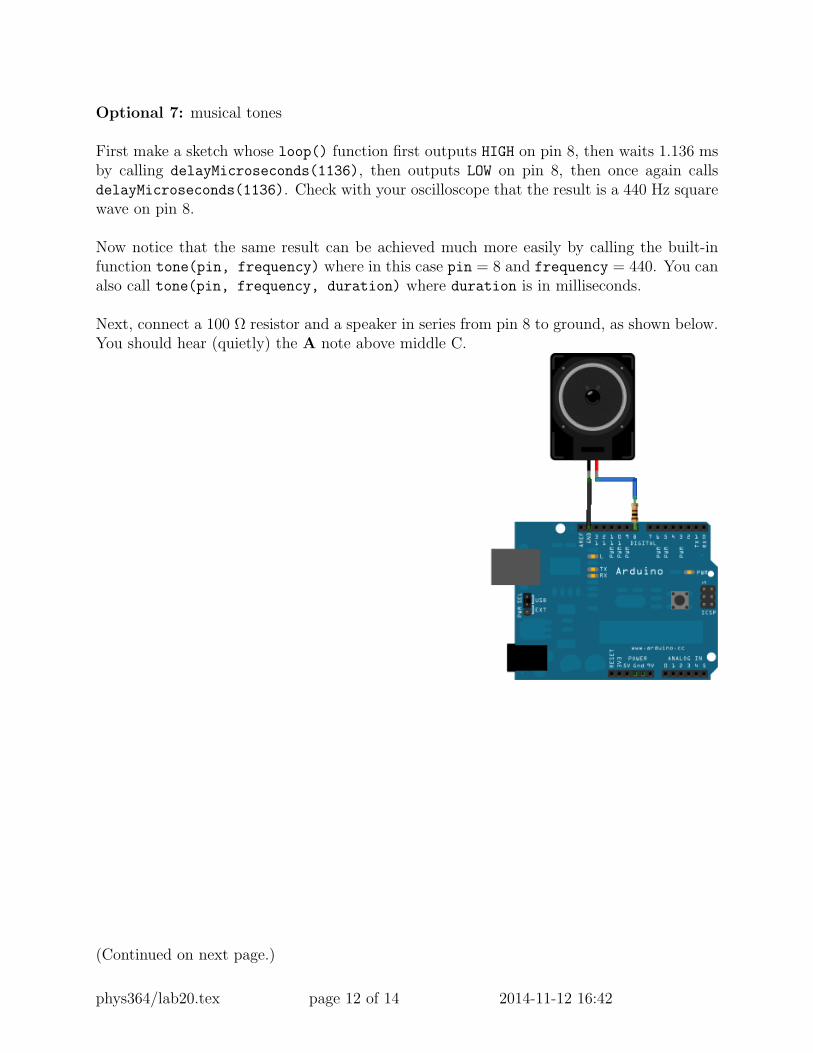
Next, connect a 100 Ω resistor and a speaker in series from pin 8 to ground, as shown below.You should hear (quietly) the A note above middle C.
(Continued on next page.)
phys364/lab20.tex page 12 of 14 2014-11-12 16:42
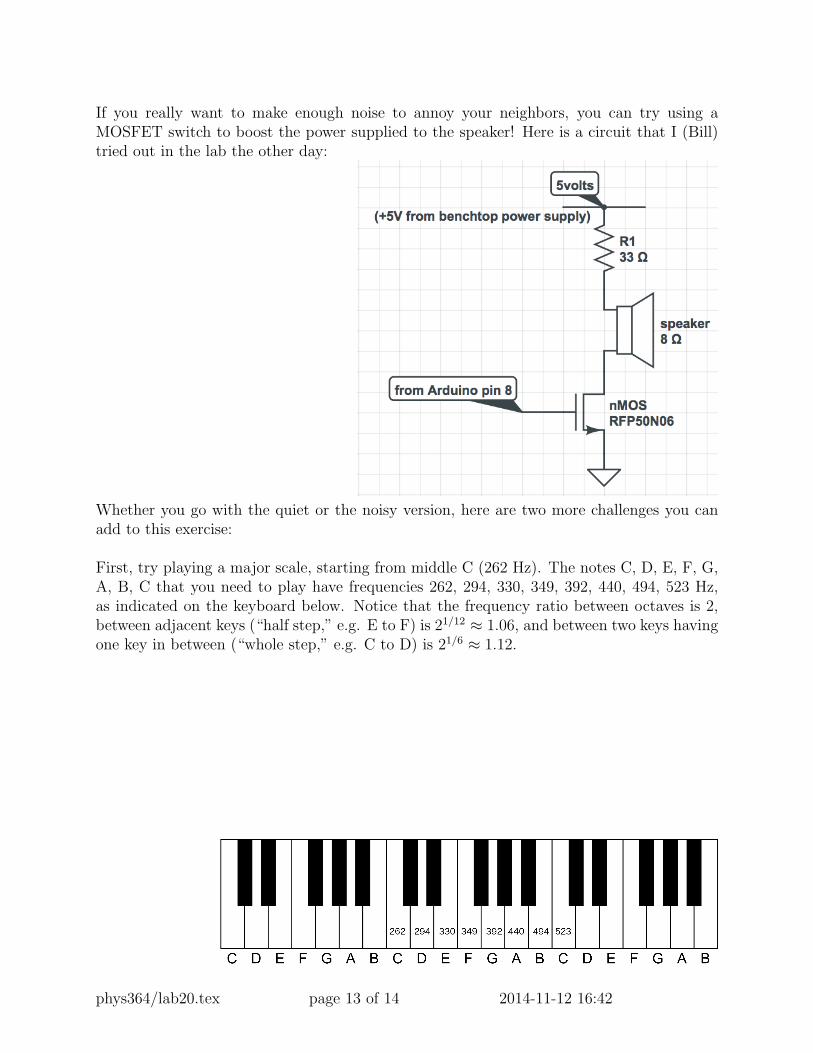
If you really want to make enough noise to annoy your neighbors, you can try using aMOSFET switch to boost the power supplied to the speaker! Here is a circuit that I (Bill)tried out in the lab the other day:
Whether you go with the quiet or the noisy version, here are two more challenges you canadd to this exercise:
First, try playing a major scale, starting from middle C (262 Hz). The notes C, D, E, F, G,A, B, C that you need to play have frequencies 262, 294, 330, 349, 392, 440, 494, 523 Hz,as indicated on the keyboard below. Notice that the frequency ratio between octaves is 2,between adjacent keys (“half step,” e.g. E to F) is 21/12 ≈ 1.06, and between two keys havingone key in between (“whole step,” e.g. C to D) is 21/6 ≈ 1.12.
phys364/lab20.tex page 13 of 14 2014-11-12 16:42
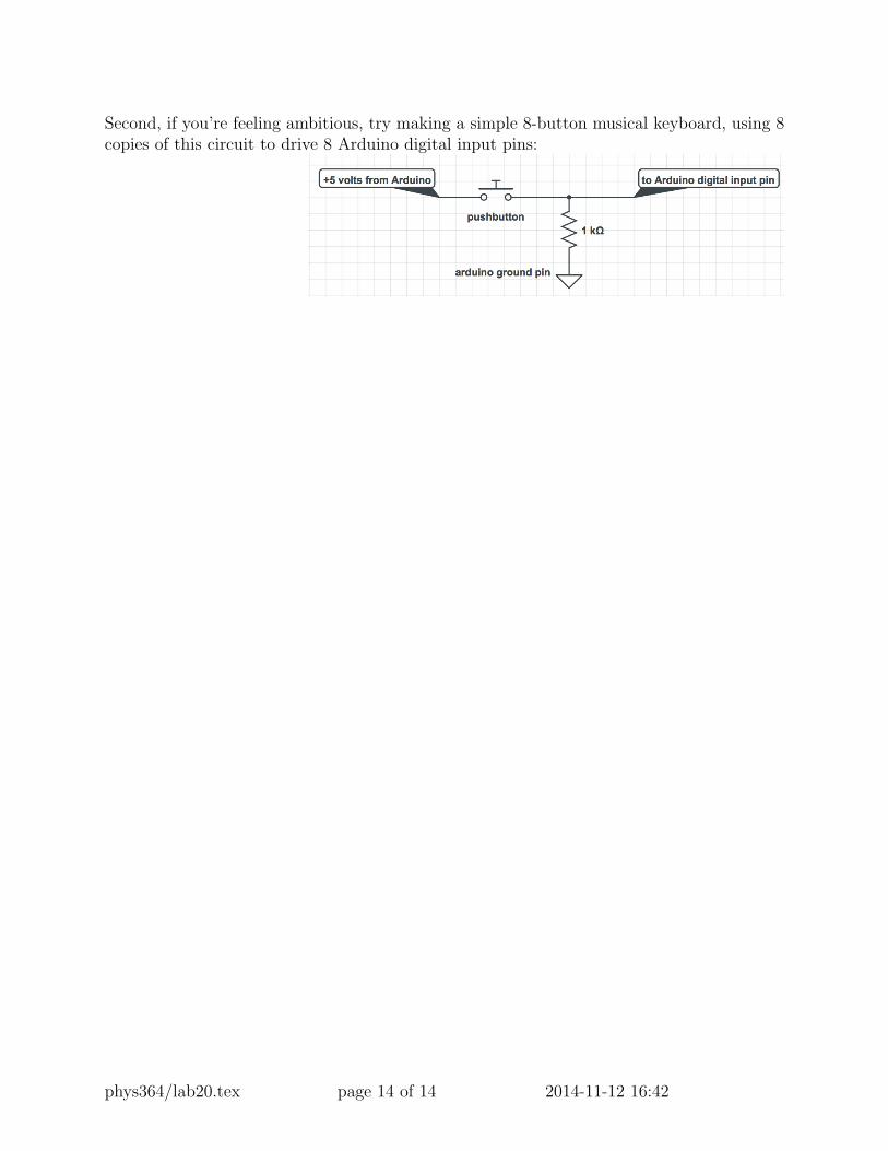
Second, if you’re feeling ambitious, try making a simple 8-button musical keyboard, using 8copies of this circuit to drive 8 Arduino digital input pins:
phys364/lab20.tex page 14 of 14 2014-11-12 16:42