Physical and Virtual Tools: Activity Theory Applied to the ...
29
1 Physical and Virtual Tools: Activity Theory Applied to the Design of Groupware MORTEN FJELD 1 , KRISTINA LAUCHE 2 , MARTIN BICHSEL 3 , FRED VOORHORST 1 , HELMUT KRUEGER 1 , MATTHIAS RAUTERBERG 4 1 Institute for Hygiene and Applied Physiology (IHA), Swiss Federal Institute of Technology (ETH), Clausiusstr. 25, CH-8092 Zurich, Switzerland 2 Institute for Work and Organisational Psychology (IfAP), Swiss Federal Institute of Technology (ETH), Nelkenstr. 11, CH-8092 Zurich, Switzerland 3 Institute of Mechanical Systems (IMES), Swiss Federal Institute of Technology (ETH), Tannenstr. 3, CH-8092 Zurich, Switzerland 4 Center for User-System Interaction (IPO), Technical University Eindhoven (TUE), Den Dolech 2, NL-5612 AZ Eindhoven, The Netherlands Contact: [email protected], www.fjeld.ch, color version: www.fjeld.ch/cscw Abstract. Activity theory is based on the concept of tools mediating between subjects and objects. In this theory, an individual’s creative interaction with his or her surroundings can result in the production of tools. When an individual’s mental processes are exteriorized in the form of tools - termed objectification - they become more accessible to other people and are therefore useful for social interaction. This paper shows how our understanding of activity theory has shaped our design philosophy for groupware and how we have applied it. Our design philosophy and practice is exemplified by a description of the BUILD-IT system. This is an Augmented Reality system we developed to enhance group work; it is a kind of graspable groupware which supports cooperative planning. The system allows a group of people, co-located around a table, to interact, by means of physical bricks, with models in a virtual three-dimensional (3D) setting. Guided by task analysis, a set of specific tools for different 3D planning and configuration tasks was implemented as part of this system. We investigate both physical and virtual tools. These tools allow users to adjust model height, viewpoint, and scale of the virtual setting. Finally, our design practice is summarized in a set of design guidelines. Based on these guidelines, we reflect on our own design practice and the usefulness of activity theory for design. Key words: Design, activity theory, Augmented Reality, Virtual Reality, graspable, groupware, objectification, physical tools, virtual tools, co-located interaction, cooperation, planning, configuration, social, computer. 1. Introduction The aim of this paper is to explain and illustrate our design philosophy for developing graspable groupware. Our philosophy is based mainly on the concepts of tools and exteriorization found in Leont’ev’s (1978, 1981) and Engeström’s (1990, 1996) work on activity theory. Our practice rests on Bødker’s (1991) and Kaptelinin’s (1996) work, where they apply activity theory to human-computer interaction. In our construction of a system we employed a recent technology
Transcript of Physical and Virtual Tools: Activity Theory Applied to the ...

1
Physical and Virtual Tools: Activity TheoryApplied to the Design of Groupware
MORTEN FJELD1, KRISTINA LAUCHE2,
MARTIN BICHSEL3, FRED VOORHORST1,
HELMUT KRUEGER1, MATTHIAS RAUTERBERG41 Institute for Hygiene and Applied Physiology (IHA), Swiss Federal Institute of Technology (ETH),
Clausiusstr. 25, CH-8092 Zurich, Switzerland2 Institute for Work and Organisational Psychology (IfAP), Swiss Federal Institute of Technology (ETH),
Nelkenstr. 11, CH-8092 Zurich, Switzerland3 Institute of Mechanical Systems (IMES), Swiss Federal Institute of Technology (ETH),
Tannenstr. 3, CH-8092 Zurich, Switzerland4 Center for User-System Interaction (IPO), Technical University Eindhoven (TUE),
Den Dolech 2, NL-5612 AZ Eindhoven, The Netherlands
Contact: [email protected], www.fjeld.ch, color version: www.fjeld.ch/cscw
Abstract. Activity theory is based on the concept of tools mediating between subjects and objects. In thistheory, an individual’s creative interaction with his or her surroundings can result in the production of tools.When an individual’s mental processes are exteriorized in the form of tools - termed objectification - theybecome more accessible to other people and are therefore useful for social interaction. This paper shows howour understanding of activity theory has shaped our design philosophy for groupware and how we haveapplied it. Our design philosophy and practice is exemplified by a description of the BUILD-IT system. Thisis an Augmented Reality system we developed to enhance group work; it is a kind of graspable groupwarewhich supports cooperative planning. The system allows a group of people, co-located around a table, tointeract, by means of physical bricks, with models in a virtual three-dimensional (3D) setting. Guided by taskanalysis, a set of specific tools for different 3D planning and configuration tasks was implemented as part ofthis system. We investigate both physical and virtual tools. These tools allow users to adjust model height,viewpoint, and scale of the virtual setting. Finally, our design practice is summarized in a set of designguidelines. Based on these guidelines, we reflect on our own design practice and the usefulness of activitytheory for design.
Key words: Design, activity theory, Augmented Reality, Virtual Reality, graspable, groupware,objectification, physical tools, virtual tools, co-located interaction, cooperation, planning, configuration,social, computer.
1. Introduction
The aim of this paper is to explain and illustrate our design philosophy fordeveloping graspable groupware. Our philosophy is based mainly on the conceptsof tools and exteriorization found in Leont’ev’s (1978, 1981) and Engeström’s(1990, 1996) work on activity theory. Our practice rests on Bødker’s (1991) andKaptelinin’s (1996) work, where they apply activity theory to human-computerinteraction. In our construction of a system we employed a recent technology

2
called Augmented Reality (AR). Before we began to develop the system, westudied users needs by employing task analysis methodology.
According to Leont’ev, not only is activity shaped by physical surroundings,activity in turn shapes the surroundings. When activity shapes those surroundingswhat happens is that internal mental activity materializes into artifacts. Thisprocess of turning mental activity into an object or objectification is whatLeont’ev called exteriorization. While it is obvious that for any individual themoment of exteriorization is an important step in his or her creative designactivity, it is perhaps less obvious that this is a crucial step in making ideasaccessible to others. From this perspective exteriorization is an important socialmoment which supports mutual understanding in a collective creative designprocess.
In our design philosophy we take account of the physical and socialsurroundings as well as the physical and mental faculties of human beings. Wedraw on Bødker’s (1991) and Kaptelinin’s (1996) work as a basis for our designprocess. While we do not consider aspects of human consciousness andemotionality in our current paper, we note the possible connection between theseaspects and human-computer interaction (Nardi, 1996b).
A vital part of our design philosophy is the tradition of AR, which enrichesnatural communication with virtual features. Backed up by activity theory and theusage of AR, we developed groupware for layout planning and configurationtasks; this groupware is called the BUILD-IT system (Rauterberg et al., 1997a,1997b, 1998; Fjeld et al., 1998a, 1998b, 1998c, 1999a, 1999b, in press). Thissystem enables end-users, grouped around a table, to cooperate in the activedesign of a virtual setting, thus supporting co-located, instead of distributed,interaction. The multi-user functionality of BUILD-IT overcomes a seriousdrawback often seen with computer-supported cooperative work (CSCW)systems, namely that they are based on single-user applications (1) (Grudin, 1988).We believe that co-location is an indispensable factor for the early stages of acomplex planning process. Input and output, however, can be prepared and furtherdeveloped off-line, using a conventional Computer-Aided Design (CAD) system.Other major projects where graspable groupware was constructed to supportplanning processes are the metaDESK (Ullmer and Ishii, 1997) and theEnvironment and Discovery Collaboratory (EDC) (Arias et al., in press).
Section 2 introduces our theoretical background, which stems from activitytheory; we discuss concepts such as tools, objectification and collective actionregulation. The difference between goal-directed pragmatic action andexploratory epistemic action is emphasized. Section 3 describes our designphilosophy in terms of AR. Task analysis and the incorporation of both physicaland virtual tools are two methods which we show to emerge naturally out of ourdesign philosophy. Section 4 demonstrates how our design philosophy was usedto develop the groupware called BUILD-IT. Our design philosophy issubsequently applied to the design of tools for graspable groupware. We describe

3
the basic principles of human interaction with graspable tools and show how suchtools are developed according to the results of task analysis, whereby we focus onthe challenges and problems we encountered. In Section 5, the benefits of activitytheory for groupware design are discussed and a set of design guidelines isoutlined.
2. The concept of tools in activity theory
To provide a theoretical background, we show how our understanding of activitytheory has shaped our goals and the design process of AR groupware. First, ouraccount of the tool concept and objectification is given. Then, collective actionregulation is explained. Finally, we introduce two types of complete actionregulation cycles for goal-directed pragmatic action and for exploratory epistemicaction.
2.1 TOOLS AND OBJECTIFICATIONS
In the most general sense, activity means a subject’s interaction with his or hersurroundings. Modern activity theory originated from Soviet cultural-historicalpsychology (Vygotsky, 1978; Leont’ev, 1978, 1981), which in turn is rooted inboth eighteenth and nineteenth century classical German philosophy - fromHegel’s idealism to the historical materialism of Marx and Engels, in which theconcept of activity was extensively elaborated. These roots are quite unfamiliar tomost Anglo-American readers and have therefore been partly neglected (Kuutti,1996). Yet, Engeström (1991) claims that activity theory today is transcendingthese origins, becoming truly international and multidisciplinary. Two results ofthis development are Engeström and Middleton (1996) and Nardi (1996a).
Fundamental to modern activity theory is the idea that the development ofthoughts and cognitive activity requires social interaction and exchange with aphysical environment. Via the process of internalization, social interaction turnsinto mental activity. Handling ever more abstract objects and concepts is part ofan individual’s cognitive development. Nevertheless, the physical environmentremains important, since it is used for the externalization of thoughts and asexternal memory. This is particularly important for the abstract planning andconfiguration tasks we focus on in this paper.
Individuals are confronted with tasks that life puts in front of them and they useartifacts as tools or create tools out of their understanding. These tools thenbecome part of the cultural context of other people. A tool mediates an activity,thereby connecting a human being, not only to the world of objects - his or herphysical surroundings - but also to other human beings. At the same time the useof a tool appropriates the collective experience of humanity embodied in that tool(Leont’ev, 1982). In this sense we view the developmental processes of humanbeings, their physical surroundings and social culture as co-evolutionary. As

4
Engeström (1991) puts it: “The idea is that humans can control their own behavior– not ‘from the inside’, on the basis of biological urges, but from the outside,using and creating artifacts”.
For planning activities Engeström’s idea has been applied to artifacts and tools,resulting in sketches, documents, and three-dimensional (3D) objects or devices.(At this point in our research process, we view Engeström’s artifacts and tools ascorresponding to Leont’ev’s (1978) objectifications of physical nature.) Hacker etal. (1998) describe the importance of grasping design ideas by sketching and bylow-cost prototyping. Such methods may help to achieve design results in a fasterand better way than by using abstract design processes. Physical interactionhandles, for instance bricks (Fitzmaurice et al., 1995), can be seen as physicaldevices for exteriorization in a planning process.
To illustrate the tradition of tool development in activity theory, a historicexample might be of interest. In the historical collection of the ETH library, wefound that mathematicians of the eighteenth century (Diderot and D’Alembert,1778) employed a variety of physical tools (2) (Fig. 1). Modern mathematics hasbecome even more an abstract field of study.
Figure 1. Tool production during the eighteenth century (Diderot and D’Alembert, 1778).
However, the view of tools presented above can also impose some limitationson the potential applications of activity theory. In Virtual Reality (VR) “the borderbetween a tool and reality is rather unclear; information technology can providethe user not only with representations of objects of reality but also with a sort ofreality as such, which does not obviously represent anything else and is intendedto be just one more environment with which the individual interacts” (Kaptelinin,1996, p. 64). This unclear border is a problem VR presents to activity theory; itmight be solved by enriching activity theory’s basic principles with new ideasfrom cultural-historical traditions or other approaches for studying the use ofartifacts.
One answer may be found in the distributed cognition approach, in whichinternal and external representations of artifacts are examined (Flor and Hutchins,1991; Hutchins 1991). As in activity theory, this approach describes how we maytake advantage of artifacts designed by others in collaborative manipulation.Compared with activity theory, “distributed cognition has taken most seriously the

5
study of persistent structures, especially artifacts” (Nardi, 1996c, p. 85). However,the two closely related frameworks show one distinct difference. In activity theoryartifacts mediate human thought and human behavior and there is no intrinsicsymmetry between people and their tools. Based on the 19th century debates onepistemology and on what a human being is, gaining knowledge can be seen as anindividual process, a process of knowing, which can only take place in anindividual. In contrast, distributed cognition puts people and things at the samelevel; they are both ‘agents’ in a system (Nardi, 1996c, p. 86). Hence, thedistributed cognition approach ignores the faculties of human beings not foundwithin computers, like motive, emotionality, and consciousness. It also ignores forcomputers their non-human traits, namely their ability to execute programs in aprecise and predictable manner. By focusing on a common capability of humansand computers, much is lost on both sides.
Another answer is found in Bødker’s (1996, pp. 151-152) characterization ofthe different focuses in the use activity:
• ”The physical aspects - support for operations toward the computerapplication as a physical object. The physical aspects are the conditions forthe physical handling of the artifact. ...
• The handling aspects - support for operations toward the computerapplication. ... The handling aspects are the conditions for transparency ofthe artifact that allow the user to focus on the ‘real’ objects and subjects ofthe activity. ...
• The subject/object-directed aspects - the conditions for operations directedtoward objects or subjects that we deal with ‘in’ the artifact or through theartifact. ... ”
In our work we understand the physical aspects as how to use the hardware tooperate the groupware, the handling aspects as how to operate the groupware, andthe subject/object-directed aspects as how to use groupware to solve a task.
Bødker talks about ‘real’ objects and subjects of the activity. Working withVR, the object of the activity is represented by a virtual world. What a subjectsituated within that virtual world would see, is represented by a virtual viewpoint.By interpreting the term ‘real’ in the handling aspects as ‘virtual’, we mayovercome the limitations pointed out by Kaptelinin (1996), i.e. we may clearlydefine the border between tool and reality. This interpretation takes on particularimportance when we develop our so-called navigation methods (Section 4.3.3),which are purely based on the handling aspects. In a more general way, we willuse all three focuses in the use activity to structure the description of our designprocess (Section 4).

6
2.2 COMMON OBJECTIFICATION
In more recent developments, the scope of activity theory has broadened toencompass interaction within a community (Engeström, 1991). Since our designphilosophy is centered on supporting co-located groups, this new development hasbeen of particular interest to us. As pointed out above, a tool connects anindividual to other human beings by mediating activity, thereby becoming part ofa cultural context. Of particular interest to us are tools that are made or used bygroups.
The individual processes of goal setting, planning, and action are transferredinto collective action regulation (Weber, 1997; 1999). This transfer refers tocoordination and allocation processes within a group. Weber introduces the termcommon objectification to mean materialization of collective action regulation,integrating different schools of activity theory. ”The process of commonobjectification is understood as a process by which all (or several) members of aworkgroup mutually transfer their individual knowledge, expertise, andexperience into a material form. By doing this, they make their materializedknowledge available to other group members” (Weber, 1999, p. 13). First appliedto industrial work groups, common objectification was also found to be of greatimportance in design and planning teams because planning tasks require evenmore mutual exchange of knowledge among experts (Lauche et al., 1999). Theresults of a process of common objectification can take the form of reports, designdocuments, prototypes, drawings, or software. Therefore, it is part of our designphilosophy to facilitate the creation of such results among a group of users.
2.3 GOAL-DIRECTED AND EXPLORATORY ACTION
General models for goal-based problem solving were first suggested by Newelland Simon (1972). Drawing from the same sources as activity theory, actiontheory has focused on goal-directed action at work (Hacker, 1994; Frese and Zapf,1994; Volpert et al, 1989; Frese and Sabini, 1985). Hacker (1998) introduced thenotion of complete action cycle (Fig. 2) for goal-directed pragmatic action,consisting of:
(1) setting the next (or first) goal in performing a task,(2) planning according to the conditions of execution, including selection of
tools and preparation of actions necessary for goal attainment,(3) physical (or even mental) performance, and(4) control according to the set goal via different sources of feedback.

7
feedback planning
goal setting
action
task
Figure 2. A complete action cycle for goal-directed pragmatic action as suggested by Hacker,1994. Action is derived from goal setting.
In our work, however, we have realized that both our own design process andthe planning task for which we are designing the groupware are not exclusivelygoal-directed; they also have exploratory elements. Exploratory epistemic actions(Kirsh and Maglio, 1994) are performed to unveil hidden information or to gaininsight that would otherwise require a great deal of mental computation.Exploratory epistemic action means that no specific goal is available for initialaction. Only after the receipt of feedback, which gives information on the meansavailable, can a goal be generated. Based on this goal, a new planning stage and anew action phase can be initiated. Thereby, an alternative kind of complete actioncycle emerges (Fig. 3).
planning feedback
action
goal setting
task
Figure 3. A complete action cycle for exploratory epistemic action. Goal setting is derived fromaction.
Our aim will be to design a system which fluently mediates both kinds ofactions, goal-directed pragmatic and exploratory epistemic action.
3. Design philosophy
In this section we present our design philosophy, which is based on coincidingaction and perception spaces, in its relation to Augmented Reality (AR). Taskanalysis and a shifting design focus between physical and virtual tools aredescribed as two further design methods emerging from our philosophy.

8
3.1. AUGMENTED REALITY
Computer-supported cooperative work (CSCW) has enabled distant andasynchronous communication between people and has helped build ‘bridges’ inour global economy. This has brought about many well-advertised advantages,ranging from economic benefit to less status-oriented network communication.However, with many CSCW systems, users hardly interact with their physicalenvironment. They deal only with virtual objects, which is also the case for mostsingle-user applications. Sometimes users are even embedded in a fully virtualworld, unable to draw on any attributes of the tangible physical world. Much ofthe users’ mental capacity is employed to adapt to the virtual world, leaving lesscapacity for actual task solving.
An alternative approach offered by AR is to bring the virtual world ofcomputers into the physical world of everyday human activity. This approachincludes aspects of natural communication which serve as mediators for mutualunderstanding: eye-contact, body language, and physical object handling. It isnon-intrusive (Vince et al., 1999), using no gloves or helmets, and therebyrespects body-space (Rauterberg, 1999). At the same time users can still draw onthe advantages of a virtually enriched world, which is of particular importance toplanning tasks. The activity of planning is mainly ‘virtual’ because it involvesreflecting on and modifying objects that will only exist in the future. Virtualmodels of these objects can be more easily changed than physical models (3). Theycan be stored in external computer memory and can be visualized for interactionpurposes. Thus both physical and virtual models have their rightful place in aplanning process. A specific aim of our project is to study ways to integratecomputer-mediated activity into the physical world. This is how we came to workwithin the tradition of AR, where computer-generated models and physical objectsare handled in one workspace.
Figure 4. AR means that a physical workspace (left) is augmented, or enriched, by a virtual world(right). Even when users interact with the projected, virtual models, they do not leave the physicalcontext (e.g. sketching) and tools (e.g. pencil).
AR was first described by Wellner et al. (1993) and Mackay et al. (1995). Thegoal of AR is to “allow users to continue to use the ordinary, everyday objectsthey encounter in their daily work and then to enhance or augment them withfunctionality from the computer” (Mackay et al., 1995). According to Mackay,

9
AR means that computer information is projected onto drawings so that users caninteract with both the projected information and the paper drawing. The firstbrick-based AR system was described by Fitzmaurice et al. (1995). A more recentexample of how AR can be used to support urban planning is given by Arias et al.(in press). Their focus is to create “shared understanding among variousstakeholders... [by] ...creating objects-to-think-with in collaborative designactivities.” (Arias et al., in press). Figure 4 illustrates some of these principles.Pen-based input has been studied extensively; in this paper we look at bricks asinput medium.
3.2. ACTION AND PERCEPTION
In his ‘Writings on the philosophy of making’ Aicher (1996) criticizes the lack ofdoing by planners and the overemphasis on the reduction of real-life to inner,rational activity. He advocates a closer connection between action and mentalreflection, indicating a need to enable users to bring together action and reflectionin human computer interaction. For our design practice this means to “createpossibilities for the users to try out the user interface through use, not onlythrough reflection” (Bødker, 1991, p. 148). Hence, people must be able to employtheir everyday motor faculties in their interaction with computers. We set out tocreate an interface with various input modes and tactile interaction. Thisdemanded a user interface able to interpret a wide range of human expressions.Such interfaces need powerful computer vision methods (Rauterberg et al.,1997b).
A further important aspect of our design philosophy is the coincidence ofaction and perception space (Rauterberg, 1995). When handling physical objects,the space in which we act coincides with the space from which we receive (visual)feedback: we can see what we do. This is not the case for the handling of virtualmodels with a mouse-keyboard-screen interface, where there is a separationbetween action and perception spaces. Input and output devices are separated. Toovercome this separation, Rauterberg (1995) suggested an alternative approach tointerface design, an approach where action space and perception space coincide.Support is given by Hacker and Clauss (1976), who found that performanceincreases when task relevant information is offered in the same space where actiontakes place. This principle not only applies to visual but also to haptic or tactilefeedback. Akamatsu and MacKenzie (1996) showed how including tactilefeedback might improve computer-involved, task-solving performance.
3.3. TASK ANALYSIS AS PART OF THE DESIGN PROCESS
An integral part of our design philosophy is to gain a detailed understanding of thetarget activity: cooperative planning. For CSCW it is of particular importance toinvestigate which part of an activity is of a genuine cooperative nature and which

10
part merely employs computers for individual work.In the tradition of socio-technical systems theory (Emery, 1959), a task is seen
as the link between the human/social system and the computer/technical system.Based on this tradition, it is not sufficient to take end-user expectations andpreferences as guidelines for future design. Such a strategy would focus on what isalready available and would be of little use for innovative breakthroughs. Forinstance, end-users would project their understanding of existing CADfunctionality onto new interfaces without taking into consideration the wholesocio-technical system they are part of. Therefore, instead of taking account ofcurrent personal and technical constraints, our analysis focuses on the task.
The strategy of our task analysis was to interview planning experts and observetheir working processes, then to elicit difficulties with the predominant socio-technical system of meetings, drawings, and single-user CAD applications. Theexperts explained their jobs and provided examples of objectifications they used.Also, interaction with colleagues and customers was part of the interview. Theresults were used to make decisions about future directions in our design.
3.4. EXTERIORIZATION AND INTERIORIZATION OF TOOLS
Through our own design practice (Section 4.2) we made the followingobservations, valid from both a designer and from an end-user point of view.Before users had gained experience with physical tools (first step), user operationof the system was slow. Section 4 offers a few examples, for instance the initialbricks (Fig. 8, right, in center) and the first generation virtual tool for changingmodel height (Fig. 9). Once physical tools were available and mastered (secondstep), they became beneficial to task solving. This was the case for the morerecent bricks (Fig. 8, right) and the physical tools for changing model height (Fig.10). Based on our understanding of activity theory, we noticed that the physicaltools used in the second step were an exteriorization of the knowledge we gainedfrom our collective design activity (Section 2.2). Based on the experience gainedwith physical tools, we even saw one case where a second generation virtual toolcould replace the physical ones (third step). This was the case for an elaboratedvirtual tool for changing model height (Figs. 11-12). In the transition from thesecond to the third step the knowledge acquired using the physical tool was partlyinternalized (e.g. by giving our design team a common reference about the use ofphysical tools, even though not in use), partly implemented in the virtual tool (e.g.by mapping physical buttons onto virtual handles).

11
We observed that our experience is close to an idea of Kaptelinin (1996, p. 62),describing a three-step development of tool usage:
1. ”The initial phase, when performance is the same with and without a toolbecause the tool is not mastered well enough to provide any benefits,
2. the intermediate stage, when aided performance is superior to unaidedperformance, and
3. a final stage, when performance is the same with and without the tool butnow because the tool-mediated activity is internalized and the external tool(such as a checklist or a visualization of complex data) is no longer needed.”
Since the three steps we observed and Kaptelinin’s idea have important pointsin common, we employed his idea as a justification for a repeatedly shiftingdesign focus between virtual and physical tools.
4. Design example: the BUILD-IT system
BUILD-IT is a planning tool based on state-of-the-art computer vision technology(Rauterberg et al., 1997a, 1997b, 1998; Fjeld et al., 1998a, 1998b, 1998c, 1999a,1999b, in press). This system (Fig. 5) enables its users to cooperate in a virtualenvironment for planning a real-world object, such as a room, a school, a factory,or a piazza. Grouped around a table and employing tangible physical bricks, userscan select and manipulate virtual models within the setting which they areplanning. This use of physical bricks represent a new way of interacting. Tetheredbricks (requiring wires or cables) were investigated in the Active Desk byFitzmaurice et al., (1995). Fitzmaurice and Buxton (1997) later developedwireless bricks, detected by using a Wacom board. In the more recent use oftangible bricks, their surface is detected from above (Ishii and Ullmer, 1997;Ullmer and Ishii, 1997; Rauterberg et al., 1997a, Underkoffler and Ishii, 1998). Itwas shown that a brick-based interface is significantly easier to use and moreintuitive than a mouse-keyboard-screen (Rauterberg et al., 1996).

12
Figure 5. BUILD-IT consists of a rack, mirror, table, chairs, and a screen (top left). In addition toa high-end PC, the rack contains two beamers, a video camera, and a light-source. The systemoffers two perspectives of the same setting: a horizontal plan view for combined action andperception and a vertical side view (top right). Models projected in the plan view can be rotatedand positioned using a brick (bottom left). Bimanual interaction is an essential part of theinteraction concept (bottom right).
4.1 BASIC ASPECTS OF THE BUILD-IT SYSTEM
Based on our discussion of tools (Section 2.1), we have chosen to structure thesystem description according the focuses in the use activity (Bødker, 1996, pp.151-152). In this section (Section 4.1), we present all the basic aspects of theBUILD-IT system and its use. In the following section (Section 4.2) we focus onthe design of tools, reflected by the physical aspects and the handling aspects. Adetailed investigation of the subject/object-directed aspects belongs to futureresearch.
4.1.1 Physical aspects of the system
In our system the position and orientation of the brick on the table top isdetermined by a computer vision system. Reflective material is applied to the topof each brick. The bricks reflect light from a light-source to a camera viewing thesurface from above. Image processing software then recognizes the bricks anddetermines the two-dimensional (2D) position and orientation of each (Bichsel,1997). This information is then used to control the groupware and hence update

13
the image projected on the table (4). For the interaction taking place on the table,our technology respects the principle of coinciding action and perception spaces(Section 3.2). For the image projected on the screen, however, the same principleis not respected.
4.1.2 Handling aspects of the system
In BUILD-IT the users have two up-to-date views of the setting they are creatingand manipulating at all times: the plan view and the side view. The plan view isthe bird’s eye view from above - which is projected onto the table. The side viewis projected onto a screen near the table. In the case of the side view, a virtualcamera, which can be located either outside or inside the plan view, allows theusers to choose from which position the side view is to be projected. The sideview can also be zoomed. In the case of the plan view, the entire projection of thesetting can be shifted from side to side, rotated, or zoomed. The plan view alsocontains a virtual storage space for models not in immediate use. It allows users tocreate multiple model instances. A model instance brought back to the storagespace is deleted from the views. For all handling operations affecting virtualmodels users draw on basic, everyday manual skills - selecting, placing, rotating,re-positioning, and fixing.
Figure 6. The basic steps for user manipulations with the brick.
In BUILD-IT mediation between users and the virtual world follows a cyclicorder (Fig. 6). Users select a model by putting the brick at a model’s position. Themodel can be re-positioned, rotated, and fixed by simple brick manipulation. Amodel can be de-selected by covering the brick. Then, another model is selectedor the brick is left idle inside or outside the plan view. Using a material, hand-heldbrick, everyday manual patterns - like grasping, moving, rotating, and covering -are activated. Since all the steps in the cycle are reversible, the cost of making amistake is low. Thus, exploratory epistemic and goal-directed pragmatic actionsare equally supported, as described in Section 2.3. However, there is no possibilityof undoing, so users must keep information about previous steps in their planningprocess. (More comments regarding undo appear later in section 5).

14
4.1.3 Subject/object-directed aspects of the system
The BUILD-IT system can be used by a single individual, but its full potential isrealized as a mediator among members of a work group (Fig. 7). Basic usage ofthe system is acquired within minutes. Therefore, it may stimulate peoplepossessing different sets of skills and/or different modes of knowledge to workcloser together and thereby enhance their (verbal) exchange. Also, since thesystem forces people to work with shared resources, it has a capacity to revealpotential misunderstandings among them. A collective learning process can betriggered through the unifying workspace. This was actually experienced by ourdesign team itself during system development work.
Figure 7. Typical multi-user (left) and single-user (right) situations. Interaction and display takeplace in the plan view, whereas an additional perspective is offered by the side view.
Although we have designed a co-located, multi-user groupware system, thephysical and virtual tools presented in this paper may be important steps towards amulti-site, multi-user system and therefore represent a technological foundationfor CSCW. Based on standard software and hardware, the system will allow for adistributed networking CSCW system in the near future. In our projection of sucha system initial configuration will be transferred at start-up time, then only brickdata will be transferred at real-time. This will allow the use of standard,commercial communication channels.
4.1.4 From CAD to BUILD-IT: A new tool for planning
In most companies CAD systems have replaced drawings and physical models.This change has helped speed up the design process by systematizing recurrenttasks and reducing the monotonous work of small changes. CAD systems aremore than simple drawing tools; they offer interfaces to production monitoringand quality control. In CAD systems part prices or other meta-data can be storedwith 3D data. However, not all planners are yet acquainted with CAD systems.This results in a division of labor between planners and CAD specialists,complicating the planning process. Another drawback of CAD systems is thatthey are not well suited for the early stages of a design process (Hacker et al.,

15
1998) nor for person-to-person or group communication. This is partly becausethey are based on single-user applications (Grudin, 1988).
Our task analysis involved 16 planning experts from the machinery andprocessing industries and from the field of architecture. As a result, wedistinguished three possible domains of use for the BUILD-IT system:1. Cooperative planning among a team of experts: For cooperative work and
concurrent engineering, the BUILD-IT system offers a multi-user interface.This interface may enhance common understanding of an early planningprocess by offering professional tools, like advanced model height adjustmentand full 3D navigation.
2. Interactive planning with customers or clients: In this domain the mostimportant feature is that the customers can easily step into the early planningprocess and visualize their own ideas. Clients who are not used to planning -and thereby not used to 2D views - will be more at home with 3D images. TheBUILD-IT system gives these users an easier access to 3D vision.
3. Marketing: For presentation and marketing purposes, tangible bricks maystimulate intuitive, play-like interaction. Potential clients using the system maybe more involved than in conventional presentations, where interaction is fullycontrolled by a salesperson.
In all three domains BUILD-IT will not replace CAD systems. Rather, it mayserve as a pre-CAD complement in the early stages of design (5). It might alsostimulate the evolution of CAD systems (6).
4.2 DESIGN PRACTICE OF THE BUILD-IT SYSTEM
The challenges we faced were of three kinds. First, there is a potential perceptualproblem for the users. The users employ physical bricks to design and manipulatea virtual setting which is simultaneously projected onto the table on which thebricks are sitting. Thus, the users are living and acting in two realities at once(Section 4.2.1). Designing bricks to link these realities fluently is related to thephysical aspects of the system. Second, we encountered the technological problemof changing model height (Section 4.2.2) related to shifting focuses between thephysical and the handling aspects of the system. The third problem we faced wasa clear mixture of a perceptual problem for the user and a significant technologicalchallenge to us: BUILD-IT uses 2D - or planar - interaction to access a 3D virtualsetting (Section 4.2.3). The answer we found - a set of navigation tools - leveragesalternative handling aspects of our system. The subject/object-directed aspects ofthe system (Section 4.1) will not be discussed any further.
4.2.1 Physical aspects: Brick design
The question related to the physical aspects was how to design an interface whereusers can move physical bricks and simultaneously immerse themselves in a
16
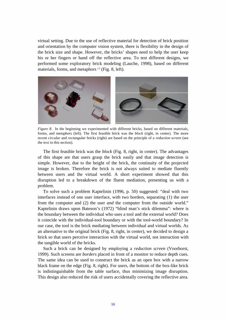
virtual setting. Due to the use of reflective material for detection of brick positionand orientation by the computer vision system, there is flexibility in the design ofthe brick size and shape. However, the bricks’ shapes need to help the user keephis or her fingers or hand off the reflective area. To test different designs, weperformed some exploratory brick modeling (Lauche, 1998), based on differentmaterials, forms, and metaphors (7) (Fig. 8, left).
Figure 8. In the beginning we experimented with different bricks, based on different materials,forms, and metaphors (left). The first feasible brick was the block (right, in center). The morerecent circular and rectangular bricks (right) are based on the principle of a reduction screen (seethe text in this section).
The first feasible brick was the block (Fig. 8, right, in center). The advantagesof this shape are that users grasp the brick easily and that image detection issimple. However, due to the height of the brick, the continuity of the projectedimage is broken. Therefore the brick is not always suited to mediate fluentlybetween users and the virtual world. A short experiment showed that thisdisruption led to a breakdown of the fluent mediation, presenting us with aproblem.
To solve such a problem Kaptelinin (1996, p. 50) suggested: “deal with twointerfaces instead of one user interface, with two borders, separating (1) the userfrom the computer and (2) the user and the computer from the outside world.”Kaptelinin draws upon Bateson’s (1972) “blind man’s stick dilemma”: where isthe boundary between the individual who uses a tool and the external world? Doesit coincide with the individual-tool boundary or with the tool-world boundary? Inour case, the tool is the brick mediating between individual and virtual worlds. Asan alternative to the original brick (Fig. 8, right, in center), we decided to design abrick so that users perceive interaction with the virtual world, not interaction withthe tangible world of the bricks.
Such a brick can be designed by employing a reduction screen (Voorhorst,1999). Such screens are borders placed in front of a monitor to reduce depth cues.The same idea can be used to construct the brick as an open box with a narrowblack frame on the edge (Fig. 8, right). For users, the bottom of the box-like brickis indistinguishable from the table surface, thus minimizing image disruption.This design also reduced the risk of users accidentally covering the reflective area.

17
4.2.2 Shifting between physical and handling aspects: Changing model height
Up until this point, the system placed all models on a single storey. Taskanalysis (Section 4.1.4) showed that potential end-users wanted to be able toposition models on different stories of a building. To do this we used a three-stepdesign process (Section 3.4) suggested by Kaptelinin (1996). In a first step of thatprocess, subjects work with a virtual tool moving single models into a virtualseries of stories. For this step, user performance was not satisfactory and welooked for alternatives. In a second step we tested physical tools which affected aparticular virtual floor. A virtual floor looks like a grid-layer. This grid-layer canbe adjusted upward and downward. The models selected move along with thevertical placement of the virtual floor. Physical tools improved performance buttheir use was too tedious (Fjeld et al., 1999). In a third step, a second-generationof virtual tools was developed, recombining elements of the first and the secondstep. Hence, the virtual floor could be handled with a virtual tool; the physicaltools were no longer needed. The second step was related to the physical aspectsof the system, the first and third steps were related to the handling aspects of thesystem. Each step is described below.
Step 1: A virtual prototype for height manipulation: The height slice
Height manipulation by means of side view handling was first achieved bycopying a narrow vertical slice of the side view, called the height slice, andlocating it along one edge of the plan view. The desired view of the height slice isselected and set by the user. Thus, models appear visible in the height slice, can beselected, and can be moved up and down (Fig. 9). When de-selected, modelsremain at the selected height. Further details are given in Fjeld et al. (1999b).
Figure 9. Setting model height by selecting (left) and moving (center) a model in the height slice.The model being moved is also seen in the side view (right).
Step 2: Physical tools as mediators for model height
Based on physical tools (Fig. 10), we explored three ways to physically handlemodel height. First, we implemented Digit, a digital controller which acts on aselected model and sets the model height by means of up-down buttons andprovides a digital display of the height. Second, we developed Tower, offering thesame buttons as the first tool combined with a luminous, quasi-analog scale

18
showing selected height. The up-down buttons and the visual feedback areorganized along the height axis, so action and perception are partly coincident.Third, we implemented Slider, a vertical sliding-rule where height is handled andindicated by an up-down handle. With Slider, handling and height cues are bothorganized along the height axis; thus action and perception are fully coincident(Section 3.2). Further details are given in Fjeld et al. (1999b).
Figure 10. Physical height tools: Digit, a box with up-down buttons and display; Tower, aluminous scale with up-down buttons; Slider, a sliding-rule with up-down handle and digitaldisplay (left to right).
Step 3: ‘Back to the virtual’: Floor handling
The resulting solution for selection and manipulation of the models selectedamong multiple stories is a virtual tool called Floor and is a second generationvirtual solution. Floor reuses the height slice from the first solution and is basedon the knowledge gained with the second solution. Floor is handled in the heightslice, located along one edge of the plan view. The user first selects a number ofmodels in the plan view, forming a group. This group of selected models thenmoves vertically as a whole when Floor is moved upward or downward in theheight slice (Figs. 11-12). De-selected models remain at the last selected height.Only models at or above Floor are visible. Further details are given in Fjeld et al.(1999b).

19
Figure 11. Selecting models in the plan view; selecting Floor in the height slice; raising Floorwith the group of selected models (left to right).
Figure 12. Side view; selecting and raising Floor with a group of selected models (left to right).
4.2.3 Handling aspects: Spatial navigation
Our task analysis (Section 4.1.4) showed that experts navigate and inspect virtualenvironments in a range of activities, such as urban planning and architecturalwalkthroughs. Depending on a user’s acquaintance with virtual environments,navigation can range from exploratory epistemic to goal-directed pragmaticaction. It is necessary to assume different points of view, to get an overview, andto look at things in detail in a fluent manner (Brooks, 1986).
Our answer to this need is offered by combining tangible bricks with 3D viewhandling of orientation and scale. Brick-based interaction in 2D has already beeninvestigated (Fitzmaurice, 1996, Ullmer and Ishii, 1997). Also, bimanual cameramanipulation and model handling in 3D graphics interfaces have been examined(Balakrishnan and Kurtenback, 1999) using two mice, a keyboard, and a screen.Here, we combine the strengths of these two approaches. The multimediaframework (MET++, Ackermann, 1996) we employ allows for full interaction in a3D world. However, planar interaction with bricks provides only position androtation but not height or inclination information. The resulting navigationmethods are two alternative ways to bridge the gap between planar interaction and3D view handling.
We first considered a design strategy based on the physical aspects, as was thecase for general brick design (Section 4.2.1). This would have resulted in aphysical, camera-like brick affecting the virtual side view camera. Such a solutionwould have required extending the properties sensed by the computer vision input.Based on our experience with the physical height tools (Section 4.2.2), we decidedto explore virtual solutions (Fjeld et al., 1999a). The decision we took, is also

20
supported by Ware and Rose (1999), who examined the use of real handles for therotation of virtual models.
Hence, we investigated a design strategy based on the handling aspects of thesystem. Our strategy was to handle the virtual world or the virtual viewpoint(Section 2.1). This opened up two alternative design principles and both wereinvestigated. First, in order to handle the virtual world - updating the view directly- we implemented the Continuous Update method. Second, in order to handle thevirtual viewpoint - updating the view after viewpoint handling - we implementedthe Select and Reframe method, where a frame represents the border of the planview or the side view. The aim of our future research is to test which of thesedesign principles is best suited for fluent navigation (8).
Each navigation method consists of two tools, one for the plan and one for theside view control (Table I). The tools can be activated in the virtual storage space(Fig. 13). By employing one brick - unimanual handling - shift and rotation of thecontrolled view can be set. By employing two bricks - bimanual handling - shift,rotation, and zoom of the controlled view can be set (9). Bimanual handling will beillustrated here. The two methods can be combined, but only one tool per viewcan be activated and used at a time.
Plan view control
Select and Reframe
Side view control
GroundCatcher FrameCatcher
ViewFrameCamera
Continuous Update
Table I: The symbols used in the menu to represent the tools. There is one method (ContinuousUpdate and Select and Reframe) per column and one view (plan and side view) per row.
Figure 13. The tools are situated in the virtual storage space (menu) on the right.

21
Handling the virtual world: Continuous Update
Handling of the virtual world is implemented in the Continuous Update methodand consists of two tools: GroundCatcher for the plan view and Camera for theside view. These tools work in a similar way. As soon as the GroundCatcher (Fig.14) is selected from the menu and placed, it locks to the setting. All subsequenthandling affects the plan view. To quit the tool, the bricks are covered andremoved. By selecting the Camera (Fig. 15) from the menu, the part of the settingshown in the side view can be set. A zoom handle is selected with a second (here:right hand) brick. By moving the zoom handle and the camera further apart, theside view can be enlarged; by moving them closer, the side view can be focused.Covering and removing the second brick freezes the zoom. The Camera remainsvisible and accessible in the view. Further details are given in Fjeld et al. (inpress).
Figure 14. GroundCatcher: Placing bricks; view handling; removing bricks (left to right).
Figure 15. Camera: Consecutive zoom handling steps (left and center); removingbricks (right).

22
Handling the virtual viewpoint: Select and Reframe
Handling of the virtual viewpoint is implemented in the Select and Reframemethod and consists of two tools: FrameCatcher for the plan view andViewFrame for the side view. Both tools employ a rectangular frame representingthe border of the view.
When the FrameCatcher (Fig. 16) is selected from the menu, the settingautomatically is zoomed out to show a wider context. As soon as theFrameCatcher is placed within the frame, it locks to the frame. All subsequenthandling affects the frame and the desired part of the setting can be selected.Covering and removing the brick triggers a reframe of the view, responding touser selection. When the ViewFrame (Fig. 17) is selected from the menu, the sideview is automatically zoomed out to show a wider context. The desired part of thesetting can be selected. A zoom handle is selected with the second brick, thusresizing the window. Covering and removing the second (here: right hand) brickfreezes the zoom. Covering and removing the first brick triggers a reframe of theside view, responding to user selection. The ViewFrame remains visible andaccessible in the view. Further details are given in Fjeld et al. (in press).
Figure 16. FrameCatcher: Placing bricks (left); selection (center); reframe (right).
Figure 17. ViewFrame: Consecutive selection steps (left and center); reframe (right).
23
5. Conclusion
The aim of this paper is to explain and illustrate our design philosophy fordeveloping graspable groupware; we have focused on describing our experiencewith tool design for planning and configuration tasks. The aim of our work was toenable the exteriorization of end-users’ planning processes. We achieved this goalby designing a graspable interface. With this interface several users cancommunicate and interact in a coincident action perception space and therebyreach common objectification. Our planning tool not only supports goal-directedbut also exploratory action. We took an AR approach where virtual models aremanipulated through physical bricks. In this paper we present examples from ourdesign practice for the physical and the handling aspects (Bødker, 1996) of oursystem. Related to physical aspects, we show how we designed brick. Related toshifting focuses between the physical and the handling aspects, we show how wedeveloped solutions for height adjustment. Related to the handling aspects, weshow how we developed a set of tools for spatial navigation.
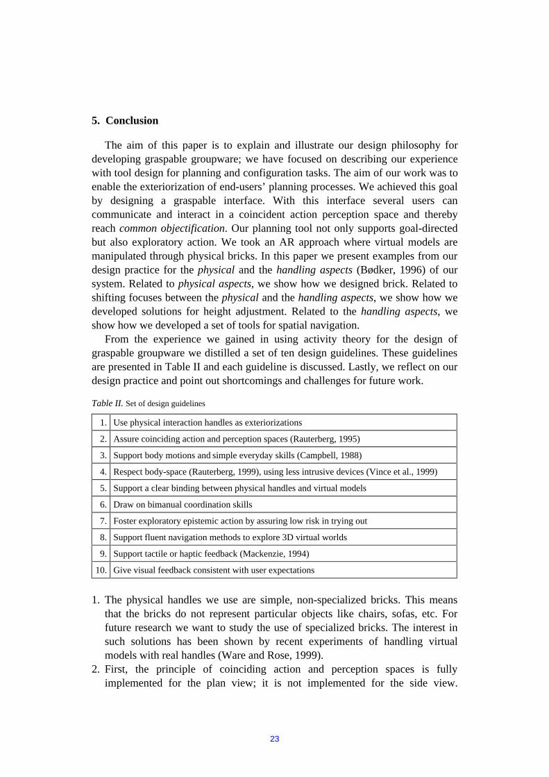
From the experience we gained in using activity theory for the design ofgraspable groupware we distilled a set of ten design guidelines. These guidelinesare presented in Table II and each guideline is discussed. Lastly, we reflect on ourdesign practice and point out shortcomings and challenges for future work.
Table II. Set of design guidelines
1. Use physical interaction handles as exteriorizations
2. Assure coinciding action and perception spaces (Rauterberg, 1995)
3. Support body motions and simple everyday skills (Campbell, 1988)
4. Respect body-space (Rauterberg, 1999), using less intrusive devices (Vince et al., 1999)
5. Support a clear binding between physical handles and virtual models
6. Draw on bimanual coordination skills
7. Foster exploratory epistemic action by assuring low risk in trying out
8. Support fluent navigation methods to explore 3D virtual worlds
9. Support tactile or haptic feedback (Mackenzie, 1994)
10. Give visual feedback consistent with user expectations
1. The physical handles we use are simple, non-specialized bricks. This means
that the bricks do not represent particular objects like chairs, sofas, etc. Forfuture research we want to study the use of specialized bricks. The interest insuch solutions has been shown by recent experiments of handling virtualmodels with real handles (Ware and Rose, 1999).
2. First, the principle of coinciding action and perception spaces is fullyimplemented for the plan view; it is not implemented for the side view.

24
Second, one of the physical tools developed for height manipulation (Slider)offers a high degree of coincidence between action space and perception spacebut its use is too tedious (Fjeld et al., 1999b).
3. A single brick is handled by various operations, like selecting, placing,rotating, re-positioning, and covering.
4. Our system does not rely on any intrusive devices. The only quasi-intrusiveaspect of the system is that users reaching across the table interfere with thelight beams and thereby cast shadows.
5. The binding between bricks and virtual models was kept uniform. However,alternative kinds of binding - called locking mechanisms (4) - have beenimplemented and will be investigated in future research.
6. By offering bimanual interaction, coordination skills from everyday handlingare employed, for instance aligning and grouping. Bimanual interaction hasbeen studied extensively by Guiard (1987) and Fitzmaurice and Buxton (1997)and guidelines may be drawn from their results.
7. Since the system is based on natural, everyday modes of communication andinteraction (Section 3.1), the end-users were observed to carry out exploratoryepistemic action without inhibition. Users are inherently used to a natural styleof interaction and thereby perceive low levels of risk in trying out their ideaswith the system. To lower the level of that risk even further, we still plan toimplement an ‘undo’ functionality. Based on a continuous protocol, users willbe able to go back one or several steps in their planning process.
8. The alternative navigation methods (Section 4.3.3) enable users to explore the3D virtual world. It remains to discover which design principle offers higherperformance. The fluent operation of navigation methods partly relies onimplementation and partly on computer graphics performance. The currentcombination of these factors (Fjeld et al., in press) already allows forsatisfactory navigation and is planned to be tested for its usability.
9. Tactile feedback is assured by tangible bricks. Placing a higher priority onphysical handles (Ware and Rose, 1999) is a way to offer more tactilefeedback. For the future Fitzmaurice’s (1996) concept of forced feedback bypropelled bricks could be of interest to us.
10. Visual feedback relies heavily on computer graphics performance and atpresent results in a delay in updating the image. With rapidly increasingperformance standards of graphic cards and processors, we expect our systemto give users an even more authentic feeling in the near future.
Our experience in applying activity theory has been generally positive. Thetheory has brought structure to our thoughts and to our design practice; thevocabulary of activity theory has proved to be useful for our discussions.However, activity theory still remains difficult to access for practitioners in thefields of design and computer science. In fact, the BUILD-IT project was alsonourished by thoughts stemming from ‘The ecological approach to visual

25
perception’ by Gibson (1986). It is currently beyond the scope of our research tointroduce Gibson and to systematically compare the tradition of activity theorywith Gibson’s approach.
In terms of the limitations of activity theory put forward by Kaptelinin (1996)and discussed in Section 2.1, our work may also stimulate theoreticaldevelopment. We believe that even a virtual model of an object may serve asobjectification of mental activity if it can be handled (Bødker, 1991). Which kindof virtuality is still perceived as exteriorization rather than disconnected outerworld - or ”just one more environment” (Kaptelinin, 1996, p. 64) - is an empiricalquestion. We suspect that the degree of exteriorization depends on users’acquaintance with virtual tools. For the less acquainted, only the paper printoutcounts as an objectification, whereas for the more acquainted the virtual version -the file - is perceived as an objectification of their inner activity. Whatever theempirical outcome might be, we also look forward to more theoretical discussionson what constitutes objectification.
Notes
1. BUILD-IT can also be used by a single person, but that usage is not the focusof this paper or the work of our group - where social aspects are beingdiscussed and social uses developed.
2. The worker on the left straightens out a copper sheet on a marble table andcontrols its quality. The worker on the right (Fig. 1, left) heats a steel bar at thesmithy and opens a fresh-air supply. Among their tools is a beam compass, aright angle jacket, a copper fitting mold, and a copper thread dispenser (Fig. 1,right, top to bottom).
3. Compared with physical, model-based layout systems, BUILD-IT offerscheaper, quicker, and more exact model representation in a virtualenvironment. Based on a 3D multimedia framework (MET++, Ackermann,1996), the system can read and display geometrical forms.
4. At the moment of selecting a virtual model with a physical brick a planarrelation - in terms of position and rotation - is established between the physicaland the virtual worlds. We call this a locking mechanism. A locking mechanismdetermines how a physical brick and a virtual model stay connected from themoment of selection until the moment of de-selection. For circular andrectangular brick forms (Section 4.2.1) appropriate locking mechanisms mustbe defined. A particular kind of locking mechanism is based on one particularkind of alignment procedure. In the future we will report on our usability testsof various combinations of brick forms and locking mechanisms.
5. Employing Virtual Reality Modeling Language (VRML), individual modelsare transferred from a CAD system to BUILD-IT (Fjeld et al., 1998b). After aplanning session, the positioned models can be returned to the CAD system.

26
6. Drisis (1996) predicted that new forms of interaction, for instance graspableuser interfaces, could challenge the programming paradigms of CAD design.
7. Some of the tools described in this paper were related to, or based on,metaphors, such as tower, sliding-rule, floor, and frame. It may be of interest toknow more about the consequences of using metaphors (Alty, 1998), not onlyfor end-user activity, but also for the process of constructing our system.
8. Usability testing of the alternative navigation methods should call for handlingof the plan view and of the side view. Due to direct feedback and a lowernumber of operations, we expect Continuous Update to deliver higherperformance than Select and Reframe.
9. We notice that bimanual interaction underpins exploratory epistemic latitude,by enabling zoom. The manner in which zoom is handled, through two-handedoperations, raises the topic of asymmetry (Guiard, 1987). Combinations of thefactors (shift, rotation, and zoom) and their relation to one-handed and two-handed interaction will be explored in future research. Help may be found inthe concept of time-multiplexed and space-multiplexed input schemes(Fitzmaurice and Buxton, 1997).
Acknowledgments
We thank Barbara Stuckey for her editorial assistance, which substantiallyimproved this paper; Nicholas Ironmonger and Urs Gasser for their editorialassistance; the reviewers and the editors for their constructive feedback; PeterTroxler ([email protected]) for the photos in Figs. 5, 6, 7 (left), and 9. Morten Fjeldthanks the Research Council of Norway (www.forskningsradet.no) for his Ph.D.fellowship.
BUILD-IT is a research project funded by• The Swiss Federal Commission for Technology and Innovation (KTI),• The Center for Integrated Production Systems (ZIP) at ETH Zurich, and• The Institute of Mechanical Systems (IMES) at ETH Zurich.
BUILD-IT is a registered trademark of TellWare ([email protected]).
References
Ackermann, P. (1996): Developing Object-Oriented Multimedia Software. dpunkt Verlag für digitale Tech-nologie, Heidelberg.
Aicher, O. (1994): Analogue and digital, Writings on the philosophy of making. Berlin: Wiley-vch.Akamatsu, M. and MacKenzie, I. S. (1996): Movement characteristics using a mouse with tactile and force
feedback. International Journal of Human-Computer Studies, vol. 45, pp. 483-493.Alty, J.L. (1998): Designing better interfaces: can we learn from other sectors? Proceedings of the 7th
IFAC/IFIP/IFORS/IEA Symposium on Analysis, Design and Evaluation of Man-Machine Systems. Oxford:Elsevier Science, Ltd., pp. 65-70.

27
Arias, E., Eden, H., Fishcer, G., Gorman, A. and Scharff, E. (in press): Transcending the Individual HumanMind - Creating Shared Understanding through Collaborative Design. ACM Transactions on Computer-Human Interaction (TOCHI), a Special Issue on Human-Computer Interaction in the New Millennium.
Balakrishnan, R. and Kurtenbach, G. (1999): Exploring bimanual camera control and object manipulation in3D graphics interfaces. Proceedings of the CHI’99. New York, ACM.
Bateson, G. (1972): Steps to an ecology of Mind. New York: Ballantine Books.Bichsel, M. (1997): Personal communications.Brooks, F. P. (1986): Walkthrough - A Dynamic Graphics System for Simulating Virtual Buildings. In F.
Crow, S.M. Pizer (eds.): Proceedings of 1986 Workshop on Interactive 3D Graphics. New York, ACMPress, pp. 9-21.
Bødker, S. (1991): Through the Interface: A Human Activity Approach to User Interface Design. Hillsdale,NJ: Lawrence Erlbaum.
Bødker, S. (1996): Applying Activity Theory to Video Analysis: How to Make Sense of Video Data in Human-Computer Interaction. In B. Nardi (ed.) Context and Consciousness, MIT Press. pp. 147-174.
Campbell, J. (1988): Training design for performance improvement. In Campbell, J., Campbell, R. (eds.):Productivity in organizations. San Francisco: Jossey-Bass, 177-216.
Diderot, M. and D’Alembert, M. (1778): Encyclopédie ou Dictionnaire raisonné des Sciences, des Arts et desMétiers, par une Société de gens de lettres. Mis en ordre & publié par M. Diderot; & quant à la PartieMathématique, par M. D’Alembert. Nouvelle Edition; 36 tomes (textes) & 6 tomes (en3, tabl.), 3 tomes(planches). Genève: Pellet, 1777-1781. Recueil de Planches, Tome premier, 1778.
Drisis, L. (1996): Rationalisierung der rechnerunterstützten Konstruktion durch software-ergonomischeInteraktionsgestaltung. Düsseldorf: VDI Verlag.
Emery, F.E. (1959): Characteristics of Socio-Technical Systems. Tavistock Institute of Human Relations,Document No. 527.
Engeström, Y. (1990): When is a tool? Multiple Meanings of Artifacts in Human Activity. In: Learning,Working, Imagining. Helsinki: Orienta-Konsultit Oy, pp. 171-195.
Engeström, Y. (1991): Activity Theory and Individual and Social Transformation. Activity Theory, 7/8, pp. 6-17.
Engeström, Y. and Middleton, D. (eds.) (1996): Cognition and Communication at Work. CambridgeUniversity Press.
Fitzmaurice, G., Ishii, H., Buxton, W. (1995): Bricks: Laying the Foundations for Graspable User Inter-faces.Proceedings of the CHI’95. New York, ACM, pp. 442-449.
Fitzmaurice, G. W. (1996): Graspable User Interfaces. PhD at the University of Toronto.http://www.dgp.utoronto.ca/people/GeorgeFitzmaurice/thesis/Thesis.gf.html.
Fitzmaurice, G. W. and Buxton, W. (1997): An Empirical Evaluation of Graspable User Interfaces: Towardsspecialized, space-multiplexed input. Proceedings of the CHI’97. New York, ACM, pp. 43-50.
Fjeld, M., Bichsel, M. and Rauterberg, M. (1998a): BUILD-IT: An Intuitive Design Tool Based on DirectObject Manipulation. In Wachsmut, I. and Frölich, M. (eds.): Gesture and Sign Language in Human-Computer Interaction. Lecture Notes in Artificial Intelligence, vol. 1371. Berlin/Heidelberg: Springer-Verlag, pp. 297-308.
Fjeld, M., Lauche, K., Dierssen, S., Bichsel, M. and Rauterberg, M. (1998b): BUILD-IT: A Brick-basedintegral Solution Supporting Multidisciplinary Design Tasks. In Sutcliffe, A., Ziegler, J. & Johnson, P.(eds.) Designing Effective and Usable Multimedia Systems (IFIP 13.2). Boston: Kluwer AcademicPublishers. pp. 131-142.
Fjeld, M., Jourdan, F., Bichsel, M. and Rauterberg, M. (1998c): BUILD-IT: an intuitive simulation tool formulti-expert layout processes. In Engeli, M. & Hrdliczka, V. (eds.) Fortschritte in der Simulationstechnik.Zurich: vdf Hochschuleverlag AG, pp. 411-418.
Fjeld, M., Ironmonger, N., Voorhorst, F., Bichsel, M., & Rauterberg, M. (1999a): Camera control in a planar,graspable interface. In Hamza, M.H. (ed.) Proceedings of the Seventeenth IASTED InternationalConference Applied Informatics. Anaheim/Calgary/Zurich: ACTA Press, pp. 242-245.
Fjeld, M., Voorhorst, F., Bichsel, M., Lauche, K., Rauterberg, M. and Krueger, H. (1999b): Exploring Brick-Based Navigation and Composition in an Augmented Reality. In Gellersen, H.-W. (ed.) Handheld andUbiquitous Computing, Lecture Notes in Computer Science, vol. 1707. Berlin/Heidelberg: Springer-Verlag, pp. 102-116.
Fjeld, M., Voorhorst, F., Bichsel, M., Krueger, H. and Rauterberg, M. (in press): Navigation Methods for anAugmented Reality System (video). In Extended Abstracts of Conference on Human Factors in ComputingSystems (CHI 2000). New York, ACM.

28
Flor, N., and Hutchins, E. (1991): Analyzing distributed cognition in software teams: A case study of teamprogramming during perfective software maintenance. In Koenemann-Belliveau, J. et al. (eds.)Proceedings of the Fourth Annual Workshop on Empirical Studies of Programmers, Norwood, N.J., AblexPublishing, pp. 36-59.
Frese, M. and Sabini, J. (1985): Goal directed behaviour: The concept of Action in Psychology. London:Lawrence Erlbaum Associates.
Frese, M. and Zapf, D. (1994): Action as the core of work psychology: A German approach. In H.C. Triandis,M. D. Dunnette, L. M. Hough (eds.) Handbook of Industrial and Organisational Psychology, vol. 4 (2nd
edition). Palo Alto, CA: Consulting Psychologists Press.Gibson, J.J. (1986): The ecological approach to visual perception. London, L. Erlenbaum.Guiard, Y. (1987): Asymmetric division of labour in human skilled bimanual action: The kinematic chain as a
model. Journal of Motor Behaviour, vol. 19, pp. 486-517.Grudin, J. (1988): Why CSCW applications fail: Problems in the design and evaluation of organizational
interfaces. In Proceedings of the Second Conference on Computer Supported Cooperative Work. NewYork, ACM, pp. 85-93.
Hacker, W. and Clauss, A. (1976): Kognitive Operationen, inneres Modell und Leistung bei einerMontagetätigkeit. In W. Hacker (ed.) Psychische Regulation von Arbeitstätigkeiten. Berlin: DeutscherVerlag der Wissenschaften, pp. 88-102.
Hacker, W. (1994): Action theory and occupational psychology. Review of German empirical research since1987. The German Journal of Psychology, vol. 18, no 2, pp. 91-120.
Hacker, W., Sachse, P. and Schroda, F. (1998): Design thinking – Possible Ways to Successful Solutions inProduct Development. In: Frankenberger, E., Badke-Schaub, P., Birkhofer, H. Designers: The Key tosuccessful product development. London: Springer.
Hacker, W. (1998): Allgemeine Arbeitspsychologie: Psychische Regulation von Arbeitstätigkeiten. Bern: HansHuber.
Hutchins, E. (1991): How a cockpit remembers its speeds. Ms La Jolla: University of California, Departmentof Cognitive Science.
Ishii, H. and Ullmer, B. (1997): Tangible Bits: Towards Seamless Interfaces between People, Bits and Atoms.Proceedings of the CHI’97. New York, ACM.
Kaptelinin, V. (1996): Computer-Mediated Activity: Functional Organs in Social and DevelopmentalContexts. In B. Nardi (ed.) Context and Consciousness, MIT Press.
Kirsh, D. and Maglio, P. (1994): On Distinguishing Epistemic from Pragmatic Action. Cognitive Science, 18,pp. 513-549.
Lauche, K. (1998): Personal communications.Lauche, K., Verbeck, A., Weber, W. G. (in press). Multifunktionale Teams in der Produkt- und
Prozessentwicklung. Zentrum für Integrierte Produktionsysteme (ed.). Zürich: vdf Hochschulverlag.Leont’ev, A.N. (1978). Activity. Consciousness. Personality. NJ: Englewood Cliffs, Prentice-Hall.Leont’ev, A.N. (1981). Problems of the Development of Mind. Moscow: Progress.Mackay, W., Velay, G., Carter, K., Ma, C., and Pagani, D. (1993): Augmenting Reality: Adding
Computational Dimensions to Paper. In Communications of the ACM, Vol. 36, No. 7, pp. 96-97.Mackay, W.E., Pagani, D.S., Faber, L., Inwood, B., Launiainen, P., Brenta, L. and Pouzol, V. (1995): Ariel:
Augmenting Paper Engineering Drawings. Proceedings of the CHI’95, video program. New York, ACM.Mackenzie, C. and Iberall, T. (1994): The grasping hand. Elsevier, p. 15.Nardi, B. (ed.) (1996a): Context and Consciousness, MIT Press.Nardi, B. (1996b): Activity Theory and Human-Computer Interaction. In Nardi, B. (ed.) (1996): Context and
Consciousness, MIT Press, pp. 12-13.Nardi, B. (1996c): Studying Context: A Comparison of Activity Theory, Situated Action Models, and
Distributed Cognition. In Nardi, B. (ed.) (1996): Context and Consciousness, MIT Press, pp. 85-86.Newell, A. and Simon, H. (1972): Human Problem Solving. NJ: Englewood Cliffs: Prentice-Hall.Rauterberg, M. (1995): Über die Qualifizierung software-ergonomischer Richtlinien, Ph.D. Thesis. Zurich:
University of Zurich, p. 206.Rauterberg, M., Mauch, T. and Stebler, R. (1996): What is a promising candidate for the next generation of
interface technology. Proceedings of the 5th International Conference INTERFACE to Real and VirtualWorlds. Montpellier, EC2 & Cie., pp. 95-103.
Rauterberg, M., Bichsel, M., Meier, M. and Fjeld, M. (1997a): A gesture based interaction technique for aplanning tool for construction and design. Proceedings of the RO-MAN'97. IEEE, pp. 212-217.

29
Rauterberg, M., Fjeld, M., Krueger, H., Bichsel, M., Leonhard, U., Meier, M. (1997b): BUILD-IT: Acomputer Vision-based Interaction Technique for a Planning Tool. In (H. Thimbleby, B. O’Connaill, P.Thomas eds.) People and Computers XII, Proc. of HCI’97. Berlin: Springer, 1997, pp. 303-314.
Rauterberg, M., Fjeld, M., Krueger, H., Bichsel, M., Leonhardt, U. and Meier, M. (1998): BUILD-IT: APlanning Tool for Construction and Design (video). In Summary of Conference on Human Factors inComputing Systems (CHI ’98). New York, ACM.
Rauterberg, M. (1999): Personal communications.Ullmer, B., Ishii, H. (1997): The metaDESK: Models and Prototypes for Tangible User Interfaces.
Proceedings of UIST’97. New York: ACM Press, pp. 223-232.Underkoffler, J. and Ishii, H. (1998): Illuminating Light: An Optical Design Tool with Physical Interface.
Proceedings of the CHI’98. New York, ACM.Vince, J., Buxton, B., Rosenblum, L., Earnshaw, R. and Kirste., T (1999): Report of the Working Group on
Virtual Environments, Augmented Reality and Mobile Systems, as part of a Special Report on Human-Centered Computing, Online Communities and Virtual Environments. In Computer Graphics of the ACMSIGGRAPH, vol. 33, no. 3, pp. 45-46.
Volpert, W., Kötter, W., Gohde, H.E., Weber, W.G. (1989). Psychological evaluation and design of worktasks: two examples. Ergonomics, 32, pp. 881–890.
Volpert, W. (1992): Work design for human development. In C. Floyd, R. Budde, H. Züllighoven and R.Keil-Stawik (eds.): Software-development and reality construction. Berlin: Springer, pp. 336-347.
Voorhorst, F. (1999): Personal communications.Vygosky, L. S. (1978): Mind in Society: The development of higher psychological processes. Cambridge MA:
Harvard University Press.Ware, C., Rose, J (1999): Rotating Virtual Objects with Real Handles. In ACM Transactions on Computer-
Human Interaction(TOCHI), June, Vol. 6, No. 2, pp. 162-180.Weber, W. G. (1997): Collective Action Regulation, Common Task Orientation, and Common
Objectifications in Advanced Manufacturing Systems. Proceedings of From Experience to Innovation,Proceeding of IEA ’97. Helsinki: Finish Institute of Occupational Health, pp. 283-285.
Weber, W.G. (1999): Which Organizational Conditions Foster Prosocial Work Orientations in Teams? In M.Vartiainen, F. Avalloni and N. Anderson (eds.): Innovative Theories, Tools, and Practices in W&OPsychology. Göttingen: Hogrefe / EAWOP.
Wellner, P., Mackay, W., and Gold, R. (1993): Computer Augmented Environments: Back to the Real World.In Communications of the ACM, July, Vol. 36, No. 7, pp. 24-26.