PHY 201 (Blum) 1 Multiplexing and Demultiplexing In some sense, Multiplexing and Demultiplexing is...
33
PHY 201 (Blum) 1 Multiplexing and Demultiplexing In some sense, Multiplexing and Demultiplexing is just a special case of the truth tables we have been studying. You can look under “multiplexor” and “decoder” in the index of Tokheim for more information.
-
Upload
anissa-quinn -
Category
Documents
-
view
229 -
download
0
Transcript of PHY 201 (Blum) 1 Multiplexing and Demultiplexing In some sense, Multiplexing and Demultiplexing is...
PHY 201 (Blum) 1
Multiplexing and Demultiplexing
In some sense, Multiplexing and Demultiplexing is just a special case of the truth tables we have been studying. You can look under “multiplexor” and “decoder” in the index of Tokheim for more information.
PHY 201 (Blum) 2
Getting Around
A fair amount of what goes on inside computers or on computer networks just involves moving data (as opposed to processing that data).
Most designs have shared information channels (a bus). Part of the path used to get from Point A to Point B may
also be along the way from Point C to Point D. Multiplexing and demultiplexing concerns selecting
the data to be transmitted and directing the data to its destination.

PHY 201 (Blum) 3
Multiplexing Multiplexing is sending more than one signal
on a carrier. There are two standard types of multiplexing.
Frequency-Division Multiplexing (FDM): the medium carries a number of signals, which have different frequencies; the signals are carried simultaneously.
Time-Division Multiplexing (TDM): different signals are transmitted over the same medium but they do so at different times – they take turns.
PHY 201 (Blum) 4
Mutiplexing
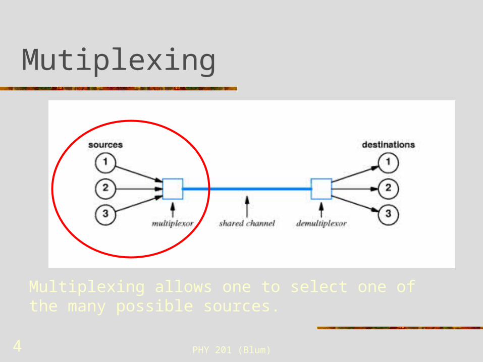
Multiplexing allows one to select one of the many possible sources.
PHY 201 (Blum) 5
Statistical TDM
In standard TDM, the inputs take turns, one after the other gets to put its information onto the wire.
In Statistical TDM, the input with the most data or highest priority gets a higher share of the time.
In this course, our wires hold a single bit of information at a time, so we will focus on a simple type of TDM. It will be somewhat more like statistical TDM in that we will be choosing which input places its information on the wire.
PHY 201 (Blum) 6
Multiplexing
There are several data inputs and one of them is routed to the output (possibly the shared communication channel). Like selecting a television channel (although that
example is FDM). In addition to data inputs, there must be select
inputs. The select inputs determine which data input gets
through. How many select pins are needed?
Depends on number of data inputs.

PHY 201 (Blum) 7
Addresses
All of the (data) inputs at hand are assigned addresses. The address of the data input is used to select which data input is placed on the shared channel.
So in addition to the collection of data inputs, there are selection (or address) inputs that pick which of the data inputs gets through.

PHY 201 (Blum) 8
How many?
One bit can have two states and thus distinguish between two things.
Two bits can be in four states and … Three bits can be in eight states, … N bits can be in 2N states
0 0 0
0 0 1
0 1 0
0 1 1
1 0 0
1 0 1
1 1 0
1 1 1
PHY 201 (Blum) 9
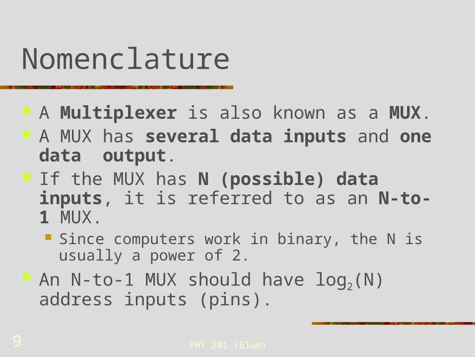
Nomenclature
A Multiplexer is also known as a MUX. A MUX has several data inputs and one data
output. If the MUX has N (possible) data inputs, it is
referred to as an N-to-1 MUX. Since computers work in binary, the N is usually a power
of 2. An N-to-1 MUX should have log2(N) address inputs
(pins).
PHY 201 (Blum) 10
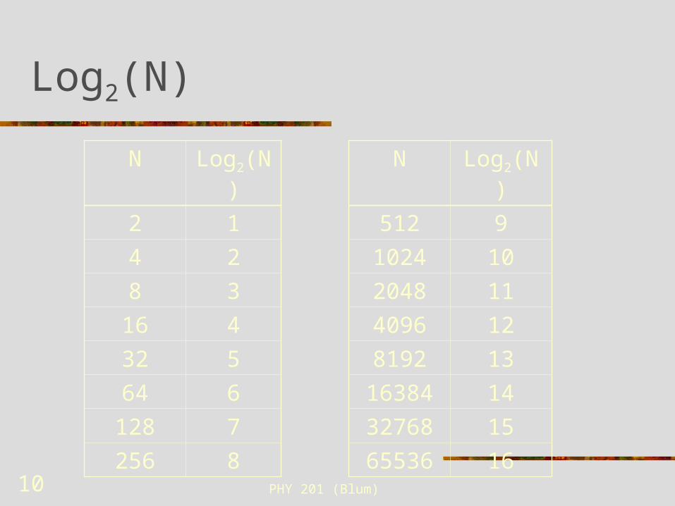
Log2(N)
N Log2(N)
2 1
4 2
8 3
16 4
32 5
64 6
128 7
256 8
N Log2(N)
512 9
1024 10
2048 11
4096 12
8192 13
16384 14
32768 15
65536 16
PHY 201 (Blum) 11
Combinatorial Logic
A MUX uses combinatorial logic (as opposed to a sequential logic which involves memory).
The output of a MUX depends solely on the data input and the select input.
Thus it is just the realization of a truth table.

PHY 201 (Blum) 12
Truth table for 2-to-1 MUX
Select Data
OutA D0 D1
0 0 0 0
0 0 1 0
0 1 0 1
0 1 1 1
1 0 0 0
1 0 1 1
1 1 0 0
1 1 1 1
When A=0, Out is same as D0, when A=1, Out is same as D1
PHY 201 (Blum) 13
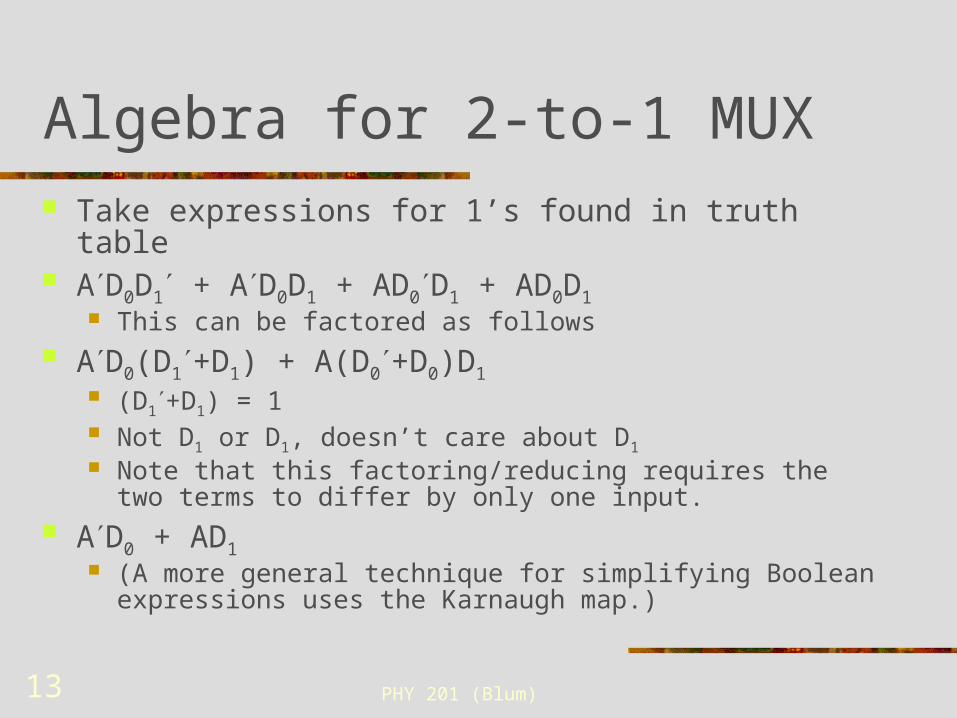
Algebra for 2-to-1 MUX Take expressions for 1’s found in truth table AD0D1 + AD0D1 + AD0D1 + AD0D1
This can be factored as follows AD0(D1+D1) + A(D0+D0)D1
(D1+D1) = 1 Not D1 or D1, doesn’t care about D1
Note that this factoring/reducing requires the two terms to differ by only one input.
AD0 + AD1 (A more general technique for simplifying Boolean expressions uses
the Karnaugh map.)
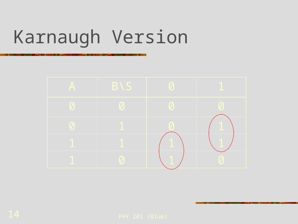
PHY 201 (Blum) 14
Karnaugh Version
A B\S 0 1
0 0 0 0
0 1 0 1
1 1 1 1
1 0 1 0

PHY 201 (Blum) 15
Gates for 2-to-1 MUX
V15 V
J1
Key = 0
J2
Key = 1
J5
Key = A
U1NOT
X1
2.5 V
U2
AND2
U3
AND2
U4
OR2
PHY 201 (Blum) 16
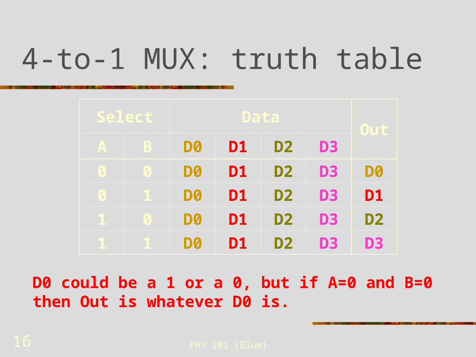
4-to-1 MUX: truth table
Select DataOut
A B D0 D1 D2 D3
0 0 D0 D1 D2 D3 D0
0 1 D0 D1 D2 D3 D1
1 0 D0 D1 D2 D3 D2
1 1 D0 D1 D2 D3 D3
D0 could be a 1 or a 0, but if A=0 and B=0 then Out is whatever D0 is.
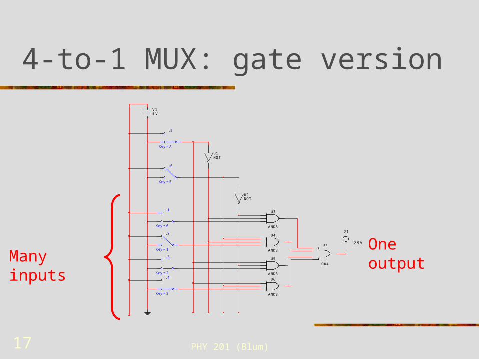
PHY 201 (Blum) 17
4-to-1 MUX: gate version
Many inputsOne output
V15 V
J1
Key = 0
J2
Key = 1
J3
Key = 2J4
Key = 3
J5
Key = A
J6
Key = B
U1NOT
U2NOT
U3
AND3
U4
AND3
U5
AND3
U6
AND3
U7
OR4
X1
2.5 V
PHY 201 (Blum) 18
Addresses
Each data input is assigned to a specific state of the select input. E.g. low-low, low-high, high-low, high-high
The state can be interpreted as binary numbers 00, 01, 10, 11 Two select Four addresses
And these numbers are thought of as the “addresses” of the input.

PHY 201 (Blum) 19
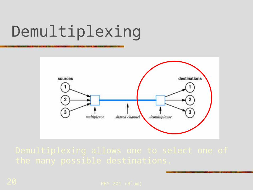
Demultiplexing
If any of several signals was put onto a single carrier, then at the other end the signals must be separated and each sent to the appropriate destination.
One input (the shared channel) is routed to one of several outputs. Like mail, it is possible for me to send a message to any
individual one of you. So there must be a set of paths from me to each of you, and there must be a mechanism for selecting one of those paths in a particular instance.
In addition to data input, there must be select inputs. To select from 2N data outputs requires N select inputs.
PHY 201 (Blum) 20
Demultiplexing
Demultiplexing allows one to select one of the many possible destinations.

PHY 201 (Blum) 21
Nomenclature Demultiplexer a.k.a. DeMUX. A DeMUX has one data input and several outputs.
If the DeMUX has N (possible) data outputs, it may referred to as an 1-to-N DeMUX.
Since computers work in binary, the N is usually a power of 2.
An 1-to-N DeMUX should have log2(N) address inputs (pins).
DeMUX are also sometimes referred to by the number of address pins log2(N)-to-N DeMUX (e.g. 3-to-8 or 2-to-4 DeMUX)

PHY 201 (Blum) 22
Combinatorial Logic
A DeMUX has many outputs. Each of those outputs depends only on the
input data and the select data (i.e. no memory is involved) .
Thus a DeMUX is just a realization of a truth table (as is all combinatorial logic).
PHY 201 (Blum) 23
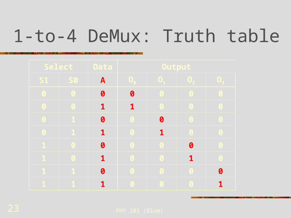
1-to-4 DeMux: Truth table
Select Data Output
S1 S0 A O0 O1 O2 O3
0 0 0 0 0 0 0
0 0 1 1 0 0 0
0 1 0 0 0 0 0
0 1 1 0 1 0 0
1 0 0 0 0 0 0
1 0 1 0 0 1 0
1 1 0 0 0 0 0
1 1 1 0 0 0 1
PHY 201 (Blum) 24
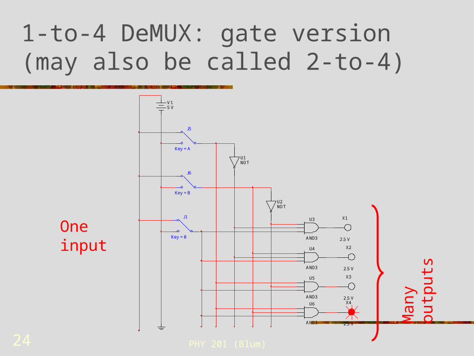
1-to-4 DeMUX: gate version (may also be called 2-to-4)
One input
Man
y ou
tput
s
V15 V
J1
Key = 0
J5
Key = A
J6
Key = B
U1NOT
U2NOT
U3
AND3
U4
AND3
U5
AND3
U6
AND3
X1
2.5 V
X2
2.5 V
X3
2.5 VX4
2.5 V
PHY 201 (Blum) 25
Decoder
A variation on the previous circuit is to have no input data.
The selected output will be high, the others low. Or vice versa.
This can be used to activate a control pin on the selected part of circuit.

PHY 201 (Blum) 26
2-to-4 Decode: Truth table
Select Output
S1 S0 O0 O1 O2 O3
0 0 1 0 0 0
0 1 0 1 0 0
1 0 0 0 1 0
1 1 0 0 0 1
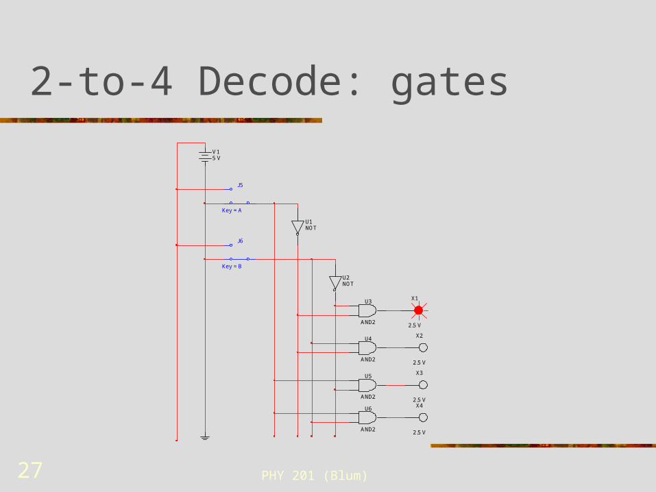
PHY 201 (Blum) 27
2-to-4 Decode: gates
V15 V
J5
Key = A
J6
Key = B
U1NOT
U2NOT
X1
2.5 V
X2
2.5 V
X3
2.5 VX4
2.5 V
U3
AND2
U4
AND2
U5
AND2
U6
AND2
PHY 201 (Blum) 28
Decoder plus registers = RAM
A register is a unit of memory that holds one word of data. A typical word may be 32 or 64 bits. E.g. the Memory Address Register (MAR) holds an
address associated with memory Memory (RAM), on the other hand, is a large
collection of registers to hold the values of many different words.
In addition to the registers is a decoder. The decode determines which word one is writing to or reading from.
PHY 201 (Blum) 29
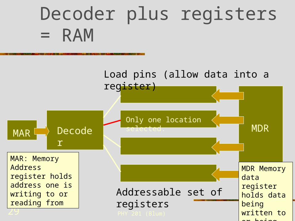
Decoder plus registers = RAM
Decoder
MDR
MAR
Load pins (allow data into a register)
Addressable set of registers
MAR: Memory Address register holds address one is writing to or reading from
MDR Memory data register holds data being written to or being read from memory.
Only one location selected.
PHY 201 (Blum) 30
ROM is Combinatorial
In ROM (Read Only Memory), one inputs an address and gets a predetermined output for that address.
The same input always yields the same output. ROM is the realization of a truth table. ROM is a way to realize a generic truth table.
In a way the opposite of what we do with a Karnaugh map. With a K-map we take a specific output and simplify it as much as possible. With ROM, we leave it as generic as possible.
PHY 201 (Blum) 31
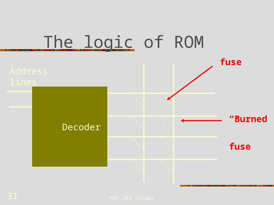
The logic of ROM
Decoder
Address lines
fuse
“Burned”
fuse

PHY 201 (Blum) 32
Logic of ROM (Cont.)
Fuses connect output of decoder to output of ROM.
Normal voltage and current does not burn (“blow”) the fuse.
So when the selected decoder output is high, all ROM output lines to which it is connected are also high.
PHY 201 (Blum) 33
Logic of ROM (Cont.)
Higher voltage and current will break the connections (a.k.a. burning).
They are applied selectively to break certain connections.
The ROM output is not affected by the decoder output if the connection is broken.
(Implementation may be different, but this is the basic logic).