Photographic Techniques for Information Storage
8
King, Brown, and Ridenour: Photographic Techniques for Information Storage problems in the realization of such memories are the switching and read-out methods by which fast random access can be obtained efficiently. Successful solutions to these problems are demonstrated in the experimental 10,000 bit memory reported in this paper. Last year, on the basis of a memory with 256 bits, we predicted2 that in the near future storage capacities of thousands or tens of thousands would be achieved and capacities of millions, in a more distant future. As the first part of this prediction is now realized we venture to reiterate the second. Of course, this will require great innovations in construction techniques and still further improvements in magnetic switching. But we have no doubt that memories in which random access to millions of information bits in a few microseconds will be available at a relatively low cost. This will usher in a new area in information handling systems which may have profound consequences, not only in scientific com- putations, but wherever complicated or repetitive com- putations burden our lives. ACKNOWLEDGMENT This project was brought to success by many mem- bers of the RCA Laboratories, principally R. Stuart- Williams"3 and M. Rosenberg"3 who made important original contributions. The essential ferrospinel ma- terials research work was done by I. J. Hegyi, R. S. Weisz and R. L. Harvey. Many of the attendant tests were made by T. Arbaeus, American-Scandinavian trainee at the Laboratories. J. Lehmann and S. Stern- berg designed many of the circuits and C. H. Vose the circuit lay-outs. A. Lo and W. Modlinski participated in initial measurements and M. Kaplan from RCA Victor Division did most of the final testing of the system. R. L. Hunyady wired the myriabit array, and J. Walen- tine contributed in the design and built the automatic core tester. The project had the constant supervising interests of V. K. Zworykin. 13 With International Telemeter Co. since May, 1953. Photographic Techniques for Information Storage * GILBERT W. KING, GEORGE W. BROWN, AND LOUIS N. RIDENOURt, SENIOR MEMBER, IRE Summary--Photographic media are examined as vehicles for the storage of digital information. Storage devices of total capacity in the range from 107 to 109 bits, with favorable random-access features, appear to be achievable. Alternative methods of reading are sug- gested. The logical association of a much smaller erasable storage unit (such as a magnetic drum) with a large photographic store com- pletely removes, for most practical applications, the difficulties arising from the fact that rapid erasure and rewriting are not possible in a photographic storage medium. Methods for writing in the information to be stored are briefly considered. I. INTRODUCTION HOTOGRAPHIC MEDIA suggest themselves as means of information storage for computers and other information-processing machines be- cause of the high density of information storage that available emulsions can yield. The resolving power of the best photographic emulsions is in excess of 103 marks per millimeter, corresponding to superficial in- formation densities of about 106 bits/mm2. Even when this number is reduced by practical considerations in- volving registration in the reading process, discrimina- tion against spurious signals arising from dust or scratches, etc., a very substantial information density remains. It has been appreciated for some time that all the information ever written in books could be stored in a few cubic yards of photographic plates, and equally * Decimal classification: 621.375.2. Original manuscript received by the Institute, June 1, 1953. t International Telemeter Corporation, Los Angeles, California; aided by the Office of Naval Research. well realized that such a library is impracticable because of the difficulty presented by suitable access to the stored information. The high information density offered by photographic storage has led to some work on its use in connection with computers. In 1947, Arthur W. Tyler' and R. D. O'Neal2 of the Eastman Kodak Company re- ported at a Harvard symposium the results of some pre- liminary work which they had done. The point of view motivating this work was rather different from that which is appropriate today. Tyler and O'Neal were concerned with the use of photographic storage as an input or an input-output device for high-speed digital computers. This led them to put major attention on strip film as the photographic medium, and the well known difficulties of registering film in a gate forced them to an excessive reduction of the information density actually used. In addition to difficulties of registration, the handling of strip film inevitably pro- duces degradation of the emulsion surface through scratches produced by the handling mechanism and dirt deposited on the film during handling. Because Tyler and O'Neal also wished to provide for random access to the information stored on the film, their film-handling apparatus had to provide for rapid starting, stopping and reversal. All in all, the ground 1 Arthur W. Tyler, Annals of the Computation Lab., Harvard Univ., vol. 16, p. 146; 1948. 2 R. D. O'Neal, Annals of the Computation Lab., Harvard Univ., vol. 16, p. 260; 1948. 1953 1421
Transcript of Photographic Techniques for Information Storage

King, Brown, and Ridenour: Photographic Techniques for Information Storage
problems in the realization of such memories are theswitching and read-out methods by which fast randomaccess can be obtained efficiently. Successful solutionsto these problems are demonstrated in the experimental10,000 bit memory reported in this paper.
Last year, on the basis of a memory with 256 bits, wepredicted2 that in the near future storage capacities ofthousands or tens of thousands would be achieved andcapacities of millions, in a more distant future. As thefirst part of this prediction is now realized we ventureto reiterate the second. Of course, this will requiregreat innovations in construction techniques and stillfurther improvements in magnetic switching. But wehave no doubt that memories in which random access tomillions of information bits in a few microseconds willbe available at a relatively low cost. This will usher in anew area in information handling systems which mayhave profound consequences, not only in scientific com-putations, but wherever complicated or repetitive com-putations burden our lives.
ACKNOWLEDGMENTThis project was brought to success by many mem-
bers of the RCA Laboratories, principally R. Stuart-Williams"3 and M. Rosenberg"3 who made importantoriginal contributions. The essential ferrospinel ma-terials research work was done by I. J. Hegyi, R. S.Weisz and R. L. Harvey. Many of the attendant testswere made by T. Arbaeus, American-Scandinaviantrainee at the Laboratories. J. Lehmann and S. Stern-berg designed many of the circuits and C. H. Vose thecircuit lay-outs. A. Lo and W. Modlinski participated ininitial measurements and M. Kaplan from RCA VictorDivision did most of the final testing of the system.R. L. Hunyady wired the myriabit array, and J. Walen-tine contributed in the design and built the automaticcore tester.The project had the constant supervising interests of
V. K. Zworykin.
13 With International Telemeter Co. since May, 1953.
Photographic Techniques for Information Storage *
GILBERT W. KING, GEORGE W. BROWN, AND LOUIS N. RIDENOURt, SENIOR MEMBER, IRE
Summary--Photographic media are examined as vehicles for thestorage of digital information. Storage devices of total capacity in therange from 107 to 109 bits, with favorable random-access features,appear to be achievable. Alternative methods of reading are sug-gested. The logical association of a much smaller erasable storageunit (such as a magnetic drum) with a large photographic store com-pletely removes, for most practical applications, the difficulties arisingfrom the fact that rapid erasure and rewriting are not possible in aphotographic storage medium. Methods for writing in the informationto be stored are briefly considered.
I. INTRODUCTIONHOTOGRAPHIC MEDIA suggest themselvesas means of information storage for computersand other information-processing machines be-
cause of the high density of information storage thatavailable emulsions can yield. The resolving power ofthe best photographic emulsions is in excess of 103marks per millimeter, corresponding to superficial in-formation densities of about 106 bits/mm2. Even whenthis number is reduced by practical considerations in-volving registration in the reading process, discrimina-tion against spurious signals arising from dust orscratches, etc., a very substantial information densityremains. It has been appreciated for some time that allthe information ever written in books could be stored ina few cubic yards of photographic plates, and equally
* Decimal classification: 621.375.2. Original manuscript receivedby the Institute, June 1, 1953.
t International Telemeter Corporation, Los Angeles, California;aided by the Office of Naval Research.
well realized that such a library is impracticable becauseof the difficulty presented by suitable access to thestored information.The high information density offered by photographic
storage has led to some work on its use in connectionwith computers. In 1947, Arthur W. Tyler' andR. D. O'Neal2 of the Eastman Kodak Company re-ported at a Harvard symposium the results of some pre-liminary work which they had done. The point of viewmotivating this work was rather different from thatwhich is appropriate today. Tyler and O'Neal wereconcerned with the use of photographic storage as aninput or an input-output device for high-speed digitalcomputers. This led them to put major attention onstrip film as the photographic medium, and the wellknown difficulties of registering film in a gate forcedthem to an excessive reduction of the informationdensity actually used. In addition to difficulties ofregistration, the handling of strip film inevitably pro-duces degradation of the emulsion surface throughscratches produced by the handling mechanism anddirt deposited on the film during handling.
Because Tyler and O'Neal also wished to provide forrandom access to the information stored on the film,their film-handling apparatus had to provide for rapidstarting, stopping and reversal. All in all, the ground
1 Arthur W. Tyler, Annals of the Computation Lab., HarvardUniv., vol. 16, p. 146; 1948.
2 R. D. O'Neal, Annals of the Computation Lab., Harvard Univ.,vol. 16, p. 260; 1948.
1953 1421

1422 PROCEEDINGS OF THE I.R.E.
rules adopted by Tyler and O'Neal at the outset of theirinvestigation were such as to eliminate or greatly de-grade the inherent advantages offered by film as amedium for storing information. It is therefore not re-markable that these authors appeared to prefer the useof phosphor-coated strips to the use of film for the ap-plication they had in mind.
It is our purpose in this paper to recognize at the out-set the capabilities and limitations offered by photo-graphic media, and to consider which applications ofthese media to information storage may best exploitthe unique capabilities of the photographic emulsion,while avoiding the more troublesome limitations asso-ciated with its use. It is apparent that ordinary photo-graphic media do not lend themselves well to applica-tions which require even moderately high speeds ofwriting, erasure or re-writing. The type of use that isappropriate to photographic media is then one char-acterized by the following conditions: (a) large quan-tities of information must be stored, (b) random accessto any item of the stored information is needed andmust be accomplished in a time which should be sub-stantially less than a second, and (c) the stored in-formation is either of permanent nature or else changesrather slowly. Fortunately, situations of this kind doexist. Indeed, it is one of the deficiencies of present in-formation-processing machines that the capacity of thelargest high-speed random-access storage systems nowavailable is limited to a few million bits. If more in-formation must be stored, then it is put on long mag-netic tapes or into decks of punched cards, with a cor-responding increase in the time required for randomaccess.
II. STORAGE DENSITY ACHIEVABLE
As already mentioned, suitable emulsions will storemarks and spaces representing digital information at amaximum information density in the neighborhood of106 bits/mm2. The linear density of information storageshould probably be reduced by an order of magnitudeor more in order to provide an adequate safeguardagainst difficulties of registration. This means that theresulting information density is in the range of 103 to104 bits/mm2. Depending upon the reading methodchosen, it may be necessary to diminish this densityfurther, but there is no necessity for reducing the in-formation density to 8/mm2 as suggested by Tyler andO'Neal, providing that the photographic medium ismounted on a backing which can be positioned moreaccurately and better reproduced than could the stripfilm they were considering.
Let us compare these figures for photographic mediawith current standards for magnetic recording. Engi-neering Research Associates, who have had extensiveexperience in the use of magnetic media for informationstorage, have standardized on 80 bits per inch (forreturn-to-zero recording) and use a track-to-track spac-ing of 1/16 inch. This yields an information density of
about 2 bits/mm2, between one and two orders of mag-nitude lower than that which can probably be realizedby the use of photographic media. It is important tonotice that the track-to-track spacing in magnetic re-cording is fixed at some rather large value, not by thedifficulties of mechanical registration (as in the case ofphotographic recording), but rather by the far morefundamental difficulty that there will be crosstalk be-tween adjacent channels if they are spaced too closely.There appears to be very little leeway remaining in thepresent standards of information-density for magneticrecording; in the case of photographic recording, themedium itself affords us several orders of magnitude ofpotential increase above the densities we are choosingto consider in this preliminary investigation. If we areclever enough, some of this potential increase in densitywill be realized through the development of improvedtechniques.Another point worth noting when magnetic recording
and photographic recording are compared concerns therate at which the stored information can be read out.There is no lower limit on the reading speed usingphotographic media. The upper limit is not set by themedium, but rather by the auxiliary electronic circuitsconcerned with reading and processing the stored in-formation. In the case of magnetic recording, on theother hand, a lower limit in reading speed is fixed by thefact that the signal is produced by changing flux in thereading head and therefore has a magnitude which, tothe first order, is proportional to the reading speed. Anupper limit to the reading speed is set, in the magneticcase, by various factors, of which the frequency re-sponse of the reading head is usually the most im-portant. The highest practicable information rate atwhich magnetic media can be read is now between oneand two times 105 bits/sec. Of course, there is no suchupper limit on the speed of reading information storedin *photographic media. This is a fortunate circum-stance, since a given speed of physical movement of thestorage surface past a reading "head" will yield an in-formation rate which is directly proportional to thelinear information density along the track being read.Since we are proposing to increase this linear informa-tion density by a factor between 10 and 100, a cor-responding change in the rate at which information isread will enable the storage medium to be moved atcomparable speeds in the two types of storage.A relatively small, but perhaps important, increase in
the density of information storage in photographicmedia may be achieved by the use of color photographyrather than black-and-white. With existing commercialthree-color emulsions, three bits of information can bestored in a single mark. Each reading station wouldinvolve color filters or dichroic mirrors to separate thethree bits stored at each spot.The reason three bits can be stored in the place of one
lies in the fact that there are three dyes and filtersknown which are orthogonal in the sense that the
1422 October

King, Brown, and Ridenour: Photographic Techniques for Information Storage
integral of the dye and filter functions over wavelengthis zero except for the three pairs. Clearly "n-color pho-tography" would increase the capacity by a factor n.
A large number of orthogonal filters can be made; e.g.,
the Billings type. It should be noticed that the de-mands of a digital photographic memory on the dye are
not as stringent as those of color photography, becausewe are not concerned with faithfulness of reproductionof shades, etc. In fact, one can anticipate relaxation ofthe definition of orthogonality, to the extent that whitelight through the many combinations of dyes and filtersmust not be greater than 10 per cent of the intensityobtained by the correct pairs. Electrical circuits couldreadily discriminate between these two levels of outputfrom the photocells.The number n is thus determined by the half-width
of the absorption spectrum of available dyes. It seems
that all types of dyes have a half-width of about1000 A, determined by the number of vibrational levelsin each electronic state. This number is large andabout the same for all organic dye molecules or in-organic crystals. Thus it would seem that the maxi-mum value of n is four, using visible light. Four-colorphotography would be very useful, either in pure binaryor mixed binary-decimal recording.
III. METHODS OF READINGThere appears then to be no difficulty in storing all
the information of immediate requirements in reason-
able areas. The real difficulty lies in scanning such areas
conveniently; and this is determined by the size of thefield measured in units of resolvable lines.
In order to read out the information stored in a
photographic medium we may either: (a) hold the emul-sion stationary and move the reading head, (b) move
the emulsion past a stationary reading head, or, (c)combine these two techniques in some suitable fashion.Examples of schemes involving each of these methodswill now be given.
A. Flying-Spot Scanner, Two Dimensions3
If the photographic storage medium is mounted on a
transparent backing, then the illumination of the stor-age surface by a fine spot of light whose position can beadjusted will be equivalent to moving a reading "head,"provided that the photosensitive device serving as a
pickup and its associated optical system are so ar-
ranged that the sensitive surface of the pickup elementcan be illuminated for any position of the scanning spot.This arrangement is exactly like that of a flying-spotscanner used in television broadcasting. A single flying-spot scanner can illuminate only as many stored bits ofinformation as the ratio between its limits of beammotion and the diameter of its spot will allow. Since the
F. Roberts and J. Z. Young, Proc. Inst. of Elec. Eng., vol. 99,series IIIA, no. 20, 1952; Nature, vol. 167, p. 231, 1951 and vol. 169,p. 963; 1953
image of the flying spot can be enlarged or condensedby optical means, the absolute spot diameter is unim-portant, but the number of distinguishable bits of in-formation will not be increased by such enlargement orreduction in the image of the flying spot.
Present-day cathode-ray tubes can resolve about 1000distinguishable spots over the distance corresponding toone full line of scan. This means that a stationary photo-graphic storage medium illuminated by a single flying-spot scanner can store, at most, about 106 bits ofinformation. If the information is read off the emulsionat a megacycle rate, one second would be required toscan the entire contents of the stationary storage sur-face. The size of the area storing the one megabit whichis accessible to a flying-spot scanner may be of any size.Since it is reasonable to photograph 30 lines/mm, ourmegabit could be stored in an area slightly greater thanone square inch. If the access time of one second permegabit were acceptable for some specific application,the storage capacity of this system could be extendedindefinitely by having many separate megabit "cards."All the advantages of sorting, collating, and coarserandom access which are peculiar to cards could thenbe obtained. Alternatively, the megabits could bephotographed in frames of strip film, and the advantagespeculiar to tape storage systems could be realized.The two-dimensional flying-spot scanner may not be
practical, because the registration of the flying spot onany particular digit or line of digits depends upon theprecision of control afforded by analogue devices pro-ducing the deflection voltages or currents. The problemis similar to that of constructing an address generatorfor the so-called Williams type of electrostatic storagesystem, but it is more difficult because 30 times asmany "addresses" need to be generated for each co-ordinate.
However, when the logic of the information indexingis such that location by single address is impossible,and a sequential search is demanded, the requirementson the analogue deflection circuits are far less stringentthan in the electrostatic storage system. It is relativelyeasy to start the spot off at the correct point, and by asuitable design of bit symbols and tracks, to keep thespot in the track by feedback systems. Examples ofsuch systems are given later. Moving from one track tothe next parallel one may be somewhat more difficult,and packing in this direction may have to be relaxedcorrespondingly.
B. Motion of the Emulsion Past a Stationary ReadsngHead
This reading scheme was the only one to be consideredby Tyler and O'Neal.2 They planned to have an opticalsystem which would have a field of view encompassingan array of several information-storage positions in thefocal plane of the reading system. Individual photocellswere to be mounted behind apertures in a suitablemask, each aperture in the mask corresponding to one
1953 1423

PROCEEDINGS OF THE I.R.E.
storage position on the photographic medium. At highinformation-densities in the medium, quite substantialmagnification would be needed to get from the size ofthe tiny storage positions to the size of a two-dimen-sional array of reading devices. The use of photo-transistors for reading enables the reading array to bemade more compact, but it is still true that a consider-able magnification is required.
However, there is no reason to suppose that a schemeof this sort would be impossible to realize. The mainobjection to it lies in the circumstance that the field ofthe reading head is only one bit, so that one must eitherprovide one head per information channel on the movingmedium (Tyler and O'Neal proposed to provide twoper channel in order to check on the accuracy of read-ing); or else one must move a reading head, containingone or a small number of reading stations, in a secularand very precise fashion from track to track. Neither ofthese schemes is very attractive. The difficulty of thefirst can be indicated by a simple computation. Let ussuppose that our photographic storage medium ismounted on the cylindrical surface of a drum 30 cmin diameter and that we have chosen a linear storagedensity of 30 bits/mm along any track. The total lengthof a single track will then be a little under 103 mm, andthe total information in a single track will amount to2.7 X 104 bits. To get a storage capacity of even a singlemegabit would require 36 tracks, each with its ownphotosensitive device, amplifier and associated circuitry.This is not a formidable requirement, but we havechosen a total storage capacity so low that it can bereached by magnetic storage devices. If we wish tostore 107 bits or 108 bits, we shall have to providehundreds or thousands of individual reading stations.Moving a single reading head or a gang of reading
heads from track to track along the drum may be usefulin some applications, but this also appears to offer con-siderable difficulties. For any reasonable number ofsingle reading heads ganged together, the access timefor a store of 10 to 100 megabits would become quitelong. Let us return to our earlier example. We saw that36 tracks were necessary to store a megabit, so that astore having a capacity of only 10 megabits would in-volve 360 tracks. At a megacycle reading rate the rota-tional speed of the drum in our example would amountto about 2100 rpm, a quite reasonable speed. However,to search 36 tracks at this speed (as would be requiredby a 10-station movable reading head) would take afull second. Further, a store of 10 megabits does notexhaust the storage capabilities of a drum of reasonablesize. Reasonably good machine work should permit thedevice transporting and registering the heads to indexsufficiently well so that neighboring tracks could beplaced on the surface of the drum at a spacing of 4per millimeter. The 360 tracks comprising a ten mega-bit store would occupy 90 mm, or less than 5 inches,along the cylindrical surface of a drum about a foot indiameter.
It seems clear that the information-storage capabil-ities of photographic emulsions lend themselves to ro-tating drums of reasonable dimensions containing atotal amount of information up to about 100 megabits.It seems equally clear that reading techniques derivedso directly from those useful in magnetic-drum tech-nology are far too slow to cope with the problem ofrapid access to a total quantity of stored informationof this size. New techniques better suited to the require-ments of the new storage medium must be devised.
C. Combination of the Flying-Spot Scanner with a MovingStorage SurfaceAs we saw earlier, a two-dimensional flying-spot scan-
ner viewing a stationary medium can distinguish onemegabit at most. To extend the amount of stored in-formation accessible to a single flying-spot scanner, weshall have to move the emulsion past the scanner. Itis now appropriate to restrict the flying-spot scanner tomotion in one dimension, which rather simplifies theproblem of locating the spot by analogue means. Wehave then a class of devices in which the scanning spotis moved along a line perpendicular to the direction ofmotion of the storage medium. Let us make some ele-mentary design considerations for a storage unit ofthis class. Consider a circular plate rotating about anaxis passing through its center and coated on one side orthe other with photographic emulsion. A flying-spotscanner can view the storage medium through a radialslit whose width is at our disposal. The use of such aslit eliminates the effects of spot size in the dimensionacross the slit. The information density along a track isthen fixed by the width of the slit, and not by the sizeof the spot. No such consideration applies in the direc-tion along the slit, however, so that we must have aspacing from track to track, and therefore a total num-ber of tracks, determined by the resolving power of thescanning spot, rather than by that of the photographicmedium. The resolving power of the scanning spot willbe fixed either by the ratio of spot excursion to spotdiameter, or else by the limits of reproducible control ofthe radial deflection of the spot. It is intended in thisarrangement that the light from the flying-spot scannerbe gathered by a suitable optical device and caused tofall on a single photoelectric reading head, independentof the position of the flying spot. Such an arrangementis shown schematically in Fig. 1, following page.
Let us make a few calculations regarding such a de-vice. Suppose that the disk is 50 cm in diameter andthat we use a slit 5 microns wide. Using a pair of marksto represent a bit and allowing a factor of two forsafety, this permits the storage of 50 bits/mm alongany track. The average track near the edge of the diskis about 1500 mm long, and would thus contain7.5 X 104 bits. Let us suppose that control of the radialdeflection in the flying-spot scanner permits us to dis-tinguish with certainty any one of 64 tracks; this is aslight extension of Williams-tube address-generator
1424 October

13King, Brown, and Ridenour: Photographic Techniques for Information Storage
FIELD LENS
ITATIN PLATE
Fig. 1-Flying spot scanning a rotating disk.
techniques now in common use. The disk storage devicedefined by these parameters would then have a totalcapacity of 4.8 megabits. The use of color wouldmultiply the storage capacity by 3, bringing it to 14.4megabits.
Reading through the entire stored information at amegacycle rate with a single head (or a single three-color head) would require nearly 5 seconds, so that thisdevice is most useful when it is employed in conjunc-tion with a sort of "index" which specifies the addressof the information wanted. Once this address is known,the flying-spot scanner can select the desired track in avery few microseconds. The rotational speed correspond-ing to a reading rate of one megabit per second is 13.3revolutions per second or 800 rpm. This is a reasonablespeed for a device of such size.The access time of a rotating store is determined by
the speed of rotation, which has to be kept below acritical value which, for glass, corresponds to about1000 ft/sec peripheral velocity. Parallel reading by anumber of independently controlled reading stationsaround the circumference of the disk, or duplication ofthe information on the disk, will diminish access timeand speed up the rate at which information can betaken from the store.
It appears that the major design difficulty presentedby a storage device in which the photographic mediummoves past a reading head may lie in minimizing themechanical irrgularities in the motion of the medium;these must produce a maximum displacement smallerthan the size of the bit symbol. Vibrations of the disk asa circular membrane will move the track out of theplane of focus, eccentricity of a track or radial vibra-tions will be troublesome, and angular vibrations or non-uniform rotational speed will interfere with bit identi-fication. Calculations of the expected performance of a81 glass plate rotated on air bearings make it appearthat no difficulties of these sorts will be experienced.
D. High-Capacity Storage Unit with Integral IndexIn a large class of practical information-storage ap-
plications (directories, dictionaries, catalogues, etc.), the
stored information is accompanied by a much more com-pact index. This index is often integral with the storedinformation, as for example in a dictionary, where thewords beginning and ending each page are entered atthe top of that page.The inspection of such an index is governed by the
fact that the index is not a dense set of all binarynumbers having a given number of digits. Instead, theindex is usually highly redundant in having many moredigits (say n) than are necessary to describe the num-ber of items N<K2n. Thus a given "address" will notserve to direct the reading head to the proper locationin the index; rather, the index must be scanned in anextensive, if not exhaustive, fashion.We have already noticed that storage systems hav-
ing total capacities in the 10 to 100 megabit range can-not be completely read in microsecond time intervals(which are often wanted), even at the rates of readingin the megabit-per-second range permitted by photo-graphic storage, without requiring an undesirably largenumber of individual reading heads. In many problemswhich demand storage systems of this size, fortunately,it is possible to provide a greatly condensed index whichcan be scanned in order to determine the location of theinformation that it is desired to read in detail. A wellknown example of precisely this (and, incidentally, oneinvolving a photographic storage medium) is VannevarBush's Rapid Selector. Documents are photographed onmicrofilm and beside the image of each document oneach microfilm is placed a digital code-group identifyingthe contents of the frame. The reel of film containing theframes is then run through a reader which reads onlythe index information; when an index entry of interestappears, the information stored in the correspondingframe is photographed onto a fresh film by techniquesof flash photography. A complete search through allthe index entries contained in a reel then results in pro-ducing a new reel of film containing only those frameswhose information is of interest in connection with thesubject of the search.A philosophically similar technique appears to be
possible using the combination of flying-spot scanner
CATHODEYI=U
14251953
PROCEEDINGS OF THE I.R.E.
and rotating storage medium which we have beenconsidering. Suppose that the information stored onthe periphery of a photographic drum is laid down,not in a number of circular channels parallel to oneanother, but instead in a series of lines which runparallel to one another and nearly parallel to a generatorof the surface of the cylinder (Fig. 2). The angle be-tween one of these lines of information and the gen-erator will be the angle whose tangent is the ratio ofthe peripheral speed of the cylinder to the linear speedof the flying spot. Thus, when the flying spot scans alongthe axis of the cylinder at its standard rate, it will fol-low along one of these tracks on the surface of the drum.When the tracks are packed as closely together as theresolving power of the flying-spot scanner will allow,the time required for the execution of a scan along onetrack and the return of the spot to its starting positionwould be sufficiently long so that adjacent tracks couldnot be scanned in the same rotation of the drum. Letus make some preliminary design considerations toshow this.
SCANNING SNO AFOR ADDRESSSCNEONIGA
__
-
__
_ _
__
__
_ _
_.t_ _
ADDRESS 112
1-, - - /I
-
"-
XINFORMATION
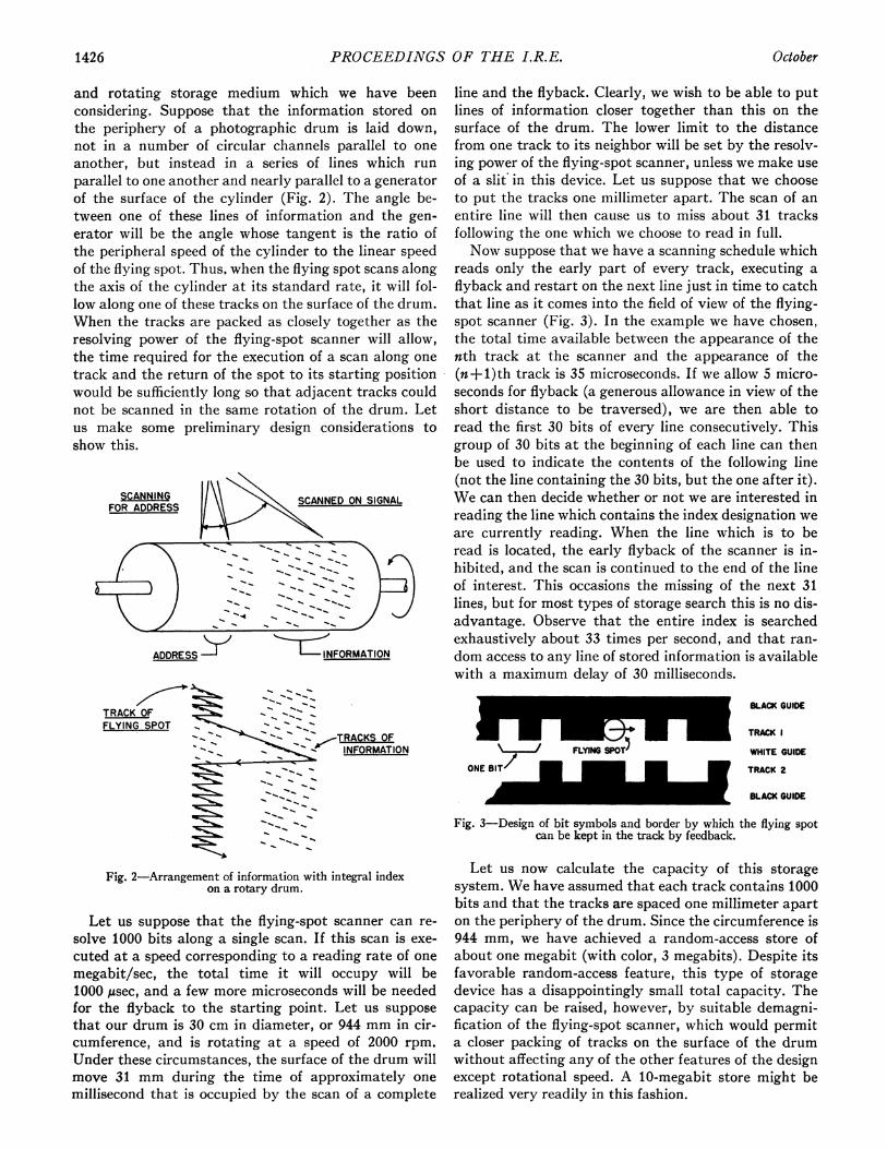
line and the flyback. Clearly, we wish to be able to putlines of information closer together than this on thesurface of the drum. The lower limit to the distancefrom one track to its neighbor will be set by the resolv-ing power of the flying-spot scanner, unless we make useof a slit in this device. Let us suppose that we chooseto put the tracks one millimeter apart. The scan of anentire line will then cause us to miss about 31 tracksfollowing the one which we choose to read in full.Now suppose that we have a scanning schedule which
reads only the early part of every track, executing aflyback and restart on the next line just in time to catchthat line as it comes into the field of view of the flying-spot scanner (Fig. 3). In the example we have chosen,the total time available between the appearance of thenth track at the scanner and the appearance of the(n+l)th track is 35 microseconds. If we allow 5 micro-seconds for flyback (a generous allowance in view of theshort distance to be traversed), we are then able toread the first 30 bits of every line consecutively. Thisgroup of 30 bits at the beginning of each line can thenbe used to indicate the contents of the following line(not the line containing the 30 bits, but the one after it).We can then decide whether or not we are interested inreading the line which contains the index designation weare currently reading. When the line which is to beread is located, the early flyback of the scanner is in-hibited, and the scan is continued to the end of the lineof interest. This occasions the missing of the next 31lines, but for most types of storage search this is no dis-advantage. Observe that the entire index is searchedexhaustively about 33 times per second, and that ran-dom access to any line of stored information is availablewith a maximum delay of 30 milliseconds.
TRACK OFFLYING SPOT OF
-.-,,TRACKS OFINFORMATION
Fig. 2-Arrangement of information with integral indexon a rotary drum.
Let us suppose that the flying-spot scanner can re-solve 1000 bits along a single scan. If this scan is exe-cuted at a speed corresponding to a reading rate of onemegabit/sec, the total time it will occupy will be1000 Asec, and a few more microseconds will be neededfor the flyback to the starting point. Let us supposethat our drum is 30 cm in diameter, or 944 mm in cir-cumference, and is rotating at a speed of 2000 rpm.Under these circumstances, the surface of the drum willmove 31 mm during the time of approximately onemillisecond that is occupied by the scan of a complete
BLACK GUIDE
TRACK I
WHITE GUIDE
TRACK 2ONE BIT/ I
Id I BLACK GUIDE
Fig. 3-Design of bit symbols and border by which the flying spotcan be kept in the track by feedback.
Let us now calculate the capacity of this storagesystem. We have assumed that each track contains 1000bits and that the tracks are spaced one millimeter aparton the periphery of the drum. Since the circumference is944 mm, we have achieved a random-access store ofabout one megabit (with color, 3 megabits). Despite itsfavorable random-access feature, this type of storagedevice has a disappointingly small total capacity. Thecapacity can be raised, however, by suitable demagni-fication of the flying-spot scanner, which would permita closer packing of tracks on the surface of the drumwithout affecting any of the other features of the designexcept rotational speed. A 10-megabit store might berealized very readily in this fashion.
, _ _ _
1426 October

King, Brown, and Ridenour: Photographic Techniques for Information Storage
If larger total storage capacities are wanted, onedrum of the type described might be used as an indexdrum capable of choosing among a multiplicity of stor-age drums or disks associated with it, and in the caseof the chosen storage drum indicating the track con-taining the information of interest. The storage devicescontrolled by such an index drum might be of the gen-eral sort described above under Section III-C.The primary limitation on the storage capacity at-
tainable by this scheme lies in the spacing necessaryfrom one track to its neighbor on the surface of thedrum. It may be possible to achieve closer spacings ifcurve-follower techniques are used to cause the spot tofollow the line it has commenced to scan. This mightbe done, for example, by a scheme of the following sort(see Fig. 3). Let us suppose that each bit recorded occu-pies the space which considerations of over-all systemresolving power would assign to a pair of distinguishablemarks. The digit zero could then be represented byblack followed by white, and the digit one by whitefollowed by black. Digits would be recognized by the"non-return-to-zero" technique often used in magneticrecording. On the average, each bit would be grey. Ifthere is now a white border at the top of the track anda black border at the bottom, then wandering of thespot away from the track would be attended by asecular increase or decrease in the average level oftransmitted light. The sense of the deflection correctionrequired to bring the spot back to the center of thetrack would be indicated by the sense of this change inlight travel. Filling the spaces between neighboringtracks with alternate black and white strips would re-quire an inversion of the sense convention between eachtrack and its neighbor; this should provide a valuablecheck on the fact that no track has been missed. Thefact that when the spot is in the track there is a strongsignal at twice the bit frequency might also be used asan additional means of control. It is clear that a self-tracking scheme of the sort described could also be usedin color emulsions.
In order to keep sufficiently square in shape the pulsesthat are produced in reading, the minimum size of thebit symbol should be between 10 and 100 times thelimiting resolving power of the photographic mediumused. This suggests that fine structure purposely intro-duced into the bit symbol could be used to improve re-liability: for example, by distinguishing a written zerofrom the lack of information, by distinguishing genuinesymbols from the effects of dust and scratches, etc.Alternatively, fine structure of the bit symbol mightenable the use of a ternary- or higher-base set of sym-bols. In this last connection, the exploitation of thegrey scale of a photographic emulsion might be con-sidered. In general, it is not advisable to use an analogueproperty such as this for the representation of digits,but the latitude afforded by silver-halide emulsionsmight be wide enough to permit two or more grey levelsto be reliably distinguished. Even if this could not be
done, the grey scale of the photographic medium mightbe used as a check against error.
IV. COMBINATION OF PHOTOGRAPHICAND MAGNETIC STORAGE
So far in this discussion, we have ignored the circum-stance that the writing of information into photo-graphic media is at best a slow process, involving, as itdoes, the exposure of the emulsion and subsequent chem-ical development and fixing. When the informationthat is to be stored in the drum is of a permanent char-acter, this is no great disadvantage, for a complete fileof the stored information can be produced once for allin photographic form. In many practical applicationsdemanding large-capacity rapid-access information stor-age, however, it is necessary to make periodic altera-tions in the stored information. Sometimes the informa-tion which is to be stored can be divided into two partson the basis of its permanence. In a machine designedto keep inventory records, for example, the designationsof the items comprising the inventory are either perma-nent or else change very slowly; the information repre-senting these catalog descriptions is thus suitable forstorage on photographic media. The quantity in stockof each item is altered whenever items are drawn fromor added to stock. The numbers representing thesequantities will therefore change far too rapidly to en-able them to recorded on photographic storage media.
In an application such as that of the inventorymachine just mentioned, we notice that the informa-tion describing the items ini' stock is usually severaltimes as voluminous as the information specifying howmany items of each sort are on hand. The former in-formation is permanent or quasi-permanent; the latteris subject to change. This is clearly a case which canbe dealt with by associating a photographic storagesystem with a magnetic store of smaller capacity. De-scriptions of items can be carried in the photographicstore, together with an address for each item whichspecifies the location on the magnetic drum at which isstored information regarding the quantity on hand ofthe item in question. Since the magnetic storage systemlends itself to rapid erasure and re-writing, the numbersspecifying the quantities in stock can be altered asrapidly as desired; since the catalog descriptions of theitems stocked do not alter over any reasonable periodof time, they can be carried in the more permanentphotographic storage.There is at least one other situation which requires
associating a magnetic storage system with a photo-graphic one. We noted that the catalog description ofthe items carried in the inventory machine is subjectto some change, even though this change is slow. If ithappens that changes in the catalog occur at intervalsmore frequent than those which justify the preparationof a new photographic surface containing new informa-tion, then we can make use of the following arrange-ment. We can associate with the photographic storage
1953 1427

1PROCEEDINGS OF THE I.R.E.
system (in addition to the magnetic drum which car-ries information on quantities in stock) another mag-netic drum on which we record the new or altered cata-log descriptions which have come along since the lastedition of the photographic store was prepared. Anycatalog reference demanded of this combined storagesystem will then be routed first through the magneticdrum containing the new or altered catalog informa-tion. If the item in question is represented by an entryon this magnetic drum, then the address of the quantitydesignation on the other magnetic drum will be securedfrom this first magnetic drum. If no entry regardingthe item in question is found in the magnetic drumbearing the catalog addenda, then the inquiry is routedon to the photographic store in order to find the addressof the storage location bearing information on stock inhand.
It is clear that the logical association of a necessarilysmaller magnetic storage system with a very largephotographic store will remove much of the limitationthat is occasioned by the difficulty of writing anderasure in photographic media. Other practical applica-tions of this technique of dual storage are very numer-ous, including, for example, that of maintaining areservation-file machine for a public carrier such as anairline or a railroad.
V. WRITING INFORMATION INTO
A PHOTOGRAPHIC STORE
The preparation of a photographic emulsion bearingdigital information is admittedly a slow process; forthis reason, the demands of speed placed on the writingapparatus need not be severe. However, a large numberof marks must be entered on the emulsion in a controlledfashion. Presumably, a human operator will originatethrough a manual process all of the information that itis desired to store. It is therefore appropriate to recordthe information on punched cards as the first step in thewriting process. Once this is done, conversion of theprimary information to binary form and its rearrange-
ment into the geometrical sequences desired for record-ing in the photographic store can be accomplishedmechanically at reasonably high speed through the useof standard punched-card equipment.The actual preparation of the photographic store is
similar to, but less exacting than, the photographicpreparation of reticles, an art which is highly advanced.Geiser,4 for example, describes the preparation of acircular track 440 mm long containing 8192 binarysymbols. This density of 18 lines/mm is below thatcontemplated in the present paper, but there appears tobe no limitation in writing technique or in emulsionresolving power which would prevent an increase ofone order of magnitude in linear storage density.
In many applications, the fact that contact printingwill enable the duplication of photographically storedinformation is of great value.
VI. CONCLUSIONSIt seems apparent, even on the basis of the rather
superficial consideration we have given to the use ofphotographic media for information storage, that theproper exploitation of photographic techniques shouldyield useful storage systems having total capacities inthe range from 10 to 1000 megabits of information. Withproper schemes for indexing, it should be possible togain random access to any entry in such a store in atime comparable to that which is needed to look up arandom address on the sort of magnetic drum that is incommon use today. There seems little doubt that thesepotential capabilities of photographic storage, whenfully realized by further research and development, willput into our hands a new type of device. The absence ofsuch a device is now severely limiting the application ofmodern computing and information processing tech-niques to practical non-numerical problems, as thoseencountered in the large scale clerical work of businessand the industrial control of industry.
4 Ralph D. Geiser, Photo. Eng., vol. 4, p. 1; 1953.
c7...A.5D
1428 October