pH/mV Temperature Meter Model 3510 - Scientific …1).pdf · 7 Section 1 Introduction 1.1...
36
Instruction Manual 351 050/REV C/02-17 pH/mV Temperature Meter Model 3510
Transcript of pH/mV Temperature Meter Model 3510 - Scientific …1).pdf · 7 Section 1 Introduction 1.1...
Instruction Manual351 050/REV C/02-17
pH/mV Temperature MeterModel 3510


3
Safety
Please read this information carefully prior to installing or using this equipment.
1. The unit described in this manual is designed be operated only by trained personnel. Any
adjustments, maintenance and repair must be carried out as defined in this manual, by a
person qualified to be aware of the hazards involved.
2. It is essential that both operating and service personnel employ a safe system of work, in
addition to the detailed instructions specified in this manual.
3. Other than for those items defined in the maintenance procedures herein there are no
user serviceable items in this instrument. Removal of covers and attempted adjustment or
service by unqualified personnel will invalidate the warranty and may incur additional
charges for repair.
4. References should always be made to the Health and Safety data supplied with any
chemicals used. Generally accepted laboratory procedures for safe handling of chemicals
should be employed.
5. If it is suspected that safety protection has been impaired in any way, the unit must be
made inoperative and secured against any intended operation. The fault condition should
immediately be reported to the appropriate servicing authority.
Merci de lire attentivement ces informations avant d'installer ou d'utiliser cet appareil.
1. L'appareil décrit dans ce manuel est conçu pour être utilisé uniquement par des
personnes formées. Tout réglage, maintenance ou réparation doit être effectué comme
décrit dans ce manuel, par une personne qualifiée consciente des risques encourus.
2. Il est essentiel que les personnes utilisant et intervenant sur cet appareil respectent les
règles de sécurité de travail, en plus des instructions détaillées précisées dans ce
manuel.
3. En-dehors des éléments décrits dans les procédures de maintenance ci-incluses, cet
appareil ne contient aucun élément réparable par l'utilisateur. L'enlèvement des capots et
les tentatives de réglage ou de réparation par des personnes non qualifiées invalide toute
garantie et entraîne un risque de frais de réparation supplémentaires.
4. Toujours se référer aux fiches techniques de santé et de sécurité accompagnant tout
produit chimique utilisé. Respecter les procédures de laboratoire généralement
acceptées pour la manipulation en toute sécurité des produits chimiques.
5. Si l'utilisateur suspecte qu'un problème quelconque puisse mettre en cause la sécurité,
l’appareil doit être rendu inopérant en empêchant son utilisation. Communiquer la
défaillance constatée au service de maintenance compétent.
4
Bitte lesen Sie diese Hinweise vor Installation oder Gebrauch dieser Ausrüstung sorgfältig
durch.
1. Das in diesem Handbuch beschriebene Gerät darf nur von geschultem Personal bedient
werden. Alle Anpassungen, Wartungsarbeiten und Reparaturen müssen entsprechend
der Vorgaben in diesem Handbuch und von einer kompetenten Person, die mit den damit
verbundenen Gefahren vertraut ist, durchgeführt werden.
2. Es ist wichtig, dass sowohl das Bedienungs- als auch das Service-Personal zusätzlich zu
den detaillierten Anweisungen in diesem Handbuch ein sicheres Arbeitssystem
einsetzen.
3. Mit Ausnahme der Teile, deren Wartungsverfahren in diesem Handbuch beschrieben
sind, enthält dieses Gerät keine weiteren Teile, die vom Benutzer gewartet werden
können. Das Entfernen von Abdeckungen und Versuche von hierfür unqualifiziertem
Personal, Anpassungen oder Wartungsarbeiten durchzuführen, haben zur Folge, dass
die Garantie verfällt und können zusätzliche Reparaturkosten auslösen.
4. Es ist jederzeit auf die sicherheitsrelevanten Daten sämtlicher verwendeter Chemikalien
Bezug zu nehmen. Allgemein anerkannte Labormethoden zum sicheren Umgang mit
Chemikalien sollten eingesetzt werden.
5. Besteht der Verdacht, dass die Sicherheitsvorrichtungen in irgendeiner Weise beschädigt
wurden, muss das Gerät außer Betrieb genommen und gegen weiteren Gebrauch
gesichert werden. Die Störung sollte der zuständigen Serviceeinrichtung unverzüglich
gemeldet werden.
Leggere attentamente queste istruzioni prima di installare o utilizzare il dispositivo.
1. L'unità descritta nel presente manuale è stata realizzata per essere utilizzata solo da
personale che ha ricevuto l'apposita formazione. Qualsiasi operazione di regolazione,
manutenzione e riparazione deve essere effettuata sulla base di quanto indicato nel
presente manuale da personale qualificato consapevole dei rischi connessi.
2. È fondamentale che il personale operativo e il personale addetto alla manutenzione
utilizzino un sistema di lavoro sicuro, oltre a seguire le istruzioni specificate nel presente
manuale.
3. Oltre a quelli indicati nelle procedure di manutenzione, all'interno di questo dispositivo
non sono presenti altri elementi sui quali è possibile effettuare interventi. La rimozione
delle protezioni e qualsiasi tentativo di regolazione o di manutenzione posto in essere da
personale non qualificato invaliderà la garanzia. In questi casi, sarà necessario pagare un
importo per le riparazioni effettuate.
4. È sempre necessario fare riferimento ai dati sulla salute e sulla sicurezza forniti con le
sostanze chimiche utilizzate. Adottare le procedure di laboratorio generalmente accettate
per la gestione delle sostanze chimiche.

5
5. Nel caso in cui si sospetti che la salute possa essere pregiudicata in qualsiasi modo,
disattivare l'unità per renderla inutilizzabile. Qualsiasi condizione di errore deve essere
immediatamente segnalata al responsabile per la manutenzione.
Lea esta información atentamente antes de instalar o utilizar este equipo.
1. La unidad descrita en este manual está diseñada para que solamente la utilice personal
con formación. Cualquier operación de ajuste, mantenimiento y reparación debe llevarse
a cabo del modo indicado en este manual y debe realizarla una persona cualificada que
sea consciente de los peligros que implica.
2. Es fundamental que tanto los operarios como el personal de servicio utilicen un sistema
de trabajo seguro, así como las instrucciones detalladas que se especifican en este
manual.
3. Cualquier elemento que no se encuentre entre los definidos en los procedimientos de
mantenimiento aquí descritos no podrá utilizarse en este instrumento. La extracción de
las tapas y los intentos de ajuste o reparación por parte de personal no cualificado
invalidarán la garantía y pueden incurrir en cargos adicionales por reparación.
4. Siempre deberían consultarse los datos sobre Salud y Seguridad que se suministran con
cualquier producto químico que se utilice. Es necesario llevar a cabo los procedimientos
de laboratorio de aceptación generalizada para la manipulación segura de productos
químicos.
5. Si existe la sospecha de que las medidas protectoras de seguridad han quedado
dañadas en cualquier modo, la unidad debe inutilizarse y protegerse contra toda
operación que se intente llevar a cabo. El estado de fallo debe comunicarse
inmediatamente a la autoridad de servicio de mantenimiento y reparación pertinente.

Model 3510pH/mV/Temperature Meter
Operating Manual
Contents
Section 1 IntroductionInstrument Description 1.1Instrument Specification 1.2
Section 2 InstallationUnpacking 2.1Installation 2.2Displays 2.3Keypad 2.4Inputs/Outputs 2.5
Section 3 OperationTheory of pH measurement 3.1pH Measurement 3.2Preparation of Buffer Solution 3.3Solution Temperature Values 3.4Good Practice Guidelines 3.5Instrument Set-Up 3.6pH Calibration 3.7Error Codes 3.8mV Mode 3.9Performing Measurements 3.10Results Storage and Display 3.11
Section 4 MaintenanceGeneral 4.1Cleaning/Re-conditioning of Glass Electrodes 4.2
Section 5 Optional AccessoriesOptional Accessories 5.1Spares 5.2
Section 6 InterfacingAnalogue 6.1RS232 6.2Keypad Emulation 6.3Printing 6.4
Section 7 TroubleshootingTroubleshooting 7.1Functional checks 7.2
EC Declaration of Conformity
351 050/REV B/09-06
6

7
Section 1
Introduction
1.1 Instrument Description
The Model 3510 is a general purpose pH/mV/Temperature bench meter used for routine laboratoryanalysis. The meter supports 1, 2 or 3 point pH calibration on either manually entered pH buffervalues or automatically temperature compensated buffers to DIN, JIS and NIST standards andJenway buffers supplied with the instrument. Up to 3 decimal place resolution is available. The 3510includes a 32 reading memory facility.
1.2 Instrument Specification
pH (1, 2 or 3 point cal)Range: -2.000 to 19.999pHResolution: 0.001 / 0.01 / 0.1pHAccuracy: ±0.003pH
mV (Absolute or Relative)Range: -1999 to +1999mVResolution: 0.1mVAccuracy: ±0.2mVInput Impedance: >1012ohms
Temperature MeasuringRanges: -10 to +105°C / 14 to 221°FResolution: 0.1°C / 1°FAccuracy: ±0.5°C / ±1°F
ATC Range: 0 to 100°C / 32 to 212°FManual Temp. Compensation: 0 to 100°C / 32 to 212°F
Auto Buffer Selection: Jenway (2.00, 4.00, 7.00, 9.20 and 10.00)DIN (3.06, 4.65, 6.79, 9.23, 12.75)NIST (1.68, 4.01, 6.87, 9.18, 12.45)JIS (1.68, 4.01, 6.87, 9.18, 12.45) or manually entered buffers
Calibration: User selectable 1, 2 or 3 pointOutputs: Analogue 1mV per 0.01pH
RS232Display: Back lit custom LCDPower: Power Supply 9VacSize: 275(l)x240(w)x150(d)mmWeight: 850g
351 050/REV B/09-061
8
351 050/REV B/09-062
Section 2
Installation
2.1 Unpacking
Remove the Model 3510 from the packaging and ensure the following items are included:
1. Model 3510 pH/mV/Temperature Meter2. Glass bodied combination pH electrode (924 005)3. ATC probe (027 500)4. Electrode holder5. 4, 7 and 10pH buffer sachets6. BNC shorting plug (009 146)7. Power Supply (as specified at time of ordering the product)8. Condensed operating instructions (351 051)9. Operating Manual (351 050)
Any shortages or damage should be reported immediately to the manufacturer or your localdistributor.
2.2 Installation
The Model 3510 is supplied ready to use. Connect the ATC (if required) and the pH electrode to therear panel Temp and pH sockets.
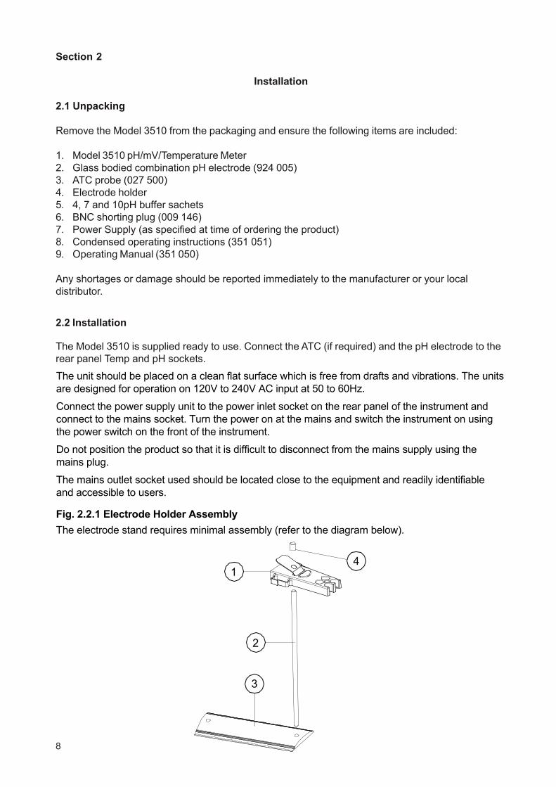
The electrode stand requires minimal assembly (refer to the diagram below).
Fig. 2.2.1 Electrode Holder Assembly
41
2
3
8
Section 2
Installation
2.1 UnpackingRemove the Model 3520 from the packaging and ensure the following items are included:
1. Model 3520 pH/mV/Temperature Meter2. Glass bodied combination pH electrode (924 005)3. ATC probe (027 500)4. Electrode holder (903 300)5. 4, 7 and 10pH buffer sachets6. BNC shorting plug (009 146)7. Power Supply (as specified at time of ordering the product)8. Condensed operating instructions (352 051)9. Operating Manual (352 050)
4
Any shortages or damage should be reported immediately to the manufacturer or your local distributor.
2.2 Installation
The Model 3520 is supplied ready to use. Connect the ATC (if required) and the pH electrode to the rear panel Temp and pH sockets.
The unit should be placed on a clean flat surface which is free from drafts and vibrations. The units are designed for operation on 120V to 240V AC input at 50 to 60Hz.
Connect the power supply unit to the power inlet socket on the rear panel of the instrument and connect to the mains socket. Turn the power on at the mains and switch the instrument on using the power switch on the front of the instrument.
Do not position the product so that it is difficult to disconnect from the mains supply using the mains plug.
The mains outlet socket used should be located close to the equipment and readily identifiable and accessible to users.
Fig. 2.2.1 Electrode Holder AssemblyThe electrode stand requires minimal assembly (refer to the diagram below).
1
2
3
9
351 050/REV B/09-063
2.3 Display
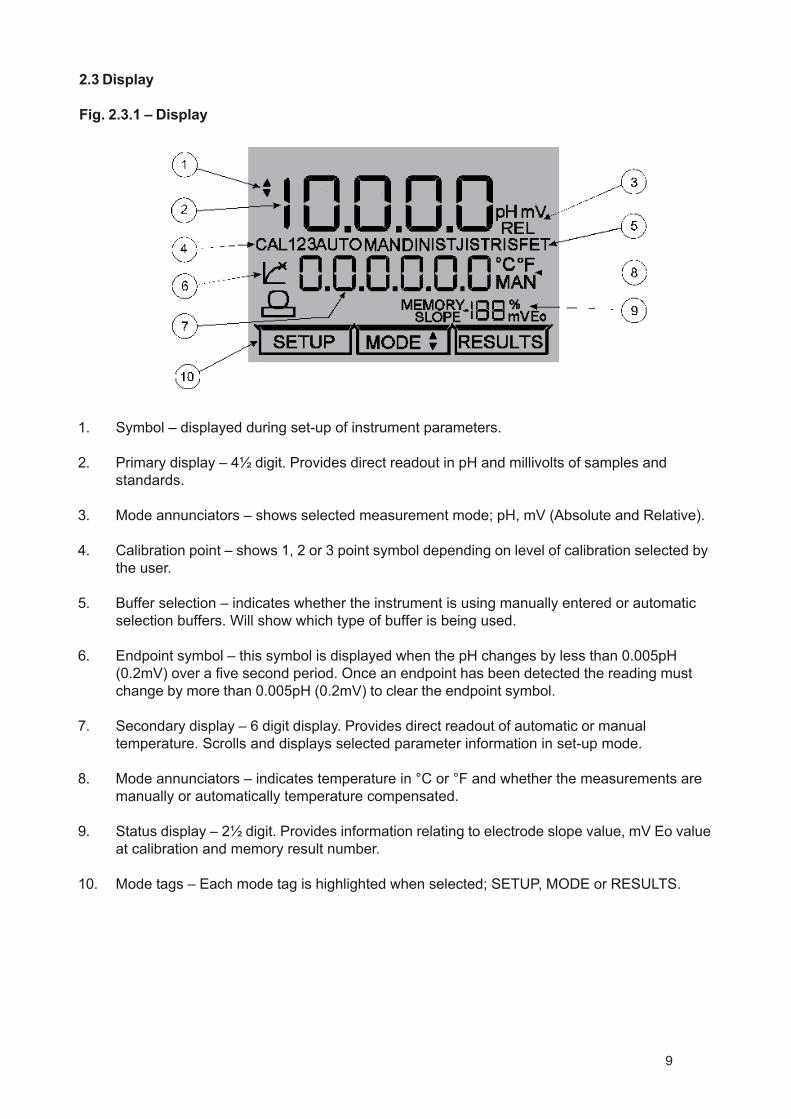
Fig. 2.3.1 – Display
1. Symbol – displayed during set-up of instrument parameters.
2. Primary display – 4½ digit. Provides direct readout in pH and millivolts of samples andstandards.
3. Mode annunciators – shows selected measurement mode; pH, mV (Absolute and Relative).
4. Calibration point – shows 1, 2 or 3 point symbol depending on level of calibration selected bythe user.
5. Buffer selection – indicates whether the instrument is using manually entered or automaticselection buffers. Will show which type of buffer is being used.
6. Endpoint symbol – this symbol is displayed when the pH changes by less than 0.005pH(0.2mV) over a five second period. Once an endpoint has been detected the reading mustchange by more than 0.005pH (0.2mV) to clear the endpoint symbol.
7. Secondary display – 6 digit display. Provides direct readout of automatic or manualtemperature. Scrolls and displays selected parameter information in set-up mode.
8. Mode annunciators – indicates temperature in °C or °F and whether the measurements aremanually or automatically temperature compensated.
9. Status display – 2½ digit. Provides information relating to electrode slope value, mV Eo valueat calibration and memory result number.
10. Mode tags – Each mode tag is highlighted when selected; SETUP, MODE or RESULTS.

10
351 050/REV B/09-064
2.4 Keypad
2.4.1 Keypad
1. ESC used to switch the instrument on and to place into standby mode (only if powersupply lead remains connected to the instrument). Also used to escape/exit amode.
2. CAL / CLR used to select and perform a calibration sequence. This key is also used to clearreadings from Memory. Used to select Abs/Rel mV in mV mode.
3. Print key used to initiate a print.
4. Up Arrow used for adjustment during set up, to scroll results and to toggle between mV andpH modes.
5. Down Arrow used for adjustment during set up, to scroll results and to toggle between mV andpH modes.
6. Left Arrow used for adjustment during set up and to move between mode tags.
7. Right Arrow used for adjustment during set up and to move between mode tags.
8. STO used to accept an entered value in set-up mode and to instigate a storedreading.This key can also be used as a CAL key during calibration.
11
351 050/REV B/09-065
2.5 Inputs/Outputs
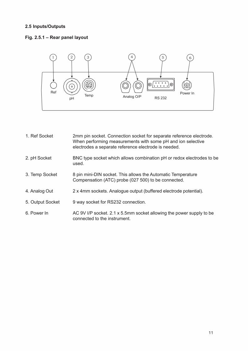
Fig. 2.5.1 – Rear panel layout
1. Ref Socket 2mm pin socket. Connection socket for separate reference electrode.When performing measurements with some pH and ion selectiveelectrodes a separate reference electrode is needed.
2. pH Socket BNC type socket which allows combination pH or redox electrodes to beused.
3. Temp Socket 8 pin mini-DIN socket. This allows the Automatic TemperatureCompensation (ATC) probe (027 500) to be connected.
4. Analog Out 2 x 4mm sockets. Analogue output (buffered electrode potential).
5. Output Socket 9 way socket for RS232 connection.
6. Power In AC 9V I/P socket. 2.1 x 5.5mm socket allowing the power supply to beconnected to the instrument.

12
351 050/REV B/09-066
Section 3
Operation
3.1 Theory of pH Measurement
pH is a unit of measurement which defines the degree of acidity or alkalinity of a solution. It is usu-ally measured on a scale of 0 to 14. The pH value quantifies the degree of hydrogen ion activity ofan acid or a base in terms of hydrogen ion activity.
The internationally accepted symbol, pH, is derived from “p”, the mathematical symbol of thenegative logarithm and “H”, the chemical symbol for Hydrogen. The pH value is the negativelogarithm of Hydrogen ion activity as shown in the mathematical relationship pH= -log[H+].
The pH value of a substance is directly related to the ratio of the Hydrogen ion [H+] and the Hydroxylion [OH-] concentrations. If the concentration of H+ is greater than OH-, the material is acidic andhas a pH value of less than 7. Conversely, if the concentration of OH- is greater than H+ the materialis basic, with a pH value greater than 7. If the concentrations of H+ and OH- are equal the material isneutral with a pH value of 7.
It can, therefore, be seen that pH is a measurement of both acidity and alkalinity, even though bydefinition it is a selective measurement of hydrogen ion activity. The logarithmic relationshipbetween hydrogen ion concentration and the pH unit means that a change of one pH unitrepresents a ten-fold change in hydrogen ion concentration.
3.2 pH Measurement
pH can be measured by using either pH papers/indicators or a pH meter, dependent on the level ofaccuracy required. pH papers or indicators change colour as the pH level varies. These can beused as a guide to the pH level, but can be limited in accuracy and difficult to interpret correctly inmurky or coloured samples.For greater accuracy the use of a high impedance pH meter is recommended, together with a pHmeasuring electrode and reference electrode.
Each component part of the measurement system can be described as follows:
a) the pH meter – is a high impedance amplifier used to accurately measure the minute electrodevoltages produced. The pH meter will display the results directly in pH units on either an analogueor digital display. Voltages can also be read for special applications, ORP (Oxidation-ReductionPotential) measurements or with Ion Selective Electrodes.
b) the pH electrode – is a hydrogen ion sensitive glass bulb, with a millivolt output that varies withthe changes in the relative hydrogen ion concentration inside and outside of the bulb. The pHelectrode has very high internal resistance, making the voltage change with pH difficult to measure.The input impedance of the pH meter and leakage resistances are therefore important factors.
c) the reference electrode – these cells consist of an internal element, usually a silver/silverchloride wire, electrolyte (KCl) and a liquid junction. The liquid junction provides a leak path for theinternal electrolyte to “weep” into the sample chamber and provide an electrical contact with theliquid to be measured. If the liquid junction is inefficient then measurement will be inaccurate. It iscommon for the reference electrode to be incorporated into the pH electrode. It is then called acombination electrode. The Model 3510 meter is supplied with a combination electrode.

13
351 050/REV B/09-067
The voltage developed by each individual pH electrode in the presence of a known hydrogen ionconcentration is theoretically predictable, but in practise deviations from the theoretical value can beexpected. These deviations will change slowly during the life of an electrode. It is therefore essentialto routinely calibrate the system using solutions with a known and constant pH value. Thesesolutions are called buffers.
3.3 Preparation of Buffer Solutions
Care must be taken in the preparation of all buffer solutions. The correct quantity of distilled ordeionised water should be used when preparing the solutions. For accurate and repeatable resultsit is essential to follow the manufacturers instructions carefully.
3.4 Solution Temperature Values
The value of all buffer solutions varies with solution temperature. For accurate calibration ofelectrodes using buffer solutions, it is necessary to measure the temperature of the buffer solutionbeing used. The unit should then be calibrated to the corrected pH value. Manufacturers of bufferpowders and solutions will provide a table of values at varying temperatures for their buffers.
Note: Buffer solutions will contaminate with exposure to air and should be storedin airtight containers when not in use. Used solution should be discarded andnot returned to the container as this will cause contamination.For best results fresh solutions should be prepared prior to calibration.

14
351 030/REV B/09-068
3.5 Good Practice Guidelines
The types of electrodes are many and various. For the majority of tests carried out on aqueoussolutions, with a reasonable ionic strength; at ambient temperatures and with limited use in stronglyacidic or alkaline solutions, the standard glass or epoxy bodied combination electrode is ideal.For other applications a more suitable pH/reference electrode pair may be required; details oradvice supplied on request.
The following general guidelines indicate the care and maintenance required for the three maingroups of electrodes (Combination, Reference and pH). For more detailed advice on specificelectrodes contact the electrode manufacturer.
1) After use Rinse thoroughly with deionised waterShort term storage Immerse in pH 4 buffer (all types)Long term storage Fit wetting cap filled with 3M KCl adjusted to pH 4.
2) Electrodes should be stored a) away from direct sunlightb) in a vertical positionc) within their specified temperature range
3) Always ensure the electrode is used within its specified temperature range. Degradation ofelectrodes used above their specified temperature is rapid and irreversible.
4) Ensure the level of fill solution is above the internal elements in the electrode and that thislevel remains above the sample in use. Note: Some epoxy gel filled electrodes are notrefillable.
5) DO NOT touch the sensitive glass pH membrane or reference junction during use. Excessdroplets of solution may be removed by gently blotting with filter paper or tissue. DO NOT rubthe electrode as this may induce an electrostatic charge.
6) Ensure no air bubbles are trapped at the bottom of the electrode. Removal of air bubbles ispossible by holding the electrode vertically and gently tapping the electrode body. Largerbubbles may be removed by shaking the electrode in a downward direction.
7) During use ensure the electrode is rinsed in deionised water between each measurement toeliminate risk of contamination of solutions.
8) Ensure that the side port/inlet if present is uncovered, especially during a long run of tests.
9) For samples such as blood, serum or any measurements of Tris buffer solutions the junctionmay become badly clogged. For these measurements it is recommended that the Tris bufferelectrode is used (924 030).
10) For applications associated with the measurement of food extracts, it is recommended thatthe Food electrode is used (924 051). This will reduce the risk of blockage from fat proteins,will be easy to clean and is perfect for measurements in agar media. This electrode is alsorecommended for measurement in any solution where deposits on the electrode are likely.The flat surface is easy to clean and robust.
11. For low ionic strength applications the Environmental electrode (924 050) is recommended.

15351 050/REV B/09-069
3.6 Instrument Set-Up
The following section details the set-up modes available to the user.These are: Number of calibration points entry, Buffer type entry, Manual buffer entry 1-3, Displayresolution, Manual temperature, Temperature units and serial port Baud Rate. These can be set insequence as detailed in this section or, by entering the SETUP mode and using the STO key toselect a specific parameter at any time.
To exit the set up menus at any time press the ESC key. This will return the instrument to theMODE menu. Any parameters not saved will remain as defaults or previous setting.
3.6.1 Number of calibration points entry
I, 2 or 3 point calibration is possible on the 3510. To set these parameters:
Select SETUP mode on the display using the Left arrow key.
The secondary display will show CALPTS and will then scroll CALIBRATION POINTS after 10seconds.
Select the required number of calibration points using the Up/Down arrow keys. The Left/Rightarrow keys and the CAL/CLR key have no function during this set up.
Symbol will flash while adjustment is being made.
To accept the number of calibration points entered, press the STO key. The symbol will disappearand the secondary display will momentarily show SAVED and the next set up menu option will bedisplayed.

16
351 050/REV B/09-0610
3.6.2 Buffer type entry
The display will show:
The secondary display will show BUFFER and will then scroll BUFFER TYPE after 10 seconds.Select the type of buffer from the options available by scrolling through the list using the Up/Downarrows – AUTO, MAN, JIS, NIST or DIN. (AUTO relates to the Jenway buffer types supplied with theinstrument).
with the first digit of the value flashing. Adjustment of the flashing digit can be made using the Up/Down arrow keys. The Left/Right arrow keys are used to select the next adjusting digit which willflash when selected. Once the full reading has been adjusted to the correct value, press the STOkey. If a 1 point calibration only is being performed the instrument display will update and show thepH Resolution set up menu.
The Left/Right arrow keys and the CAL/CLR key have no function during this set up.
Symbol will flash while adjustment is being made.
To accept the type of buffer selected, press the STO key. The symbol will disappear and thesecondary display will momentarily show SAVED and the next set up menu option will be displayed.
If MANUAL buffer entry is selected the display will show SAVED and then the screen will update toshow:

17
3.6.3 pH resolution
Note: Setting the pH resolution will affect the resolution on the main instrument display.Manual buffer entry is always shown to 3 decimal places.
The display will show:
The secondary display will show PH RES and will then scroll PH RESOLUTION after 10 seconds.
Select the preferred resolution from the options (0.001, 0.01 or 0.1) using the Up/Down arrows.
The Left/Right arrow keys and the CAL/CLR key have no function during this set up.
Symbol will flash while adjustment is being made.
To accept the selected resolution, press the STO key. The symbol will disappear and the secondarydisplay will momentarily show SAVED and the next set up menu option will be displayed.
To exit the set up menus at any time press the ESC key. This will return the instrument to theMODE menu.
11 351 050/REV B/09-06
The correct values should be entered and saved as for the 1 point calibration. When all chosenbuffer types have been entered and confirmed the instrument display will update to show the nextset up menu option.
To exit the set up menus at any time press the ESC key. This will return the instrument to theMODE menu.
If a 2 or 3 point calibration is being performed the display will move on to the 2 and then 3 pointcalibration buffer set up screens.

18
351 050/REV B/09-0612
3.6.4 Temperature units
The display will show:
The secondary display will show UNITS and will then scroll TEMPERATURE UNITS after 10seconds.
Select °C or °F using the Up/Down arrows.
The Left/Right arrow keys and the CAL/CLR key have no function during this set up.
Symbol will flash while adjustment is being made.
To accept °C or °F, press the STO key. The symbol will disappear and the secondary display willmomentarily show SAVED and the next set up menu option will be displayed.
To exit the set up menus press the ESC key at any time. This will return the instrument to theMODE menu.
3.6.5 Manual temperature
If the ATC probe is not connected to the instrument the display will show:
The secondary display will show MAN °C (or °F) and will then scroll MANUAL TEMPERATURE °C(or °F).
Measure the temperature of the buffer solutions(s) to be used and adjust the displayed reading tothese values. Adjustment of the flashing digit can be made using the Up/Down arrow keys. TheLeft/Right arrow keys are used to select the next adjusting digit which will flash when selected.Once the reading has been adjusted to the correct value, press the STO key. The instrumentdisplay will update and show the Baud Rate set up menu.
Any changes to manual temperature settings reflect on 3.6.4.
To exit the set up menus press the ESC key at any time. This will return the instrument to theMODE menu.
19
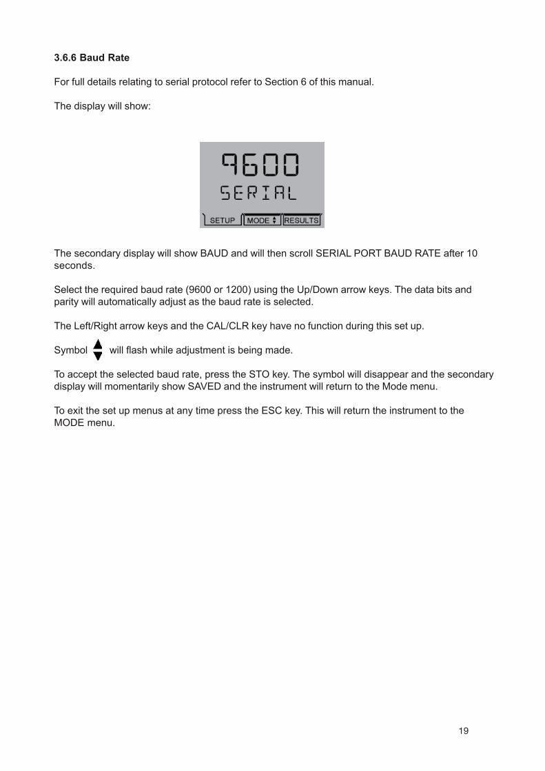
The secondary display will show BAUD and will then scroll SERIAL PORT BAUD RATE after 10seconds.
Select the required baud rate (9600 or 1200) using the Up/Down arrow keys. The data bits andparity will automatically adjust as the baud rate is selected.
The Left/Right arrow keys and the CAL/CLR key have no function during this set up.
Symbol will flash while adjustment is being made.
To accept the selected baud rate, press the STO key. The symbol will disappear and the secondarydisplay will momentarily show SAVED and the instrument will return to the Mode menu.
To exit the set up menus at any time press the ESC key. This will return the instrument to theMODE menu.
3.6.6 Baud Rate
For full details relating to serial protocol refer to Section 6 of this manual.
The display will show:
351 050/REV B/09-0613

20
3.7 pH Calibration
3.7.1 Calibration with Manual Temperature Compensation
To exit the calibration sequence at any time press the ESC key. This will cancel the pH calibrationand return the instrument to the MODE menu.
Note: Buffer solutions should be carefully prepared as per the manufacturers instructions.When using manual temperature compensation (no ATC probe fitted) the solutiontemperature should be measured and the value entered in the set up menu prior tocalibrating the instrument (refer 3.6.5). The buffer solutions should all be at the sametemperature.
1. Select the pH measuring mode using the Up/Down arrows which toggle between pH and mVmodes. Press the CAL key.The primary display will show the current pH reading. The main display annunciators will indicateCAL 1 and the buffer type being used.The secondary display will show the manually set temperature reading in °C or °F. When manualtemperature compensation is being used the annunciator will indicate MAN.The status display will indicate the slope value.
2. CAL 1 Immerse the electrode(s) in the first buffer solution and allow the instrument to stabilise.When no pH change of less than 0.005pH is detected over a five second period the endpointsymbol will be displayed. Press the CAL or STO key.
If a successful I point calibration has been performed the secondary display will momentarily showCAL OK. The instrument will then update the display. The display will then show the next part of thecalibration sequence if a 2 and/or 3 point calibration has been selected. If a 1 point calibration onlyis required the instrument will return to the main measuring screen. Eo is shown on the statusdisplay
Rinse the electrode(s) in deionised water.
3. CAL 2 Immerse the electrode(s) in the second buffer solution and allow the instrument tostabilise. When no pH change of less than 0.005pH is detected over a five second period theendpoint symbol will be displayed. Press the CAL or STO key. The slope value is shown on thestatus display.
14 351 050/REV B/09-06

21
If a successful calibration has been performed the secondary display will momentarily show CALOK. The instrument will then update the display. The display will then show the next part of thecalibration sequence if a 3 point calibration has been selected. If a 2 point calibration only isrequired the instrument will return to the main measuring screen.
Rinse the electrode(s) in deionised water.
4. CAL 3 Immerse the electrode(s) in the third buffer solution and allow the instrument to stabilise.When no change in the least significant display digit is detected over a five second period theendpoint symbol will be displayed. Press the CAL or STO key.
15 351 050/REV B/09-06
If a successful I point calibration has been performed the secondary display will momentarily showCAL OK. The instrument will then update the display.
Rinse the electrode(s) in deionised water.
Once a successful calibration has been completed the instrument will return to the measuringmode.
The instrument is then ready to undertake the measurement of unknown solutions. If the tempera-ture of the unknown solution differs from the buffer, the Set up menu should be used to set theinstrument display to the temperature of the unknown solution.
If the instrument fails a calibration the error message ERROR E) OUTSIDE LIMITS will scroll alongthe secondary display. (refer Section 3.8 for details of Error Codes).

22
3.7.2 Calibration with Automatic Temperature Compensation
To exit the calibration sequence at any time press the ESC key. This will cancel the pH calibrationand return the instrument to the MODE menu.
Note: Buffer solutions should be carefully prepared as per the manufacturers instructions.
1. Select the pH measuring mode using the Up/Down arrows which toggle between pH and mVmodes. Press the CAL key.The primary display will show the current pH reading. The main display annunciators will indicateCAL 1 and the buffer type being used.The secondary display will show the ATC temperature in °C or °F.The status display will indicate the Eo or slope values.
2. CAL 1 Immerse the electrode(s) in the first buffer solution and allow the instrument to stabilise.When no change in the least significant display digit is detected over a five second period theendpoint symbol will be displayed. Press the CAL or STO key.
351 050/REV B/09-0616
If a successful I point calibration has been performed the secondary display will momentarily showCAL OK. The instrument will then update the display. The display will then show the next part of thecalibration sequence if a 2 and 3 point calibration has been selected. If a 1 point calibration only isrequired the instrument will display the Eo value on the status screen and then return to the mainmeasuring screen.
Rinse the electrode(s) in deionised water.
3. CAL 2 Immerse the electrode(s) in the second buffer solution and allow the instrument to stabi-lise. When no change in the least significant display digit is detected over a five second period theendpoint symbol will be displayed. Press the CAL or STO key.
If a successful calibration has been performed the secondary display will momentarilyshow CAL OK. The instrument will then update the display. The display will then showthe next part of the calibration sequence if a 3 point calibration has been selected. If a 2point calibration only is required the instrument will return to the main measuring screen.
Rinse the electrode(s) in deionised water.

23
17
3.8 Error Codes
4. CAL 3 Immerse the electrode(s) in the third buffer solution and allow the instrument to stabilise.When no change in the least significant display digit is detected over a five second period theendpoint symbol will be displayed. Press the CAL or STO key.
If a successful I point calibration has been performed the secondary display will momentarily showCAL OK. The slope value from the calibration will be displayed. The instrument will then update thedisplay.
Rinse the electrode(s) in deionised water.
If the instrument fails a calibration the error message EO will be shown and ERROR SLOPEOUTSIDE LIMITS will scroll along the secondary display.
351 050/REV B/09-06
ERROR EO OUTSIDE LIMITSThis error message will be displayed when the mV value for a buffer is more or less than 30mVfrom the ideal Nernstian value.
ERROR SLOPE OUTSIDE LIMITSThis error message is displayed when the slope value is outside the range of 75 - 125%.
UNABLE TO RECOGNISE BUFFERThis error message will be displayed when the buffer value is more than 0.5 pH units from the setvalue.

24
3.9 Millivolt Mode
Absolute Millivolts
When this mode is selected the unit will display the actual voltage developed by the electrode when itis immersed in a solution containing ions to which the electrode is sensitive.The electrode may be a combination type or a suitable sensing/reference pair, depending on thespecific test being carried out.
pH, Redox and Ion Selective electrodes can all be used in this mode. Most of these determinations willrequire the preparation of calibration curves or other analytical methods to enable the mV reading tobe converted to a concentration unit. For further information on these determinations refer to theelectrode instructions, which will normally give details of calibration solutions, interferences and thelimits of the methodology.
A very useful application of the Absolute mV range is for monitoring the performance of standard pHelectrodes. Using accurate and fresh buffers at a constant temperature, the millivolt output of theelectrode should be noted and compared to the theoretical ideal. As the electrode ages, becomescontaminated or dirty, these values will drift, indicating that corrective action should be taken.Recording these values as part of a routine Quality Control program can give a good indication of thecondition of the electrode.
351 050/REV B/09-06
Relative MillivoltsThis mode is suitable for determinations using Redox and Ion Selective Electrodes and has theadditional benefit of being able to zero any offset voltage developed by the electrode in a blank solution,i.e; a solution that has none of the ions to be measured, but has all the other characteristics of theunknown samples. A blank solution would normally have its ionic strength and pH adjusted as requiredfor the electrode in use.As the display is zeroed automatically when the Relative millivolt mode is selected, it is necessary toimmerse the electrode in the blank solution with the Absolute mV mode selected. When the readinghas stabilised the Relative mV mode should then be selected. The display will be set to zero, therebyremoving any offset voltage.Sample measurement is then carried out by using a variety of well tried analytical methods; fromsimple calibration curves through titrations, to single and multiple addition methods.
Select the mV mode using the Up/Down arrows which toggle between pH and mV modes.The CAL/CLR key switches between Absolute and Relative mV. Relative mV is indicated by REL onthe display.
18

25
3.10 Performing Measurements
To perform measurements in pH, mV or temperature modes the following should be carried out:
1. mV Measurementa) Connect the electrode to the unit via the BNC socket on the rear panel. If a separatereference electrode is to be used, this should be connected to the Ref socket.b) Select mV mode using the Up/Down arrows. The display will show the electrode outputdirectly in mV.
2. Temperature Measurement (using ATC)a) Connect the ATC probe to the unit via the Temp socket on the rear panel.b) Select °C or °F via the Set up menu.The secondary display will show ATC probe temperature directly in °C or °F.
3. Temperature Measurement (Manual)a) If Manual temperature compensation is being used, the preferred measurement rangeshould be selected via the Set Up menu.b) Immerse the electrode into the solution and set the to the solution temperature via the SetUp menu.
4. pH Measurementa) Perform a calibration sequence using manual or automatic temperature compensation.b) Immerse the electrode(s) into the solution to be measured and note the results once thereading has stabilised.
NOTE: Ensure the pH/Reference probe combination are compatible with the samples beingmeasured. Non-compatibility may be indicated by drifting readings, noise or shortenedelectrode life. During use the electrode must be rinsed between each measurement toeliminate contamination of solutions. Excess droplets of solution may be removed bygently blotting with filter paper or tissue.For further details refer to Section 3.5-Good Practice Guidelines.
351 050/REV B/09-0619

26
3.11 Results storage and display
To store the current displayed result press the STO key. The instrument display will momentarilyshow STORED on the secondary display. The memory location will be given on the status display.
Up to 32 results can be stored. Each result will be stored in the next available memory location.
The instrument will store: Primary pH or mV readingsTemperature readings and the unit of measurement (°C or °F)MAN if manual temperature measurement is usedEndpoint symbolREL if relative mV is selected
Selecting the RESULTS menu displays the reading stored at the displayed memory location.
The Up arrow increments the memory index, the Down arrow decrements the memory index.
The Left arrow exits to the main measurement display.
The Right arrow and STO keys do not function.
CAL/CLR deletes the current memory location. The secondary display scrolls DELETED.
Holding the CAL/CLR key until after DELETED is displayed on the screen will delete all readings.The secondary display will then scroll ALL RECORDS DELETED.
If no readings have been stored, the secondary display will show EMPTY.
To exit this mode press the ESC key.
If the memory is full the secondary display will show FULL.
351 050/REV B/09-0620

27
Section 4
Maintenance
4.1 General
The Model 3510 is designed to give optimum performance with minimum maintenance. It is onlynecessary to keep the external surfaces clean and free from dust. To give added protection whennot in use the unit should be switched off and covered with the optional dust cover (060 406).
4.2 Cleaning/Re-conditioning of Combination Electrodes
For general purpose use, combination electrodes can be cleaned with a mild detergent solution or acommercial glass cleaning solution (provided these are not strongly acidic). The electrode surfaceshould be wiped with a clean cloth soaked in the cleaning agent, and/or allow the membrane tostand in the solution until clean. Rinse and repeat as necessary. Electrodes which have beenallowed to dry out should be soaked overnight in warm distilled water.
Table of Cleaning Agents for Glass Electrodes
DepositGeneral depositsInorganic coatingsMetal compoundsOil/GreaseResins/LigninsProteins (blood, etc)Stubborn deposits
Cleaning AgentGenklene or mild detergent solutionCommercial glass cleaning solution (not strongly acidic)Acid solution, not stronger than 1MComplexing agent (EDTA) or suitable solventAcetone, alcohol or detergent (not strongly acidic)Enzyme solutions (e.g; pepsin in 0.1M HCl)Hydrogen peroxide, sodium hypochlorite or domestic bleach
Note: Solvents such as carbon tetrachloride, trichloroethylene, petroleum, ether, etc,MUST NOT be used for cleaning electrodes that have a plastic body or a plastic protectiveskirt.
351 050/REV B/09-0621

28
Section 5
Optional Accessories
The following list of items are available as optional accessories for use with the Model 3510:
060 406 Dust cover037 701 Printer supplied with roll of thermal paper, serial connection lead, power supply,
power connection lead (UK) and pouch037 801 Interface cable kit050 501 DataWay PC Software - includes CD-ROM, interface cable and instructions037 551 RS232 to USB converter for use with computers without a serial port
pH electrodes
924 001 General purpose, epoxy bodied combination, 12mm diameter. For liquids.924 005 General purpose, glass bodied combination, 12mm diameter. For liquids.
For a complete listing of all available electrodes please contact your local distributor.
Buffer Solutions Redox Standards025 163 2.00 pH buffer (500ml) 025 157 200mV @ 25°C (500ml)025 037 4.00 pH buffer (500ml) 025 158 300mV @ 25°C (500ml)025 038 7.00 pH buffer (500ml) 025 159 465mV @ 25°C (500ml)025 162 9.22 pH buffer (500ml)025 039 10.05 pH buffer (500ml)025 179 pH 4 buffer sachets (pack of 10)025 180 pH 7 buffer sachets (pack of 10)025 181 pH 10 buffer sachets (pack of 10)
Miscellaneous025 160 3M KCl Electrode Fill Solution (100ml)025 161 Electrode Cleaning Solution (500ml)
5.2 Spares924 005 pH combination electrode (glass bodied)027 500 ATC probe009 146 BNC shorting plug037 702 Paper roll, thermal021 030 UK 230V power supply021 031 European 230V power supply021 032 US 115V power supply021 033 230V leaded power supply
351 050/REV B/09-062233
Section 5
Optional Accessories
5.1 Optional Accessories
The following list of items are available as optional accessories for use with the Model 3520:
060 406 Dust cover037 701 IrDA printer supplied with roll of thermal paper, serial connection lead, power supply,
power connection lead (UK) and pouch037 801 Interface cable kit
pH electrodes
924 001 General purpose, epoxy bodied combination, 12mm diameter. For liquids.924 005 General purpose, glass bodied combination, 12mm diameter. For liquids.
For a complete listing of all available electrodes please contact your local distributor.
Buffer Solutions Redox Standards025 163 2.00 pH buffer (500ml) 025 157 200mV @ 25°C (500ml)025 037 4.00 pH buffer (500ml) 025 158 300mV @ 25°C (500ml)025 038 7.00 pH buffer (500ml)025 162 9.22 pH buffer (500ml)025 039 10.05 pH buffer (500ml)025 179 pH 4 buffer sachets (pack of 10)025 180 pH 7 buffer sachets (pack of 10)025 181 pH 10 buffer sachets (pack of 10)
Miscellaneous025 160 3M KCl Electrode Fill Solution (100ml)025 161 Electrode Cleaning Solution (500ml)
5.2 Spares
924 005 pH combination electrode (glass bodied)027 500 ATC probe009 146 BNC shorting plug037 702 Paper roll, thermal021 030 UK 230V power supply021 031 European 230V power supply021 032 US 115V power supply021 033 230V leaded power supply
352 050/REV A/03-0327
060 406 Dust Cover037 701 IrDA printer supplied with roll of thermal paper, serial connection lead, power supply, power connection lead (UK) and pouchM7817X6 EU Power supply for printerM7817X1 US Power supply for printer037 801 Interface cable kit
33
Section 5
Optional Accessories
5.1 Optional Accessories
The following list of items are available as optional accessories for use with the Model 3520:
060 406 Dust cover037 701 IrDA printer supplied with roll of thermal paper, serial connection lead, power supply,
power connection lead (UK) and pouch037 801 Interface cable kit
pH electrodes
924 001 General purpose, epoxy bodied combination, 12mm diameter. For liquids.924 005 General purpose, glass bodied combination, 12mm diameter. For liquids.
For a complete listing of all available electrodes please contact your local distributor.
Buffer Solutions Redox Standards025 163 2.00 pH buffer (500ml) 025 157 200mV @ 25°C (500ml)025 037 4.00 pH buffer (500ml) 025 158 300mV @ 25°C (500ml)025 038 7.00 pH buffer (500ml)025 162 9.22 pH buffer (500ml)025 039 10.05 pH buffer (500ml)025 179 pH 4 buffer sachets (pack of 10)025 180 pH 7 buffer sachets (pack of 10)025 181 pH 10 buffer sachets (pack of 10)
Miscellaneous025 160 3M KCl Electrode Fill Solution (100ml)025 161 Electrode Cleaning Solution (500ml)
5.2 Spares
924 005 pH combination electrode (glass bodied)027 500 ATC probe009 146 BNC shorting plug037 702 Paper roll, thermal021 030 UK 230V power supply021 031 European 230V power supply021 032 US 115V power supply021 033 230V leaded power supply
352 050/REV A/03-0327
060 406 Dust Cover037 701 IrDA printer supplied with roll of thermal paper, serial connection lead, power supply, power connection lead (UK) and pouchM7817X6 EU Power supply for printerM7817X1 US Power supply for printer037 801 Interface cable kit
Section 5
Optional Accessories
The following list of items are available as optional accessories for use with the Model 3510:
060 406 Dust cover037 701 Printer supplied with roll of thermal paper, serial connection lead, power supply,
power connection lead (UK) and pouch037 801 Interface cable kit050 501 DataWay PC Software - includes CD-ROM, interface cable and instructions037 551 RS232 to USB converter for use with computers without a serial port
pH electrodes
924 001 General purpose, epoxy bodied combination, 12mm diameter. For liquids.924 005 General purpose, glass bodied combination, 12mm diameter. For liquids.
For a complete listing of all available electrodes please contact your local distributor.
sdradnatS xodeRsnoituloS reffuB025 163 2.00 pH buffer (500ml) 025 157 200mV @ 25°C (500ml)025 037 4.00 pH buffer (500ml) 025 158 300mV @ 25°C (500ml)025 038 7.00 pH buffer (500ml) 025 159 465mV @ 25°C (500ml)025 162 9.22 pH buffer (500ml)025 039 10.00 pH buffer (500ml)025 179 pH 4 buffer sachets (pack of 10)025 180 pH 7 buffer sachets (pack of 10)025 181 pH 10 buffer sachets (pack of 10)
Miscellaneous025 160 3M KCl Electrode Fill Solution (100ml)025 161 Electrode Cleaning Solution (500ml)
5.2 Spares924 005 pH combination electrode (glass bodied)027 500 ATC probe009 146 BNC shorting plug037 702 Paper roll, thermal021 030 UK 230V power supply021 031 European 230V power supply021 032 US 115V power supply021 033 230V leaded power supply
351 050/REV B/09-0622

29
351 050/REV B/09-0623
SECTION 6
Interfacing
6.1 Analogue
All units are provided with 2 x 4mm sockets, marked as ANALOG OUT, on the rear panel. An analogueoutput voltage of 1mV per least significant digit is available from these sockets. Recorder output±2000mV, proportional to displayed reading:
1mV per 0.01pH (pH measurement and calibration modes)1mV per 1mV (mV measurement mode)
6.2 RS232
The Bi-directional RS232 interface is available on the rear panel 9 way D type connector.The connections are as follows:
DCD 1 - LINKED TO DTR AND DSRRXD 2 - INPUT TO 3510TXD 3 - OUTPUT FROM 3510DTR 4 - LINKED TO DCD AND DSRGND 5DSR 6 - LINKED TO DCD AND DTRRTS 7 - OUTPUT FROM 3510CTS 8 - INPUT TO 3510
Suggested interconnections are detailed below:
3510 IBM PC XT (25 way “D”)1 DCD DCD 82 RXD RXD 33 TXD TXD 24 DTR DTR 205 GND GND 76 DSR DSR 67 RTS RTS 48 CTS CTS 59
3510 IBM PC XT (9 way “D”)1 DCD 1 DCD2 RXD 2 RXD3 TXD 3 TXD4 DTR 4 DTR5 GND 5 GND6 DSR 6 DSR7 RTS 7 RTS8 CTS 8 CTS9 9
NOTE: Interface Cable (Order Code: 013 203) is required.

30
Interfacing (continued)
The RS232 communications parameters on the computer or printer need to be set to match those ofthe Model 3510, as detailed below:
1200 Baud 9600 Baud7 Data Bits 8 data bitsOdd Parity OR No parity1 Stop Bit 1 stop bit
Setting of these options is detailed in Section 3.6.6.
The Model 3510 supports both hardware (CTS/RTS) flow control and software XON/XOFF flow control.
Pressing the PRINT key outputs from the RS232 interface.
Sending an ASCII “D” to the 3510 causes a printout of the current displayed reading plus samplenumber.
Sending an ASCII “C” causes a printout of the last calibration parameters.
Sending an ASCII "P" causes a printout of the stored readings.
6.3 Keypad Emulation
351 050/REV B/09-0624
Keypad remote control using RS232 interface:
7 - Instrument On / Standby / Escape
1 - Calibrate / Memory Clear
9 - Print
8 - Up Arrow
2 - Down Arrow
4 - Left Arrow
6 - Right Arrow
3 or 5 - Enter / Store

31
25 351 050/REV B/09-06
6.4 Printing
A 32 column serial printer (037 701) is available for use with the Model 3510.
Connect the printer via the cable supplied with the printer to the 9 way socket located on the rearpanel of the instrument.
To intiate a print out of data press the print key.
When the first print is performed a header section will be printed showing:
Instrument nameSpacing for entry of Operator & User IDMost recent calibration informationEo valueSlope efficiencyBuffer type
This will be followed by results data in either pH or mV dependent on mode selected. Details willalso be given on temperature.
An asterisk (*) indicates that manual temperature compensation is being used.
A reading in the Relative mV mode will be indicated by an R.
Each reading will be numbered sequentially.
A calibration will reset the data number to 0001 and the header information will be re-printed.
To obtain a print out of stored readings, enter the RESULTS MODE and press the print key. A printout of all 32 print locations will then be generated.

32
6.4.1 Example Printout
3510 Header printout 3510 Results printout
26 351 050/REV B/09-06

33
Section 7
Troubleshootiing and functional checks
7.1 Troubleshooting
Fault Possible Cause Action
No display Check power supply Check that correct 9V ac power supplyis connected and switched on.
Erratic display Check power supply Unit must be used with supplied 9Vacpower supply. Usage of other units willcause the 3510 not to operate.
Drifting erratic readings Electrode fault Use BNC cap to test 3510 (see 7.2)Replace electrode.
Cannot calibrate Electrode Fault Use BNC cap to test 3510 (see 7.2)Replace electrode.
ERROR EO ... Buffer problem Use freshly prepared buffers.ERROR SLOPE .... Electrode problem Use BNC cap to test 3510 (see 7.2)
Replace electrode.
Unable to recognise Using correct buffer set Is the buffer type correct? Use AUTO forbuffers Jenway supplied buffers.
Replace buffersUse BNC cap to test 3510 (see 7.2)Replace electrode.
Temperature readings Temp probe faulty Check 3510 using section 7.2fluctuating Replace temperature probe.
Temperature readings Temp probe faulty Check 3510 using section 7.2incorrect Replace temperature probe.
Manual temp not set Set meter to read °C and settemperature against a calibratedthermometer.
Will not print Connection 3510 requires the RS232 cable toconnect the printer.
Paper out The feed light on the printer will flash ifthe unit requires paper.
Battery flat Connect ac power supply.
If the above does not answer your query try the FAQ section on the www.Jenway.com Website.
351 050/REV B/09-0627

34
Temperature input check.
Remove the temperature probe and apply a 10Kohm resistor across the pins of the temp input asdescribed in fig 7.2.1
Fig 7.2.1 Temperature input with connection detail
351 050/REV B/09-0628
7.3 Reset Procedure
NOTE: Performing a reset will return all options to the default values. It will not deletestored data.
1. Remove AC power connector from the rear panel socket.
2. Press and hold the STO key.
3. Replace the AC power connector into the rear panel socket. The secondary display willmomentarily show E2 RST.
4. If this does not resolve the problem please contact the manufacturer or your local distributor.
7.2 Functional check
The measurement function of the meter can be checked using the enclosed BNC shorting cap(009 146).
1) Remove the ATC probe if connected.2) Set Manual temperature compensation to 25°C.3) Remove pH probe and replace with BNC shorting cap.4) Select mV mode the display should read ±1.
If the mV reading is greater than ±1mV perform a reset (refer Section 7.3).
To make measurements from this point refit the ATC probe and pH probe and calibrate the 3510using fresh buffer solutions (see section 3.6).

EU Declaration of Conformity
This declaration of conformity is issued under the sole responsibility of the manufacturer
Signed for and on behalf of the above manufacturer
Product Laboratory Equipment
Manufacturer Cole-Parmer Ltd Beacon Road Stone, Staffordshire ST15 0SA United Kingdom
File Number P225
Authorised Cole-ParmerRepresentative Beacon Road Stone, Staffordshire ST15 0SA United Kingdom
Object of DeclarationpH and Conductivity Meters - Bench Range(reference the attached list of catalogue numbers)
The object of the declaration described above is in conformity with the relevant Union Harmonisation Legislation:
Additional Information
Place of Issue
Date of Issue
Authorised Representative
Title
Signature
References to the relevant harmonised standards used or references to the other technical specifications in relation to which conformity is declared:
IEC/EN 61010-1:2001Safety requirements for electrical equipment formeasurement, control and laboratory use.Part 1: General requirements.
Electrical equipment for measurement, control andlaboratory use. EMC requirements.Part 1: General requirements (Class A).
IEC/EN 61326-1:2006
Low Voltage DirectiveEMC DirectiveRoHS Directive
2004/108/EC2006/95/EC2011/65/EC
Year of CE Marking: 2003
Stone, Staffordshire, UK
October 2009
Carl Warren
Technical Manager
EU Declaration of Conformity
This declaration of conformity is issued under the sole responsibility of the manufacturer
Signed for and on behalf of the above manufacturer
Product Laboratory Equipment
Manufacturer Cole-Parmer Ltd Beacon Road Stone, Sta�ordshire ST15 0SA United Kingdom
File Number P225
Authorised Cole-ParmerRepresentative Beacon Road Stone, Sta�ordshire ST15 0SA United Kingdom
Object of Declaration pH and Conductivity Meters - Bench Range(reference the attached list of catalogue numbers)
The object of the declaration described above is in conformity with the relevant Union Harmonisation Legislation:
Additional Information
Place of Issue
Date of Issue
Authorised Representative
Title
Signature
References to the relevant harmonised standards used or referento which conformity is declared:
IEC/EN 61010-1:2001Safety requirements for electrical equipment formeasurement, cont rol and laboratory use.Part 1: General requirements.
Electrical equipment for measu rement, cont rol andlaboratory use. EMC requirements.Part 1: General requirements (Class A).
IEC/EN 61326-1:2006
Low Voltage DirectiveEMC DirectiveRoHS Directive
2004/108/EC2006/95/EC2011/65/EC
Year of CE Marking: 2003
Stone, Sta�ordshire, UK
October 2009
Carl Warren
Technical Manager
39
EU Declaration of Conformity
This declaration of conformity is issued under the sole responsibility of the manufacturer
Signed for and on behalf of the above manufacturer
Product Laboratory Equipment
Manufacturer Cole-Parmer Ltd Beacon Road Stone, Staffordshire ST15 0SA United Kingdom
File Number P225
Authorised Cole-ParmerRepresentative Beacon Road Stone, Staffordshire ST15 0SA United Kingdom
Object of DeclarationpH and Conductivity Meters - Bench Range(reference the attached list of catalogue numbers)
The object of the declaration described above is in conformity with the relevant Union Harmonisation Legislation:
Additional Information
Place of Issue
Date of Issue
Authorised Representative
Title
Signature
References to the relevant harmonised standards used or references to the other technical specifications in relation to which conformity is declared:
IEC/EN 61010-1:2001Safety requirements for electrical equipment formeasurement, control and laboratory use.Part 1: General requirements.
Electrical equipment for measurement, control andlaboratory use. EMC requirements.Part 1: General requirements (Class A).
IEC/EN 61326-1:2006
Low Voltage DirectiveEMC DirectiveRoHS Directive
2004/108/EC2006/95/EC2011/65/EC
Year of CE Marking: 2003
Stone, Staffordshire, UK
October 2009
Carl Warren
Technical Manager
EU Declaration of Conformity
This declaration of conformity is issued under the sole responsibility of the manufacturer
Signed for and on behalf of the above manufacturer
Product Laboratory Equipment
Manufacturer Cole-Parmer Ltd Beacon Road Stone, Sta�ordshire ST15 0SA United Kingdom
File Number P225
Authorised Cole-ParmerRepresentative Beacon Road Stone, Sta�ordshire ST15 0SA United Kingdom
Object of Declaration pH and Conductivity Meters - Bench Range(reference the attached list of catalogue numbers)
The object of the declaration described above is in conformity with the relevant Union Harmonisation Legislation:
Additional Information
Place of Issue
Date of Issue
Authorised Representative
Title
Signature
References to the relevant harmonised standards used or referento which conformity is declared:
IEC/EN 61010-1:2001Safety requirements for electrical equipment formeasurement, cont rol and laboratory use.Part 1: General requirements.
Electrical equipment for measu rement, cont rol andlaboratory use. EMC requirements.Part 1: General requirements (Class A).
IEC/EN 61326-1:2006
Low Voltage DirectiveEMC DirectiveRoHS Directive
2004/108/EC2006/95/EC2011/65/EC
Year of CE Marking: 2003
Stone, Sta�ordshire, UK
October 2009
Carl Warren
Technical Manager
EU Declaration of Conformity
This declaration of conformity is issued under the sole responsibility of the manufacturer
Signed for and on behalf of the above manufacturer
Product Laboratory Equipment
Manufacturer Cole-Parmer Ltd Beacon Road Stone, Sta�ordshire ST15 0SA United Kingdom
File Number P225
Authorised Cole-ParmerRepresentative Beacon Road Stone, Sta�ordshire ST15 0SA United Kingdom
Object of Declaration pH and Conductivity Meters - Bench Range(reference the attached list of catalogue numbers)
The object of the declaration described above is in conformity with the relevant Union Harmonisation Legislation:
Additional Information
Place of Issue
Date of Issue
Authorised Representative
Title
Signature
References to the relevant harmonised standards used or referento which conformity is declared:
IEC/EN 61010-1:2001Safety requirements for electrical equipment formeasurement, cont rol and laboratory use.Part 1: General requirements.
Electrical equipment for measu rement, cont rol andlaboratory use. EMC requirements.Part 1: General requirements (Class A).
IEC/EN 61326-1:2006
Low Voltage DirectiveEMC DirectiveRoHS Directive
2004/108/EC2006/95/EC2011/65/EC
Year of CE Marking: 2003
Stone, Sta�ordshire, UK
October 2009
Carl Warren
Technical Manager
EU Declaration of Conformity
This declaration of conformity is issued under the sole responsibility of the manufacturer
Signed for and on behalf of the above manufacturer
Product Laboratory Equipment
Manufacturer Cole-Parmer Ltd Beacon Road Stone, Sta�ordshire ST15 0SA United Kingdom
File Number P225
Authorised Cole-ParmerRepresentative Beacon Road Stone, Sta�ordshire ST15 0SA United Kingdom
Object of Declaration pH and Conductivity Meters - Bench Range(reference the attached list of catalogue numbers)
The object of the declaration described above is in conformity with the relevant Union Harmonisation Legislation:
Additional Information
Place of Issue
Date of Issue
Authorised Representative
Title
Signature
References to the relevant harmonised standards used or referento which conformity is declared:
IEC/EN 61010-1:2001Safety requirements for electrical equipment formeasurement, cont rol and laboratory use.Part 1: General requirements.
Electrical equipment for measu rement, cont rol andlaboratory use. EMC requirements.Part 1: General requirements (Class A).
IEC/EN 61326-1:2006
Low Voltage DirectiveEMC DirectiveRoHS Directive
2004/108/EC2006/95/EC2011/65/EC
Year of CE Marking: 2003
Stone, Sta�ordshire, UK
October 2009
Carl Warren
Technical Manager
EU Declaration of Conformity
This declaration of conformity is issued under the sole responsibility of the manufacturer
Signed for and on behalf of the above manufacturer
Product Laboratory Equipment
Manufacturer Cole-Parmer Ltd Beacon Road Stone, Sta�ordshire ST15 0SA United Kingdom
File Number P225
Authorised Cole-ParmerRepresentative Beacon Road Stone, Sta�ordshire ST15 0SA United Kingdom
Object of Declaration pH and Conductivity Meters - Bench Range(reference the attached list of catalogue numbers)
The object of the declaration described above is in conformity with the relevant Union Harmonisation Legislation:
Additional Information
Place of Issue
Date of Issue
Authorised Representative
Title
Signature
References to the relevant harmonised standards used or referento which conformity is declared:
IEC/EN 61010-1:2001Safety requirements for electrical equipment formeasurement, cont rol and laboratory use.Part 1: General requirements.
Electrical equipment for measu rement, cont rol andlaboratory use. EMC requirements.Part 1: General requirements (Class A).
IEC/EN 61326-1:2006
Low Voltage DirectiveEMC DirectiveRoHS Directive
2004/108/EC2006/95/EC2011/65/EC
Year of CE Marking: 2003
Stone, Sta�ordshire, UK
October 2009
Carl Warren
Technical Manager
EU Declaration of Conformity
This declaration of conformity is issued under the sole responsibility of the manufacturer
Signed for and on behalf of the above manufacturer
Product Laboratory Equipment
Manufacturer Cole-Parmer Ltd Beacon Road Stone, Staffordshire ST15 0SA United Kingdom
File Number P225
Authorised Cole-ParmerRepresentative Beacon Road Stone, Staffordshire ST15 0SA United Kingdom
Object of Declaration
The object of the declaration described above is in conformity with the relevant Union Harmonisation Legislation:
Additional Information
Place of Issue
Date of Issue
Authorised Representative
Title
Signature
References to the relevant harmonised standards used or references to the other technical specifications in relation to which conformity is declared:
IEC/EN 61010-1:2001Safety requirements for electrical equipment formeasurement, control and laboratory use.Part 1: General requirements.
Electrical equipment for measurement, control andlaboratory use. EMC requirements.Part 1: General requirements (Class A).
IEC/EN 61326-1:2006
Low Voltage DirectiveEMC DirectiveRoHS Directive
2004/108/EC2006/95/EC2011/65/EC
Year of CE Marking: 2010
Stone, Staffordshire, UK
April 2010
Carl Warren
Technical Manager
UV-Visible Spectrophotometer Range - 73 Series(reference the attached list of catalogue numbers)
and so we cannot guarantee that interference will not
occur in practice. Where there is a possibility that injury,damage or loss might occur if equipment malfunctionsdue to radio frequency interference, or for generaladvice before use, contact the manufacturer.
This product meets the applicable EC
harmonised standards for radio frequency interference and may be expected not to interfere with, or be a�ected by, other equipment with similar quali�cations. We cannot be sure that otherequipment used in its vicinity will meet these standards
EU Declaration of Conformity
This declaration of conformity is issued under the sole responsibility of the manufacturer
Signed for and on behalf of the above manufacturer
Product Laboratory Equipment
Manufacturer Cole-Parmer Ltd Beacon Road Stone, Sta�ordshire ST15 0SA United Kingdom
File Number P225
Authorised Cole-ParmerRepresentative Beacon Road Stone, Sta�ordshire ST15 0SA United Kingdom
Object of Declaration pH and Conductivity Meters - Bench Range(reference the attached list of catalogue numbers)
The object of the declaration described above is in conformity with the relevant Union Harmonisation Legislation:
Additional Information
Place of Issue
Date of Issue
Authorised Representative
Title
Signature
References to the relevant harmonised standards used or referento which conformity is declared:
IEC/EN 61010-1:2001Safety requirements for electrical equipment formeasurement, cont rol and laboratory use.Part 1: General requirements.
Electrical equipment for measu rement, cont rol andlaboratory use. EMC requirements.Part 1: General requirements (Class A).
IEC/EN 61326-1:2006
Low Voltage DirectiveEMC DirectiveRoHS Directive
2004/108/EC2006/95/EC2011/65/EC
Year of CE Marking: 2003
Stone, Sta�ordshire, UK
October 2009
Carl Warren
Technical Manager
EU Declaration of Conformity
This declaration of conformity is issued under the sole responsibility of the manufacturer
Signed for and on behalf of the above manufacturer
Product Laboratory Equipment
Manufacturer Cole-Parmer Ltd Beacon Road Stone, Sta�ordshire ST15 0SA United Kingdom
File Number P225
Authorised Cole-ParmerRepresentative Beacon Road Stone, Sta�ordshire ST15 0SA United Kingdom
Object of Declaration pH and Conductivity Meters - Bench Range(reference the attached list of catalogue numbers)
The object of the declaration described above is in conformity with the relevant Union Harmonisation Legislation:
Additional Information
Place of Issue
Date of Issue
Authorised Representative
Title
Signature
References to the relevant harmonised standards used or referento which conformity is declared:
IEC/EN 61010-1:2001Safety requirements for electrical equipment formeasurement, cont rol and laboratory use.Part 1: General requirements.
Electrical equipment for measu rement, cont rol andlaboratory use. EMC requirements.Part 1: General requirements (Class A).
IEC/EN 61326-1:2006
Low Voltage DirectiveEMC DirectiveRoHS Directive
2004/108/EC2006/95/EC2011/65/EC
Year of CE Marking: 2003
Stone, Sta�ordshire, UK
October 2009
Carl Warren
Technical Manager

Cole-Parmer LtdBeacon Road,Stone,Staffordshire, ST15 0SA,United KingdomTel: +44 (0)1785 812121Email: [email protected]: www.jenway.com