Phenomena of vortex shedding and flow interference of...
26
J. Fluid Meeh. (1988), ool. 196, pp. 1-26 Printed in &eat Brifuin 1 Phenomena of vortex shedding and flow interference of three cylinders in different equilateral arrangements By K. LAM AND W. C. CHEUNG Department of Mechanical and Marine Engineering, Hong Kong Polytechnic, Hong Kong (Received 2 June 1987 and in revised form 22 March 1988) This paper describes how the flows around three equal circular cylinders arranged in an equilateral-triangular manner interact at different angles of incidence a and spacing ratios lld. Some vortex-shedding-frequency data evaluated from flow visualization experiments conducted at Reynolds numbers of 2.1 x lo3 and 3.5 x lo3, based on the diameter of a single cylinder, using a dye -injection technique, are presented. In order to provide additional insight to the understanding of the flow structure around this particular cylinder array, some photographs indicating the typical flow patterns for various arrangements are also presented. The investigation indicates that the flows interact in a complex fashion for spacing ratios smaller than 2.29 and it also reveals that, at this range of spacing ratios and at a = Oo, bistable flow characteristic exists. Moreover, for 2/d approximately smaller than 4.65 there always exists an angle at which the vortex shedding behind an upstream cylinder is suppressed by a nearest downstream cylinder. This angle is found not to remain constant but increases as the spacing ratio increases. For illustration and comparisons, some numerical results obtained from the application of the surface- vorticity method have also been presented. 1. Introduction It is well known that when a group of cylinders arranged in close proximity is subjected to cross-flow such as that experienced by heat-exchanger tube banks, transmission cables, chimney stacks, offshore structures and cooling-tower arrays, flow-induced vibration arises. These vibrational problems may in the end lead to the failure or shutdown of industrial facilities which, in turn, could inflict heavy financial losses or even loss of human lives as outlined by Pa'idoussis (1979). In general there are several mechanisms whereby flow-induced oscillations can arise. The most frequently encountered mechanisms are those due to vortex shedding, turbulence, whirling or jet switching (Blevins 1977). Any given structure exposed to fluid flow may experience one or more of these mcchanisms. Among the infinite number of body shapes, the circular cylinder, which forms the basic component of many engineering structures, has received most research attention. Basically the research on flow about a single or multiple circular cylinders has been continuing on two main fronts. One group of workers, e.g. Bearman & Wadcock (1973), Kiya et al. (1980), Igarashi (1981), Bokaian & Geoola (1984) and Zdravkovich (1985) has taken intensive measurements of the vortex-shedding frequency, and mean time-dependent force components on a rigid cylinder pair in various
Transcript of Phenomena of vortex shedding and flow interference of...

J . Fluid Meeh. (1988), ool. 196, p p . 1-26
Printed in &eat Brifuin
1
Phenomena of vortex shedding and flow interference of three cylinders in different equilateral
arrangements
By K . LAM A N D W. C . CHEUNG Department of Mechanical and Marine Engineering, Hong Kong Polytechnic, Hong Kong
(Received 2 June 1987 and in revised form 22 March 1988)
This paper describes how the flows around three equal circular cylinders arranged in an equilateral-triangular manner interact a t different angles of incidence a and spacing ratios l l d . Some vortex-shedding-frequency data evaluated from flow visualization experiments conducted a t Reynolds numbers of 2.1 x lo3 and 3.5 x lo3, based on the diameter of a single cylinder, using a dye -injection technique, are presented. In order to provide additional insight to the understanding of the flow structure around this particular cylinder array, some photographs indicating the typical flow patterns for various arrangements are also presented. The investigation indicates that the flows interact in a complex fashion for spacing ratios smaller than 2.29 and it also reveals that, a t this range of spacing ratios and at a = Oo, bistable flow characteristic exists. Moreover, for 2/d approximately smaller than 4.65 there always exists an angle a t which the vortex shedding behind an upstream cylinder is suppressed by a nearest downstream cylinder. This angle is found not to remain constant but increases as the spacing ratio increases. For illustration and comparisons, some numerical results obtained from the application of the surface- vorticity method have also been presented.
1. Introduction It is well known that when a group of cylinders arranged in close proximity is
subjected to cross-flow such as that experienced by heat-exchanger tube banks, transmission cables, chimney stacks, offshore structures and cooling-tower arrays, flow-induced vibration arises. These vibrational problems may in the end lead to the failure or shutdown of industrial facilities which, in turn, could inflict heavy financial losses or even loss of human lives as outlined by Pa'idoussis (1979).
In general there are several mechanisms whereby flow-induced oscillations can arise. The most frequently encountered mechanisms are those due to vortex shedding, turbulence, whirling or jet switching (Blevins 1977). Any given structure exposed to fluid flow may experience one or more of these mcchanisms. Among the infinite number of body shapes, the circular cylinder, which forms the basic component of many engineering structures, has received most research attention. Basically the research on flow about a single or multiple circular cylinders has been continuing on two main fronts. One group of workers, e.g. Bearman & Wadcock (1973), Kiya et al. (1980), Igarashi (1981), Bokaian & Geoola (1984) and Zdravkovich (1985) has taken intensive measurements of the vortex-shedding frequency, and mean time-dependent force components on a rigid cylinder pair in various

2 K . Lam and W . C. Cheung
geometrical arrangements. Some authors, e.g. Bearman & Wadcock (1973), Igarashi (1981) and Williamson (1985) also used flow-visualization methods to obtain further understanding on the nature of the flow and to give some physical interpretations of their measured data.
On the other hand, much effort has been spent on the theoretical prediction on numerical modelling of vortex shedding behind cylinders, such as the work on single cylinders by, among others, Chorin (1973), Stansby (1977), Sarpkaya & Schoaff (1979), Lewis (1981), Lewis & Porthouse (1983) and Triantafyllou, Triantafyllou & Chryssostomidis (1986). As pointed out recently by Zdravkovich (1987) ‘the interference phenomena are highly non-linear and a t present beyond a reliable theoretical or computer analysis ’. Much effort in this direction is still required.
The present research has been carried out both numerically and experimentally on cross-flow around three equispaced cylinders in different arrangements. In this paper, we shall concentrate on the experimental side of vortex-shedding-induced vibration. A flow-visualization experiment, using a dye-injection technique, was conducted on a rigidly mounted triangular array in various arrangements with respect to the main flow. The flow around the three cylinders was video recorded. During recording, a digital stopwatch, which may be read to an accuracy of a hundredth of a second, was mounted on a tunnel wall so that evaluation of the vortex-shedding frequency behind each cylinder would be possible by playing back thc tape in slow motion. This method has the advantage of not requiring knowledge of the location of shed vortices beforehand, as is necessary in hot-wirclfilm measurements. Also the interference effects introduced by the measuring probe, particularly when a few cylinders are arranged very close to each other, are avoided.
Apart from the presentation of vortex-shedding-frequency data evaluated from the method described above and photographs of some typical flow patterns taken from the experiment, a few numerical results from the application of Martensen’s surface vorticity method are also provided for illustration and comparison.
2. Background 2.1. Flows around two cylinders
Unlike the three-cylinders case, flow interference between two circular cylinders in various arrangements has been extensively studied. A review of some of the major observations on two cylinders in tandem, side-by-side and staggered arrangements may give additional insight into flow around three cylinders. The contributions by Thomas & Kraus (1964), Bearman & Wadcock (1973), Novak (19741, Kiya et al. (198O), Igarashi (1981), Bokaian & Geoola (1984), Zdravkovich (1985), Williamson (1985), Lakshmana Gowda & Prabhu (1987) were well summarized by Zdravkovich (1977a, b , 1987), and a brief outline of some of the distinct features for two cylinders is given below to provide a useful basis for our discussion on the complex flow around three cylinders.
(a) Two cylinders in tandem ~ a critical spacing ratio lld exists. For a spacing ratio below the critical value, the frequency of vortex shedding from the upstream cylinder is suppressed by the downstream cylinder. Such a critical spacing ratio may range from 1.9 to 3.5 depending on Reynolds number and free-stream turbulence. The suppression of vortex shedding is primarily due to the shielding of the downstream cylinder by the upstream one, which results in a region of stagnant fluid between the two cylinders.

Vortex shedding and $ow interferencp of three cylinders 3
( b ) Side-by-side arrangement - the prominent feature was the bistable charac- teristic of the flow in the gap between cylinders in the spacing-ratio range of 1.4 to 2.0, as pointed out by Kiya et al. and Zdravkovich. When this occurred, the flow in the gap biased towards one cylinder and then switched to the other intermittently. Consequently, two different frequencies exist with the higher value corresponding to the narrow wake and the lower value to the wide wake.
( c ) Staggered arrangement - the flow about this particular arrangement was characterized by the biased flow towards the upstream cylinder so that the near wake of the upstream cylinder was always narrower than that of the downstream cylinder. As a result the value of Strouhal number for the former body was always higher than that for the latter.
2.2 . Flows around three cylinders
Although numerous papers have been published on two cylinders, only a few have reported on the three-cylinders case. Igarashi & Suzuki (1984) investigated the characteristics of the flow around three cylinders arranged in-line. For a distorted triangular cluster, Price & Pa'idoussis (1984) measured the aerodynamic forces on the third cylinder both downstream and upstream of two side-by-side cylinders from initially symmetrical to staggered arrangements.
For the case of three cylinders arranged in an equidistant triangular cluster, Zdravkovich (1968), using a smoke-visualization technique, studied the complex interaction of the vortex streets for Reynolds number between 60 and 300. Recently, a systematic investigation was carried out by Sayers (1987). The drag and lift coefficients of three equispaced cylinders a t a Reynolds number of 3 x lo4 for spacing ratios between 1.25 and 5 a t various angles of incidence were measured. His results indicated that the force coefficients were strongly influenced by the angle of incidence of the triangular cluster. Large reversals in lift magnitude and direction were found on the downstream cylinder between 120' and 165", while a minimum drag was found at about 150". These correspond to CL = 0" to 45" and 30" respectively, of the present experiment. In general, the effect of the third cylinder was found to be significant. The present investigation, aiming at the measurement of the vortex- shedding frequency and a study of the wake interference patterns, complements the available data on drag and lift forces.
3. Experimental details The experiments were carried out in the 0.20 x 0.20 x 0.5 m (long) low speed water
tunnel (figure 1 ) of the Mechanical and Marine Engineering Department, Hong Kong Polytechnic. The tunnel produces a uniform velocity profile with a boundary-layer thickness of less than 6.5 mm and a free-stream turbulence of less than 1 % a t the maximum attainable speed of 0.5 m/s. Details of the water-tunnel are described in Lam & Chu (1986).
The investigations were conducted a t two different Reynolds numbers Re, namely 2.1 x lo3 and 3.5 x lo3, based on the diameter of a single cylinder and the free-stream velocity. The volume flow rate was measured by an electromagnetic flow meter (MAGFLO, UK) with a digital readout, which was calibrated so that the reading could be converted into the free-stream velocity a t the model position.
Four similar aluminium disks were used to give different spacing ratios. The disks were 18 mm deep and of 100 mm diameter having a 5 mm (and 4 mm deep) skirting around the circumference. On each disk were drilled 4 sets of 6 mm holes, each set

4 K . Lam and W . C. Cheung
0.08 m
FIGURE 1 . General arrangement of the water tunnel.
containing 3 holes forming an equilateral triangle with a particular length when the centres of the respective openings were joined together. Therefore a total of 16 different spacing ratios ranging from 1.27 to 5.43 were produced. The spacing ratios were based on the 15 mm and 12.7 mm cylinders, where the latter was solely used to produce the largest spacing ratios.
The cylinders used were made from brass tubing. They spanned the full width of the tunnel so that each 15 mm and 12.7 mm cylinder corresponded to a blockage ratio of 7 % and 6 % respectively. I n this investigation, however, no attempt has been made to correct for the blockage effects. For injection of dye into the flow, 2 rows of 8 x 0.8 mm openings, which made an angle of 80" relative to each other, were made a t the midspan of each cylinder.
One end of each cylinder was sealed with a copper cap to prevent leakages while the other end was fitted with an adaptor cap. The adaptor cap was so made that one of its ends could be fitted securely into the remaining open end of the cylinder while the other end went through the 6 mm opening on the disks. The cylinders were then tightened up from the other side of the disk by means of the appropriate nuts. A 18 mm bore was also made along the entire length of each adaptor to allow passage of dye from the external dye tank mounted 1 m above the model position.
Leading from the adaptors was the plastic tubing which was connected to a small control valve before being finally linked to the dye tank via another section of plastic tubing. Thus the dye injection rate for the cylinders could be individually controlled by adjusting the corresponding control valve. The dye thus flowed constantly downwards from the tank, passing through all the tubing as well as the associated accessories to the brass cylinders.
Mounting facilities were provided in one of the vertical walls a t the measuring station so that the aluminium disk could be flush mounted with the surface of the wall and be rotated to any desired angle of incidence. The latter was defined such that zero degrees was the position when the plane joining the axes of any two rearmost cylinders lay perpendicularly to the main flow, and the angle was defined as positive when the disk, as viewed from the free ends of the cylinders, was rotated in the counterclockwise sense. Whenever the angle of incidence was varied, the individual cylinders had to be changed as well such that the relative angle of the two rows of dye injection holes remained symmetrical about the front stagnation point. This

Vortex shedding and $ow interferpnce of three cylinders 5
would avoid uneven injection rates from the two rows of holes. Where appropriate, rubber O-rings were also fitted in locations where leakages of water were likely to occur.
The dye chosen for the experiments was ordinary dark blue stamp-pad ink which was diluted before use. This type of ink had a very low diffusivity and comparable density with water so that it produced excellent filament lines during experiments. To avoid any inkerference with the main flow, the dye-injection rate was controlled carefully so that the dye was ejected tangentially to the surface. The dye ejected from the small ejector holes was carried downstream by the vortex sheet and was then entrained into the vortex when the vortex sheet rolled up into a mature vortex.
The experiment was video recorded by a JVC GX-N5E colour video camera connected to a JVC HR-2650EG colour video cassette recorder. Flow patterns were shot a t 10" intervals from 0" to 60" for each of the speeds chosen. Adigital stopwatch, which could be read to an accuracy of & s, was mounted on the near sidewall of the tunnel during filming. This enabled the evaluation of the vortex-shedding frequency when playing back the video tape in slow motion. Normally, the frequency was evaluated by measuring the period taken for 50 or 60 vortices to be shed. Experiments were also carried out to ensure that the frequency of vortex shedding obtained by this method would give the same value as that measured by spectral analysis using a DISA hot-film anemometer and an HP spectrum analyser. The differences were found to be within f 2 %.
To provide the optimum contrast of the pictures, halogen lights were employed and the far vertical wall of the tunnel was painted white.
4. Results and discussion Before presenting the shedding-frequency data it would be helpful to discuss some
of the observed flow phenomena with particular regard to a few sets of flow- visualization pictures taken a t various spacing ratios and angles of incidence. These pictures represent some typical or distinct features which are specific to a particular range of spacing ratios. For the best photographic effects all pictures shown were taken at the low number of 2.1 x 10'. It should be borne in mind that the flow patterns obtained for this Reynolds number may not be directly applicable to the upper subcritical range of Reynolds numbers because i t is well known that a longer formation region exists a t the lower subcritical Reynolds number range.
As frequent reference will be made to the individual cylinders all cylinders are labelled 1, 2 and 3 as shown in figure 8-14.
4.1. Physical flow patterns
Figure 2(a-f) shows the flow patterns a t various angles of incidence a t l / d = 1.43. Basically these patterns are typical of those found for the range 1.27 < l / d < 2.29. The most striking features found for this range of spacing ratios are the 'bistable ' flow a = 0", and the coalescence of the smaller shed vortices of the respective cylinder at all a-values to form larger and more distinct vortices 5 or 6 diameters downstream. The wider wake formed behind either cylinder 2 or 3 plays a dominant role in entraining the shed vortices of other cylinders to form the larger vortices described above. In particular, for l / d < 1.43, the Strouhal number for the cylinder with the wider wake is approximately equal to that of a single cylinder (i.e. S = 0.21) when the shedding frequency is normalized by the free-stream velocity and the largest

K . Lum und W . C. Cheung
FIGURE 2(cL--d). Bor caption see facing page

Vortex shedding and $ow interference of three cyl inders 7
FIGURE 2. Flow patterns for Z/d = 1.43 a.nd Re = 2.1 x lo3. (a ) a = 0"; ( b ) 10"; ( c ) 20"; ( d ) 30"; ( e ) 40"; v) 60".
vertical width, including the gap, between the two cylinders which are farthest apart a t the respective angle of incidence. Therefore if one only considers the vortex- shedding frequency 5 or 6 diameters downstream, the group of three cylinders can essentially be treated as a single large cylinder. The same scaling will not, however, apply to the situation for which l / d > 1.60 although exactly the same flow structures are still observed.
Figure 2(a) shows the 'bistable' flow a t a = 0" for 1.27 < 2.29. The flow pattern looks very similar to those observed by Bearman & Wadcock and Kiya et al. for a cylinder pair in the side-by-side arrangement because wide and narrow wakes are observed behind cylinders 2 and 3. However, the present experiment, like Bearman & Wadcock's investigation, does not reveal any intermittent changes of the wide and narrow wake between cylinders 2 and 3. In fact it was observed that whether the larger wake forms behind cylinder 2 or 3 depends very much on the starting conditions. For example, figure 2 ( a ) shows the flow being biased towards cylinder 3 but tests carried out a t similar CI for l l d = 1.6 and 1.87 (not shown) indicate the opposite. In order to verify this the test for the latter spacing ratio was repeated by first switching the water tunnel off and then on again. It was interesting to note that this time the flow shifted towards cylinder 3. This striking feature verifies quite convincingly the facts that the flows in the particular range of 1.27 <lid < 2.29 are bistable and that once a wide or narrow wake has been established behind a given cylinder then it remains in this pattern, a t least for the period of observation. The reasons for triggering this are, however, uncertain.
The flow a t ct = 60" is, on the other hand, distinctly different from that a t ct = 0" although cylinders 1 and 3 are also in a sidc-by-side arrangement. The flow

8 K . Lam and W . G. Cheung
FIGUEE 3 ( a - d ) . For caption see faring page.

Vortex shedding and flow interference of three cylinders 9
FIGURE 3. Flow patterns for l / d = 2.29 and Re = 2.1 x lo3. (a ) a = 0"; ( b ) 10"; (c) 20"; (d ) 30"; ( e ) 40" ; v) 60".
for the former not only exhibits extreme symmetry with respect to the flow in the range of 1.27 < l / d < 2.29, it in fact exhibits the same phenomenon for the whole range of l ld tested, as can be observed in figures 2 0, 3 (f) and 4 0 .
The ' bistable ' feature described above nearly disappears a t l / d = 2.29 as shown in figure 3 ( a ) . This implies that the mutual interference of cylinders 2 and 3 at this particwlar value of CL and l l d becomes negligible.
l?ig:ire 4(a-j') shows the flow patterns a t l ld = 3.60. These are typical of those found in the range 2.29 < l / d < 4.65 where the bistable feature is completely eliminated at a = 0".
Another prominent feature that can be observed from figures 2 ( d ) , 3 ( d ) and 4 ( d ) is that although cylinders 1 and 2 are physically in tandem, evidently the flow does not behave as such. Obviously the presence of cylinder 3 deflects the separated shear layers of cylinder 1 away so that the latter can no longer reattach onto or simply bypass the downstream cylinder 2 in the manner observed for a two-cylinder situation. In fact i t has been found that for l ld < 4.65 there always exists an angle of incidence, which lies below 30°, at which vortex shedding of cylinder 1 is suppressed by cylinder 2. Should this occur, the downstream cylinder would be fully shielded by the shear layeres of the upstream cylinder such that cylinders 1 and 2 are connected by a stagnant region. The angle, which will hereafter be referred to as the angle of 'fully shielded flow', as, varies with spacing ratios, as shown in table 1 .
Although the numbers presented in the table are not very conclusive, they nevertheless indicate the general trend that a, will increase as l l d increases until the latter value reaches 4.65, beyond which cylinders 1 and 2 will together yield flow

10 K . Lam and W . C. Cheung
FIGITRE 4 ( a 4 ) . For caption we facing page.

Vortex shedding and flow interference of three cylindera 11
FIGURE 4. Flow patterns for Z/d = 3.60 and Re = 2.1 x lo3. ( a ) a = 0"; ( b ) 10"; ( c ) 24"; ( d ) 30"; ( e ) 40"; (f) 60".
patterns similar to what one would have expected for a genuine tandem arrangement of a cylinder pair when the critical spacing ratio is exceeded.
At the particular spacing ratio of 4.65, a, reaches 30" and regular vortex shedding is observed for the higher R e (3 .5 x lo3) but not yet for the lower Re (2.1 x lo3), as clearly indicated in figures 5(b ) and 5 ( a ) respectively. When the spacing ratio is increased to 4.96, however, regular vortex shedding was also observed for cylinder 1, figure 6 (a ) , at the lower Re. Therefore it may be concluded that the spacing ratio a t which discrete vortex shedding commences behind cylinder 1 at a = 30" for the present experiment is a function of spacing ratio as well as Reynolds number.
At 01 > 30" and for all spacing ratios tested, cylinders 1 and 2 and cylinders 2 and 3, by and large, behave like two separate groups of staggered cylinders, in addition to the interfering effects from the third cylinder, although the latter effects diminish as spacing ratio increases. That is, from the viewpoint of cylinder 2, cylinders 1 and 3 are essentially 'upstream' cylinders so that the wake thus formed will bias towards the latter cylinders leaving cylinder 2 with a wide wake.
To summarize the observations made in the experiment, the typical variation of wake structures with angle of incidence is shown schematically in figure 7 . The changes of wake structures of cylinder 1 from (a ) to ( c ) would have effects on the pressure distributions around cylinder 2. That is, cylinder 2 will experience proximity interference on the lower side, then wake interference at a, and proximity interference again on the upper side. Apparently the effect of this on the lift and drag forces on cylinder 2 is that the cylinder will experience a lift reversal when the

12 K . Lam and W . C . Cheung
Spacing ratio Angle of fully shielded flow
(degrees)
1.27
1.43
1.60
1.87
2.29
2.60
3.00
3.33
3.44
3.60
3.93
4.20
4.59
4.65
4.96
5.43
- 8
10
12
13
20
20
22
25
24
24
23
27
27 (Low Re only)
27 (Low Re only) -
TABLE 1. Variation of ‘angle of fully shielded flow’ with spacing ratio
proximity interference changes from one side to the other and will also experience a minimum drag at wake interference a, as reported by Sayers.
4.2. Vortex-shedding frequency All vortex-shedding-frequency values presented herein are normalized by the main- stream velocity and the diameter of a single cylinder. The results are grouped into separate figures, each corresponding to an angle of incidence.
Figure 8 shows that, a t a = O”, there is a sharp increase and decrease of S-values for cylinders 2 and 3, respectively, for l / d < 2.29. The maximum value of S reached by cylinder 1 a t the lower Re (all values quoted hereafter shall refer to the lower R e ) is 0.58 a t l / d = 1.60. No vortex shedding has been observed for cylinder 1 a t l / d =
1.27 and 1.43. The relatively high X-values for cylinder 1 are thought to be due to the ‘narrowing effect’ of cylinders 2 and 3 which inhibits the free lateral expansion of the separated shear layers of cylinder 1 and compresses the shear layers into the gap, hence inducing a high vortex-shedding frequency. It can be seen from the same figure that the ‘narrowing effects’ are effective up to l / d = 5.
The maximum value reached by cylinder 2 is 0.42, which occurs a t l / d = 1.87, and that reached by cylinder 3 is 0.5, occurring a t l / d = 1.27. In the range l / d < 2.29, a high value of S for cylinder 2 always corresponds to a low value for cylinder 3 or vice versa. This is as explained in $4.1, mainly due to the ‘bistable ’ characteristic of the flow which results in a narrow or wide wake behind cylinders 2 and 3. In general, a wide wake as shown in the pictures would correspond to low frequency whereas a narrow wake, which generates smaller vortices, would correspond to high frequency of vortex shedding.

Vortex shedding und $ow interference of three cylinders 13
FIGURE 5. Difference between flow patterns with H e a t a spacing ratio of 4.65 and a = 30". (a ) Re = 2.1 x lo3; ( h ) 3.5 x lo3.
The frequency characteristics of cylinders 2 and 3 could be compared with the results of Kiya et al. (1980) and Bearman & Wadcock (1973) for two side-by-side cylinders. However it has to be noted that while the results of Kiya et al. indicate a genuine bistable flow, those of Bearman & Wadcock do not. It is clearly shown in the figure that although the general trend of the curve for cylinder 2 is similar to those of the above authors, the absolute values of the prescnt results are evidently higher in thc range of l l d < 2.29. The discrepancics may be due to the influence of cylinder 1 which modifies the flow fields. Another possible reason might be the relatively large blockage ratio of the cylinders which causes a high gap velocity, particularly in close arrangements.
Figure 9 presents the values of S a t a = 10". The vortex-shedding frequency for cylinder 1 is, by and large, similar to that a t a! = 0". Cylinder 2, on the other hand, behaves quite erratically a t this angle of incidence. I ts Strouhal number reaches a maximum value of 0.47 at l l d = 1.27 and then another peak (0.44) appears a t l / d = 1.87 before dropping sharply to 0.2 a t l l d = 2.29. The kinks detected in the range of 3.0 < I /d < 5.0 indicate the particularly strong influence of the presence of the other two cylinders. The relatively high X a t l / d < 2.29 is, however, mainly due to the proximity of the angle of incidence to the angle of fully shielded flow, which, as a result, makes cylinders 1 and 2 behave like a 'streamlined' body, leaving cylinder 2 with an increasingly narrower wake as l / d decreases, hence larger S .
The Strouhal number for cylinder 3, on the other hand, always lies below the value

14 K . Lam and W . C . Cheung
FIGVKE 6, Flow patterns beyond the critical spacing ratio in which no 'angle offully shielded flow is detectable for either Reynolds number at a spacing of 4.96 and a = 30". ( a ) K P = 2.1 x lo3 (6) 3 . 6 ~ lo3.
FIG~JRE 7 . Typical variation of wake structures with angle of incidence a ( a ) 0" < a < a,; (h ) a = a,; ( c ) a > a,; ( d ) a = 60'

Vortex shedding and flow interference of three cylinders
Bistable regime I
15
0.7
I Symbol Cylinder Re
0 1 3.5 x 10³ a 1 2.1 x 10³
\ m 2 2.1 x 10³ 0 2 3.5 x 10³
' 0
3 3.5 x 10³ 3 2.1 x 10³
0.5 P
c4 i 8 E 0.4 - -
c
e z 0.3 -
0.2 -
0.1 -
FIGURE 8. Strouhal number S plotted against spacing ratio l / d for a = 0"
for a single cylinder a t l / d < 2.6. The value is smallest in the range 1.27 < l / d < 1.87 which amounts to a value close to 0.1 : this would imply that the wake is widest in this particular spacing-ratio range. The latter fact has been confirmed quite convincingly in figure 2 ( b ) . For l / d < 2.6 the value o f S remains at 0.2. Throughout the whole range of spacing ratios investigated Reynolds-number effects are nearly undetectable.
At a = 20", figure 10 shows that the vortex-shedding frequency for cylinder 1 behaves much the same as before. The discontinuity of the curve in the range of 2.29 < l / d < 3.00 merely indicates the suppression of vortex shedding behind cylinder 1 near or a t the angle of 'fully shielded flow '.
The value for cylinder 2 rises quite sharply from 0.1 a t l / d = 1.43 to 0.3 a t l / d =
1.6. Then it drops to a value below that for a single cylinder before rising again to the value found for the latter a t l / d = 3.93. The variation of S with l / d is quite irregular in the range 1.6 < l / d < 3.5. Tentatively it may be said that a t this particular angle of incidence and range of spacing ratios, vortex shedding behind cylinder 2 is very sensitive to the presence of cylinder 3.
As regards cylinder 3, its S-value drops from a maximum value of 0.52 a t l / d = 1.27 to 0.1 a t l / d = 1.6 and then increases rather slowly to 0.2 a t l / d = 3.6 and

16 K . Lam and W . C. Cheung
I
2 3 4 5 Spacing ratio, I/d
I
FIGURE 9. Strouhal number AS" plotted against spacing ratio Z/d for a = 10"
remains at this value thereafter. The Reynolds-number effect for this cylinder a t 1/11 < 3.5 is quite noticeable, as can be seen from figure 10.
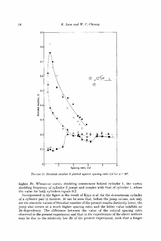
As a is increased to 30", the general trend for cylinder I remains the same as before but the Reynolds-number effects are significant a t l/d < 4.65 although the latter effects are not consistent, as can be seen in figure 11. The Reynolds-number effects for cylinders 2 and 3, are, on the other hand, negligible.
The Strouhal number for cylindcr 2 always remains a t or below 0.2. In particular, S rises from a value of 0.1 a t 1/11 = 1.27 to 0.2 a t 1/11 = 2.6. In then decreases again, but gradually, to a value of about 0.15 at 1/11 = 4.2, above which it increases to a value of 0.18. The trend for cylinder 3 is much more regular in that the Strouhal number decreases monotonically from a maximum value of 0.55 a t 1/11 = 1.27 to about 0.2 a t l/d > 3.0. The latter implies that the influence of cylinders 1 and 2 on cylinder 3 is negligible for a = 30" and 1/11 > 3.0.
When a is increased to 40°, the absolute values of S for cylinder 3 move closer to that for cylinder I , as can be seen in figure 12. Reynolds-number effects are detected for these two cylindcrs at l/d < 2.0. The effects on cylinder 2 are, however, negligible.

Vortex shedding and flow interference of three cylinders 17
Or------
2 3 4 5 Spacing ratio, I/d
FIGURE 10. Strouhal number S plotted against spacing ratio E/d for a = 20"
The value of S for cylinder 3 a t the respective spacing ratios becomes even closer to that for cylinder 1 at a = 50", figure 13, and they become almost identical a t a = 60°, figure 14. Again Reynolds-number effects are detected only for cylinders 1 and 3 over the spacing-ratio range smaller than 2. The variation of S with l / d for cylinders 1 and 3 a t 60" is quite as expected because, as stated in $4.1, the flows about these two cylinders are symmetrical about the main stream, hence yielding same flow pattern. The distinct kinks detected for cylinder 2 in the range 3.5 < l / d < 5.0 from a = 10" to 40" have smoothed out at a = 50" and 60" such that the curve becomes monotonically increasing with lid.
Figure 15 shows the variation of Strouhal number with spacing ratio for all three cylinders a t the angle of fully shielded flow such that cylinder 1 and cylinder 2 are 'nominally in tandem'. A jump in the value of S for cylinder 2 is clearly shown between the spacing ratio of 4.65 and 4.96 for the lower R e and 4.2 and 4.65 for the
18 K . Lam and W . C . Cheuny
r -
0.8
'* 0
0
I
2 3 4 5 Spacing ratio, Ild
FIGURE 1 1 . Strouhal number S plotted against spacing ratio l / d for a = 30".
higher Re. Whenever vortex shedding commences behind cylinder 1, the vortex shedding frequency of cylinder 2 jumps and couples with that of cylinder 1, where the value for both cylinders equals 0.2.
Incorporated in the figure is the result of Kiya et al. for the downstream cylinder of a cylinder pair in tandem. It can be seen that, before the jump occurs, not only are the absolute values of Strouhal number of the present results distinctly lower, the jump also occurs a t a much higher spacing ratio and the latter value exhibits no Re-dependency. The difference between the value of the critical spacing ratio observed in the present experiment and that in the experiments of the above authors may be due to the relatively low Re of the present experiment, such that a longer

Vortex shedding and flow interference of three cylinders 19
0.Z
0.'
0.t
0.:
@ i B E g 0.1
e SI
- 0 1
0.:
0.:
0.1
(
?\" 0
2 3 4 5 Spacing ratio, i /d
FIGURE 12. Strouhal number S plotted against spacing ratio l / d for a = 40"
formation region behind cylinder 1 is induced. The difference in the value of X is due largely to the interference effects of cylinder 3, although Reynolds-number effects may also contribute to it.
For the present investigation the critical spacing ratio a t which complete elimination of interference effects of neighbouring cylinders occurs is dependent on Reynolds number.
5. Numerical modelling The above experimental investigation forms an important physical basis for
numerical modelling. In this study, Martensen's surface-vorticity method was employed to simulate the potential flow around the three cylinders. Details of the method are described and discussed by Lewis & Porthouse (1983) and Lam (1987). To simulate boundary-layer separation as observed from the visualization study,

20 K . Lam and W . C. Cheung
0
0
0
0
r4 i 2 E S O
e rz
-
0.
0.
0
2 3 4 5 Spacing ratio, I/d
FIGURE 13. Strouhal number S plotted against spacing ratio l / d for a = 50".
vorticity elements of strength ~ y ( ~ S p ) } ~ dt were shed from the f90" positions of all cylinders a t each time step, where y(Sp) is the surface vorticity a t the point of separation. These vortices, once shed, become free vortices which can drift downstream under the influence of the free-stream velocity and the induction of surface-vorticity elements and other free vortices. During convection, vortices drifting too close to each other are combined to form a single larger vortex while vortices that drift across the solid boundary are eliminated. The free vortices first form vortex sheets behind the respective cylinders and then roll up into mature wake vortices behind each cylinder. The 'random walk' process adopted by Chorin (1973) and Lewis & Porthouse (1983) for the simulation of vortex diffusion was used initially. However the effect was found to be insignificant when realistic values of kinematic viscosity were used. It is thought that in the initial stage viscous diffusion may not play an important role in the stability of the vortex sheet. Instead, the background turbulence is more important for the instability of the free shear layer

Vortex shedding and $ow interference of three cylinders 21
0.6 -
0.5 -
@I
i B
5 0.4-
0, Gi
- s
0.3 -
0.2 -
0 \
< 2 3 4 5
Spacing ratio, Ild O1
FIGURE 14. Strouhal number S plotted against spacing ratio Z/d for a = 60"
that leads to the alternate shedding of mature vortices behind the cylinders. Therefore, while retaining the idea of a 'random walk', the positions of the free vortices were given a random movement due to turbulence by a radial distance r i = IU A t e in an angular direction 8, = 2nMi, where I = u'/U represents the turbulent intensity, and Pi, Mi are random numbers between 0 and 1. Since decay of vorticity by diffusion at the later stage would take too much computing time, the vortices were simply eliminated after convecting ten diameters from the rearmost cylinder.
The above computational experiments were carried out using a HP9836 c desk-top computer with colour graphics output so that the flow pattern can be observed a t each time step. Figure 16 shows the flow patterns produced by the vort,ex clouds, and figure 17 shows the lift and drag coefficients obtained by integration of the pressure distribution around the cylinders for a spacing ratio of 3.6.
Comparison with photographs (figures 4a and 4f, shows that the flow patterns agrcc reasonably well. The drag coefficient (C,, = 1.0) and the Strouhal number (S =

22 K . Lam and W . C. Cheung
o.6;----
1 2 3 4 5
Spacing ratio, lid
FIGITRE 15. Rtrouhal number 9 plotted against spacing ratio l / d at the 'angle of fully shielded flow '. Symbols as figure 8; ----, Kiya et al. (1980) a t Re = 1 . 6 ~ lo4.
01
0.23) evaluated from the time variation of the lift coefficient of cylinder 1 are quite close to the experimental results. It is hoped that with further refinements and modifications of the method and longer computing time, better correlation between numerical modelling and experimental results can be achieved. Hence the velocity field, pressure field, lift and drag coefficients of such complicated cylinder configurations can be predicted fairly easily and accurately, and so the work of taking lengthy and difficult experimental measurements can be reduced.
6. Conclusions Vortex-shedding-frequency measurements were made for three equal circular
cylinders in equilateral triangular arrangements with angles of incidence ranging from 0" to 60" (covering all possible orientations of such a configuration) and spacing ratios from 1.27 to 5.43. Strouhal numbers of 0.7 for a narrow wake and 0.1 for a wide wake were found to converge to around 0.2 when the spacing ratio reached 4.65, indicating that the effects of flow interference became negligible thereafter.
The results of the variation of frequencies and flow patterns are summarized in several figures. In particular, the following important features should be noted. The first is the intrinsically different flow regimes for inverted-T-(ol = 0") and T-shaped (a = 60") arrangements relative to the oncoming flow. The well-known bistable biased flow behind two side-by-side cylinders is fully suppressed for all the T

Vortex shedding and $ow interference of three cylinders 23
Main-stream flow
-- - - - . . . - a- ..
-- ,. r-- - _ - - . ._ -- - -
FIGURE 16. Numerical results for vortex clouds behind three cylinders at (a ) a = 0" and (b) 60" for a spacing ratio of 3.6.

24 K . Lam and W . C. Cheung
2 at a = 60".
arrangements. The upstream side-by-side cylinders generated two equal narrow near wakes with the same vortex-shedding frequencies followed by a wide near wake on the third cylinder with a low vortex-shedding frequency. In contrast, the inverted- T arrangement did not suppress biased flow. Apparently the wake of the upstream cylinder disturbed the flow around the side-by-side cylinders and made the near wakes of different size, especially for l / d < 2.29. The second prominent feature of the interference occurred for all slightly staggered inverted-T arrangements (a < a,). The well established rule for the interference of two staggered cylinders was that the upstream cylinder's near wake should be always narrow followed by a wide one behind the downstream cylinder. Owing to the presence of the third cylinder, this rule is consistently violated as seen in all photographs, and resulted in a drastic

Vortex shedding and flow interference of three cylinders 25
difference of Strouhal numbers between cylinders 2 and 3. The flow patterns switched to normality when the angle of incidence became greater than a,, which was below 30". The third prominent feature was that when two cylinders were exactly in a tandem arrangement, the third cylinder disturbed the flow symmetry and the downstream cylinder appeared not shielded by the upstream one. The angle, which has been termed the 'angle of fully shielded flow ' as, increased from 8" to 27" which correspond to spacing ratios of 1.27 to 4.65. Therefore the vortex shedding behind the upstream cylinder was not suppressed even at the smallest spacing tested. Finally, although Reynolds numbers apparently did not have any effect on the Strouhal numbers measured except on the length of the near wake, or on the critical spacing ratio, further investigations in the upper subcritical range of Reynolds numbers would be required to clarify the extent of the applicability of these measurements to such a Reynolds-number range. A detailed study on the relationship between the width of the wake and the shedding frequency is also recommended.
I n view of the complexity of flows around three circular cylinders, the numerical results obtained at this stage are quite promising. The discrepancies between the numerical and experimental results indicate that further refinements of the method are still required.
The authors wish to thank the Research Committee of the Hong Kong Polytechnic and the Head of Department of Mechanical and Marine Engineering for their support. Thanks are also due to Mr Y. P. Zhang of the Fluid Mechanics Laboratory and the technical staff of the Project Laboratory for assisting with the construction of the dye injection system and models.
REFERENCES
BARNES, F. H., BAXENDALE, A. tJ. & GRANT, I . 1986 A lock-in effect in the flow over two cylinders.
BAXENDALE, A. J., GRANT, I. & BARNES, F. H . 1985 The flow past two cylinders having different
BEARMAN, P. W. & WADCOCK, A. J. 1973 The interaction between a pair of circular cylinders
BLEVINS, R. D. 1977 Flow-induced Vibration. Van Nostrand Reinhold. BOKAIAN, A. & GEOOLA, F. 1984 Vortex shedding from two interfering circular cylinders. J . Engng
CHORIN, A. J . 1973 Numerical study of slightly viscous flow. J . Fluid Mech. 57, 785-796. HILL, R. S., SHIM, K . C. & LEWIS, R. I. 1986 Sources of excitation in tube banks due t o vortex
IGARASHI, T. 1981 Characteristics of flow around two circular cylinders arranged in tandem.
IGARASHI, T. & SUZUKI, K . 1984 Characteristics of the flow around three circular cylinders
KING, R. & JOHNS, D. J. 1976 Wake interaction experiments with two flexible circular cylinders
KIYA, M., ARIE, M., TAMURA, H. & MORI, H . 1980 Vortex shedding from two circular cylinders
LAKSHMANA GOWDA, B. H . & PRABHU, D. R. 1987 Interference effects on the flow-induced
LAM, K . 1987 Potential flow calculation by surface vorticity method and computer graphics.
Aero. J . April, 128-138.
diameters. Aero. J . April, 125-134.
normal t o a stream. J . Fluid Mech. 61, 499-511.
Mech. ASCE 110, 632-628.
shedding. Proc. Instn Mech. Engrs. 200, C4, 293--301.
J S M E 24, 323-331.
arranged in-line. J S M E 27, 2397-2404.
in flowing water. J . Sound Vib. 45, 259-283.
in staggered arrangement. Trans. A S M E I: J . Fluids Engng 102, 16G-173.
vibrations of a circular cylinder. J . Sound Vib. 112, 487-502.
Computer & Graphics 1 1, 3 5 4 7 .

26 K . Lam and W . C. Cheung
LAM, K. & CHU, K. H. 1986 Construction and performance of a recirculating water-tunnel system. Internal Rep. MMR-T-6. Ikpt. of Mech. and Marine Engng, Hong Kong Polytechnic, March .
LEWIS, R. 1. 1981 Surface vorticity modelling of separated flows from two-dimensional bluff bodies of arbitrary shape. J . Mech. Engng Sci. 23, 1-12.
LEWIS, R. 1. & PORTHOUSE, D. T. C. 1983 Numerical simulation of stalling flows by an integral equation method. In Viscous Effects in Turbomachines, Copenhagen, June , AGARD-CCP- 351.
M A R T E N S E N , E. 1959 Die Barechnung der Druckvertilungau dicken gitterprofilen mit hilfe von Fredholmschen integral-gleichungen. Arch. Rat. Mech. Ana l . 3, 235-237,
XOVAK, J . 1974 Strouhal number of a quadrangular prism, angle iron and circular cylinders arranged in tandem. Acta Tech., Czech. Acad. Sci. 3, 361-373.
I'AIUOUSSIS. M. P. 1979 Flow-induced vibrations in nuclear reactors and heat exchangers, practical experiences and state of knowledge. In Practical Experiences with Flow Induced Vibrations (ed. E. Naudaschar & D. Rockwell), pp. 1-80, Springer.
PA~DOVSSIS, M . P., MAVRIPLIS, I). & PRICE, S. ?J. 1984 A potential-flow theory for the dynamics of cylinder arrays in cross-flow. J . Fluid Mech. 146, 227-252.
PORTHOUSE, D. T. C. & LEWIS, R.-T. 1981 Simulation of viscous diffusion for extension of the surface vorticity method to boundary layer and separated flows. J . Mech. Engng Sci. 23,
PRICE, S. J . & PAIDOUSSIS, M. P. 1984 The aerodynamic forces acting on groups of two or three
SARPKAYA, T. & SCHOAFF, R. L. 1979 Inviscid model of two-dimensional vortex shedding by a
SAYERS, A. T. 1987 Flow interference between three equispaced cylinders when subjected to a
STANSBY, P. K. 1977 An inviscid model of vortex shedding from a circular cylinder in steady and
THOMAS, D. G. & KRAUS, K. A. 1964 Interaction of vortex streets. J . App l . Phys. 35,
TRIANTAFYLLOU, G. S., TRIANTAFYLLOU, M. S. & CHRYSSOSTOMIDIS, C. 1986 On the formation of vortex streets behind stationary cylinders. J . Fluid Mech. 170, 461477.
WILLIAMSON, C. H. K. 1985 Evolution of a single wake behind a pair of bluff bodies. J . Fluid Mech. 159, 1-18.
ZDHAVKOVICH, M. M. 1968 Smoke observation of the wake of a group of three cylinders a t low Reynolds number. J . Fluid Mrch. 32, 339-351.
ZDRAVKOVICH, M. M. 1977a Review of flow interference between two circular cylinders in various arrangement. Trans. A S M E 1: ,I. Fluids Engng 99, 618-633.
ZDRAVKOVICH, M. M. 1977 b Interference between two circular cylinders, series of unexpected discontinuities. J . Indust. Aerodyn. 2, 255-270.
ZDRAVKOVICH. M. M. 1985 Flow induced oscillations of two interfering circular cylinders. J . Sound
ZDRAVKOVICH. M. M. 1987 The effects o f interference between circular cylinders in cross flow.
157-167.
circular cylinders when subjected to a cross flow. J . Wind Eng. Indust. Aero. 17, 329-347.
circular cylinder. A Z A A J . 17, 1193-1200.
cross flow. J. Winds. Engng Ind . Aero. 26, 1-19.
oscillatory far flows. Proc. In s tn Giv. Engrs 63, 865-880.
3458-3459.
Vib. 101, 51 1-521.
J . Fluids Structures 1, 235-261.