PERI - Rail Climbing System RCS-Lite Formwork scaffold...
90
Edition 0 5 /20 10 Rail Climbing System RCS-Lite Formwork scaffold with carriage Assembly Instructions for Standard Configuration
Transcript of PERI - Rail Climbing System RCS-Lite Formwork scaffold...

Edition 05/2010
Rail Climbing System RCS-LiteFormwork scaffold with carriage
Assembly Instructions for Standard Configuration
2009-04 AI RCS Lite.pdf 14.04.2009 14:15:08 Uhr

2 / 65 Copyright PERI GmbH, Germany RCS-Lite
Content Introduction 41. Standard configuration ......................................................................................................... 4
1.1 General ....................................................................................................................................................41.2 Features...................................................................................................................................................4
2. Intended use........................................................................................................................ 53. Overview ............................................................................................................................. 6
3.1 Climbing Scaffold.....................................................................................................................................63.2 Mounting with climbing shoe...................................................................................................................7
4. Climbing Device and Hydraulics ........................................................................................... 94.1 Climbing device and hydraulic hoses .....................................................................................................94.2 Hydraulic Pump .....................................................................................................................................10
5. Operating Status and Loads............................................................................................... 115.1 Working Operations...............................................................................................................................115.2 Climbing Operations ..............................................................................................................................115.3 Non-Operational Status.........................................................................................................................115.4 Overview of Live Loads .........................................................................................................................11
6. Operating sequence........................................................................................................... 127. Safe working conditions ..................................................................................................... 13
7.1 General safety instructions....................................................................................................................137.2 Storage and transportation....................................................................................................................137.3 System-specific......................................................................................................................................14
Part A Work Preparation 16 A1 Planning the Climbing scaffold............................................................................................ 16
A1.1 System Dimensions...............................................................................................................................16A1.2 Bearing reactions...................................................................................................................................19
A2 Planning of the Platforms ................................................................................................... 20A2.1 General ..................................................................................................................................................20A2.2 Planking .................................................................................................................................................20A2.3 Platform girders .....................................................................................................................................21A2.4 Mounting of toe board ...........................................................................................................................23A2.5 Working platforms..................................................................................................................................24A2.6 Finishing platform ..................................................................................................................................25A2.7 Corner platforms....................................................................................................................................26A2.8 Platforms on circular structures ............................................................................................................27
A3 Guardrails.......................................................................................................................... 28A3.1 General requirements............................................................................................................................28A3.2 Guardrails with handrail boards ............................................................................................................28A3.3 Guardrails with scaffold tubes ...............................................................................................................28A3.4 Lateral guardrails ...................................................................................................................................29
A4 Planning Requirements...................................................................................................... 30A4.1 Position of Leading Anchor in the Ground Plan ...................................................................................30A4.2 Planning of the Climbing Sequence......................................................................................................30A4.3 Crane attachment ..................................................................................................................................31
Part B Assembly 34 B1 Pre-assembling the formwork ............................................................................................. 34
B1.1 Mounting the strongback to VARIO formwork ......................................................................................34B1.2 Mounting the strongback to TRIO formwork.........................................................................................35B1.3 Concreting platforms .............................................................................................................................36
B2 Assembly bracket unit ........................................................................................................ 37B2.1 Insertion of an additional spacer M20...................................................................................................38B2.2 Re-positioning of spacers M24 .............................................................................................................38
B3 Initial mounting procedure .................................................................................................. 39B4 Mounting the formwork....................................................................................................... 39B5 Concreting at first application ............................................................................................. 40B6 Initial Moving Procedure..................................................................................................... 40B7 Assembly of ladder access................................................................................................. 43

RCS-Lite Copyright PERI GmbH, Germany 3 / 65
Part C Application 44 C1 Standard Cycle Operations................................................................................................. 44 C2 Working with the formwork ................................................................................................. 46
C2.1 Operating the Carriage..........................................................................................................................46 C2.2 Adjusting the Formwork.........................................................................................................................46
C3 Assembly of Leading Anchor .............................................................................................. 47 C3.1 Mounting with Advancing Bolt ...............................................................................................................47 C3.2 Mounting with Anchor Positioning Stud ................................................................................................47
C4 Assembly and dismantling of the suspension unit................................................................ 48 C4.1 Mounting the suspension unit ...............................................................................................................48 C4.2 Dismantling the suspension unit ...........................................................................................................49 C4.3 Dismantling the Anchorage...................................................................................................................50
C5 Operating the climbing shoe............................................................................................... 51 C5.1 Opening and closing the Climbing Shoe ..............................................................................................51 C5.2 Locking the Climbing Pawl ....................................................................................................................51 C5.3 Activating the Climbing Pawl.................................................................................................................51
C6 Dismantling the climbing unit .............................................................................................. 52 Part D Moving the Climbing Unit 54 D1 Moving with the crane ........................................................................................................ 54
D1.1 Preparations ..........................................................................................................................................54 D1.2 Moving procedure..................................................................................................................................55
D2 Moving with the climbing unit .............................................................................................. 56 D2.1 Initial Operations....................................................................................................................................56 D2.2 Preparations ..........................................................................................................................................57 D2.3 Self-Climbing Procedure .......................................................................................................................58 D2.4 Self-climbing of the final climbing unit...................................................................................................62 D2.5 Solving malfunction problems ...............................................................................................................62 D2.6 Operating the oil hydraulic unit .............................................................................................................62 D2.7 Removing air from the hydraulic device ...............................................................................................62 D2.8 Hydraulic schemes ................................................................................................................................63
Part E General Information 64 E1 Cleaning and Maintenance................................................................................................. 64 E2 Transport........................................................................................................................... 64 E3 Storage.............................................................................................................................. 64 E4 Hydraulic System............................................................................................................... 65

4 / 65 Copyright PERI GmbH, Germany RCS-Lite
Introduction 1. Standard configuration
1.1 General These assembly instructions describe the standard configuration for RCS as formwork scaffold
• with only one finishing platform • with intermediate Climbing Shoes on each concreting section • self-climbing by means of Climbing Rail Extension 110 • Climbing Device RCS 50 to be installed from working platform
1.2 Features RCS-Lite is based on the RCS - Rail Climbing System with supplementary components.
The rail climbing system is a bracket-type framework construction and is designed as falsework, ac-cording to the provisions laid out in DIN EN 12812, for supporting wall formwork.
The climbing scaffold consists basically of 2 bracket units (climbing rails with platform beams and di-agonal struts) which are connected with the platforms (working platform and finishing platform) and scaffold tube bracing. Platforms consist of planking fixed to girders (GT 24 or VT 20 formwork girders). The platforms are pre-assembled on the cross-beams (working platform or finishing platform girders. Handrail posts and guardrail posts, with handrail boards or scaffold tubes attached, serve as safety barriers against falling.
The climbing formwork is formed by connecting the formwork and climbing scaffold by means of a SRU U120 strongback which can be moved either as a climbing unit using a crane (attachment point on the strongback) or as a self-climbing unit with an integrated hydraulic climbing mechanism. The self climbing mechanism has a lifting capacity of 50 kN and a stroke height of 50 cm. Accessories for at-taching the formwork serve for mounting VARIO and TRIO formwork systems
Strongbacks are fixed to the carriage and braced with formwork spindles. Through the approx. 90 cm gap created when retracting the formwork, there is an end-to-end free working area available.
The concreting platform is mounted to the formwork or the strongback.
For self-climbing the system with the hydraulic Climbing Device RCS additionally a climbing rail exten-sion 110 has to be installed on the top end of the climbing rail. This enables to install the climbing de-vice on the level of the working platform. Additionally intermediate climbing shoes are installed on the wall for proper guidance and support during the climbing sequence.
RCS-Lite Copyright PERI GmbH, Germany 5 / 65
2. Intended use 1. PERI products have been exclusively designed as technical work equipment for use in the indus-
trial and commercial sectors by suitably trained personnel. 2. These assembly instructions serve as a basis for the building-related risk assessment and the
instructions for the provision and use of the system by the contractor (user). However, this does not replace these.
3. Only PERI original components may be used. The use of other products and spare parts repre-sent a misapplication with associated safety risks.
4. The components are to be inspected before each use to ensure that they are in perfect condition as well as being able to function correctly.
5. Changes to PERI components are not permitted and represent a misapplication with associated safety risks.
6. Safety instructions and permissible loads must be observed at all times. 7. Components provided by the contractor must conform with the characteristics required in these
assembly instructions as well as all valid construction guidelines and standards. In particular, the following apply if nothing else is specified:
• Timber components: Strength Class C24 for Solid Wood EN 338.
• Scaffold tubes: galvanized steel tubing with minimum dimensions Ø 48.3 x 3.2 mm according to EN 12811-1:2003 4.2.1.2.
• Scaffold tube couplings according to EN 74.
8. Any deviations from the standard configuration may only be carried out after a separate risk as-sessment has been done by the contractor (user). On this basis, appropriate measures for the working safety and stability are to be implemented.

6 / 65 Copyright PERI GmbH, Germany RCS-Lite
3. Overview Abbreviations used: hB Storey height hG Utilization height above ground level hS Formwork height ö see other chapter
a Anchor distance to concrete joint b Width of influence of a bracket c Spacing of bracket axes in the ground plan xR Retraction way max. 90 cm
3.1 Climbing Scaffold Assembly of the climbing scaffold varies depending on the storey height, the formwork used and type of guardrail protection.
Fig. 1 : Use with VARIO formwork climbing condition
Fig. 2 : Use with TRIO formwork working condition
h S
h B
h B
hG
a h 2
h 1
11A
11B
11C
11D
4
8
9
7
6
10
18
19
18.2
18.1
20
20
20
xR
h B
h B
h S
hG
a h 2
h 1
3
5
2
1
14
16
17
18
18
8
15.3
15.1
15.2

RCS-Lite Copyright PERI GmbH, Germany 7 / 65
3.2 Mounting with climbing shoe
Fig. 3: Overview of mounting position
Overview of Mounting Position
2 Climbing Rail RCS 11 Climbing Shoe RCS, Item No. 109468 1) 12 Wall Shoe RCS, Item No. 109503 1) 13 Anchorage
Fig. 4: Wall shoe
Wall Shoe 1)
12 Wall Shoe RCS, Item No. 109503 1) 12.1 Hex. Bolt M30x70-8.8, Item No. 029420 1) 12.2 Locking Pin for Wall Shoe RCS 1) Anchorage version 1: with climbing cone 2 M30/DW20 Anchorage version 2: with Screw-On Cone M30/DW26
Fig. 5: Anchorage M30/DW20
Anchorage version 1: with climbing cone 2 M30/DW20
13.1 Climbing Cone 2 M30/DW20, Item No. 030920 1)
13.2 Tie Rod DW20, Item No. 030700 1) 2) or Tie Rod B20, Item No. 030745 1) 2) LS = hV − 77 mm
13.3 Threaded Anchor Plate 20, Ø 100 mm Item No. 030860 1) 2)
According to Building Authority Approval Z-21.6-1767
Important! With the tie rod B20 (with continuous thread), the load-carrying capacity of the anchorage can be less than the tie rod DW20 (with discontinuous thread)! See Building Authority Approval or corresponding product information.
Fig. 6: Anchorage M30/DW26
Anchorage version 2: with Screw-On Cone M30/DW26
13.4 Screw-On Cone M30/DW26, Item No. 057257 1)
13.5 Threaded Anchor Plate 26, Ø 120 mm Item No. 030870 1) 2)
According to Building Authority Approval Z-21.6-1766
1) all parts of the suspension and anchorage are safety components 2) embedded parts – not reusable
13 11
12
1
12
12.1
13
12.2
13.3 13.2 13.1
13.5 13.4

8 / 65 Copyright PERI GmbH, Germany RCS-Lite
Name Item. No.
1. Climbing Rail RCS 348 109470 2)
2. Climbing Rail RCS 148 114166 2)
3. Working Platform
3.1 Crossbeam RCS 220 109716
4. Climbing Rail Extension 110 113745
5. Finishing Platform
5.1 Finishing Platform Beam RCS 109722
6. Diagonal Strut RCS 212 110012 2)
7. Guardrail Post RCS 226 109720
8. Handrail Post RCS 384 109721
9. Climbing Rail Extension 100 109791
10. Climbing Rail Connector 79 113744
11. Climbing Shoe RCS 109468 1)
12. Wall Shoe RCS 109503 1)
13. Anchoring 1)
14. Scaffold Tube Bracing 2)
15. Strongback RCS as Steel Waler Universal SRU U120 2)
15.1 Waler Fixation U 100-120 110059
15.2 Adjusting Unit SRU, external 110400
15.3 Strongback Adapter RCS/SRU 115325
16. Formwork Spindle as Heavy Duty Spindle SLS 2)
17. Formwork VARIO or TRIO
18. Concreting platform and intermediate formwork platform
18.1 Platform Beam RCS/SRU 113 114301
18.2 Guardrail Post RCS/SRU 184 114328
19. Carriage RCS 109968 2)
20. Guardrails with Scaffold tubes or timber 1) Safety component 2) Part of the load-bearing system

RCS-Lite Copyright PERI GmbH, Germany 9 / 65
4. Climbing Device and Hydraulics
4.1 Climbing device and hydraulic hoses
Fig. 7: Climbing Device RCS
Fig. 8: Cylinder Base
21 Climbing Device RCS 50 1)
Details can also be found in the RCS Climbing Device operating instructions 21.1 Piston head with claw
21.2 Cylinder base
21.3 Return from the piston side with hydraulic quick-coupler (nipple) left + right 2)
21.4 Inflow to the piston base with hydraulic quick-coupler (bushing) left + right 2)
21.5 Reposition Device
21.6 Locking Lever
Due to the clear arrangement of the quick-couplers nipple (return) and bushing (inflow) on the climbing and hydraulic units, incorrectly con-necting the inflow and return lines is excluded.
Fig. 9: Hydraulic Twin Hose
22.1 Hydraulic Twin Hose RCS 10 m 3)
22.2 Hydraulic Twin Hose RCS 20 m 3)
22.3 Hydraulic Quick-Coupler (bushing)
22.4 Hydraulic Quick-Coupler (nipple)
1) Climbing devices are safety components 2) In order to prevent the quick-couplers colliding with
platforms or other parts of the climbing protection wall when climbing, there is the possibility of verti-cally arranging the couplings by means of angle pieces. è Contact PERI!
3) Hydraulic hoses are safety components
22.4
22.3
22.122.2
22.3
22.4
L
21.3
21.2
21.5
21.6
21.4
21
21.1
21.2 21.4
21.3

10 / 65 Copyright PERI GmbH, Germany RCS-Lite
4.2 Hydraulic Pump
Fig. 10: Hydraulic Pump
Fig. 11: Hydraulic Oil Tank
Fig. 12: Hydraulic Unit Connections
23 Hydraulic Pump RCS 4 x 190 bar, 380-460V 1) for 4 climbing devices
Details can also be found in the operating instructions for the RCS Climbing Device
23.1 Operating lever
23.2 Switch unit
23.3 Electricity socket with phase inverter
23.4 Hydraulic oil tank
23.5 Filling piece
23.6 Oil level indicator
23.7 Oil filter
23.8 Return from the piston side of the cylinder with hydraulic quick-coupler (bushing)
23.9 Inflow for the piston head side of the cylinder with hydraulic quick-coupler (nipple)
23.10 Rotary field control lamp
Accessory for power supply with CEE socket operational voltage 380-400V/16A, 50Hz:
24.1 Adapter Cable RCS
Accessory for assembly of adapter cable, operational voltage 380-400V, 50-60Hz:
24.2 Plug Socket RCS, black
1) Hydraulic pumps are safety components
23.8
23.9
23.2
23.3 24.1 24.2
23.10
23.1
23.4
23.5
23.6
23.7
23 23.4
23.1
23.2
23.5
23.3

RCS-Lite Copyright PERI GmbH, Germany 11 / 65
5. Operating Status and Loads
5.1 Working Operations • Cleaning the formwork, reinforcement for the wall, closing the formwork, concreting and
striking, inspection and maintenance • Platforms are freely accessible for the required work to be carried out. • Formwork is moved forward and retracted on the carriage. • Max. wind speed 72 km/h (wind impact pressure q = 0.25 kN/m²) • Loads are to be evenly distributed. One-sided loads on cantilevered platform areas are not
permitted without adequate measures against uplift at the opposite bracket!
5.2 Climbing Operations • Moving the climbing unit by crane or by means of the hydraulic climbing mechanism • The formwork is retracted on the carriage. • Non-planned loads on the platform are to be removed • Climbing by crane:
personnel are not allowed on the platforms during the climbing procedure • Self-climbing:
personnel required for the climbing procedure are usually on the adjacent platforms. When climbing the last platform in a cycle or if manual adjustments are required during the self climbing procedure, accessing the platform to be climbed is necessary.
• Max. wind speed 64 km/h (wind impact pressure q = 0.2 kN/m²) The climbing position has to be structurally verified, as this can be decisive.
5.3 Non-Operational Status • During longer work breaks, overnight, storm warnings, with wind speeds over 72 km/h • Accessing the platforms during storm conditions is forbidden • The formwork is moved on the carriage into the concreting position • Materials and other equipment can be left on the working platform • The resulting wind speed (wind impact pressure) for storm conditions depends on utilization
height, wind zone and terrain category according to DIN 1055 or EC 1. Equivalent values based on the relevant local wind load standard can be chosen accordingly.
• If given limits are exceeded, a visual inspection of all bearing parts and a functional check of all safety-related parts are required for further use.
• If a storm warning has higher wind speeds than originally stated, the site management is to be informed, all enclosure tarpaulins are to be removed and the scaffold can be climbed down to the previous floor but only on the instructions of authorized site personnel. Materials and other equipment are to be removed from the platforms.
5.4 Overview of Live Loads Table 1: Live Loads
Working Procedure Platform
Reinforce-ment Cleaning Concreting Preparation
Climbing Non-operational
Concreting platform 75 kg/m² 150 kg/m² Working platform 300* kg/m² 150 kg/m² 150 kg/m² 75 kg/m² 100 kg/m² Finishing platform 150 kg/m² 150 kg/m² Max. wind speed 72 km/h 64 km/h specified
Carriage Retracted or in concreting position Retracted concreting position
* The maximum live load for working platforms can be reduced to 200 kg/m² (specified)
The bearing structure has to be verified for these loads and conditions with a structural analy-sis according to PERI product information.

12 / 65 Copyright PERI GmbH, Germany RCS-Lite
6. Operating sequence
Mounting on 1st casting segment. Place formwork, reinforce and concrete 2nd section. Strike formwork.
Mount Climbing Shoes, assemble Climbing Rail Extension and install Climbing Device. Attach finishing plat-form.
Climbing to 2nd section. Climbing rail Extension leads into Climbing Shoe. Recover lower anchor.
Fig. 13: Initial use
Place formwork, reinforce and concrete standard section. Strike formwork.
Recover lower Climbing Shoe, mount upper Climbing Shoe. Assemble Climb-ing Rail Extension and install Climbing Device. Self-climbing of the climbing unit.
Interrupt climbing sequence for mount-ing and recovering next Climbing Shoes. Dismantle Climbing Rail Extension in final position.
Fig. 14: Standard cycle

RCS-Lite Copyright PERI GmbH, Germany 13 / 65
7. Safe working conditions The structures shown in these assembly instructions are examples and feature only one component size. They are valid accordingly for all component sizes contained in the standard configuration.
7.1 General safety instructions 9. Deviations from the standard configuration and/or intended use present a potential safety risk. 10. All country-specific laws, standards and other safety regulations are to be taken into account
whenever our products are used. 11. During unfavourable weather conditions, suitable precautions and measures are to be taken in
order to ensure both working safety and stability. 12. The contractor (user) must ensure the stability during all stages of construction. He must ensure
and verify that all loads which occur are safely transferred. 13. The contractor (user) has to provide safe and secure working areas which can be safely ac-
cessed. Areas of risk must be cordoned off and clearly marked. Hatches and openings on acces-sible working areas must be kept closed during working operations.
14. For better comprehensibility, detailed drawings are partly incomplete. The safety installations which have possibly not been featured in these detailed drawings must nevertheless be available.
7.2 Storage and transportation 1. Do not drop the components. 2. Store and transport components so that no unintentional change in their position is possible. De-
tach lifting gear from the lowered units only if these are in a stable position and no unintentional change is possible.
3. When moving the components, make sure they are lifted and set down so that any unintentional tilting over, falling apart, sliding or rolling away is avoided.
4. Use only suitable load-carrying equipment to move the components as well as using the desig-nated load-bearing points.
5. During the lifting and moving procedure, ensure all loose parts are removed or secured. 6. During the moving procedure, always use a guide rope. 7. Move components on clean, flat and sufficiently load-bearing surfaces only.

14 / 65 Copyright PERI GmbH, Germany RCS-Lite
7.3 System-specific safety instructions 1. The contractor has to ensure that assembly, adjusting and dismantling, moving as well as correct
use and handling of the product is supervised by trained and authorized personnel. 2. All persons working with the product must be familiarized with the working and safety instructions. 3. The contractor must ensure that the assembly instructions, other relevant operational and assem-
bly documentation, all required plan documents, parts lists and other data are at the user’s dis-posal.
Assembly work
4. The contractor has to make sure that appropriate and sufficient tools, lifting equipment and acces-sories, a suitable and adequately-sized area for assembly and storage, as well as enough crane capacity are available for the user.
5. During assembly work, unexpected dangerous situations can always arise – the level of which is to be determined on an individual basis and, if necessary, measures are to be taken that will eliminate or at least reduce the risk to a minimum.
6. If guardrails cannot be used due to technical reasons or they have to be removed, other equip-ment must in place for catching any person falling to the ground. If the use of catching equipment should be inappropriate, then a safety harness (personal protection equipment) can be used, if suitable attachment points are available.
7. Use guide rope for better control of the assembly units when being moved by crane. 8. Avoid working under the path of loads being moved by crane. If this is not possible, suitable
measures are to be determined and implemented. Site personnel must avoid remaining between suspended loads and the building.
9. Personnel must keep away from the area below where assembly work is being carried out if the area at risk is not protected from falling objects. This area is to be clearly cordoned off.
Maintenance and repairs
10. Climbing scaffold components are to be checked before every use to make sure they are in satis-factory condition. Basically, all materials used must be in perfect condition.
11. Platforms are to be inspected by authorized personnel at regular intervals for any signs of dam-age. Dirt and concrete surplus which can impair the functionality must to be removed immediately. Damaged construction components are to be identified, removed and replaced.
12. If the maximum permissible wind speed is exceeded, temperatures are beyond usual limits or after unusual events such as fire or earthquakes, all safety-related parts and the load-bearing system itself are to be checked for function and bearing capacity before being used.
Safety components: • Visual inspections by authorized personnel at regular intervals • Function control to be carried out before every climbing sequence and assembly by qualified
personnel • Parts are to be replaced only with PERI original components. • Repairs must be carried out by PERI-trained personnel only • In cases of overloading or recurring damage, stop work on and under the platforms, determine
and stop the cause. Load-bearing system: • Visual inspection to be carried out by authorized personnel before the first use • Only PERI original parts to be used for repairs or exchange • In cases of overloading or recurring damage, stop work on and under the platforms, determine
and stop the cause. Other components: • Repairs to be carried out by qualified personnel and site management is to be informed • In cases of recurring damage, determine and stop the cause.

RCS-Lite Copyright PERI GmbH, Germany 15 / 65
Access
13. Safe access to working areas must be provided at all times. 14. Gangways, stairs, stair towers or lifts are the preferred methods. Ladders are suitable only in ex-
ceptional cases. 15. Internal scaffolding ladders must not connect more than 2 scaffolding levels and have to be offset.
Safety must be ensured by mounting suitable equipment such as guardrails or netting on the out-side edge of the scaffold.
16. All access hatches and openings in accessible areas of the scaffold must be fitted with appropriate equipment to prevent accidents. Hatch covers must be closed every time after use.
17. In the case of an emergency situation, the working areas must have escape routes or suitable rescue equipment available. It must also be ensured that at least one escape route or set of res-cue equipment is still usable if power supplies are cut off.
Protection against falling objects
18. Work must not take place at the same time on areas directly on top of each other, if the lower working and access areas are not protected against falling objects such as tools and materials.
19. Access and working areas in dangerous positions are to be avoided. If this is not possible due to working procedures, suitable safety equipment must be in place. This also applies to work of short duration.
20. High working positions must be secured with suitable netting (mesh size max. 2cm), stretching below the working area from the top edge of the guardrail and fixed as close as possible to the building edge. The gap between the building and netting may not exceed 5 cm. Alternatively, the scaffold decking at high working positions can be placed close to the building and multi-part guardrails can be replaced by a solid protective wall.
21. Lower-positioned working areas must have appropriate protective cover along the entire length of the area at risk.
22. Ensure that tools and materials are not at risk of falling off the working area. Remove concrete surplus and other evidence of dirt at regular intervals. In general, the platforms are to be kept clean.
Climbing procedure
23. Strike formwork only when the concrete has sufficiently hardened and site management has given the go-ahead. Mounting the climbing units for the next concreting step can only take place after the required concrete strength has been achieved.
24. When platforms are being moved, unprotected edges are created between the individual platforms which present a safety risk. Such affected areas are to be cordoned off!
25. No persons, building materials or tools may be transported on the platforms when being moved by crane. Exceptions are permitted due to an operational work and assembly instruction which is in line with a required risk analysis.
26. When climbing by means of the hydraulic climbing device, details regarding the arrangement of the hydraulic hoses must be considered. If a standard arrangement is not possible, then a safe al-ternative is to be determined by a designated authorized person.
27. In the event of a malfunction, the platform is to be set down in the next possible position, person-nel are to leave the climbing unit using a safe access point and site management are to be in-formed immediately!
Additional PERI product information
Assembly instructions (e.g. for formwork systems VARIO or TRIO) Operating instructions (e.g. for Climbing Crossbeam 10t) PERI PI – separate product information (e.g. for perm. anchor loads) PERI design tables

16 / 65 Copyright PERI GmbH, Germany A1
Part A Work Preparation A1 Planning the Climbing scaffold
A1.1 System Dimensions
Fig. 15: Typical arrangement for storey height
hB = 3.00 up to 3.60 m Fig. 16: Typical arrangement for storey height
hB = 3.60 up to 4.00 m
Storey heights hB < 3.50 m (h1 < 1.50 m) When recovering the lower climbing shoe during the climbing sequence, the installed climbing rail extension must have reached the leading climb-ing shoe. Possibly it is required to position the finishing platform lower by means of the climbing rail extension 100. öFig. 17 and öC1, Fig. 70
h 1

A1 Copyright PERI GmbH, Germany 17 / 65
General requirements:
Additional intermediate Climbing Shoe RCS for each concreting section.
Regular cycle:
Minimum storey height: hB ≥ 3.00 m Maximum storey height: hB ≤ 4.50 m For storey heights > 4.00 m the finishing platform has to be suspended with additional cClimbing Rail extensions 100 Deviating storey heights require a detailed climb-ing sequence examination. For storey heights hB > 4.50 m demand other configuration of climbing rails and finishing plat-forms. Structural height of bracket for working and storm conditions: h0 = hB (distance of tension and compression point)
Self-climbing:
Minimum requirement for using the hydraulic Self-Climbing Device RCS 50: Distance of between Climbing Shoes where Climbing Device located: ∆h ≥ 2.00 m Assembly of Climbing Rail Extension 110 for installation of Self-Climbing Device RCS 50 from working platform.
Fig. 17: Typical arrangement for storey height hB = 4.00 up to 4.50 m

18 / 65 Copyright PERI GmbH, Germany A1
Anchoring and Starter Height
Fig. 18: Starter height with VARIO Fig. 19: Starter height with TRIO
This measurements result from: • Requirement for proper formwork fixation and adjustment. • Functionality of first self-climbing sequence. • Attaching and pulling of pre-assembled finishing platform.
The climbing rail has to be blocked off the wall at its base with timber (width 15 cm).
Table 2: System dimensions depending on the formwork
VARIO TRIO
Anchor spacing a 40 cm 50 cm Length of the top climbing rail Starter height min. hB
3.48 m 3.60 m 3.70 m

A1 Copyright PERI GmbH, Germany 19 / 65
A1.2 Bearing reactions The bearing reactions which act on the anchors and the building itself are to be taken from project-specific calculations. The maximum bearing reactions are to be shown on the general arrangement drawings. For all important load cases, the anchors, load application on the concrete and the transfer of forces into the building must be statically verified.
Fig. 20: Version 1: Vertical support on top
climbing anchor
Fig. 21: Version 2: Vertical support on interme-
diate climbing anchor
Version 1:
To insure proper installation of the self-climbing device the standard vertical support is located on the top climbing anchor 13A. The climbing anchor 13A has to be verified for interaction of the forces H1 and V1. This can be decisive for the platform size.
Version 2:
To ensure maximum capacity of the climbing anchors the vertical support can be located on the intermediate climbing anchor 13B. The climbing anchor 13A has to be verified for pure tension H1 and anchor 13B for pure shear force V1. For self-climbing operation the given dimensions have to be considered and addition-ally after the first stroke the vertical support has to be changed to the top anchor.
-H3
H1 V1
13A
13B
13C
-H3
H1
V2
13A
13B
13C

20 / 65 Copyright PERI GmbH, Germany A2
A2 Planning of the Platforms
A2.1 General
The construction of the platform decking must be done professionally and according to valid safety regulations.
The materials used must be of good quality.
Tripping hazards, unnecessary recesses and gaps in the decking are to be avoided or covered.
The distance between the lowest decking and the building can be up to a maximum of 5 cm.
The gap between individual planks can be up to a maximum of 2 cm.
The distance to the decking of adjoining platforms can be a maximum of 2 cm. Larger gaps are to be covered with firmly fixed boarding or by means of safety netting with a maximum mesh size of 2 cm.
Openings in the decking which are necessary for the work purposes must have correctly-fitted covers which remain in position.
Safe working conditions for all anchor points are made possible by the positioning of finishing plat-forms.
A2.2 Planking
Planking on the working platform
Load Class 4 working scaffold – maximum load 300 kg/m² according to DIN EN 12811-1
Timber planking according to strength class C24 for Solid Wood EN 338: Minimum dimensions w × d = 24 × 4.0 cm or 20 × 4.5 cm If less than 45 mm planking thickness, then we recommend to connect the single planks at the cantilever and in the middle of the span crosswise with a screwed timber min. w × d = 12 x 4 cm. Alternative: Solid Wood Strength Class C16 – EN 338: Minimum dimensions of the planking w × d = 24 × 5 cm
For use as safety scaffold for heights up to 3.00 m, a double layer of planking w × d = 24 × 5 cm is required – see DIN 4420-1.
Planking on the finishing platforms
Load Class 2 working scaffold – maximum load 150 kg/m² according to DIN EN 12811-1
Timber planking according to strength class C24 for Solid Wood EN 338: Minimum dimensions w × d = 20 × 4 cm If less than 45 mm planking thickness, then we recommend to connect the single planks at the cantilever crosswise with a screwed timber min. w × d = 12 x 4 cm.
Alternative: Solid Wood Quality Strength Class C16 – EN 338: Minimum dimensions of the planking w × d = 24 × 5 cm
Attention: When using planking with a lower strength class or dimensions or plywood sheets, a separate struc-tural verification is required!
Fig. 22: Attaching the planks
Mounting the planking
Fix each individual plank 3.6 using TORX 6x80 3.15 (2x) – e = 120 mm to each girder 3.5 it crosses.
Attention: Cantilevered planks and their girders are to be appropriately se-cured against lifting! For cantilevers larger than that specified, static verification is required!
3.6
3.15
3.5

A2 Copyright PERI GmbH, Germany 21 / 65
A2.3 Platform girders
Design of platform girders
Permissible spans and cantilevers of platform girders for working and finishing platform see separate product information. Possibly an additional buckling prevention of the working platform girders is required
Platform stiffening
Diagonal planking min. w × d = 4 x 20 cm is screwed to the underside of the platforms
Fixed with 2 TORX 6x80 per plank
Fixation of platform girders
Fig. 23: Mounting of girder
Working platform: rear
Cross Beam U160 RCS 3.1 Girder (here GT24) 3.5 Double girders:
Mounted with F.H. Bolt M8x200 MU + Washer 3.9 (2x) Optionally for securing against uplift: TORX 6 x 60 3.8 (2x) Single girders:
Mounted with F.H. Bolt M8x200 MU + Washer 3.10 (2x) Optionally for securing against uplift: TORX 6 x 60 3.8 (1x) Attention: F.H. bolts M8 are to be pre-drilled with Ø8. In case of VT 20 use lower drill hole in the cross beam for top chord.
3.1
3.9
3.8
3.5
3.1
3.8
3.5 3.10

22 / 65 Copyright PERI GmbH, Germany A2
Fig. 24: Mounting of girder
Working platform: front
Cross Beam U160 RCS 3.1 Girder (here GT24) 3.5 Cross beam head RCS/VARIO 3.2:
Mounted with F.H. Bolts M8x200 MU + Washer 3.9 (2x) Optionally for securing against uplift: TORX 6 x 60 3.8 (2x) Attention: F.H. bolts M8 are to be pre-drilled with Ø8. In case of VT 20 use lower drill hole in the cross beam for top chord.
Fig. 25: Mounting of girder
Finishing platforms
Platform Girder 4.1 Girder (here GT24) 4.2 Single girders:
Mounted with Hex. Wood Screws 8 x 80 DIN 571 4.5 (4x) alternatively with TORX 6x80 Double girders:
Mounted with F.H. Bolts M8x200 MU + Washer 4.6 (2x) Attention: F.H. bolts M8 are to be pre-drilled with Ø8.
3.1
3.9
3.8
3.5
3.2
4.5
4.2
4.1
4.6
4.2
4.1

A2 Copyright PERI GmbH, Germany 23 / 65
A2.4 Mounting of toe board
Fig. 26: Mounting of toe board
Requirements: Toe boards made of solid wood C24 (coniferous wood S10) Minimum dimensions w/d = 3/15cm Figure: working platform planking 3.6 Mounting – Alternative 1:
Mounting of toe board 3.7 with timbers 6/6 cm 3.13 TORX 6x80 3.14 SPAX 6x100 3.15 Screws fixed at 50 cm spacing Mounting – Alternative 2:
Mounting of toe board with reinforced steel angle bracket 90x90x2.5 3.11 TORX 6x40 3.12 (8x) Screws fixed at approx. 100 cm spacing
3.7
3.6
3.13
3.15
3.14
d
b
3.7
3.6
3.11
3.12

24 / 65 Copyright PERI GmbH, Germany A2
A2.5 Working platforms
Opening for foldable hatch
Opening in decking 57 x 72 cm Supported with timber 120/40 mm Fixed to lateral continuous planks with F.H. bolts DIN 603 M8x125 3.10 (min. 4x)
Fig. 27: Working platform
3.10
3.10

A2 Copyright PERI GmbH, Germany 25 / 65
A2.6 Finishing platform
Fig. 30: Finishing platform
Plywood cover 5.7 on the finishing platform pre-vents small objects from falling to the ground and simplifies dismantling after construction work has been completed. It is simply screwed on to the finishing platform decking when work is required to take place using the scaffold.
Fig. 28: Plywood cover Version 1
Opening for Climbing Rail (UU200)
Fig. 29: Plywood cover Version 2
Opening for Climbing Rail Extension 100 (UU100) To avoid cutting of girders GT24 for adjustment use double girders and shift to reach the exact plat-form length.
5.7
5.7

26 / 65 Copyright PERI GmbH, Germany A2
A2.7 Corner platforms
Mount the decking on the corner and internal platforms in such a way that they do not obstruct the climbing procedure, and that problem-free access from one platform to another is also possible when the formwork is retracted.
x1
Fig. 31: Mitered corner platforms
Version 1: mitered platforms
The platforms are mitered up to the wall-side girder. Lateral guardrails are attached between the deck-ing girders on the front side öA3.4 Ensure that there is a minimum passage width x1 of approx. 50 cm.
x3
x2
Fig. 32: Corner platform with overhang
Version 2: One platform with overhang
One platform is positioned up to the corner. The other platform must overlap sufficiently so that there is adequate passage width between the guardrails and formwork when the formwork is retracted. Platform overhang x2 Formwork thickness + retraction distance x3 Passage width x2 – x3 ≥ 50 cm Attention: In order to maintain the permissible cantilever of the platform girders (öA2.3), the distance of the bracket to the corner is to be minimized for over-lapping platforms. Please note – a more exact static verification of the anchors could be required!
Note: shaded areas = retracting areas for the formwork elements

A2 Copyright PERI GmbH, Germany 27 / 65
A2.8 Platforms on circular structures
Fig. 33: Parallel bracket arrangement
12.3
11
13
Fig. 34: Turnable wall shoe
Parallel bracket arrangement
With guided climbing formwork, brack-ets are to be arranged in a parallel fashion on circular structures in order to ensure the functionality of the form-work carriage.
The turnable wall shoe 12.3 can be used in order to connect the climbing shoe 11 with the anchoring 13. It compensates for twists of up to α = 15° between the axes of the anchors and the scaffold bracket. For such applications, separate static verification is required for the wall shoe and the anchoring. Minimum radius for use of the turnable wall shoe depending on the anchor spacing c:
( ) c215sin2
cR ×≈°⋅
≥
Fig. 35: Radial bracket arrangement
Radial bracket arrangement
As the formwork cannot be moved to the rear on the formwork carriage with radial arranged climbing brackets, either the formwork has to be removed for installation of the top climbing shoe or it has to be installed after climbing underneath the formwork. In addition, special measures for at-taching decking girders along with the installation of scaffold tube bracing have to be undertaken.

28 / 65 Copyright PERI GmbH, Germany A3
A3 Guardrails
A3.1 General requirements
Fig. 36: Guardrails
Guardrails must be fitted according to valid safety regulations! Guardrails must be fitted to all open platform edges at all levels. Netting or solid boarding to handrails to be used to prevent objects falling from the platforms. The following can be used as guardrails:
• Handrail boards • galvanized steel scaffold tubes Ø48.3 or Ø60.3 • timbers with enclosure made of
netting, tarpaulin, plywood or profiled sheeting Toe board, öA2.4
A3.2 Guardrails with handrail boards
Fig. 37: Guardrails with handrail boards
Requirements: Handrail boards 20.1 made of solid wood C24 (coniferous wood S10) Dimensions w/d = 3/15, 4/12 or 5/12 cm or with corresponding static verification, fixed on inner side with 50 cm spacing Mounting: F.H. bolts DIN 603 M8x70 MU 20.4
A3.3 Guardrails with scaffold tubes
Fig. 38: Guardrails with scaffold tubes
Requirements: Steel scaffold tubes 20.2 minimum quality St37-2 Dimensions Ø × t = 48.3 × 3.2 or 60.3 × 4.5 mm inner side, with netting or tarpaulin also on the outer side 50 cm spacing Mounting: clamp A64 DIN 3570 20.5 Hex. nut ISO 4032 M12-8 20.6 (2x)
20.4
20.1
20.520.6
20.2
≤ 8 cm
≥ 10
0 cm
≤ 47
cm
≤
47 c
m
≥ 15
A3 Copyright PERI GmbH, Germany 29 / 65
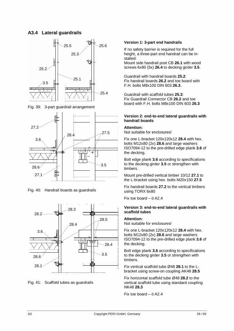
A3.4 Lateral guardrails
Fig. 39: 3-part guardrail arrangement
Version 1: 3-part end handrails
If no safety barrier is required for the full height, a three-part end handrail can be in-stalled: Mount side handrail post CB 26.1 with wood screws 6x80 (5x) 26.4 to decking girder 3.5. Guardrail with handrail boards 25.2: Fix handrail boards 26.2 and toe board with F.H. bolts M8x100 DIN 603 26.3. Guardrail with scaffold tubes 25.3: Fix Guardrail Connector CB 26.2 and toe board with F.H. bolts M8x100 DIN 603 26.3
Fig. 40: Handrail boards as guardrails
Version 2: end-to-end lateral guardrails with handrail boards
Attention: Not suitable for enclosures!
Fix one L-bracket 120x120x12 28.4 with hex. bolts M12x80 (2x) 28.6 and large washers ISO7094-12 to the pre-drilled edge plank 3.6 of the decking.
Bolt edge plank 3.6 according to specifications to the decking girder 3.5 or strengthen with timbers.
Mount pre-drilled vertical timber 10/12 27.1 to the L-bracket using hex. bolts M20x150 27.5
Fix handrail boards 27.2 to the vertical timbers using TORX 6x80
Fix toe board – öA2.4
Fig. 41: Scaffold tubes as guardrails
Version 3: end-to-end lateral guardrails with scaffold tubes
Attention: Not suitable for enclosures!
Fix one L-bracket 120x120x12 28.4 with hex. bolts M12x80 (2x) 28.6 and large washers ISO7094-12 to the pre-drilled edge plank 3.6 of the decking.
Bolt edge plank 3.6 according to specifications to the decking girder 3.5 or strengthen with timbers.
Fix vertical scaffold tube Ø48 28.1 to the L-bracket using screw-on coupling AK48 28.5
Fix horizontal scaffold tube Ø48 28.2 to the vertical scaffold tube using standard coupling NK48 28.3
Fix toe board – öA2.4
28.5 28.2
28.3
28.1
3.6
28.4
28.6 3.5
28.4
27.5 27.2
27.1
3.628.4
3.5 28.6
25.5
25.3
25.2
25.1 3.5
25.4
25.6

30 / 65 Copyright PERI GmbH, Germany A4
A4 Planning Requirements
A4.1 Position of Leading Anchor in the Ground Plan
Fig. 42: Standard leading anchor fixation
VARIO: There should be sufficient space between the anchor axis and adjacent formwork girders (hori-zontal 3 cm) so that the leading anchor 13 can be mounted to the advancing bolt 13.6. TRIO: There should be sufficient space between the anchor axis and the formwork struts (horizontal 3 cm, vertical 4 cm) so that the leading anchor can be mounted to the advancing bolt.
Fig. 43: Leading anchor fixation at formwork
struts
If the anchor position collides with struts of the TRIO formwork, then the Anchor Positioning Stud M30 13.7 instead has to be fixed with nails 30x80 on the formlining.
A4.2 Planning of the Climbing Sequence During planning as well as compiling work instructions for the climbing sequence, the following points must be considered: • Special attention is to be paid to the corner area assembly of the trailing platforms so that there is
safe access from one climbing unit to the next and the Hydraulic Pack can be moved safely. For this, the transition areas must be wide enough and without steps.
• Especially on corner and internal platforms, the decking must be designed so that it does not col-lide with the platforms or formwork of adjacent climbing units during the climbing procedure.
• Gangways and ladder access are planned in such a way so that safe entry to all climbing units is guaranteed at all times.
• Planning the climbing sequence includes operations around the whole building. This includes de-termining suitable positions for the hydraulic hoses and climbing the last climbing unit.
• A hydraulic plan shows how the climbing units are connected to the hydraulic hoses on the hy-draulic aggregate.
• Suitable measures are to be specified regarding the erection of barriers or other safety equipment on open edges.
13.7 13
13
13.6

A4 Copyright PERI GmbH, Germany 31 / 65
A4.3 Crane attachment
Fig. 44: Timber brace between strongbacks
The size of climbing units can also be restricted by the permissible load of the attachment point on the strongback. In this respect, for platforms of primary importance the weight has to be deter-mined during the planning stage. Also when as-sembling and dismantling climbing units, which are moved with the self-climbing device, the per-missible load of the attachment points must be taken into consideration. The weight of each climbing units is to be speci-fied in the general arrangement drawings.
Fig. 45: Section through timber brace
Crane operation without spreader beam
• Attachment of a timber 15.5 as compression brace at the top end of the strongback 15. For proper positioning the timber can be fixed to the concreting platform.
• Crane attachment point crane eye BR 2.5t 15.7 fixed with spacer for platform beam 15.6 to the top end of the strongback 15.
Note: Load capacity per crane eye max. 2500 kg with max. e = 25 cm Permissible weight of platform see Table 3
Table 3: Crane sling angle and permissible weight of symmetric climbing units
Permissible weight of the climbing unit Crane sling angle α
c ≤ 3,00 m c ≤ 4,00 m c ≤ 5,00 m
15° 5000 kg * 5000 kg * 5000 kg *
20° 5000 kg * 4400 kg 3730 kg
25° 4240 kg 3440 kg 2910 kg
30° 3490 kg 2780 kg 2350 kg * The crane eye BR 2,5t is decisive
An alternative attachment point with higher load-bearing capacity can be used (planning and static verification are required).
15.5
15
15.7 15.6
e
G
α α
c
15.5
15.1
15.7

32 / 65 Copyright PERI GmbH, Germany A4
Fig. 46: Application of Climbing Crossbeam
Crane operation using Climbing Crossbeam RCS 10t as spreader beam
Adjustment and application of Climbing Crossbeam RCS 10t 28 see according instructions for use • Attachment point:
Spacer for Platform Beam 15.6 inserted in hole at top end of the strongback 15 Load capacity max. 5000 kg
Notes: The attachment of a timber as compression brace is not necessary.
One chain of the Climbing Crossbeam RCS 10t has the option to be adjusted for locating the crane hook above the centre of gravity. So even non-symmetric platforms can be moved hanging horizontally.
28
15.6
15

A4 Copyright PERI GmbH, Germany 33 / 65

34 / 65 Copyright PERI GmbH, Germany B1
Part B Assembly B1 Pre-assembling the formwork
B1.1 Mounting the strongback to VARIO formwork
Fig. 47: Strongback Connector SRU
Fig. 48: Height Adjusting Unit SRU
• Position strongback on the waler of the formworkaccording to planning specifications.
• Tension the strongback SRU U120 15.1 on walerof the formwork 17 with the help of the waler fixa-tion SRU 15.2.
• Pull the height adjusting unit SRU 15.3 over thelower end of the strongback.
• Fix upper part of the adjusting unit in the strong-back with bolts Ø20.
• Spindle lower part with the adjustment bolt SW30 until touching the waler flange. Waler flangenow lies on the jaws of the height adjustment uniton both sides.
• Fine adjustment of the strongback position.
Note: Formwork weight per SRU height adjustment unit: 1200 kg
Attention: When using TRIO formwork, steel walers are to be clamped on the formwork elements for connection with strongback. In this respect, ensure that there is a load-bearing connection for transferring forces from the formwork weight!
15.1
17
15.3
15.1
15.2
17

B1 Copyright PERI GmbH, Germany 35 / 67
B1.2 Mounting the strongback to TRIO formwork
Fig. 49: Strongback Connector SRU at TRIO
Fig. 50: Height Adjusting Unit SRU on TRIO
Fig. 51: Clamping of waler to TRIO panel
• Clamp SRU waler 15.11 by means of Hook TiesDW 15 15.8 and Wingnut Counterplates DW1515.9 at specified positions on the TRIO panel.
Attention: Use min. 2 Hook Ties DW 15 (left and right) close to each strongback position. Hooks are pointing up-wards.
• Position SRU strongback 15.1 on the SRU wal-ers according to planning specifications.
• Clamp the SRU strongback 15.1 to the waler ofthe TRIO formwork 17 with the help of the WalerFixation SRU 15.2 at specified position.
• Pull the height Adjusting Unit SRU 15.3 over thelower end of the strongback.
• Attach Strongback Adapter RCS/SRU 15.11 tothe strongback using pins Ø20
• Position and fix upper part of the Adjusting Unit15.3 in the strongback with pin Ø20.
• Spindle lower part with the adjustment bolt SW30 until touching the waler flange. Waler flangenow lies on the jaws of the height adjustment uniton both sides.
• Fine adjustment of the strongback position.
Note: Formwork weight per SRU height adjustment unit: 1200 kg
Concreting platforms
Mounting of concreting platform to the formwork ac-cording to planning specifications.
15.1
17
15.3 15.8
15.9
15.11
15.1
17
15.3
15.8
15.9
15.10
15.11
15.1
15.2 17
15.9
15.8
15.11

36 / 65 Copyright PERI GmbH, Germany B1
B1.3 Concreting platforms
Fig. 52: Concreting platforms with single brackets GB 80
Concreting platforms with single brackets
Mounting of concreting platform to the formwork ac-cording to planning specifications. • Hang the brackets for the concreting platform on
the formwork and cover with planking. Omit theplanking 18.4 at the strongback 15 and fix it tothe brackets.VARIO: Brackets GB 80TRIO: brackets TRG 80
Attention: The planking is to be fixed to the brackets to prevent shifting and uplift by suitable measures.
Fig. 53: Concreting platform attached to strongback
Concreting platforms attached to strongback
Assembly of concreting platform according to plan-ning specifications: • Screw girders to vertically aligned connectors of
Platform Beam RCS/SRU 113 18.1 with Lag Screws 8x60
• Cut planking 18.4 to size and screw onto girderswith TORX 6x80. Omit the planking at thestrongback 15.
• Attach toe board 18.5 with Angle Brackets 90and TORX 6x40
• Attach pre-assembled platform to strongback 15with Pins Ø21x120
• Connect Guardrail Post RCS/SRU 184 18.2 toPlatform Beam with Hex. Bolts M20x100
• Fix scaffold tubes or guardrail boards to Guard-rail Post öA3
15
18.4
18.1
18.2
18.4
18.3
15
18.5

B2 Copyright PERI GmbH, Germany 37 / 65
Fig. 54: Platforms attached to strongback
Intermediate platforms attached to strongback
• For intermediate platforms also use Platform Beam RCS/SRU 113 18.1 attached to the strongback 15.
• A Guardrail Post RCS 384 18.2 is used for con-tinuous guardrail protection. Connected to the Platform Beams RCS/SRU 113 with Hex. Bolts M20x100
Note: Ladder access configuration see separate product information PI
B2 Assembly bracket unit Attention: For the assembly process, a crane or other lifting equipment and a flat assembly surface are required; intermediate conditions are to be secured by temporary support to prevent tilting.
Fig. 55: Pre-assembling working platform
Fig. 56: Pre-assembling bracket unit
• Pre-assembly of the working platform 3 öA2.5 • Mounting of the VARIO 3.2 crossbeam head to
the crossbeam 3.1 • Push carriage 19 from the rear on to the cross-
beam 3.1 and fix with hex. bolts M20x120-8.8 • Position the climbing rail 1 on ground (upper end
with spacer 1.1 in 3rd hole) and connect scaffold tube bracing 14
• Lift working platform 3 with crane (crane attach-ment points: 2 pins Ø21x120 in carriage)
• Tilt platform and connect crossbeam 3.1 with climbing rail in 5th hole Ø26 using hex. bolt M24x130-8.8.
• Install Diagonal Struts RCS 212 6 with hex. bolts M24x130-8.8
• Mount Climbing Rail Extension 100 9 to the crossbeam 3.1 with hex. bolt M24x130-8.8
Attention: For assembly purposes, it may be necessary to re-position spacers öB2.2 or to release vicinal spacers in the climbing rail.
18.1
18.2
15
18.1
19 3.1
3.2
3
14
1
199
6
5.
1.1

38 / 65 Copyright PERI GmbH, Germany B2
B2.1 Insertion of an additional spacer M20
Fig. 57: Insertion spacer M20
In individual cases it may be required to insert a spacer M20 2.3 as additional climbing bolt into the climbing rail.
1. Position tube sleeve Ø26.9×2.6…82 of the spacer in the climbing rail by means of a hammer.
2. Insert hex. bolt ISO 4014 M20×120-8.8 into the holes Ø21 in the climbing rail and through the tube sleeve.
3. Tighten self-locking nut ISO 7042 M20-8 (SW30) on the bolt.
Important! Use the given bolt length and nut type only!
Attention: For assembly purposes, it may be necessary to release vicinal spacers in the climbing rail.
B2.2 Re-positioning of spacers M24
Fig. 58: Re-positioning spacer M24
In individual cases it may be required to re-position spacers M24 2.4 in the climbing rail.
1. Release nut ISO 7042 M24-8 (SW36)
2. Remove hex. bolt ISO 4014 M24×130-8.8
3. Re-position tube sleeve Ø33.7×4…82 of the spacer by means of a hammer.
4. Insert hex. bolt ISO 4014 M24×130-8.8 into the holes Ø26 in the climbing rail and through the tube sleeve.
5. Tighten self-locking nut ISO 7042 M24-8 (SW36) on the bolt.
Important! In the climbing rail the spacers M20 (climbing bolts) must not be re-positioned.
Attention: For assembly purposes, it may be necessary to release vicinal spacers in the climbing rail.
3
2
1
2.44
5
1
2
3
2.3

B3 Copyright PERI GmbH, Germany 39 / 65
B3 Initial mounting procedure
Fig. 59: First application
Attention:
Without the use of the finishing unit, lateral guardrails can be installed with the help of the end handrail frame 55.
Attention: Before mounting RCS-Lite units stability of the build-ing structure has to be checked. • Assemble guard rail 7 to crossbeam • Mount wall shoes RCS 12 to the concreted an-
chors 13 öC4.1 • Assembly of the climbing shoes RCS 11 to the
wall shoes with locking pin, öC4.1 • Activate the climbing pawl in the upper climbing
shoes 11A, öC5.3 • Open lower climbing shoes 11B • Crane attachment point:
fitting pins Ø21x120 in carriage 19 Attention: The most suitable retraction distance of the carriage is to be determined by trial and error in order to lift the climbing unit horizontally. • Move the bracket unit with guide ropes from a
safe position • Either lead climbing rails from below into upper
closed climbing shoes 11A. Alternatively insert climbing rails into open shoes and close them from a safe position!
• Close lower climbing shoes 11B Important! Are both climbing rails hanging correctly in both climbing shoes?
B4 Mounting the formwork
Fig. 60: Mounting the formwork
Attention: For assembly work on edge areas which are not se-cure, use personal protection equipment.
• The climbing rail has to be blocked off the wall at its base with timber (width 15 cm).
• Erect pre-assembled formwork and move to bracket unit. Crane attachment öA4.3
• Attach strongback 15 to the carriage with pins Ø21x120, crane lifting gear remains tensioned.
• Install formwork spindle 16 on strongback and carriage using pins Ø21x120 (2x)
• Release crane lifting gear • Install leading anchors 13 on the formwork
13
12
11A
7 19
11B
16
15
13 18
13

40 / 65 Copyright PERI GmbH, Germany B5
B5 Concreting at first application
Fig. 61: Concreting at first application
• Install reinforcement • Move carriage 19 in concreting position • Align formwork 17 vertically and horizontally,
adjust formwork vertically öC2.2 • Moderately pre-tension formwork against the wall
with the carriage • Set formwork ties and panel connectors • Concrete second section
B6 Initial Moving Procedure
Fig. 62: Initial moving preparation
• Loosen the formwork ties and release leading an-chors
• Dismantle connections between the climbing unit panels
• Retract carriage 19 Attention: The most suitable retraction distance for the carriage is to be determined by trial and error in order to lift the climbing unit, suspended horizontally on crane slings, into the climbing shoe. • Assemble top climbing shoes 11B öC4.1.
Pawl is locked öC5.2 • Attach lower Climbing Rail RCS 148 2 with Climbing
Rail Connector 79 10 to top climbing rail 1 using pins Ø26x120 (3x)
• Connect platform beams of finishing platform 5.1 to lower Climbing Rail RCS 148 2
• Connect Guard Rail Posts 348 8 to Climbing Rail Extension 100 9
• Mount Climbing Rail Extension 110 4 to upper end of Climbing Rail 1 with pins Ø26x120 (2x)
• Install Climbing Device RCS 50 21 on climbing shoe 11C. Ensure pawl is activated öC5.3
19
17
1 10 2
5
8 9
4 21
11C
11B

B6 Copyright PERI GmbH, Germany 41 / 65
Fig. 63: Initial moving step 1
• Connect hydraulic Self-Climbing Devices RCS 50 to hydraulic pump öD2.8
Attention: Consider safety measures according to standard climb-ing procedure öD2 • Lift climbing unit with Self-Climbing Devices until
Climbing Rail Extension 110 4 reaches Climbing Shoe 11B
Attention: Monitor the thread-in process to avoid jamming. • If necessary lead Climbing Rail Extension 110 into
climbing shoe 11B. Squeezing hazard – use lever! • Climbing Rail Connector 79 10 swivels in. Finishing
platform 5 and guardrail 8 are pulled towards wall. Attention: Stop climbing procedure before base of the Climbing Rail RCS 348 1 leaves bottom Climbing Shoe 11D, as soon as the Guardrail Post 348 8 or the Climbing Rail Connector 79 10 can be fixed.
Fig. 64: Initial moving step 2
Attention: Interrupt climbing procedure before base of the Climbing Rail RCS 348 1 leaves bottom Climbing Shoe 11D, as soon as the Guardrail Post 348 8 or the Climbing Rail Connector 79 10 can be fixed. • Fix Climbing Rail Connector 79 10 with 4th pin
Ø26x120 to Climbing Rail RCS 348 1 for rigid con-nection of the two Climbing Rails
• Fix the Guardrail Post 348 8 at the base to the Fin-ishing Platform Beam 5.1 with Hex. Bolt M20x120 (incl.)
• Fix the Guardrail Post 348 8 at the top additionally to the Climbing Rail Extension 100 9 with Pin Ø21x120 for rigid connection
• Assemble top climbing shoes 11A öC4.1. Pawl is locked öC5.2
• Continue climbing procedure 1
10
2 5.1
8
21
11C
11B 4
11A
9
1
10
2 5
8
21
11C
11B
4
11D

42 / 65 Copyright PERI GmbH, Germany B6
Fig. 65: Initial moving step 3
Attention: Interrupt climbing procedure when before finishing plat-form reaches bottom Climbing Shoe 11D.
• Use Excentric Lever RCS to release bottom Climb-ing Shoe 11D from compression.
• Disassemble bottom Climbing Shoe 11D öC4.2
• Remove Excentric Lever RCS and continue climbing procedure
• Lift climbing unit with Self-Climbing Devices RCS 50 until Climbing Rail Extension 110 4 reaches Climb-ing Shoe 11A
Attention: Monitor the thread-in process to avoid jamming. • If necessary lead Climbing Rail Extension 110 4 into
climbing shoe 11A. Squeezing hazard – use lever!
Fig. 66: Initial moving step 4
• Top Climbing Rail RCS 348 1 reaches top Climbing Shoe 11A
• Interrupt last stroke and activate pawl öC5.3 either in Climbing Shoe 11A or 11B for vertical support
• Lock pawl in Climbing Shoe 11C where Self-Climbing Device RCS 50 stands on öC5.2
• Lift climbing unit to final position until activated pawl engages and lower for vertical support.
• Retract and remove Self-Climbing Devices RCS 50
• Remove Climbing Rail Extension 110 4
• Consider safety measures according to standard climbing procedure öD2
• Assembly of additional safety equipment, such as ladder access and lateral guardrails.
1
11C
11B
4
11A
1
21
11C
11B
4
11A
11D

B7 Copyright PERI GmbH, Germany 43 / 65
B7 Assembly of ladder access
Fig. 67: Pre-assembly of ladders
Fig. 68: Final assembly of ladders
Working platform
• Existing cut-out in planking between brackets nearby carriage. Size: 72x 57cm Remaining plank width > 10 cm.
• Screw supporting planks under decking to the lateral end-to-end planking. (Drill Ø8 mm, 4 F.H. M8x100 MU and washers A8 ISO 7093)
• Install hatch 55x60, foldable into opening of planking and fix to each plank (Drill Ø8 mm, F.H. bolts M8x60 MU + washers A8 ISO 7093).
Pre-assembly of the ladders:
• Lay out ladders on ground. • Ladder extension:
Release bolts M12 (SW19) and connect the ladders 27.3 with the bolts
• Hook-in ladders: Fix ladder hooks 27.6 with bolts M12 (SW19) and hook the lower ladder on to the upper one. Rungs of both ladders must be at the same level.
• Ladder base: Attach ladder base 30 27.7 with bolts M12 (SW19) at the lower end of the ladder.
Final assembly of the ladder access:
• Lead-in the pre-assembled ladders into the open hatch 27.1 by means of the crane.
• Fix the top ladder 27.3 with bolts M12x40 at bolt connectors of the hatch
• To fix the ladder horizontally at the base, screw the pulled out stirrup of the ladder base 30 27.7 to the planking using 3 TORX TSS 6 x 40.
• Move and hold ladder safety cage 27.4 in position using a rope.
• Release bolts M12 (SW19) on clamping plates 27.5. • Insert clamping plates in ladder beam, twist to lock,
and tighten bolts. Fix all four clamp connectors in the same manner.
M12x40
27.1
M12x40
27.4
27.5 M12
27.5
27.5
M12
27.6
M12
M12
27.3
27.7
Ladd
er e
xten
sion
H
ook-
in la
dder
La
dder
bas
e M12

44 / 65 Copyright PERI GmbH, Germany C1
Part C Application C1 Standard Cycle Operations
Fig. 69: Concreting Fig. 70: Striking Fig. 71: Self-climbing
Concreting walls and slabs with anchored formwork. The vertical loads are trans-ferred through designated climb-ing shoe into the building.
Note: Minimum h1 = 1.50 m, otherwise wait with dismantling until climb-ing rail extension leads into climbing shoe 11B. Loosen leading anchor mount-ing parts and strike formwork. öC3 Dismantle suspension 11E. öC4.2 Mount wall shoe and climbing shoe in advance 11B. öC4.1 Mount Climbing Rail Extension 110 4 on top of climbing rail.
Self-climbing operations. öD2.3 Climbing in 50 cm strokes. Lead-in Climbing Rail Extension 110 4 at Climbing Shoe 11B. Note: Moving with crane öD1
11B
21
4
11B
11C
11D
11E
4 21
h 1

C1 Copyright PERI GmbH, Germany 45 / 65
Fig. 72: Climbing interruption Fig. 73: Completion Fig. 74: Shuttering
Interrupt climbing procedure for dismantling suspension 11D and mounting climbing shoe in advance 11A. Continue climbing procedure. Lead-in Climbing Rail Extension 110 4 at Climbing Shoe 11A.
During last stroke put climbing unit on the activated pawl of the Climbing Shoe designated for vertical support, either 11A or 11B. Remove Climbing Device RCS 50 and Climbing Rail Extension 110.
Attach leading anchor to form-work. öC3 Clean formwork and install rein-forcement. Move carriage to concreting position öC2.1 Adjust formwork. öC2.2 Set internal formwork and an-chor ties. Concrete the wall. Projecting wall formwork serves as stopend formwork for the slab.
11B
11C
11D
11A
4
11A
11B

46 / 65 Copyright PERI GmbH, Germany C2
C2 Working with the formwork
C2.1 Operating the Carriage
Fig. 75: Carriage operations
• By turning the drive screw 20.1 with the Car-riage Crank Lever SW19, the carriage can be moved to and from the wall.
• The carriage can be moved a maximum of 90 cm
• When moving, operate both carriages on a platform at the same time.
Important! Have all advancing bolts, formwork ties and con-nections to the formwork elements of adjacent platforms been detached?
C2.2 Adjusting the Formwork
Fig. 76: Adjusting the formwork
Setting vertically:
• Hold spirit level against formwork and adjust the formwork vertically by turning the form-work spindle 16.
Important! Is the formwork positioned directly against the wall?
Height adjustment:
• Loosen the strongback connector SRU 15.2 and adjust the formwork to the exact height required by turning the spindle on the height adjusting unit 15.3.
• Re-tighten strongback connector SRU.
Moving horizontally:
• Loosen strongback connector SRU 15.2 and move formwork against the strongback with a lever.
• Re-tighten strongback connector SRU.
19.5
19.1
15.2
16
15.3

C3 Copyright PERI GmbH, Germany 47 / 65
C3 Assembly of Leading Anchor
C3.1 Mounting with Advancing Bolt
Fig. 77: Mounting with advancing bolt
• Position of the leading anchor is measured to the nearest millimeter regarding the height and in the ground plan.
Attention: Check required space for the anchor positioning plate 20.
• Drill through formlining 17.1 with drill bit Ø32 • On the back, screw on anchor positioning
plate 20 13.7 using 4 hex. wood screws Ø6x20 13.8 fitting with the drilled holes on the formlining.
• Insert advancing bolt M30 13.6 or alternatively a hex. bolt M30x70 into the anchor positioning plate
• On the concreting side, screw leading anchor 13 to the advancing bolt M30.
Attention: Before striking, always remove the advancing bolts!
C3.2 Mounting with Anchor Positioning Stud
Fig. 78: Mounting with advancing bolt
If fixing with advancing bolt is not possible, then the less stable mounting with the anchor position-ing stud can be used. • On the concreting side, nail the anchor posi-
tioning stud 26 13.9 to the formlining 17.1 us-ing wire nails 3.1x80 13.10.
• On the concreting side, screw leading anchor 13 in the anchor positioning plate.
Tip: For proper positioning, fix the threaded anchor plate to the reinforcement with wire. Attention: During striking, the nails are pulled through the formlining. Therefore, ensure that nails are ham-mered in straight!
13.7
13.6
13.8
13 17.1
13 17.1
13.10 13.9
13.5

48 / 65 Copyright PERI GmbH, Germany C4
C4 Assembly and dismantling of the suspension unit
C4.1 Mounting the suspension unit
Fig. 79: Fixing the wall shoe
• Firstly, pull the locking pin 12.2 out of the wall shoe RCS 12.
• Screw the wall shoe RCS to the anchor-ing 13 by means of hex. bolts M30x70-8.8 12.1.
Important! Bolts firmly tightened?
Fig. 80: Fixing the climbing shoe
• Insert the climbing shoe RCS 11 in the wall shoe RCS 12.
• Put the locking pin 12.2 through the lat-eral cheeks of the wall shoe and climbing shoe and secure with cotter pin.
Important! Are all locking pins fully inserted in the climb-ing shoes?
Cotter pins inserted in locking pins?
Has the climbing shoe been accurately aligned (vertically)?
Depending on the situation, the pawl in the climbing shoe is locked öC5.2 or activated öC5.3, the climbing shoe is opened or closed öC5.1
12.1
12.2
13
12
11
12
12.2

C4 Copyright PERI GmbH, Germany 49 / 65
C4.2 Dismantling the suspension unit
Fig. 81: Releasing the climbing shoe
• Insert eccentric lever RCS 26 laterally be-tween wall and lower climbing rail 2. For dis-assembly of the climbing shoe ensure that enough distance to the wall shoe is given (min. 50cm).
• Push climbing rail 2 away from the wall with the eccentric lever until the pin 12.2 in the wall shoe is released.
• The climbing shoe now is freed.
Attention: Make sure that the eccentric lever is properly fixed by friction.
Fig. 82: Dismantling the suspension unit
Fig. 83: Dismantling of the climbing shoe
• Open both runners 11.3 öC5.1
• Lock pawl in the climbing shoe öC5.2
• Hold climbing shoe 11 and pull locking pins 12.2 out of the wall shoe RCS 12 and the climbing shoe.
• The climbing shoe can now be pulled out sideways behind the climbing rail.
• Remove hex. bolt M30x70-8.8 12.1 and dis-mantle the wall shoe RCS.
• If eccentric lever is used then raise it carefully until the climbing rail is released. Attention: contusion hazard!
Tip: When using the climbing rail extension with suffi-cient space between climbing rail and finishing platform, the climbing shoe can be pulled down-wards out of the climbing rail after the wall shoe has been dismantled.
11
12.2
12
12.1
26
2
12.2
26 2
11.3
2
11.2

50 / 65 Copyright PERI GmbH, Germany C4
C4.3 Dismantling the Anchorage
Fig. 84: Dismantling the anchorage
Fig. 85: Dismantling the anchorage
• Loosen the re-usable part of the anchoring by means of a ring spanner SW 46 and com-pletely screw out: Climbing Cone 2 M30/DW20 13.1 or Screw-On Cone M30/DW26 13.4
• If necessary: Close anchor hole with PERI KK concreting cone M30-80/52 13.6 and PERI sealing com-pound water resistant
13.6
13.6
13.1
13.4

C5 Copyright PERI GmbH, Germany 51 / 65
C5 Operating the climbing shoe
C5.1 Opening and closing the Climbing Shoe
Fig. 86: Opening the climbing shoe
• By lifting the locking pin 11.3 both runners 11.2 on the climbing shoe can be opened to-wards the rear or closed in the opposite direc-tion.
• After opening, the climbing shoe can now be pulled out sideways behind the climbing rail 1 öC4.2
Important! Are both locking pins fully inserted in the climbing shoes? Attention: Opening the climbing shoe makes it easier to insert the climbing rail 1 during climbing and al-lows using the climbing rail in the initial assembly.
C5.2 Locking the Climbing Pawl
Fig. 87: Climbing pawl is locked
(non-operational)
• By pulling the pawl lock 11.4, the climbing pawl 11.1 is pulled into the shoe and is then non-operational.
• Lift up the hinged bail on the pawl lock 11.4 and release the pawl lock. The hinged bail is now clamped and fixes the climbing pawl.
The climbing pawl is now locked and non-operational Important! Is the hinged bail in a clear position?
C5.3 Activating the Climbing Pawl
Fig. 88: Climbing pawl is activated
(operational)
• Pulling the pawl lock 11.4, folding down the hinged bail 11.5 and releasing pawl lock, the climbing pawl is activated again.
• If no climbing bolt 2.3 gets in the way of the climbing pawl, it automatically swivels out from the climbing shoe.
The climbing pawl is activated and is now operational Important! Functional check of climbing pawl! Is the hinged bail in a clear position?
11.4 11.5
11.1
11.1
2.3
11.4
2.3
11.1
11.4 11.5 11.4
11.1
11.3 11.2
1 runner open runner closed
top view
view

52 / 65 Copyright PERI GmbH, Germany C6
C6 Dismantling the climbing unit
Fig. 89: Dismantling the formwork
Fig. 90: Dismantling the climbing unit
Attention: Additional dropping hazards are created. These areas are to be cordoned off or secured using other appropriate measures! For assembly work on edge areas which are not secure, use personal protection equipment. • Strike formwork and retract carriage • Remove the lowest climbing shoe 11C öC4.2
and the climbing anchor öC4.3 • Attach crane slings or Climbing Crossbeam
RCS 10t to head of strongback 15.6 öA4.3 and tension.
• Detach formwork spindle and strongback from carriage.
• Lift away formwork and set down and disman-tle on a suitable area.
• Move carriage 19 over the climbing unit’s centre of gravity.
• Attach crane slings or Climbing Crossbeam RCS 10t to the carriage (Pin Ø21x120).
Attention: Is Climbing Shoe 11A the vertical support? If not: Activate Pawl in Climbing Shoe 11A öC5.3, lift climbing unit until pawl engages and lower. • Lock Climbing Shoe 11B öC5.2, which is not
the vertical support and open öC5.1. • Personnel leave the climbing unit. • Lift climbing unit out of Climbing Shoes with
the crane • Transport climbing unit to suitable assembly
area and dismantle • Disassembly of the remaining climbing shoes
11A and 11B, wall shoes and dismantle of the anchorage by trained personnel from a safe and secure position.
11A
11C
11B
15.6
19
11A
11B

C6 Copyright PERI GmbH, Germany 53 / 65

54 / 65 Copyright PERI GmbH, Germany D1
Part D Moving the Climbing Unit D1 Moving with the crane
Fig. 91: Climbing procedure with crane
D1.1 Preparations • Release formwork anchors and leading anchor
mounting. öC3 • Dismantle connections between formwork panels of
the climbing units. • Retract carriage öC2.1
in order to avoid tilting in the climbing shoes, position the carriage in such a way that the strongback is over the centre of gravity of the climbing unit.
• Mount top climbing shoes 11A and 11B in advance. öC4.1
• Pawl of climbing shoe 11B is released öC5.3. Both runners are closed öC5.1
• If climbing shoe 11A is the designated vertical support then release the pawl öC5.3, otherwise lock it öC5.2. Both runners are closed öC5.1
• Attach the crane slings or the hooks of the Climbing Crossbeam RCS 10t to the strongback. öA4.3
• Personnel leave the climbing unit.
11B
11C
11A
11D
11E

D1 Copyright PERI GmbH, Germany 55 / 65
D1.2 Moving procedure Attention: For assembly work on edge areas which are not secure, use personal protection equipment. Check after each climbing step: Does the climbing unit rest on the designated climbing shoes on both sides? If not: Lift the climbing unit a few centimeters with the crane. Lock other climbing shoes. öC5.2. Place climbing unit on designated climbing shoes.
Fig. 92: Climbing step 1 Fig. 93: Interruption Fig. 94: Climbing step 2
Climbing Step 1
Carefully lift the climbing unit with the crane to the next climb-ing shoes 11B. Pawls audibly engage the des-ignated climbing pins.
Interruption
Lead Climbing Rail into Climb-ing Shoe 11B. Pawls engage. Interrupt climbing procedure. Personnel enter finishing plat-form. Dismantle Climbing Shoe 11D, Wall Shoe and anchor. öC4.2
Climbing Step 2
Continue climbing procedure. Lead Climbing Rail into next Climbing Shoe 11A. Pawls en-gage. Personnel re-enter platform. Detach crane lifting gear
11B
11C
11A
11B
11C
11D
11B
11C
11A
11D

56 / 65 Copyright PERI GmbH, Germany D2
D2 Moving with the climbing unit For mounting, start up and maintenance, spare-parts list and hydraulic scheme refer to document: “Operating Manual RCS Climbing Device”, Edition 2006-10-31
D2.1 Initial Operations • See “Operating Manual RCS Climbing Device”, Section 1

D2 Copyright PERI GmbH, Germany 57 / 65
D2.2 Preparations Attention: Additional dropping hazards are created due to the climbing procedure. These areas are to be cordoned off or secured using other appropriate measures! For assembly work on edge areas which are not secure, use personal protection equipment.
Fig. 95: Climbing groups before the climbing proce-
dure
Fig. 96: Climbing groups after the climbing proce-
dure
• Dismantle bottom Climbing Shoe 11E (Fig. 91) on height of the finishing platform. öC4.2
• Release corresponding climbing anchor and close anchor hole if required. öC4.3
• See operating instructions for the RCS Climbing device, Section 3 and 4
• During installation of the climbing device, the hydraulic hoses are normally pulled through the space between the wall and climbing rails, laid on the finishing plat-form. öD2.8
Attention: The arrangement of sockets and plugs of the quick couplers is unmistakable.
Tip: In order to save time, we recommend using 2 sets of hydraulic hoses. Then locate the second set in advance for the following climbing sequence.
• Attach climbing devices on the climbing shoes of the climbing group
• Depending on the position of the aggre-gate, the hydraulic hoses are attached on the left or right of the climbing devices
Important! Ensure that the hydraulic hoses do not get tangled with the platforms or with the building!
Make sure that no loops form in the area of those platforms ready to be climbed.
No objects or parts of the platforms may pro-ject into the area containing the hoses.
• Monitor the climbing procedure from a secure position.
Attention: If manual intervention in the climbing process is required, the platforms which are to be climbed may be accessed only after consulta-tion with service personnel.

58 / 65 Copyright PERI GmbH, Germany D2
D2.3 Self-Climbing Procedure Step 1 Step 2 Step 3
Fig. 97: Self-climbing procedure - steps 1-3
Place the Climbing Device 21 on the bolts of the Climbing Shoe. 11C.
Attach hydraulic hoses with quick couplers to the Climbing Device.
Attention: Have hydraulic hoses been at-tached on the correct side?
Locking lever 21.6 engaged at cylinder base?
Hydraulic hoses cannot become tangled?
Extend pistons of all hydraulic cylinders out to the first climbing pin 4.1 of the Climbing Rail Ex-tension 110.
Imposed load is now carried by the claw on the piston 21.1.
Attention: All claws on the pistons en-gaged?
Further extension of the pistons 21.1 for all hydraulic cylinders
Pawl 11.1 in the climbing shoe is pressed inwards.
21
11C
11B
21.6
4.1
21.1
21.1
11.1

D2 Copyright PERI GmbH, Germany 59 / 65
Step 4 Step 5 Step 6
Fig. 98: Self-climbing procedure - steps 4-6
Complete extension of pistons 21.1 in all hydraulic cylinders.
Attention: Climbing pawls 11.1 in all Climb-ing Shoes engaged in the climb-ing pins?
If not: Climb back and remove cylinder and bleed.
Retract pistons in all hydraulic cylinders
Claw 21.1 is taken around the climbing pins 4.1, hydraulic cyl-inder 21 tilts backwards.
Retract the piston until claw en-gages climbing pin 4.1.
Attention: Have all claws engaged the climbing pins?
Extend pistons 21.1 in all hy-draulic cylinders
By repeating steps 3 to 6, the climbing unit gradually climbs in 50 cm increments.
Attention: If hydraulic hoses become stretched or tangled, immedi-ately break off the climbing pro-cedure and eliminate the prob-lem!
21.1
21.1
11.1
21.1
21
4.1

60 / 65 Copyright PERI GmbH, Germany D2
Step 7 Step 8 Step 9
Fig. 99: Self-climbing procedure - steps 7-9
When reaching next Climbing Shoe 11B then lead-in the Climbing Rail Extension 110.
Attention: If Climbing Rail Extension 110 jams in Climbing Shoe then climb back and guide with a lever.
Interrupt climbing procedure. Mount wall shoe and climbing shoe in advance 11A. öC4.1 If Climbing Shoe 11A is the designated vertical support then activate pawl öC5.3, otherwise lock it öC5.2.
Dismantle bottom Climbing Shoe 11D and Wall Shoe 12D öC4.2 Release and dismantle climbing cone 13D and close anchor hole if re-quired. öC4.3 Continue climbing procedure.
21.1
11B
11A
11C
12D
11D
13D

D2 Copyright PERI GmbH, Germany 61 / 65
Step 10 Step 11 Step 12
Fig. 100: Self-climbing procedure - steps 10-12
When reaching next Climbing Shoe 11A then lead-in the Climbing Rail Extension 110.
Attention: If Climbing Rail Extension 110 jams in Climbing Shoe then climb back and guide with a lever.
Stop last lift after approx. 10 cm.
Lock pawl 11.1 in the lowest Climbing Shoe 11C, on which the climbing device is posi-tioned.
Activate pawl in Climbing Shoes 11A or 11B, whether it is the designated vertical support. öC5.3
Lock pawl in other Climbing Shoes. öC5.2
Continue climbing procedure.
Attention: Are all climbing pawls activated which have been designated for vertical load bearing?
Put climbing unit on the activated pawl of the designated Climbing Shoe. Release hydraulic hoses from climb-ing device with the help of the quick-couplers.
Apply locking lever 21.6 on the cylin-der base and remove Climbing De-vice.
Dismantle Climbing Rail Extensions 110 4. Transport Climbing Rail Extensions 110, hydraulic aggregate, climbing devices and hydraulic hoses to the next climbing units.
21.6
11C
11A
21.6
4

62 / 65 Copyright PERI GmbH, Germany D2
D2.4 Self-climbing of the final climbing unit • The hydraulic aggregate is placed on the finishing platform of the unit to be climbed.
• Only one unit may be climbed in order to avoid tangling the hydraulic hoses. öD2.8
• Monitor the hydraulic hoses during the climbing procedure.
Attention: If the hydraulic hoses start to stretch or become tangled, stop the climbing procedure and eliminate the problem!
• After the last unit has been climbed, the hydraulic climbing devices are to be transported to the next floor.
• Temporary storage of all hydraulic equipment to protect against soiling and damage.
D2.5 Solving malfunction problems • Synchronization process is not working properly • Cylinder begins to fall back
See “Operating Manual RCS Climbing Device”, Section 2
D2.6 Operating the oil hydraulic unit See “Operating Manual RCS Climbing Device”, Section 4
D2.7 Removing air from the hydraulic device See “Operating Manual RCS Climbing Device”, Section 5

D2 Copyright PERI GmbH, Germany 63 / 65
D2.8 Hydraulic schemes
Fig. 101: Hydraulic Scheme for standard climbing
procedure Fig. 102: Hydraulic Scheme for climbing proce-
dure of last climbing unit

64 / 65 Copyright PERI GmbH, Germany E1
Part E General Information E1 Cleaning and Maintenance Why? • During cleaning, ensure components are
safely stored! • Components may not be cleaned whilst still
attached to the crane! • Remove any concrete surplus!
• Spray new formwork and new brackets on all sides before first use with release agent e.g. PERI BIO Clean
Provides good protection against sticking and corrosion before first dirt accumulation. Prevents complete moistening with a release agent.
• Spray formwork every time after striking with a release agent, then clean.
Helps to remove concrete surplus and makes cleaning easier. Removing by force or scraping off is not necessary. Formlining and paint remain intact.
• For longer storage periods, e.g. bad weather, store components in clean condition and sprayed. Any damage to the paintwork is to be repaired with anti-corrosion paint.
Steel components are protected against corrosion and the formlining against weathering.
• Spray (grease if necessary) moving parts regularly with a release agent.
Removes rust, prevents corrosion and keeps parts in good working order.
• Ensure that elements and accessories are properly stored.
Prevents damage to the components. Damage to the formlining through any indentations is avoided.
• Never use unnecessary force during assem-bly and dismantling.
Maintains the functionality of the parts as well as faster re-use.
E2 Transport Why? • Move components with suitable and secure
transport means and lifting gear. Avoids damage caused by inappropriate transport means.
• Dismantle platforms, form storage units, and combine into transportation units.
Small parts are not lost, assembly groups remain together.
• Place pieces of timber between the elements. Secure transportation units e.g. steel bands or scaffold tubes.
Securing parts will be protected; dents, shifting of elements or falling on top of each other is avoided.
• Secure transportation units with suitable load-securing equipment.
Elements remain firmly in position during transpor-tation – no shifting or falling.
E3 Storage Why? • Store all parts in bundles. Use closed con-
tainers. Parts can be found and used faster. Damageable and smaller components as well as tools are pro-tected.
• Avoid direct contact with the ground and wa-ter. Storage in an inclined position is possible.
Components are protected from dirt, dampness and corrosion. Storage bundles are supported on timber pieces.

E4 Copyright PERI GmbH, Germany 65 / 65
E4 Hydraulic System • Climbing device
• Hydraulic aggregate
• Hydraulic hoses
For additional requirements regarding the cleaning, maintenance, transport and storage refer to document: “Operating Manual RCS Climbing Device”, Edition 2006-10-31
Maintenance of oil hydraulic equipment
See “Operating Manual RCS Climbing Device”, Section 1
Service of oil hydraulic equipment
See “Operating Manual RCS Climbing Device”, Section 3

66
114166109469109470109471109472109610
78,300130,000183,000262,000394,000525,000
Nx
500
L30
2,5
M 24M 20
Ø26 Ø21
177,
5
200
82 232
125
110
110022 0,493
82 SW 30
27
110023 0,910
82
34
SW 36
110569 16,700
494
175
100
125
125
53
Ø26
Ø25
76
60
Item no. Weight kg
RCS Rail Climbing System
Climbing Rail RCSClimbing Rail RCS 148Climbing Rail RCS 248Climbing Rail RCS 348Climbing Rail RCS 498Climbing Rail RCS 748Climbing Rail RCS 998Steel profile for all-purpose use of climbing appli-cations or civil constructions. With Spacer M 20-82 and M 24-82.
L 1480 2480 3480 4980 7480 9980
Technical DataWy = 357,6 cm³, Iy = 3576 cm4
Spacer M20-82Spacer for Climbing Rails RCS.
Complete with1 pc. 104477 Bolt ISO 4014 M20x120-8.8, galv.1 pc. 781053 Nut ISO 7042 M20-8, galv.
Spacer M24-82Spacer for Climbing Rails RCS.
Complete with1 pc. 109612 Bolt ISO 4014 M24 x 130-8.8, galv.1 pc. 105032 Nut ISO 7042 M24-8, galv.
Climbing Rail Hinge RCSFor an articulated connection on Climbing R ails RCS or used as compression point at Climbing Brackets RCS.
Complete with3 pc. 710894 Pin Ø 25 x 180, geomet.6 pc. 018060 Cotter Pin 4/1, galv.

1225
100
82
182
750
6x
125
=25
012
5
Ø26
M 24
125
249
250
250
1102
120242 85
82
M 20
Ø21
Ø25
32512
512
5 80Ø25
403
Ø21
Ø26
215
78
109791 25,900 Climbing Rail Extension RCS 100For extension of Climbing Rails RCS for connec-tion of the finishing platform.
Complete with2 pc. 109612 Bolt ISO 4014 M24 x 130-8.8, galv.2 pc. 105032 Nut ISO 7042 M24-8, verz.
67
Item no. Weight kg
RCS Rail Climbing System
113745 32,800 Climbing Rail Extension RCS 110For extension of Climbing Rails RCS and for the use of the Climbing Device RCS 50 on the main platform.
Complete with2 pc. 110022 Spacer M20-822 pc. 111567 Fitting Pin Ø 26 x 1204 pc. 022230 Cotter Pin 5/1, galv.
109743 6,520 Climbing Rail Connector RCS 33For articulated connection of Climbing Rails RCS.
Complete with3 pc. 710894 Pin Ø 25 x 180, geomet.6 pc. 018060 Cotter Pin 4/1, galv.
111833 12,700 Climbing Rail Connector RCS 40For articulated connection or reinforcing of the Climbing Rails RCS.

68
113744 22,800
785
Ø26 80
180
250
125
250
45
111390 32,800
300
965
78
875
7x
125
=
750
6x
125
=
110 90
Ø26
Ø21
52
111283 9,560
455 80
2504x62,5= 125 62,5
125
25052
64
335
123534 5,910
249 80
165Ø26
Item no. Weight kg
RCS Rail Climbing System
Climbing Rail Connector RCS 79For rigid connection of Climbing Rails RCS with limited bending moment.
Climbing Rail Connector RCS 97For rigid connection of Climbing Rails RCS. With connector for Heavy Duty Spindle SLS.
Angle Connector RCS/SRUFor right-angled connection of Steel Walers SRU to the Climbing Rails RCS and for mounting of Guardrail Posts to the Steel Walers SRU.
Brace Connector RCS DW15/ M20For mounting diagonal bracing with Tie Rod DW 15 and a compression strut on the Climbing Rail RCS.
Complete with2 pc. 710894 Pin Ø 25 x 180, geomet.4 pc. 018060 Cotter Pin 4/1, galv.

69
111382 35,200
719
719
78
625
375
Ø21
Ø62
Ø26 62
104031 0,462
207
122
Ø6 Ø21
018060 0,030
111567 0,729
207
122
Ø6 Ø26
022230 0,033
Item no. Weight kg
RCS Rail Climbing System
Climbing Rail Angle Connector RCSFor rigid right-angled connection of Climbing R ails RCS, for frame works or used as a bracket. With connector for Heavy Duty Spindles SLS and Tie Rod Cylinder Yoke SRU.
Fitting Pin ø 21 x 120For diverse connections.
AccessoriesCotter Pin 4/1, galv. (1 pc.)
Fitting Pin ø 26 x 120For diverse connections.
AccessoriesCotter Pin 5/1, galv. (1 pc.)

70
109716 107,000
2195 212
297
530
175014 x 125 =
Ø21
Ø21Ø26
177580
82
1500x = (1364)
110015110285109968
10,400 7,920 41,600
110015 10,400
340
120
80
M 24 M 20
125 135
110285 7,920
215
255
11
125
60
M 24
M 20
80
Item no. Weight kg
RCS Rail Climbing System
Crossbeam RCS 220Platform beam for formwork brackets with Carriage RCS.
AccessoriesCrossbeam Head RCS/VARIO (1 pc.)Crossbeam Head RCS/TRIO (1 pc.)Carriage RCS (1 pc.)
Crossbeam Head RCS/VARIOFor connection of the Crossbeam RCS 220 to the Climbing Rail RCS when in use with VARIO GT 24 formwork (x = 1500).
Complete with1 pc. 109612 Bolt ISO 4014 M24 x 130-8.8, galv.1 pc. 105032 Nut ISO 7042 M24-8, galv.3 pc. 104477 Bolt ISO 4014 M20 x 120-8.8, galv.3 pc. 781053 Nut ISO 7042 M20-8, galv.
Crossbeam Head RCS/TRIOFor connection of the Crossbeam RCS 220 to the Climbing Rail RCS when in use with TRIO form-work (x = 1364).
Complete with1 pc. 109612 Bolt ISO 4014 M24 x 130-8.8, galv.1 pc. 105032 Nut ISO 7042 M24-8, galv.3 pc. 104477 Bolt ISO 4014 M20 x 120-8.8, galv.3 pc. 781053 Nut ISO 7042 M20-8, galv.

71
109968 41,600
1015
1165
254
414
min 0 max 886
1095
148
7848 55
110094 1,180
109717 58,300
2410
330
6 1694 6
82M 24
Ø21Ø26 Ø21
182
1000
1125Ø9
109722 14,200
1215
300
80
6 828 6
M 24 M 20
1125 70
Item no. Weight kg
RCS Rail Climbing System
Carriage RCSSelf-locking carriage with rollers on the Crossbeam RCS 220. Formwork can be retracted by approx. 880 mm.
Complete with4 pc. 104477 Bolt ISO 4014 M20 x 120-8.8, galv.4 pc. 781053 Nut ISO 7042 M20-8, galv.
AccessoriesCarriage Crank Lever SW 19 (1 pc.)
Intermediate Platform Beam RCS 241Beam for climbing platforms.
Complete with1 pc. 109612 Bolt ISO 4014 M24 x 130-8.8, galv.1 pc. 105032 Nut ISO 7042 M24-8, galv.
Finishing Platform Beam RCS 122Beam for finishing platforms.
Complete with1 pc. 104477 Bolt ISO 4014 M20 x 120-8.8, galv.1 pc. 781053 Nut ISO 7042 M20-8, galv.1 pc. 109612 Bolt ISO 4014 M24 x 130-8.8, galv.1 pc. 105032 Nut ISO 7042 M24-8, galv.

72
111631 10,100
690
80
375X =
530
M 24
Ø26 145 485
Ø14
110234 18,200
708x =
105
173M 20 M 24
1027
100 297 100 320
Ø14
8080
354
111212 74,800
1484
480
104
607min 0 max
978
Ø22Ø26
110467 17,500
1330
310
80
6 6878
M 24 M 24
1250x =
Item no. Weight kg
RCS Rail Climbing System
Crossbar RCS 69As crossbar or brace when used as climbing pro-tection panel (platform width 1.00 m).
Complete with2 pc. 109612 Bolt ISO 4014 M24 x 130-8.8, galv.2 pc. 105032 Nut ISO 7042 M24-8, verz.
Crossbar RCS 103As crossbar when used as climbing protection panel (platform width 1.32 m).
Complete with1 pc. 710226 Bolt ISO 4014 M20 x 90-8.8, galv. 1 pc. 781053 Nut ISO 7042 M20-8, galv.2 pc. 109612 Bolt ISO 4014 M24 x 130-8.8, galv.2 pc. 105032 Nut ISO 7042 M24-8, verz.
Sledge Platform Beam RCSPlatform beam with sledge for mounting to the vertical Climbing Rail RCS. Formwork is suspend-ed on the sledge and retract able by aprrox. 600 mm.
Complete with2 pc. 111567 Fitting Pin Ø 26 x 1202 pc. 022230 Cotter Pin 5/1, galv.
Crossbar RCS 133As platform beam when used with suspended formwork.
Complete with2 pc. 109612 Bolt ISO 4014 M24 x 130-8.8, galv.2 pc. 105032 Nut ISO 7042 M24-8, verz.

73
109718110473110012
16,500 18,300 23,400
L
80 78
M 244848
X
Y
114301 17,100
1126
337
215650
Ø21Ø10Ø21M 20
5098
Ø21
125
125
114328 16,400
111035101773101774101776101778101779109726109785
12,000 14,300 17,900 24,330 31,800 37,900 44,300 50,500
A
min L max L
89 Ø21
483,
Item no. Weight kg
RCS Rail Climbing System
Diagonal Strut RCSDiagonal Strut RCS 142Diagonal Strut RCS 160Diagonal Strut RCS 212For bracing of RCS truss brackets.
L X Y 1512 1 000 1 000 1 697 1500 1000 2217 15 00 15 00
Complete with2 pc. 109612 Bolt ISO 4014 M24 x 130-8.8, galv.2 pc. 105032 Nut ISO 7042 M24-8, verz.
Platform Beam RCS/SRU 113For assembling of cantilevered platforms onto Steel Walers SRU or Climbing Rails RCS.
Complete with2 pc. 104031 Fitting Pin ø 21 x 1202 pc. 022230 Cotter Pin 5/1, galv.2 pc. 706458 Bolt ISO 4017 M20 x 40-8.8, galv.2 pc. 781053 Nut ISO 7042 M20-8, galv.
AccessoriesGuardrail Post RCS/SRU 184 (1 pc.)
Heavy-Duty Spindle SLSHeavy-Duty Spindle SLS 40/80Heavy-Duty Spindle SLS 80/140Heavy-Duty Spindle SLS 100/180Heavy-Duty Spindle SLS 140/240Heavy-Duty Spindle SLS 200/300Heavy-Duty Spindle SLS 260/360Heavy-Duty Spindle SLS 320/420Heavy-Duty Spindle SLS 380/480Used as adjustable spindle for truss beams made of Steel Walers SRU and Climbing Rails RCS.
A min. L max. L 344 400 800 746 800 1400 946 1000 1800 1346 1400 2400 1944 2000 3000 2544 2600 3600 3144 3200 4200 3744 3800 4800
NotePermissible load see PERI Design Tables.
RCS Catalogue English 2008-09.pdf 15.04.2009 9:46:36 Uhr

74
110477 3,990
80
160
Ø26
Ø21
Ø21
110084 2,310
159
145 78
122
Ø48 Ø25
114328 16,600
M 20
M 20x100m
ax 70
1250
5x
250
=76
1750
14x
125
=
1840
Ø21
45
80
109720 26,600
1875
15x
125
=25
0
2260
1750
7x
250
=76
M 20
Ø21
100
60
Item no. Weight kg
RCS Rail Climbing System
Spindle Adapter SLS/RCSFor connection of Heavy Duty Spindles SLS to the Climbing Rails RCS.
Complete with1 pc. 104031 Fitting Pin ø 21 x 1201 pc. 018060 Cotter Pin 4/1, galv.
Scaffold Tube Adapter RCS Ø 48For mounting scaffold tubes Ø 48 mm to the Climbing Rails RCS.
Complete with1 pc. 017040 Screw-On Coupling AK 48, galv.1 pc. 710894 Pin Ø 25 x 180, geomet.2 pc. 018060 Cotter pin 4/1, verz.
Guardrail Post RCS/SRU 184For mounting guardrails on the Platform Beam RCS/SRU.
Complete with2 pc. 114727 Bolt ISO 4017 M20 x 100-8.8, galv.2 pc. 781053 Nut ISO 7042 M20-8, galv.
Guardrail Post RCS 226For mounting guardrails on the main platf orm for RCS formwork scaffold or used as horizontal strut for bracing.
Complete with2 pc. 104477 Bolt ISO 4014 M20 x 120-8.8, galv.2 pc. 781053 Nut ISO 7042 M20-8, galv.

75
109721109773
40,700 67,900
3750
Nx
125
=/5
000
3840
/509
0
7635
00N
x25
0=
/475
0
M 20
Ø21
100
60
110296 0,220
109
50
76
M 12
64
710330 0,017
110290 5,030
200
120
120
125
6040
M 20
Ø14
Ø25
Item no. Weight kg
RCS Rail Climbing System
Guardrail Post RCSGuardrail Post RCS 384Guardrail Post RCS 509For mounting guardrails on the intermediate and finishing platforms for RCS formwork scaffold or used as horizontal strut for bracing.
Complete with1 pc. 104477 Bolt ISO 4014 M20 x 120-8.8, galv.1 pc. 781053 Nut ISO 7042 M20-8, galv.
Clamp A64 DIN 3570 M12, galv.For mounting scaffold tubes to the Guardrail Posts RCS.
AccessoriesNut ISO 4032 M12-8, galv. (2 pc.)
Timber Fixation RCS 12/20For mounting timbers to the Climbing R ails RCS when used as climbing protection panel.
Complete with1 pc. 110281 Eye Screw M 20, right, galv.1 pc. 781053 Nut ISO 7042 M20-8, galv.

76
110289 4,260
200120
120
125
6040
Ø21
Ø14
103868103871103874103877103886103889103898103892103929103903103906103915103918103922103925103928103943
18,100 24,200 30,900 38,100 44,700 52,000 58,600 65,600 72,000 81,000 92,600106,000119,000134,000146,000159,000157,000
51 N x 60
48,5 N x 125
70 X
52,5
37,5
198,5 3 x 65
17
19
112
52
162
120
Ø21
36
52
172
140
L
Item no. Weight kg
RCS Rail Climbing System
L-Angle RCS 120 x 120 x 200For mounting of lateral guardrail posts to the plat-form planking.
Steel Waler Universal SRUSteel Waler Universal SRU U120 l = 0,72 mSteel Waler Universal SRU U120 l = 0,97 mSteel Waler Universal SRU U120 l = 1,22 mSteel Waler Universal SRU U120 l = 1,47 mSteel Waler Universal SRU U120 l = 1,72 mSteel Waler Universal SRU U120 l = 1,97 mSteel Waler Universal SRU U120 l = 2,22 mSteel Waler Universal SRU U120 l = 2,47 mSteel Waler Universal SRU U120 l = 2,72 mSteel Waler Universal SRU U120 l = 2,97 mSteel Waler Universal SRU U120 l = 3,47 mSteel Waler Universal SRU U120 l = 3,97 mSteel Waler Universal SRU U120 l = 4,47 mSteel Waler Universal SRU U120 l = 4,97 mSteel Waler Universal SRU U120 l = 5,47 mSteel Waler Universal SRU U120 l = 5,97 mSteel Waler Universal SRU U140 l = 4,97 mUniversal steel waler used as strongback for girder wall formwork, as component for VARIOKIT and for diverse RCS applications. With adjustable spac-ers.
L 722 972 1222 1472 1722 1972 2222 2472 2722 2972 3472 3972 4472 4972 5472 5972 4972
Technical DataSRU 120 Wy = 121,4 cm³, Iy = 728 cm 4
SRU 140 Wy = 172,8 cm³, Iy = 1210 cm4

77
110059 2,620
284
80
126
Ø16
80 - 145 76
120
U100/120
110400 6,920
212 21053
9
170
447
min
279
max
80
SW 30
Ø21
29 48
111135 5,620
134 120
31063
30
45
SW 19
190
min
0m
ax
Ø21
Item no. Weight kg
RCS Rail Climbing System
Waler Fixation U 100-120For mounting VARIO GT 24 elements to the Strongback CB or Steel Waler SRU.
Adjusting Unit SRU, externalFor the external height adjustment of the form-work element at the strongback (Steel Waler SRU).
Complete with1 pc. 105400 Pin Ø 20 x 140, galv. 1 St. 018060 Federstecker 4/1, verz.
Adjusting Unit SRU, internalFor the internal height adjustment of the f ormwork element at the strongback (Steel Waler SRU).
Complete with1 pc. 105400 Pin Ø 20 x 140, galv. 1 pc. 018060 Cotter Pin 4/1, galv.

78
111720 15,400
150 275
770
605
Ø40
6363
170
45
Ø37
max175
111403 4,840
100 160
370 70
Ø50
80Ø
057050 4,450
530
15 4 x 25 300 4 x 25 15
Ø11 Ø25
265 265
60Ø ,3
M 10x80
030745030580
2,600 0,371
Item no. Weight kg
RCS Rail Climbing System
Setting Clamp RCS 77To press the formwork against the building struc-ture when assembled with suspended formwork.
Complete with1 pc. 104305 Adj. Base Plate UJB 38-27/171 pc. 710304 Cotter Pin 7, galv.
Suspension roller for Climbing Rail RCS.For suspending and moving of formwork elements on horizontal Climbing Rails RCS.
Technical DataPermissible Load 1.5 t.
Suspension Tube VARIO 53For suspending of VARIO GT 24 elements.
Complete with2 pc. 710593 Bolt ISO 4014 M10 x 80-8.8, galv.2 pc. 710234 Nut ISO 4032 M10-8, galv.
AccessoriesTie Rod B 20 Special Length (1 pc.)Nut DW 20 SW 36/60 (4 pc.)

79
109468 19,300
366
366
191
190
Ø26
109503 7,430
107 150
295
65
200
Ø32Ø25
029420 0,590
110667 13,800
357
107
205
Ø32Ø2565
175
113007 0,700
Item no. Weight kg
RCS Rail Climbing System
Climbing Shoe RCSGuidance and bearing support for Climbing Rails RCS: with foldable guidance skids and self-acting bearing pawl.
Wall Shoe RCSAnchoring system M30. For anchoring the Climbing Shoe RCS to the wall.
Complete with1 pc. 715585 Pin Ø 25 x 240, SKS, galv. 1 pc. 022230 Cotter Pin 5/1, galv.
AccessoriesBolt ISO 4017 M30 x 70-8.8, galv. (1 pc.)
Wall Shoe RCS, hingedAnchoring system M30. For anchoring the Climbing Shoe RCS to curved walls. Hinge limita-tion ± 15°.
Complete with1 pc. 715585 Pin Ø 25 x 240, SKS, galv. 1 pc. 022230 Cotter Pin 5/1, galv.NoteReduced bearing load for hinged application.
AccessoriesCyl. Bolt ISO 4762 M30 x 70-8.8, galv. (1 St.)

80
110315 11,100
140
207
334
165
250
Ø21
123
029480 1,830
31 8560Ø
88
90
029540 0,920
030920 1,650
SW 46142
84
70
20D
W
30M
030860030700
0,801 2,560
Item no. Weight kg
RCS Rail Climbing System
Mounting Ring Adapter RCS M30For anchoring with Mounting Ring M30 when used as non-guided climbing formwork.
Complete with1 pc. 715585 Pin Ø 25 x 240, SKS , galv.2 pc. 104031 Fitting Pin ø 21 x 1202 pc. 018060 Cotter Pin 4/1, galv.
Mounting Ring M30, galv.Anchoring system M30. For anchoring of climbing brackets.
NotePermissible load see PERI product info.
AccessoriesBolt ISO 4014 M30 x 130-10.9 (1 pc.)
Climbing Cone-2 M30/ DW 20, galv.Anchoring system M30. For anchoring of climbing brackets.
NotePermissible load see PERI product info.
AccessoriesThreaded Anchor Plate DW 20 (1 pc.)Tie Rod DW 20 Special Length (1 pc.)

81
057257 1,810
30M
84
170
70
DW
26
SW 46
030870 1,240
029380 0,200
60 6
80
Ø30,5
Ø7
029440 0,005
029420 0,590
70
SW 46
M 30
029540 0,920
130
SW 46
M 30
Item no. Weight kg
RCS Rail Climbing System
Screw-On Cone M30/ DW 26, galv.Anchoring system M30. For anchoring of climbing systems.
NotePermissible load see PERI product info.
AccessoriesThreaded Anchor Plate DW 26 (1 pc.)
Anchor Positioning Plate M30, galv.For positioning the leading anchor M30 to the formlining.
AccessoriesLag Screw DIN 571 6 x 20, galv. (4 pc.)
Bolt ISO 4017 M30 x 70-8.8, galv.Bolt for anchoring climbing systems and used as advancing bolt.
Bolt ISO 4014 M30 x 130-10.9High strength bolt for anchoring climbing systems.

82
109567 20,300
897 170
144
490
610
110375 30,900
897
170
227
280 170
490
610
114158 1,030
20D
W
65
150
7024M
SW 36
030860 0,801
031220 1,010
50
100 25
M24
DW
15
70
SW 36
030840030030
0,516 1,440
Item no. Weight kg
RCS Rail Climbing System
Slab Shoe RCSAnchoring system M24. For anchoring the Climbing Shoe RCS to slab edges.
Complete with1 pc. 715585 Pin Ø 25 x 240, SKS , galv.1 pc. 022230 Cotter Pin 5/1, galv.
Slab Shoe RCS CornerAnchoring system M24. For anchoring the Climbing Shoe RCS to corners of slab edges.
Complete with1 pc. 715585 Pin Ø 25 x 240, SKS , galv.1 pc. 022230 Cotter Pin 5/1, galv.
Screw-On Cone-2 M24/ DW 20, galv.Anchoring system M24. For anchoring of climbing systems.
NotePermissible load see PERI product info.
AccessoriesThreaded Anchor Plate DW 20 (1 pc.)
Climbing Cone-2 M24/ DW 15, galv.Anchoring system M24. For anchoring of climbing systems.
NotePermissible load see PERI product info.
AccessoriesThreaded Anchor Plate DW 15 (1 pc.)Tie Rod DW 15 Special Length (1 pc.)

70
M24
SW 36
560 - 680
147 165
270
Ø25
50 65
200
86
115
026430 0,334 Bolt ISO 4014 M24 x 70-10.9High strength bolt for anchoring climbing systems.
83
Item no. Weight kg
RCS Rail Climbing System
114317 3,210 Guide-in Tool RCSFor pulling and aligning the Climbing R ail RCS to close the guiding skids of the Climbing Shoe.
113232 10,600 Stopend Slab Shoe RCSFor anchoring the Climbing Shoe RCS to the face of slabs. Anchoring system M30. With the Reducing Bushing Ø 30 - 25, item-no 113822, it can also be used with anchoring system M24.
Complete with1 pc. 113247 Pin Ø 25 x 260, mont.1 pc. 022230 Cotter Pin 5/1, galv.
029420 0,590AccessoriesBolt ISO 4017 M30 x 70-8.8, galv. (1 pc.)

50Ø
25Ø
30Ø
29
1280 / 1600 8
80M 24 / M 30Ø20 / Ø25
80
27
60DW 15
Ø6
100
32
65DW 20
Ø6
113822 0,108 Reducing Bushing Ø 30 - 25For the use of the Stopend Slab Anchor M24/20-128 with Stopend Slab Shoe RCS.
026430 0,334AccessoriesBolt ISO 4014 M24 x 70-10.9 (1 pc.)
84
Item no. Weight kg
RCS Rail Climbing System
113820113821
3,450 6,700
Stopend Slab AnchorStopend Slab Anchor M24/20-128Stopend Slab Anchor M30/25-160Anchoring system M24 or M30 to transfer pure tension loads into the concrete slab when used with the Stopend Slab Shoe RCS. With positioning plate M24 (grey) or M30 (red).
NotePermissible load see PERI product info.
030840 0,516 Threaded Anchor Plate DW 15For the use with Tie Rod DW 15. For anchoring into the concrete.
NotePermissible load see PERI product info.
030860 0,801 Threaded Anchor Plate DW 20For the use with Tie Rod DW 20 and Screw-On Cone M24/ DW 20. For anchoring into the con-crete.
NotePermissible load see PERI product info.

120
40
DW 26
Ø8
70
5700
260
700
200016 x 125 =
min 2875 max 5000
6763
030870 1,240 Threaded Anchor Plate DW 26For the use with Tie Rod DW 26 and Screw-On Cone M30/ DW 26. For anchoring into the con-crete.
NotePermissible load see PERI product info.
85
Item no. Weight kg
RCS Rail Climbing System
114113 2,030 Cover RCS 70 x 70Elastomere cover for the area of the climbing shoes when used as climbing protection panel.
112986 153,000 Climbing Crossbeam RCS 10 tFor moving RCS climbing units.
Technical DataPermissible Load 10 t.Safety instructionsFollow Instruction for Use.

245
135
100 75
15Ø60
1080
170
180
1323
677 598
105401 2,210 Lifting Eye BR 2,5 tCrane eye point for moving climbing systems or Platform Beams BR.
Technical DataLoad-bearing point load capacity 2.5 t.
020620 0,561AccessoriesSpacer for Platform Beam BR (1 pc.)
86
Item no. Weight kg
RCS Rail Climbing System
109765 27,000 Climbing Device RCS 50For crane-independent climbing of RCS climbing units.
Technical DataMaximum load 50 kN.Safety instructionsFollow Instruction for Use.
109766 109,000 Hydraulic Pump RCS 4 x 190 bar, 380-460 VHydraulic pump to drive the PERI Climbing Device RCS 50.
Technical DataTechnical data see product information.Safety instructionsFollow Instruction for Use. Only use original PERI Hydraulic Fluid HV LP46.
057376 17,400AccessoriesHydraulic Fluid HV LP46 (1 pc.)

ca. 400
166
300 240
395
10m / 20m
110822 110823
110280 0,500 Adapter Cable RCSFor the power supply of the Hydraulic Pump RCS with CEE - socket 400 V 16 A.
87
Item no. Weight kg
RCS Rail Climbing System
110279 0,250 Plug Socket RCS, blackFor the power supply of the Hydraulic Pump RCS with 380 - 460 V, 50 - 60 Hz.
Safety instructionsConnection to the power supply only to be done by experts.
057376 17,400 Hydraulic Fluid HV LP46, 20 LHigh class, synthetic hydraulic fluid for PERI hydraulic pumps.
110069110070
9,000 16,000
Hydraulic Twin Hose RCSHydraulic Twin Hose RCS 10 mHydraulic Twin Hose RCS 20 mFor connecting the Hydraulic Pump RCS to the Climbing Device RCS 50. With quick coupling bushings.
Complete with2 pc. 110822 Quick Coupling Bushing RCS2 pc. 110823 Quick Coupling Nipple RCS RCS

L
180
159
30
SW 19
1100
160
156
072180051764029610
0,560 2,650 5,300
Ratchet WrenchRatchet Lever 1/2"Ratchet Wrench 3/4"Ratchet Lever 1"
L 300 630 900
88
Item no. Weight kg
RCS Rail Climbing System
029620057276102785029630
0,075 0,625 0,452 0,580
Socket SWSocket SW 19-1/2"Socket SW 30-3/4"Socket SW 36-3/4"Socket SW 46-1"For diverse use.
110094 1,180 Carriage Crank Lever SW 19For operating the Carriage RCS.
110950 4.760 Excentric Lever RCSFor removing the Climbing Shoes RCS.

115325 16,900 Strongback Adapter RCS/SRUFor attaching the Strongback SRU to the Carriage RCS when TRIO is used.
89
Item no. Weight kg
RCS Rail Climbing System
636
Ø21x120
Ø26,5Ø21,5
50
185
70
Complete with2 pc. 104031 Fitting Pin ø 21 x 1202 pc. 104031 Fitting Pin ø 21 x 120
RCS Catalogue English 2008-09.pdf 15.04.2009 9:47:42 Uhr

D e
04/
2009
©
Cop
yrig
ht b
y P
ER
I Gm
bH
Wall FormworkPanel FormworkGirder FormworkCircular FormworkFacade FormworkBrace Frame
Column FormworkSquareRectangularCircular
Slab FormworkPanel FormworkBeam Grid FormworkGirder FormworkSlab TableBeam Formwork
Shoring SystemsSteel Slab PropsAluminium Slab PropsTower SystemsHeavy-Duty Props
Climbing SystemsClimbing ScaffoldSelf-Climbing SystemClimbing Protection PanelPlatform Systems
Scaffold, Stairways, Working PlatformsFacade ScaffoldWorking PlatformWeather Protection RoofStairway Access
Bridge and Tunnel FormworkCantilevered Parapet CarriageCantilevered Parapet PlatformEngineer’s Construction Kit
ServicesFormwork AssemblyCleaning / RepairsFormwork PlanningSoftwareStaticsSpecial Constructions
Additional SystemsPlywoodFormwork GirdersStopend SystemsPalletsTransportation Containers
PERI GmbHFormwork Scaffolding EngineeringP.O. Box 126489259 WeissenhornGermanyTel +49 (0)73 09.9 50- 0Fax +49 (0)73 09.9 51- [email protected]
PERI Product Range