
Performance Indicators Manual - Wisconsin Transportation Center
71
Missouri Department of Transportation Maintenance Quality Assurance Inspectors Rating Manual May 2003
Transcript of Performance Indicators Manual - Wisconsin Transportation Center
Missouri Department of Transportation
Maintenance Quality Assurance Inspectors Rating Manual
May 2003
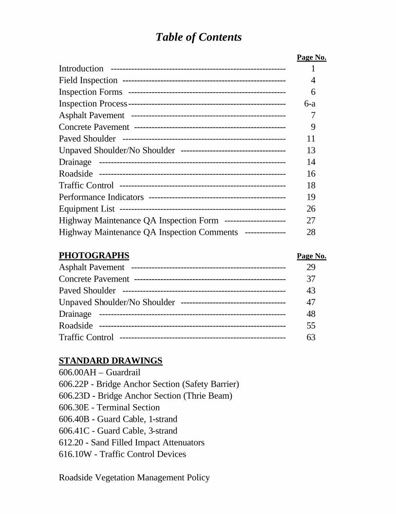
Table of Contents Page No. Introduction ------------------------------------------------------------ 1 Field Inspection -------------------------------------------------------- 4 Inspection Forms ------------------------------------------------------ 6 Inspection Process------------------------------------------------------ 6-a Asphalt Pavement ----------------------------------------------------- 7 Concrete Pavement ---------------------------------------------------- 9 Paved Shoulder -------------------------------------------------------- 11 Unpaved Shoulder/No Shoulder ------------------------------------ 13 Drainage ---------------------------------------------------------------- 14 Roadside ---------------------------------------------------------------- 16 Traffic Control --------------------------------------------------------- 18 Performance Indicators ----------------------------------------------- 19 Equipment List --------------------------------------------------------- 26 Highway Maintenance QA Inspection Form --------------------- 27 Highway Maintenance QA Inspection Comments -------------- 28 PHOTOGRAPHS Page No. Asphalt Pavement ----------------------------------------------------- 29 Concrete Pavement ---------------------------------------------------- 37 Paved Shoulder -------------------------------------------------------- 43 Unpaved Shoulder/No Shoulder ------------------------------------ 47 Drainage ---------------------------------------------------------------- 48 Roadside ---------------------------------------------------------------- 55 Traffic Control --------------------------------------------------------- 63 STANDARD DRAWINGS 606.00AH – Guardrail 606.22P - Bridge Anchor Section (Safety Barrier) 606.23D - Bridge Anchor Section (Thrie Beam) 606.30E - Terminal Section 606.40B - Guard Cable, 1-strand 606.41C - Guard Cable, 3-strand 612.20 - Sand Filled Impact Attenuators 616.10W - Traffic Control Devices Roadside Vegetation Management Policy

1
Introduction
The Missouri Department of Transportation (MoDOT) is responsible for constructing and operating the highways of the state system. Maintenance personnel within MoDOT have the responsibility of maintaining the highways to provide a safe, comfortable, and pleasant highway system, and to protect the state's capital investment. Our task is to develop a method to measure the overall quality of the highway system in an objective manner.
MoDOT's philosophy is centered on public expectations. Through public input, the public’s perception of the existing system, the degree of satisfaction expected, and the relative importance of various roadway features can be determined. The public’s perception of the existing system is used to develop performance indicators for various roadway features, which are then used to measure the quality of the service being provided. These performance indicators are objective measures and represent the minimum condition that can be allowed to exist before a specific feature is considered not to meet the desired expectations. Features being inspected are rated as either passing or failing the corresponding performance indicator. The ratings based on these performance indicators are then compared to public expectations.
Performance indicators rarely change. However, with this process, performance indicators are periodically adjusted to reflect changes in customer expectations. A performance indicator identifies the extent, dimension, capacity, or amount of certain characteristics present in a particular process. The key performance indicator associated with this process is the comparison between public expectations and level of service (LOS) provided.
The process developed by this team is based on the recommendations of the National Cooperative Highway Research Program (NCHRP) Report 422, Maintenance QA Program Implementation Manual. This manual was the result of the NCHRP Project 14-12, Highway Maintenance Quality Assurance, which was conducted for the purpose of researching current quality management concepts, evaluating existing maintenance quality programs, and developing a state-of-the-art maintenance quality assurance (QA) program.
Other states and agencies that have initiated a QA program and were mentioned in the NCHRP Report 422 were Florida, Maryland, Oregon (Region 4), Virginia, and British Columbia (Ministry of Transportation and Highways). The Washington State DOT instituted a comprehensive maintenance QA program known as the Maintenance Accountability Process (MAP). This program contains many of the features of the NCHRP Project 14-12 QA program.
Previously, District 7 started the development of a maintenance QA program following the guidelines of NCHRP Report 422. Employees in non-operations functional units were surveyed to get a base line for the weighting factors of the various features and elements. A short public opinion poll was also developed and distributed at various meetings with the general public within the district to gain public opinion on the condition of the existing system and the public’s expectations. Two series of inspections have been performed in District 7 to test and improve the process.

2
By using this process, MoDOT will have a uniform method for rating the LOS provided by maintenance activities statewide. Maintenance activities are identified and grouped into similar categories. The categories are Pavement, Shoulders, Drainage, Roadsides, and Traffic Control. Items not evaluated include: bridges (an existing rating system is in place), snow and ice removal (due to the frequency and variance of occurrence), traffic signals (safety issue and problems are quickly corrected), striping reflectivity (another team is establishing a management process), and aggregate routes (very few miles exist within the state system).
Characteristics to be measured within each category were identified. Performance indicators for each characteristic were then developed for the National Highway System (NHS), Arterials not on NHS, and Collector routes. It should be noted that not all characteristics in all segments to be inspected would pass these performance indicators. The desired LOS recommended by NCHRP Report 422 is “80.” This is a number that is publicly accepted and yet leaves room for the LOS to exceed expectations. Therefore, the performance indicators are developed such that some characteristics must fail.
The categories and the characteristics have differing importance levels to the motoring public; therefore, weighting factors must be assigned to them to rank them on their importance. These weighting factors are determined from public input and are used in the calculation of a LOS. Our team has obtained this public input from non-operations personnel in a number of districts. The questionnaire, which is filled out in conjunction with viewing of a power point presentation, provides visual examples of each type of distress.
The size of our system and impracticality of evaluating each mile of roadway necessitates the selection of a statistically valid sample of one-tenth mile segments for each functional roadway class for field inspection. Roadway features within the sample segments are then field inspected using the performance indicators as a basis to determine a LOS expressed as a number between 1 and 100. Individual segment ratings are then averaged to determine LOS ratings. Approximately 1,500 segment inspections stratified by functional class will provide a valid sample for the entire system’s LOS, and potentially valid information as to each district’s LOS.
Ultimately, the number of inspections should be increased to provide the LOS at the Area Engineer level. In theory, this information could be provided through a sophisticated stratification process coupled with a moderate increase in sample size. Results in District 7 indicate that we potentially may need a significant increase in sample size to provide data that is relevant to the Area Engineer level.
Florida has been using this process since 1992. Their system contains approximately 16,000 centerline miles and is classified into urban and rural interstates and primaries. The state is divided into 30 maintenance units. They sample 30 random locations for each classification (urban interstate, rural interstate, urban primary, and rural primary) within each maintenance unit three times per year. Their results for each classification are then averaged to eliminate seasonal variation.
A variety of resources will be required to inspect the roadway segments. The number of personnel committed to do the inspections directly impacts the time needed for completion of the inspections. We estimate that a minimum of one, two-person team per district will be

3
required to perform district inspections. Ultimately, timing of the inspections should link to our budget process.
Each team of raters will need a vehicle equipped with a distance-measuring device, safety warning lights, etc. Eventually, the rating system will be computerized and a laptop computer or handheld electronic communication device will be required.
Resource commitments will be required of Transportation Management Systems (TMS). They will select random segments to be inspected, then process and track the data collected. TMS will also need to develop the computer version of the rating system.
The proposed process can be utilized in several ways. It can assist managers in determining needs, setting priorities, allocating resources, and developing a zero based budget. In order to obtain uniformity throughout the state, it may be necessary to shift resources to obtain the minimum LOS expected by the traveling public. This QA process can also be used as a tool to help districts or work units comply with the MoDOT business plan.
Before this process can be utilized to its full potential, a roadway features inventory along with valid cost data for maintenance activities must be available. Without this data, the process cannot be used as a budget tool.
We are testing the viability of the process by performing inspections with a statistical sample which will provide valid data for statewide condition ratings for the Interstate System (IS), NHS minus the IS, Arterials not on the NHS, and Collectors. This initial inspection will require approximately 150 segment sites per district. Districts will have to provide staff for these inspections, which will have to be completed in six weeks. Due to time and funding restrictions, department personnel from non-operational units will continue to be utilized to provide the “public input.” Data from this test will reconcile our concerns as to the number of inspections required to provide information that is relevant to our Area Engineer regions.

4
Field Inspection A two-person team will perform district inspections. Each team will need a certain amount of equipment to perform the required field measurements. A list of the recommended equipment has been included in the Inspectors Rating Manual. A list of segments to be inspected will be provided to each inspection team. The segments to be inspected will be identified by beginning and ending log point. The inspection team will first locate the segment to be inspected. After the segment has been located, each team member will walk the segment noting and recording any obvious deficiencies. It may be necessary to make manual measurements to determine the not so obvious deficiencies. After both team members have completed their inspection of the segment, the team members will compare results. Discrepancies will be resolved at this time. After both team members agree upon the inspection results, the final inspection form will be completed. There will be occasions when the inspectors will have to make a judgment call. The rule of thumb in these instances is "If it is too close to call, it fails". The reasoning behind this theory is that the element in question will, most likely, not get better on its own. The amount of aggregate surfaced routes statewide is very small. Therefore, performance indicators for aggregate surfaced routes have not been developed. Consequently, aggregate surfaced routes will not be rated. Bridges are not to be inspected as part of this rating system. In the event that a segment listed to be inspected falls in part or in whole upon a bridge deck, the inspectors shall inspect the one-tenth mile segment nearest to the segment originally selected. The beginning and ending log points of the segment actually inspected shall be noted on the inspection forms. In the event that a segment listed to be inspected should fall in an area containing both asphalt and concrete pavement, the inspectors shall inspect the one-tenth mile segment that contains only one type of surface (asphalt or concrete) nearest to the segment originally selected. The beginning and ending log points of the segment actually inspected shall be noted on the inspection forms. Inspections shall not be performed within the limits of active work zones. Maintenance work zones tend to be of a short duration. In the event that a segment listed to be inspected should fall within the limits of an active maintenance work zone, the inspectors can either return at a later date when the work zone no longer exists and inspect the segment originally selected or they may select the 0.1 mile segment which is outside the limits of the work zone and nearest to the originally selected segment for inspection. Construction work zones tend to be of a longer duration. In the event that a segment listed to be inspected should fall within the limits of an active construction work zone, the inspectors shall select the one-tenth mile segment that is outside the limits of the work zone and nearest to the

5
originally selected segment for inspection. The log points of the segment actually inspected shall be recorded on the inspection form. For the purposes of this inspection, a shoulder is defined as any area beyond the normal driving lane (edge of pavement) having a width of twelve (12) inches or greater and a slope of 12:1 (12 horizontal, 1 vertical) or flatter.
6
Inspection Forms The Highway Maintenance Quality Assurance Inspection rating form is used to record the data obtained during the field inspection. Preprinted inspection forms will be provided. A blank sample form has been included in the Inspectors Rating Manual. The form has space to identify the segment being inspected as well as boxes that can be checked to signify whether or not the sampled element meets the performance indicators. Each preprinted form provides sufficient space to enter the inspection information of two segments. The inspector should start the completion of the form by entering the date and the inspectors' names. The inspectors should then proceed with the inspection of the selected segment. Three columns have been provided for the inspection results of each segment (Pass, Fail & N/A). If an element within a segment meets or exceeds the corresponding performance indicator, the inspector should place a check mark in the "Pass" column for that element. Likewise, if the chosen element does not meet the particular performance indicator, the inspector should place a check mark in the "Fail" column for that element. If a particular element does not "apply" to the selected segment, the inspector should place a check mark in the "N/A" column. The best way to explain whether or not an element applies to a particular segment is to determine if that element "exists" or if that element has the "potential" to exist within the segment. For instance, if there are no highway signs within the segment being inspected, the inspector would place a check mark in the "N/A" column. If highway signs exist that meet the performance indicators, the inspector would place a check mark in the "Pass" column. If highways signs exist and do not meet the performance indicators, the inspector would place a check mark in the "Fail" column. The same would hold true for box culverts, pipe culverts, drop inlets, etc. Likewise, potholes, cracking, patching, etc. have the potential to exist in pavement and shoulders and should be rated as "Pass" or "Fail" only. The Highway Maintenance Quality Assurance Comments form is used to identify elements within a segment that have not met the performance indicators. The inspectors shall enter the county, route (including special designations), the priority, the direction (if divided pavement), and the beginning and ending mile point designation. The inspectors shall then enter a brief comment describing the reason the element within the inspected segment did not meet the corresponding performance indicator. This information will be retained and referred to in case of dispute or if needed to determine programming needs. Pictures of elements that do not meet performance indicators shall also be taken and the number(s) of the picture(s) shall be recorded in the remarks column. A sample form has been included in the Inspectors Rating Manual.

7
Asphalt Pavement Asphalt pavements include all pavements other than concrete. Performance indicators have been developed to define the minimum conditions acceptable for the elements of potholes, cracking, raveling/stripping, edge raveling, bleeding/flushing, shoving, rutting, depressions/bumps, and patching. Inspections shall be performed in the following manner.
Potholes. Potholes create an undesirable appearance, deter a smooth ride, damage vehicle suspensions, and can cause a motorist to lose control of a vehicle. The area and depth of a pothole should be measured to determine if the pavement defect should be considered as a pothole for these inspection purposes. The depth of a pothole should be measured by placing a straightedge over the affected area. Measurement of the depth should be made to the deepest point. The area of the pothole should also be measured. Several methods could be used to estimate this quantity. The area of a round pothole could be estimated by measuring the diameter and then calculating the area of a circle. The area of the pothole could also be estimated by using a straightedge to approximate the pothole area as a rectangle or square and then measuring the sides of the rectangle or square. Potholes do not meet the desired pavement condition if both the area and the depth exceed the performance indicators. Cracking. Unsealed cracks and joints permit the intrusion of water that damages the pavement and sub grade. The measurement of cracking is not as difficult as it may seem. Any crack in a lane of traffic, exceeding the desired conditions, is considered to affect the entire width of that lane. The sum of the total lane length of undesired cracks can then be measured and compared to the total lane lengths within the segment being inspected to obtain the resultant percentage. Raveling/Stripping. Raveling or stripping is caused by deteriorated asphalt binder or the lack of asphalt binder permitting the loss of aggregate. Raveling or stripping is most easily identified by areas that have a rough texture. The sum of the areas of pavement showing signs of raveling or stripping can be measured and then compared to the total area of pavement within the segment being inspected to obtain the resultant percentage. Edge Breakup. The total driving surface of the pavement should be in sound condition. Edge breakup is unsightly and can cause damage to vehicles. The sum of the lengths of pavement edge breakup can be compared to the total length of pavement edge within the segment being inspected to obtain the resultant percentage. Bleeding/Flushing. Bleeding or flushing is caused by an excessive amount of asphalt binder on the pavement surface. Each individual area can be measured. The sum of the individual areas can then be compared to the total area of pavement within the segment being inspected to obtain the resultant percentage. Shoving. Shoving is the lateral movement of the asphalt surface. In the early stages, shoving can be detected in hot mix asphalt by the presence of rounded cracks in the direction of traffic in the pavement surface. In the latter stages, it may create bumps,

8
ruts, or potholes. Shoving in cold mixed asphalt surfaces generally appears as bumps, depressions, ruts, ridges, etc. The sum of the affected areas can be compared to the total area of pavement within the segment being inspected to obtain the resultant percentage. Rutting. Rutting creates an uneven driving surface and tends to pond water during rainstorms. The depth of a rut can be measured by placing a straightedge over the rut or stretching a string line across the entire width of the pavement and then measuring the depth of the ruts using the rut gauge. Depressions/Bumps. Depressions and bumps in the pavement surface deter from a smooth driving surface. The depth of a depression can be measured by placing a 4-foot straightedge over the affected area and measuring the depth. The height of a bump can be measured by placing the straightedge on the top of the bump and measuring the distance to the normal pavement surface. Patching. Rotomilled patches should be placed as uniform with the normal pavement surface as possible. An excessive number of patches subtracts from the appearance of the pavement. The distance the patch is higher or lower than the surrounding pavement surface can be measured by placing a straightedge over the patch and measuring the distance from the straightedge to the patch, if the patch is lower than the surrounding pavement, or the distance from the patch to the normal pavement surface, if the patch is higher than the surrounding pavement. Surface patches should be uniformly feathered out and rolled to obtain a minimum height differential between the patch and the adjacent pavement surface.

9
Concrete Pavement Concrete pavement will consist of only portland cement concrete pavement. Performance indicators have been developed to define the minimum conditions acceptable for the elements of potholes, spalls/popouts, cracking, joints, depressions/bumps, pumping, faulting, and patching. Inspections shall be performed in the following manner.
Potholes. Potholes create an undesirable appearance, deter a smooth ride, damage vehicle suspensions, and can cause a motorist to loose control of a vehicle. The area and depth of a pothole should be measured to determine if the pavement defect should be considered as a pothole for these inspection purposes. The depth of a pothole should be measured by placing a straightedge over the affected area. Measurement of the depth should be made to the deepest point. The area of the pothole should also be measured. Several methods could be used to estimate this quantity. The area of a round pothole could be estimated by measuring the diameter and then calculating the area of a circle. The area of the pothole could also be estimated by using a straightedge to approximate the pothole area as a rectangle or square and then measuring the sides of the rectangle or square. Potholes do not meet the desired pavement condition if both the area and the depth exceed the performance indicators. Spalls/Popouts. Popouts are areas where pieces of large individual aggregate have popped out of the surface of the concrete pavement. Spalls are areas where a larger piece of the surface of the concrete pavement is missing. The area of pavement containing spalls/popouts can be measured and compared to the total area of pavement within the segment being inspected to obtain the resultant percentage of surface area affected. The length of spalled joints or cracks can be measured and compared to the total length of joints or cracks within the segment being inspected to obtain the resultant percentage. Cracking. Unsealed cracks in the concrete pavement allow water to enter the sub grade. A pavement panel (the area within the construction joints) does not meet standards if it contains a crack of such size that it should be sealed. The number of panels containing such cracks can be counted and compared to the total number of panels within the segment being inspected to obtain the resultant percentage. Joints. Unsealed joints in the concrete pavement allow water to enter the sub grade. The length of unsealed joints can be measured and compared to the total length of joints within the segment being inspected to obtain the resultant percentage. Depressions/Bumps. Depressions and bumps in the pavement surface deter from a smooth driving surface. The depth of a depression can be measured by placing a 4-foot straightedge over the affected area and measuring the depth. The height of a bump can be measured by placing the straightedge on the top of the bump and measuring the distance to the normal pavement surface. Pumping. Pumping is the vertical movement of a concrete pavement slab. Movement of a concrete pavement slab can be evidenced by watching the pavement under traffic or by the presence of muddy material on the pavement or shoulder

10
surface. The number of pavement slabs showing evidence of pumping can be counted and compared to the total number of slabs within the segment being inspected to obtain the resultant percentage. If the pumping is evidenced at a joint between two slabs, consider that both slabs adjacent to the joint are pumping. Faulting. Faulting occurs when the concrete pavement adjacent to a joint or crack develops a step or vertical offset in elevation. The amount of fault can be measured by placing a straightedge on the highest side of the joint or crack and measuring the distance to the adjacent concrete surface. The number of concrete pavement panels showing evidence of faulting can be counted and compared to the total number of panels within the segment being inspected to obtain the resultant percentage. Patching. Patches in the concrete pavement, whether asphalt or concrete, should be the same elevation as the adjacent concrete to provide a smooth riding surface. The smoothness of the patch can be measured by placing a straightedge over the patched area and measuring the distance to the adjacent concrete surface, in the case of a high patch, or to the patched area itself, in the case of a low patch.
11
Paved Shoulder Paved shoulders are shoulders that have a surface of asphalt, concrete, or oiled aggregate. Performance indicators have been developed to define the minimum conditions acceptable for the elements of pavement/shoulder joint, drainage, vegetation growth, potholes, cracking, distortion, drop-off/buildup, edge raveling, and faulting. Inspections shall be performed in the following manner.
Pavement/Shoulder Joint. The joint between the shoulder and the pavement should be sealed to prevent water from entering the sub grade. The length of pavement/shoulder joint not meeting the performance indicators can be measured and compared to the total length of joint within the segment being inspected to obtain the resultant percentage. Drainage. The shoulders should be properly sloped to permit water from ponding on the shoulder or the driving surface. The length of shoulder that does not permit proper drainage can be measured and compared to the total length of shoulder within the segment being inspected to obtain the resultant percentage. Vegetation Growth. Grass, weeds, etc. growing from the cracks in the paved shoulders create an unpleasant sight. Measurement of the length of shoulder with vegetation growing can be measured and compared to the total length of shoulder within the segment being inspected to obtain the resultant percentage. Potholes. Potholes create an undesirable appearance, deter a smooth ride, damage vehicle suspensions, and can cause a motorist to loose control of a vehicle. The area and depth of a pothole should be measured to determine if the pavement defect should be considered as a pothole for these inspection purposes. The depth of a pothole should be measured by placing a straightedge over the affected area. Measurement of the depth should be made to the deepest point. The area of the pothole should also be measured. Several methods could be used to estimate this quantity. The area of a round pothole could be estimated by measuring the diameter and then calculating the area of a circle. The area of the pothole could also be estimated by using a straightedge to approximate the pothole area as a rectangle or square and then measuring the sides of the rectangle or square. Potholes do not meet the desired pavement condition if both the area and the depth exceed the performance indicators. Cracking. Unsealed cracks in the paved shoulders allow water to enter the sub grade. A length of paved shoulder does not meet standards if it contains a crack of such size that it should be sealed. The length of paved shoulder containing such cracks can be measured and compared to the total length of shoulder within the segment being inspected to obtain the resultant percentage. Distortion. Distortion is a vertical deviation in the longitudinal profile of the shoulder. This can occur as occasional high or low areas or may occur as short wavy sections. It is possible that short sections could be measured with a straightedge but it will be necessary to use a string line to aid in determining the vertical distortion in most areas.

12
Drop-off/Buildup. Pavement edge differential is a serious concern. Pavement edge differential greater than 2" places the department in a very serious liability situation. The length of pavement edge not meeting performance indicators can be measured and compared to the total length of pavement edge within the segment being inspected to determine the resultant percentage. Edge Raveling/Breakup. The total surface of the paved shoulder should be in sound condition. Edge breakup is unsightly and can lead to further shoulder breakup. The sum of the lengths of paved shoulder edge breakup can be compared to the total length of paved shoulder edge within the segment being inspected to obtain the resultant percentage. Faulting. Faulting occurs when the concrete pavement adjacent to a joint or crack develops a step or difference in elevation. The amount of fault can be measured by placing a straightedge on the highest side of the joint or crack and measuring the distance to the adjacent concrete surface. The number of concrete pavement panels showing evidence of faulting can be counted and compared to the total number of panels within the segment being inspected to obtain the resultant percentage.
13
Unpaved Shoulder/No Shoulder Unpaved shoulders are shoulders that have a surface of aggregate or soil. Performance indicators have been developed to define the minimum conditions acceptable for the elements of drainage, distortion, drop-off/buildup, and vegetation growth. Inspections shall be performed in the following manner. NOTE: For the purposes of this inspection, a shoulder is defined as any area beyond the normal driving lane (edge of pavement) having a width of twelve (12) inches or greater and a slope of 12:1 (12 horizontal, 1 vertical) or flatter.
Drainage. The shoulders should be properly sloped to permit water from ponding on the shoulder or the driving surface. The shoulders should also be compacted and sloped sufficiently to prevent erosion. The length of shoulder that does not meet the performance indicators can be measured and compared to the total length of shoulder within the segment being inspected to obtain the resultant percentage. The length and width of ruts can also be measured. Distortion. Distortion is a vertical deviation in the longitudinal profile of the shoulder. This can occur as occasional high or low areas or may occur as short wavy sections. It is possible that short sections could be measured with a straightedge but it will be necessary to use a string line to aid in determining the vertical distortion in most areas Drop-off/Buildup. Pavement edge differential is a serious concern. Pavement edge differential greater than 2" places the department in a very serious liability situation. The length of pavement edge not meeting the performance indicators can be measured and compared to the total length of pavement edge within the segment being inspected to determine the resultant percentage. Vegetation Growth. Vegetation growth accelerates the deterioration of aggregate shoulders and detracts from the overall appearance. Aggregate shoulders shall be free of all vegetative growth. Unpaved shoulders with no aggregate surface shall be covered with a dense stand of desirable vegetation. Maintenance shall be in accordance with the Roadside Vegetation Management Manual.

14
Drainage Proper drainage is necessary to prevent flooding of the roadway surface during periods of heavy rainfall. Performance indicators have been developed to define the minimum conditions acceptable for the elements of roadside ditch, outfall ditch, median ditch, paved ditch, box culverts, pipe culverts, storm drains, catch basins/drop inlets, and curb/gutter. Inspections shall be performed in the following manner.
Roadside Ditch. The roadside ditch is the ditch that parallels the roadway. Ditches should be clear of debris that will obstruct drainage. The cross-sectional area of any obstruction in a roadside ditch can be measured and compared to the total cross-sectional area of the ditch to obtain the resultant percentage. Outfall Ditch. An outfall ditch is a ditch draining from the right of way. The cross-sectional area of any obstruction in an outfall ditch can be measured and compared to the total cross-sectional area of the ditch to obtain the resultant percentage. Median Ditch. A median ditch is the ditch separating two lanes of pavement. The cross-sectional area of any obstruction in a median ditch can be measured and compared to the total cross-sectional area of the ditch to obtain the resultant percentage. Paved Ditch. A paved ditch is any roadside, outfall, or median ditch that has been lined with a durable material such as asphalt, concrete, or grouted aggregate. A paved ditch should be rated separate from a normal roadside, outfall, or median ditch. Areas that show signs of structural distress can be measured and compared to the total area of paved ditch within the segment being inspected to obtain the resultant percentage. The cross-sectional area of any obstruction in a paved ditch can be measured and compared to the total cross-sectional area of the ditch to obtain the resultant percentage. Box Culverts. The cross-sectional area of any obstruction can be measured and compared to the total cross-sectional area of the structure to obtain the resultant percentage. Pipe Culverts. The cross-sectional area of any obstruction can be measured and compared to the total cross-sectional area of the structure to obtain the resultant percentage. Any evidence of roadway settlement can be determined by viewing the roadway over the pipe culvert from the in slope or with the use of a string line. Storm Drains. The cross-sectional area of any obstruction can be measured and compared to the total cross-sectional area of the structure to obtain the resultant percentage. Catch Basins/Drop Inlets. The cross-sectional area of any obstruction can be measured and compared to the total cross-sectional area of the structure to obtain the resultant percentage.

15
Curb/Gutter. The cross-sectional area of any obstruction can be measured and compared to the total cross-sectional area of the structure to obtain the resultant percentage for obstructions. Areas showing signs of structural distress can be measured and compared to the total area within the segment being inspected to obtain the resultant percentage of structural distress. The length of joints in which the adjacent sides are not even or the joint is not properly filled with joint filler can be measured and compared to the total length of joints within the segment being inspected to determine the resultant percentage for the joint criteria.

16
Roadside The right of way should present a neat and pleasant appearance. This leads to a more pleasant driving experience for the motorist. Performance indicators have been developed to define the minimum conditions acceptable for the elements of mowing, litter/debris, brush & tree control, graffiti, fence, sidewalks, slopes, and turf/sod. Inspections shall be performed in the following manner.
Mowing. Proper mowing of the right of way creates a more pleasing appearance to the motorist. Mowing should be performed in accordance with the latest mowing standards. The visibility can be checked while seated in the vehicle. Visibility in all directions should be checked. The height of vegetation can be checked with the use of a folding rule. Litter/Debris. The absence of litter or debris on the roadway or within the right of way creates a more pleasing appearance to the motorist and leads to a more pleasant and safe driving experience. Tires and tire parts within the limits of the driving surface also create a hazard to motorists. Litter can be measured by placing the litter in a trash bag of the specified size. Tire particles can be measured to determine the area. Brush & Tree Control. The control of brush and trees not only affect the appearance of the right of way but may also affect the safety of an errant vehicle. Tree limbs overhanging the driving surface create a hazard for tall vehicles. Brush and tree limbs overhanging a sidewalk are a nuisance and create somewhat of a hazard to pedestrians. Tree limbs and brush should not obstruct the visibility of highway signing or at sight corners. Vegetation determined to be noxious should not be present. Graffiti. Graffiti distracts from the appearance of the right of way and often times offend motorists and pedestrians. Fence. State owned and maintained fence should not be damaged, should function as intended, and should present a neat appearance. The length of fence in disrepair or malfunction can be measure and compared to the total length of fence within the segment being inspected to obtain the resultant percentage. Sidewalks. Sidewalks are for pedestrian use and should not present any hazards. Sidewalks should not be cracked, spalled, or faulted and should not have areas that have heaved or settled. The area of sidewalk showing signs of structural distress can be measured and compared to the total area of sidewalk within the segment being inspected to obtain the resultant percentage. Slopes. Slopes should present a neat and uniform appearance. Slide and washouts should be repaired. Areas of slides and washouts can be measured and compared to the total area of slope within the segment being inspected to obtain the resultant percentage.

17
Turf/Sod. Proper ground coverage is necessary to prevent erosion. Areas not having sufficient ground coverage should be seeded. Areas of improper ground coverage can be measured and compared to the total area where ground cover is applicable within the limits of the segment being inspected to obtain the resultant percentage.

18
Traffic Control Traffic control is very important. Traffic control items assist the motorist in numerous ways varying from helping with directions, determining traffic movement, delineating roadways, providing safety, controlling errant vehicles, etc. Performance indicators have been developed to define the minimum conditions acceptable for the elements of signs, object markers, delineators, barrier wall, guardrail, guard cable, and impact attenuators. Inspections shall be performed in the following manner. NOTE: Traffic signals are not a part of this inspection.
Signs. MUTCD, the Traffic Signing Manual, the latest revision of Std. Dwg. 616.10, and the latest edition of the Quality Standards for Work Zone Traffic Control Devices may be used as guidelines to determine the proper reflectivity, mounting height, and permissible damage. Post alignment can be determined by using a carpenters level and measuring the distance out of plumb and dividing by the length of the level to determine the distance per foot that the post is out of plumb. Object Markers. MUTCD, the Traffic Signing Manual, the latest revision of Std. Dwg. 616.10, and the latest edition of the Quality Standards for Work Zone Traffic Control Devices may be used as guidelines to determine the proper reflectivity, mounting height, and permissible damage. Delineators. MUTCD, the Traffic Signing Manual, the latest revision of Std. Dwg. 616.10, and the latest edition of the Quality Standards for Work Zone Traffic Control Devices may be used as guidelines to determine the proper reflectivity, mounting height, and permissible damage. Barrier Wall. The alignment of a barrier wall can be checked with a string line. Guardrail. MUTCD and the latest revision of Std. Dwgs. 606.00, 606.22, 606.23,and 606.30 may be used as guidelines to determine the proper alignment, missing parts, and proper mounting height. Guard Cable. MUTCD, the latest revision of Std. Dwg. 606.40, and Std. Dwg. 606.41 may be used as guidelines to determine the proper alignment, tension, and mounting height. Impact Attenuators. MUTCD and the latest revision of Std. Dwg. 612.20 may be used as guidelines to determine the proper installation. Pavement Marking. Pavement marking shall be maintained in accordance with the Traffic Striping Manual. Lighting. All facilities shall exhibit no signs of vehicle damage and shall be operational.

19
Missouri Department of Transportation
Performance Indicators
Asphalt Pavement
Characteristic
Performance Indicator (0.1 Mile Segment)
Potholes A pothole is defined as any defect greater than or equal to 1.0 in. in depth and 72 sq. in. in area. Allowable number: National Highway System = 0, Arterial and Collector System = 1.
Cracking 100% of the National Highway System, 100% of the Arterial System, and 90% of the Collector System pavements shall be free of unsealed cracks greater than or equal to 0.25 in. No areas of alligator / map cracking greater than 25 sq. ft. on the National Highway System and the Arterial System or 75 sq. ft. on the Collector System shall exist.
Raveling/Stripping 100% of the pavement surface shall be free of evidence of dislodged aggregate particles.
Edge Breakup 100% of the total roadway edge, within the outermost 4 in., shall be free of raveling or broken pavement.
Bleeding/Flushing The sum of the affected areas shall not be greater than 25 sq. ft. on the National Highway System and the Arterial System, and not greater than 75 sq. ft. on the Collector System.
Shoving No area on National Highway System routes shall exhibit the appearance of shoving. 90% of the pavement surface on remaining routes shall not exhibit the appearance of shoving.
Rutting 90% of the pavement surface shall be free of ruts greater than 0.25 in. in depth and no rut greater than 0.5 in. in depth and 10 ft. in length shall exist.
Depressions/Bumps No vertical deviation in the pavement profile shall be greater than 0.125 in. in 4 ft. This does not apply to depressions less than 1 in. in width in cracks.
Patching Rotomilled patches greater than 0.25 in. higher or lower than the adjacent pavement surface do not meet standards. Surface patches greater than 5/8” higher than the adjacent pavement surface do not meet standards. Allowable number: National Highway System = 0, Arterial System = 1, Collector System = 2. For aesthetic reasons, no more than 5 patches per lane shall exist on any system.

20
Missouri Department of Transportation
Performance Indicators
Concrete Pavement
Characteristic
Performance Indicator (0.1 Mile Segment)
Potholes A pothole is defined as any defect greater than or equal to 1.0 in. in depth and 72 sq. in. in area. Allowable number: National Highway System and Arterial System = 0, Collector System = 1.
Spalls/Popouts 95% of the roadway surface shall be free of spalls/popouts greater than 0.5 in. in depth and 2 in. in diameter. Less than 10% of cracks and joints have spalled to a surface width of 2 in. and a depth of 0.5 in.
Cracking 100% of the National Highway System, 100% of the Arterial System, and 90% of the Collector System pavements shall be free of unsealed cracks greater than or equal to 0.25 in. in width. No areas of alligator / map cracking greater than 25 sq. ft. on the National Highway System and the Arterial System or 75 sq. ft. on the Collector System shall exist.
Joints 90% of the length of all joints shall be sealed and functioning as intended. No evidence of D-cracking shall exist.
Depressions/Bumps No vertical deviation in the pavement profile shall be greater than 0.125 in. in 4 ft. This does not apply to depressions in cracks less than 1 in. in width or faults.
Pumping 100% of the pavement slabs shall show no evidence of pumping. Faulting 100% of the joints and cracks shall not exhibit a difference in the elevation
of the adjacent sections of pavement greater than or equal to 0.25 in. Patching Concrete or asphalt patches greater than 0.25 in. higher or lower than the
adjacent pavement surface do not meet standards. Allowable number: National Highway System = 0, Arterial System = 1, Collector System = 2. For aesthetic reasons, no more than 5 patches per lane shall exist on any system.

21
Missouri Department of Transportation
Performance Indicators
Paved Shoulder
Characteristic
Performance Indicator (0.1 Mile Segment)
Pavement/Shoulder Joint 90% of the length of the pavement/shoulder joints greater than or equal to 0.25 in. in width shall be sealed.
Drainage 100% of the shoulder shall be free of any evidence of severe flooding, ponding, or pumping and there is no occurrence of a level or negative slope.
Vegetation Growth 100% of the shoulder shall be free of vegetation growth. Potholes A pothole is defined as any defect greater than or equal to 1.5 in. in
depth and 72 sq. in. in area. Allowable number: National Highway System & Arterial System = 0, Collector System = 1.
Cracking Paved shoulders on 100% of the National Highway System, 95% of the Arterial System, and 90% of the Collector System shall be free of unsealed cracks greater than or equal to 0.25 in. in width.
Distortion No longitudinal vertical deviation of the shoulder profile shall be greater than 0.5 in. in 10 ft.
Drop-off/Buildup 90% of the length of the joint between the outside edge of the traffic lane and the inside edge of the shoulder shall not exhibit an elevation difference greater than 0.5 in.
Edge Raveling/Breakup 100% of the total shoulder edge, within the outermost 4 in., shall be free of raveling or broken pavement.
Faulting 95% of the joints and cracks shall not exhibit a difference in the elevation of the adjacent sections of pavement greater than or equal to 0.25 in.

22
Missouri Department of Transportation
Performance Indicators
Unpaved Shoulder/No Shoulder
Characteristic
Performance Indicator (0.1 Mile Segment)
Drainage 100% of the National Highway System, 90% of the Arterial System, and 85% of the Collector System shoulder length shall be free of any occurrences of standing water (ponding) or erosion and shall also be free of ruts greater than 3 in. in width, 1 in. in depth, and 25 ft. in length.
Distortion No areas shall exist where the longitudinal profile differential between the low point and high point is greater than 1 in. in 25 ft. for aggregate shoulders and 1 in. in 10 ft. for sodded shoulders.
Drop-off/Buildup If a shoulder is present, 90% of the length of the pavement edge drop-off shall not exceed 1 in., and no vertical pavement edge drop-off greater than 1.5 in. shall exist. Any pavement edge drop-off greater than 1.5 in. and less than or equal to 3.5 in. shall be on a 1:1 (horizontal:vertical) slope or flatter. Any pavement edge drop-off greater than 3.5 in. shall be on a 3:1 (horizontal:vertical) slope or flatter. 90% of the length of the pavement edge buildup shall not exceed 0.5 in.
Vegetation Growth 100% of aggregate shoulders shall be free of vegetation growth. Sodded shoulders shall conform to the current mowing policy.

23
Missouri Department of Transportation
Performance Indicators
Drainage
Characteristic
Performance Indicator (0.1 Mile Segment)
Roadside Ditch 100% of the cross-sectional area shall be unobstructed and functioning as intended. No erosion or scour exceeding 12 in. in depth and 10 ft. in length shall exist.
Outfall Ditch 100% of the cross-sectional area shall be unobstructed and functioning as intended. No erosion or scour exceeding 12 in. in depth and 10 ft. in length shall exist.
Median Ditch 100% of the cross-sectional area shall be unobstructed and functioning as intended. No erosion or scour exceeding 6 in. in depth and 10 ft. in length shall exist.
Paved Ditch 90% of paved area shall be structurally sound and 90% of cross-sectional area shall be unobstructed and functioning as intended. No portion shall exhibit signs of horizontal or vertical movement. No portion shall exhibit signs of undermining.
Box Culverts 90% of the cross-sectional area shall be unobstructed and functioning as intended.
Pipe Culverts 90% of the cross-sectional area shall be unobstructed and functioning as intended. No visible evidence of roadway settlement shall exist.
Storm Drains 90% of the cross-sectional area shall be unobstructed and functioning as intended.
Catch Basins/Drop Inlets 90% of the inlet opening and basin outlet opening shall be unobstructed, the unit shall be structurally sound, and the inlet grates and access covers (where applicable) shall be present and functioning as intended.
Curb/Gutter 100% of the gutter length shall be free of obstructions that would impede drainage flow. 90% of the curb and gutter area shall be free of structural distress. 90% of all joints shall be flush and filled with joint material. No evidence of ponding shall exist.

24
Missouri Department of Transportation
Performance Indicators
Roadside
Characteristic
Performance Indicator (0.1 Mile Segment)
Mowing Mowing shall be done in accordance with the latest mowing standards. Visibility shall not be impaired because of vegetation growth.
Litter/Debris Maximum of the equivalent of one, 5-gallon trash bag of readily visible litter or debris. No tire, wood, plastic or metal pieces in excess of 100 sq. in. on the roadway.
Brush & Tree Control 100% of the travelway shall be free of encroachment of tree limbs for a vertical distance of 18 ft. 100% of the sidewalk shall be free of encroachment of limbs for a vertical distance of 7 ft. 100% of the signs shall be visible for a distance of 200 ft. in urban areas and 300 ft. in rural areas. 100% of the right of way at sight corners shall be free of brush and trees that have a height in excess of 30 in. above the edge of the pavement. 100% of the right of way shall be free of hazardous, leaning, or dead trees capable of falling onto the roadway.
Graffiti 100% of the area shall be free of graffiti. Fence 100% of state maintained fence shall be in good repair and
functioning as intended. Sidewalks/Bicycle Trails 75% of the sidewalk/bicycle trail shall be free of structural dis tresses
(faulting, cracking, spalling, heaving, and settlement). Slopes 100% of the slope area shall not exhibit a slide or washout greater
than 1 ft. in depth and 1 ft. in width. Turf/Sod 95% of the unpaved area shall have proper vegetative ground cover.
This does not include the rock surface in rock cuts or fill areas constructed predominately of rock. 100% of the right of way shall be clear of noxious weed growth; i.e. Johnson Grass, Thistle, etc.

25
Missouri Department of Transportation
Performance Indicators
Traffic Control
Characteristic
Performance Indicator (0.1 Mile Segment)
Signs Signs shall be reflective, undamaged, free of graffiti, securely mounted at the proper height, and correct for the intended purpose. Post alignment shall not exceed 0.25 in. per ft. from vertical.
Object Markers 100% of the markers shall be reflective, mounted at the proper height (48 in. minimum to bottom of marker), undamaged, and correct for the intended purpose. Post alignment shall not exceed 0.25 in. per ft. from vertical.
Delineators 100% of delineators shall be reflective, mounted at the proper height, undamaged, and correct for the intended purpose.
Barrier Wall 100% of all concrete barrier shall be free of structural distress. No deviation in the horizontal alignment shall exceed 1 in. in 20 ft.
Guardrail 100% of each continuous section shall have posts properly aligned, be free of missing parts, mounted at the proper height (21 in., +/- 3 in., to center of rail), and functioning as intended. No deviation in horizontal alignment greater than 3 in. shall exist.
Guard Cable 100% of each continuous section shall be properly aligned, properly tensioned, mounted at the proper height (21 in. at post), and functioning as intended. No deviation in the horizontal alignment greater than 1 in. in medians on divided highways or 3 in. at other locations shall exist.
Impact Attenuators 100% shall be properly installed, show no major damage, and functioning as intended.
Pavement Marking The location of the original pavement striping shall be within 4 in. of the proper location. The location of subsequent pavement striping shall be within 2 in. of the previous stripe on the width and within 3 in. of the previous stripe on the length. No more than 10% of any individual stripe may be obliterated.
Highway Lighting 100% of the lighting facilities shall be operational. Light poles shall exhibit no signs of vehicular damage.

26
Equipment List
Ø List of segments to be inspected
Ø State map
Ø County maps
Ø Log point information
Ø Survey odometer
Ø Paint stick
Ø Safety vest
Ø Flashing amber light
Ø Leather gloves
Ø Clipboard
Ø Condition standards
Ø Rating forms
Ø Pencil and eraser
Ø Pocket ruler (6-in.)
Ø Pocket calculator
Ø Measuring tape (25 ft.)
Ø Cloth tape (100 ft.) [measuring wheel optional]
Ø Straight edge (4-ft. minimum)
Ø Carpenter’s level (4 ft.)
Ø String line (100 ft.+)
Ø Hammer (20-oz.)
Ø Nails (1-in. concrete)
Ø Nails (12d)
Ø Wood blocks (2, 1-in.)
Ø Heavy duty pry bar
Ø Camera and film (digital preferred)
Ø Range pole or survey rod (capable to 18 ft.)
Ø Screwdriver with ¼-in. shank

Highway MaintenanceQuality Assurance Inspection
DATE CLASSIFICATION (IS, NHS, ART., COL.)
COUNTY DISTRICT ROUTE
DIRECTION NUMBER OF LANES BEGIN/END MILEPOINT / / / /
Inspector MEETS DESIRED CONDITIONSCategory Maintenance Element PASS FAIL N/A PASS FAIL N/A PASS FAIL N/A PASS FAIL N/APAVEMENTFlexible Potholes
CrackingRaveling/StrippingEdge Raveling/BreakupBleeding/FlushingShovingRuttingDepressions/BumpsPatching
Rigid PotholesSpalls/PopoutsCrackingJointsDepressions/BumpsPumpingFaultingPatching
SHOULDERSPaved Pavement/Shoulder Joint
DrainageVegetation GrowthPotholesCrackingDistortionDrop-off/BuildupEdge RavelingFaulting
Unpaved DrainageDistortionDrop-off/BuildupVegetation Growth
DRAINAGERoadside DitchOutfall DitchMedian DitchPaved DitchBox CulvertsPipe CulvertsStorm DrainsCatch Basins/Drop InletsCurb/Gutter
ROADSIDEMowingLitter/DebrisBrush/Tree ControlGraffitiFenceSidewalksSlopesTurf/Sod
TRAFFIC CONTROLSignsObject MarkersDelineatorsBarrier WallGuardrailGuard CableImpact AttenuatorsPavement MarkingHighway Lighting
27

Highway MaintenanceQuality Assurance Inspection Comments
Begin EndCounty Route Prior. Dir. Mile Mile Comments
8/28/2003 1

Asphalt Pavement
29
A pothole is a fairly round hole in the pavement surface. Potholes are abusive to tires and suspensions of vehicles. Motorists often swerve to
avoid hitting a pothole.
The depth should be measured to the deepest point of the pothole using a straight edge to determine approximately where the driving surface
should have been.

Asphalt Pavement
30
Cracks in asphalt pavement allow for the intrusion of water, which leads to pavement failure.
Cracks greater than or equal to 0.25 inches in width should be sealed. Narrower cracks do not allow for the sealer to penetrate into the crack.

Asphalt Pavement
31
A Phillips screwdriver, or similar instrument, with a 1/4 in. shank is a good tool to measure the width of cracks.
Edge raveling often leads to edge drop off. Pavement within the outermost 4 inches shall not exhibit signs of severe cracking
or edge raveling.
Asphalt Pavement
32
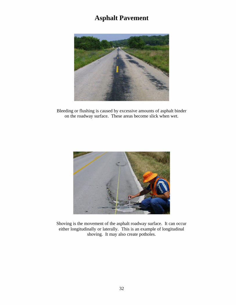
Bleeding or flushing is caused by excessive amounts of asphalt binder on the roadway surface. These areas become slick when wet.
Shoving is the movement of the asphalt roadway surface. It can occur either longitudinally or laterally. This is an example of longitudinal
shoving. It may also create potholes.

Asphalt Pavement
33
This is an example of lateral shoving. It may also create ruts in the pavement surface.
Rutting creates an uneven driving surface and traps or ponds water during rainstorms. This can cause a vehicle to hydroplane.

Asphalt Pavement
34
Rutting at an intersection approach
Rutting should be measured with a straight edge and folding rule.
Asphalt Pavement
35
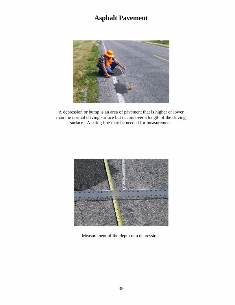
A depression or bump is an area of pavement that is higher or lower than the normal driving surface but occurs over a length of the driving
surface. A string line may be needed for measurement.
Measurement of the depth of a depression.

Asphalt Pavement
36
Patches should be flush with the surrounding pavement surface. Measurement may be made with a straight edge and folding rule.

Concrete Pavement
37
Some spalls/popouts should be measured to determine if they qualify as a pothole.
Procedure to measure the depth of a possible pothole.

Concrete Pavement
38
Spalls or popouts are areas where the surface of the concrete pavement has broken loose and popped out often exposing the reinforcing steel.
This is an example of a spall/popout, a possible pothole, an unsealed joint, cracking, and a patch. All within a few feet of pavement.

Concrete Pavement
39
Another example of an unsealed crack, a possible pothole, and a patch.
Another example of a spall/popout.

Concrete Pavement
40
This is an example of a possible unsealed crack and possibly faulted pavement.
An example of an unsealed joint.

Concrete Pavement
41
Pumping is where water is allowed to get under the pavement and soften the subgrade to a point where water and soil are forced from under the pavement by traffic. Pumping of this section of
pavement is evident from the amount of soil found on the shoulder.
Faulted pavement is where one side of a crack or joint is lower than the adjacent side. The proper measurement is with a straight edge and
folding rule.

Concrete Pavement
42
This is a closer view of the proper method to measure faulted pavement.

Paved Shoulder
43
The joint between the pavement and the paved shoulder should be sealed to prevent the intrusion of water into the subgrade.
This is an example of a shoulder that is higher than the pavement. This creates ponding of water onto the pavement and is an uneven
surface for an errant vehicle to negotiate.

Paved Shoulder
44
Growth of vegetation on a paved shoulder is unsightly to the public and also creates a slick area when wet.
Potholes can occur in paved shoulders also.

Paved Shoulder
45
Cracks in paved shoulders also allow for the intrusion of water into the subbase/subgrade.
An example of severe cracking in a paved shoulder.

Paved Shoulder
46
This is an example of edge ravel. The asphalt is broken and loose.

Unpaved Shoulder/No Shoulder
47
Edge drop-off is a serious problem. It can cause a motorist to lose
control of a vehicle. This shows the proper method to measure edge drop-off.

Drainage
48
Roadside ditches should be clear of obstructions to
allow water to flow freely.
Another view of roadside ditches

Drainage
49
This is an example of an outfall ditch that is higher than the flow line of the culvert. This will eventually create sedimentation inside the
culvert.
The weeds and brush growing in this area of paved ditch create obstructions and restrict the flow of water from the right-of-way.

Drainage
50
Sedimentation inside a pipe/box culvert restricts the amount of water that can flow through the structure. This can create problems with
flooding upstream.
An example of sedimentation inside a pipe culvert.

Drainage
51
Pipe culvert drainage.
Storm drain.

Drainage
52
Debris covering the grates of catch basins and drop inlets limit the flow of water from the right-of-way.
This grate is virtually blocked. This creates ponding and can cause a ditch block to be washed out.

Drainage
53
Curb inlet.
Curb inlet.

Drainage
54
Curb and gutter.

Roadside
55
Controlling vegetation improves the aesthetics of the right-of-way.
Controlling vegetation also increases visibility and provides motorists a better opportunity to detect animals that might be attempting
to cross the highway.

Roadside
56
Rank or noxious weeds should not be encountered upon the right-of-way.
Mowing should be in accordance with policy.

Roadside
57
Litter detracts from the appearance of the roadway.
Litter on in-slope.
Roadside
58
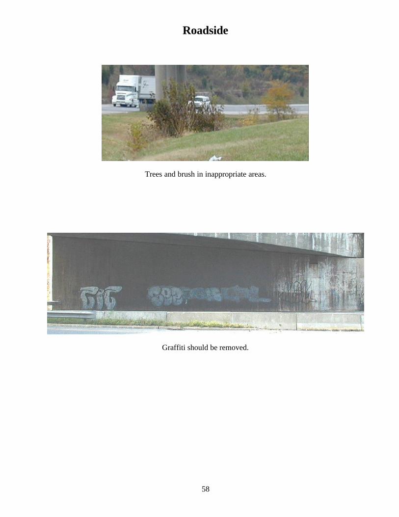
Trees and brush in inappropriate areas.
Graffiti should be removed.

Roadside
59
Fences should be functional and in good repair.
Sidewalks and paved approaches.

Roadside
60
Sidewalks should provide a safe environment for pedestrians.
Slope failure.

Roadside
61
Slides tend to block drainage ditches, provide for uneven slopes, and create unpleasant aesthetics.
Well maintained turf.

Roadside
62
Median in rural location.
Lack of vegetative cover leads to erosion, which creates washouts and pollutes the water leaving the right-of-way.

Traffic Control
63
Traffic signs direct and instruct motorists. Damaged or non-reflective signs are difficult to interpret, especially at night.
Traffic signs should stand erect. Signs posts that lean create an unpleasant appearance.

Traffic Control
64
Signposts can be checked for vertical alignment with a carpenter's level.
Delineators.

Traffic Control
65
Delineators.
Delineator.

Traffic Control
66
Barrier wall exhibiting structural distress.
Guardrail.

Traffic Control
67
End treatment.
Guard cable.

Traffic Control
68
Impact attenuators.
Pavement marking.

Traffic Control
69
Highway lighting.


![Transportation Indicators For Sustainabilitycourses.washington.edu/cee587/Readings/sustainability.pdf · Board’s Sustainable Transportation Indicators Subcommittee (ADD40[1]), the](https://static.fdocuments.us/doc/165x107/5e15839009933f25ad1382b9/transportation-indicators-for-s-boardas-sustainable-transportation-indicators.jpg)


