Percon Program Generator
150
DRAFT—12/16/96 D:\DOCS\PPG\COVER.FMD 1720 Willow Creek Circle Suite 530 Eugene, OR 97402-9171 541-344-1189 FAX 541-344-1399 00-655-01 1/96 Percon Program Generator Version 3.5 User Manual
Transcript of Percon Program Generator

DRAFT—12/16/96D:\DOCS\PPG\COVER.FMD
1720 Willow Creek CircleSuite 530
Eugene, OR 97402-9171541-344-1189
FAX 541-344-1399
00-655-011/96
Percon Program GeneratorVersion 3.5
User Manual

DRAFT—12/16/96D:\DOCS\PPG\COPYRITE.FMD
© 1994
Percon, Inc.1720 Willow Creek CircleSuite 530Eugene, OR 97402-9171
(503) 344-1189(503) 344-1399 FAX
All rights reserved. No part of this work may be reproduced, transmitted, or stored in any form or by any means without prior written consent, except by a reviewer, who may quote brief passages in a review, or as provided for in the Copyright Act of 1976.
Percon® is a registered trademark of Percon Acquisition, Inc. Percon Program Generator™, PPG™, PocketReader™, and PT 2000™ are trademarks of Percon Acquisition, Inc.
Microsoft® and MS-DOS® are registered trademarks of Microsoft Corporation. Windows™ is a trademark of Microsoft Corporation.
IBM®, IBM PC®, and PC-DOS® are registered trademarks of International Business Machines Corporation.
All other product names are trademarks or registered trademarks of their manufacturers.
Many of the designations used by manufacturers and sellers to distinguish their products are claimed as trademarks. Where these designations appear here and the authors were aware of a trademark claim, the designations have been printed with a trademark (™) symbol.
SOFTWARE LICENSE:Percon grants the purchaser the right to use one copy of the Percon Program Generator (PPG) software on one computer. The purchaser is hereby licensed to read the program from its medium into the memory of the computer for the purpose of executing the program or to copy the program for the purpose of archival backup or convenient access, provided such copies are made solely in support of the purchaser's operation of the program on a single computer.
COPYRIGHT:Percon Program Generator (PPG) is owned by Percon and is protected by United States copyright laws and international treaty provisions. Therefore, you must treat PPG like any other copyrighted material (e.g., a book), except that you may either (a) make one copy of PPG solely for backup or archival purposes, or (b) transfer PPG to a single hard disk, provided you keep the original solely for backup or archival purposes. Copying (except as mentioned above), duplicating, selling, or otherwise distributing this product is a violation of Federal Copyright Law.
The information contained in this document is subject to change without notice.

iii
DRAFT—12/16/96D:\DOCS\PPG\PPG.TOC
*CONCONTENTS*CONTENTS*CONTENTS*CONTENTS*CONTENTS*CONTENTS*CONTENTS*CONTENTS*CONTENTS*CONTENTS*Contents
Introduction . . . . . . . . . . . . . . . . . . . . . . . . . . . . . . . . . . . . . . . . . . . . . . . . . . . . . . . 1Equipment Requirements . . . . . . . . . . . . . . . . . . . . . . . . . . . . . . . . . . . . . . . . . . . . . . 2Before You Start . . . . . . . . . . . . . . . . . . . . . . . . . . . . . . . . . . . . . . . . . . . . . . . . . . . . . 2How to Use This Manual . . . . . . . . . . . . . . . . . . . . . . . . . . . . . . . . . . . . . . . . . . . . . . 2
Typographic Conventions . . . . . . . . . . . . . . . . . . . . . . . . . . . . . . . . . . . . . . . . . . . 3Technical Support . . . . . . . . . . . . . . . . . . . . . . . . . . . . . . . . . . . . . . . . . . . . . . . . . . . 4
CHAPTER 1: Getting Started . . . . . . . . . . . . . . . . . . . . . . . . . . . . . . . . . . . . . . . . . . . . . . . . . . . . . 5Installing PPG . . . . . . . . . . . . . . . . . . . . . . . . . . . . . . . . . . . . . . . . . . . . . . . . . . . . . . 5Loading and Exiting PPG . . . . . . . . . . . . . . . . . . . . . . . . . . . . . . . . . . . . . . . . . . . . . . 6An Overview . . . . . . . . . . . . . . . . . . . . . . . . . . . . . . . . . . . . . . . . . . . . . . . . . . . . . . . . 7Sample Program Files . . . . . . . . . . . . . . . . . . . . . . . . . . . . . . . . . . . . . . . . . . . . . . . . 8
CHAPTER 2: Tutorial . . . . . . . . . . . . . . . . . . . . . . . . . . . . . . . . . . . . . . . . . . . . . . . . . . . . . . . . . . . 9Studying a Sample Program . . . . . . . . . . . . . . . . . . . . . . . . . . . . . . . . . . . . . . . . . . 10Programming Your Portable . . . . . . . . . . . . . . . . . . . . . . . . . . . . . . . . . . . . . . . . . . . 15
Box: If You Have Problems . . . . . . . . . . . . . . . . . . . . . . . . . . . . . . . . . . . . . . . . . 16Uploading Bar Code Data . . . . . . . . . . . . . . . . . . . . . . . . . . . . . . . . . . . . . . . . . . . . 16Building Your Own Portable Program . . . . . . . . . . . . . . . . . . . . . . . . . . . . . . . . . . . . 18
Creating Frames and Links. . . . . . . . . . . . . . . . . . . . . . . . . . . . . . . . . . . . . . . . . 18Creating the Main Menu Nodes . . . . . . . . . . . . . . . . . . . . . . . . . . . . . . . . . . . . . 20Saving Your Program . . . . . . . . . . . . . . . . . . . . . . . . . . . . . . . . . . . . . . . . . . . . . 23Creating and Setting Up the Collect Data Nodes . . . . . . . . . . . . . . . . . . . . . . . . 24
The Display : Enter Item Node . . . . . . . . . . . . . . . . . . . . . . . . . . . . . . . . . . 26The Input : Item Node . . . . . . . . . . . . . . . . . . . . . . . . . . . . . . . . . . . . . . . . . 26The Verify : Input Node . . . . . . . . . . . . . . . . . . . . . . . . . . . . . . . . . . . . . . . . 29The Output : Error Beep Node . . . . . . . . . . . . . . . . . . . . . . . . . . . . . . . . . . 30The Display : Error Text Node . . . . . . . . . . . . . . . . . . . . . . . . . . . . . . . . . . . 30The Copy : To File Node . . . . . . . . . . . . . . . . . . . . . . . . . . . . . . . . . . . . . . . 31

Contents
iv Percon Program Generator User Manual
DRAFT—12/16/96D:\DOCS\PPG\PPG.TOC
Creating and Setting Up the Upload Data Nodes . . . . . . . . . . . . . . . . . . . . . . . . 32The Menu : Confirmation Node . . . . . . . . . . . . . . . . . . . . . . . . . . . . . . . . . . 33The Output : to PC Node . . . . . . . . . . . . . . . . . . . . . . . . . . . . . . . . . . . . . . . 34The Output : Error Beep Node . . . . . . . . . . . . . . . . . . . . . . . . . . . . . . . . . . 34The Menu : Error Text Node . . . . . . . . . . . . . . . . . . . . . . . . . . . . . . . . . . . . 35The Display : Successful Node . . . . . . . . . . . . . . . . . . . . . . . . . . . . . . . . . . 35The Input : Timeout Display Node . . . . . . . . . . . . . . . . . . . . . . . . . . . . . . . . 36The Modify : Erase File Node . . . . . . . . . . . . . . . . . . . . . . . . . . . . . . . . . . . 36
Emulating the Program . . . . . . . . . . . . . . . . . . . . . . . . . . . . . . . . . . . . . . . . . . . . . . . 37Loading and Using the Program . . . . . . . . . . . . . . . . . . . . . . . . . . . . . . . . . . . . . . . 40
Box: If You Have Problems . . . . . . . . . . . . . . . . . . . . . . . . . . . . . . . . . . . . . . . . . 41Uploading Data from the Portable . . . . . . . . . . . . . . . . . . . . . . . . . . . . . . . . . . . . . . 42Creating and Using Templates . . . . . . . . . . . . . . . . . . . . . . . . . . . . . . . . . . . . . . . . . 43
Creating the New Nodes. . . . . . . . . . . . . . . . . . . . . . . . . . . . . . . . . . . . . . . . . . . 44Creating the Fields . . . . . . . . . . . . . . . . . . . . . . . . . . . . . . . . . . . . . . . . . . . . . . . 46
CHAPTER 3: User’s Guide . . . . . . . . . . . . . . . . . . . . . . . . . . . . . . . . . . . . . . . . . . . . . . . . . . . . . . 49Using Online Help . . . . . . . . . . . . . . . . . . . . . . . . . . . . . . . . . . . . . . . . . . . . . . . . . . 50Using the Mouse . . . . . . . . . . . . . . . . . . . . . . . . . . . . . . . . . . . . . . . . . . . . . . . . . . . 51Generating a Portable Program . . . . . . . . . . . . . . . . . . . . . . . . . . . . . . . . . . . . . . . . 52
Flow Chart Levels . . . . . . . . . . . . . . . . . . . . . . . . . . . . . . . . . . . . . . . . . . . . . . . . 52Testing Your Program . . . . . . . . . . . . . . . . . . . . . . . . . . . . . . . . . . . . . . . . . . . . . 53
Creating Frames . . . . . . . . . . . . . . . . . . . . . . . . . . . . . . . . . . . . . . . . . . . . . . . . . . . . 53Creating Subroutines . . . . . . . . . . . . . . . . . . . . . . . . . . . . . . . . . . . . . . . . . . . . . . . . 54Creating and Using Links . . . . . . . . . . . . . . . . . . . . . . . . . . . . . . . . . . . . . . . . . . . . . 56
Creating Links. . . . . . . . . . . . . . . . . . . . . . . . . . . . . . . . . . . . . . . . . . . . . . . . . . . 56Adjusting Links . . . . . . . . . . . . . . . . . . . . . . . . . . . . . . . . . . . . . . . . . . . . . . . . . . 57Deleting Links . . . . . . . . . . . . . . . . . . . . . . . . . . . . . . . . . . . . . . . . . . . . . . . . . . . 57
Creating and Using Nodes . . . . . . . . . . . . . . . . . . . . . . . . . . . . . . . . . . . . . . . . . . . . 57Call Nodes . . . . . . . . . . . . . . . . . . . . . . . . . . . . . . . . . . . . . . . . . . . . . . . . . . . . . 58Copy Nodes . . . . . . . . . . . . . . . . . . . . . . . . . . . . . . . . . . . . . . . . . . . . . . . . . . . . 59Display Nodes. . . . . . . . . . . . . . . . . . . . . . . . . . . . . . . . . . . . . . . . . . . . . . . . . . . 60Input Nodes . . . . . . . . . . . . . . . . . . . . . . . . . . . . . . . . . . . . . . . . . . . . . . . . . . . . 60
Box: Echoing Input . . . . . . . . . . . . . . . . . . . . . . . . . . . . . . . . . . . . . . . . . . . . 62Math Nodes . . . . . . . . . . . . . . . . . . . . . . . . . . . . . . . . . . . . . . . . . . . . . . . . . . . . 63Menu Nodes . . . . . . . . . . . . . . . . . . . . . . . . . . . . . . . . . . . . . . . . . . . . . . . . . . . . 64Modify Nodes . . . . . . . . . . . . . . . . . . . . . . . . . . . . . . . . . . . . . . . . . . . . . . . . . . . 65Output Nodes . . . . . . . . . . . . . . . . . . . . . . . . . . . . . . . . . . . . . . . . . . . . . . . . . . . 67
Box: Outputting Commands to the System . . . . . . . . . . . . . . . . . . . . . . . . . 68Verify Nodes . . . . . . . . . . . . . . . . . . . . . . . . . . . . . . . . . . . . . . . . . . . . . . . . . . . . 69
Box: Specifying a Range to Match . . . . . . . . . . . . . . . . . . . . . . . . . . . . . . . . 70Controlling Data Flow . . . . . . . . . . . . . . . . . . . . . . . . . . . . . . . . . . . . . . . . . . . . . . . . 71
Registers. . . . . . . . . . . . . . . . . . . . . . . . . . . . . . . . . . . . . . . . . . . . . . . . . . . . . . . 72Using a Register as a Source . . . . . . . . . . . . . . . . . . . . . . . . . . . . . . . . . . . 72Using a Register as a Destination . . . . . . . . . . . . . . . . . . . . . . . . . . . . . . . . 72Specifying a Register Field . . . . . . . . . . . . . . . . . . . . . . . . . . . . . . . . . . . . . 73

Contents
Percon Program Generator User Manual v
DRAFT—12/16/96D:\DOCS\PPG\PPG.TOC
Files . . . . . . . . . . . . . . . . . . . . . . . . . . . . . . . . . . . . . . . . . . . . . . . . . . . . . . . . . . 73Using a File as a Source . . . . . . . . . . . . . . . . . . . . . . . . . . . . . . . . . . . . . . . 73Using a File as a Destination . . . . . . . . . . . . . . . . . . . . . . . . . . . . . . . . . . . 74
Creating a Template . . . . . . . . . . . . . . . . . . . . . . . . . . . . . . . . . . . . . . . . . . . . . . 74Modifying a Pick List . . . . . . . . . . . . . . . . . . . . . . . . . . . . . . . . . . . . . . . . . . . . . . 77Breaking Down Data in a Register . . . . . . . . . . . . . . . . . . . . . . . . . . . . . . . . . . . 78
Editing a Flow Chart . . . . . . . . . . . . . . . . . . . . . . . . . . . . . . . . . . . . . . . . . . . . . . . . . 79Cutting, Copying, and Pasting . . . . . . . . . . . . . . . . . . . . . . . . . . . . . . . . . . . . . . 79Deleting Nodes and Frames . . . . . . . . . . . . . . . . . . . . . . . . . . . . . . . . . . . . . . . . 80Renaming Nodes and Frames . . . . . . . . . . . . . . . . . . . . . . . . . . . . . . . . . . . . . . 80
General Options . . . . . . . . . . . . . . . . . . . . . . . . . . . . . . . . . . . . . . . . . . . . . . . . . . . . 81Switching Display Size . . . . . . . . . . . . . . . . . . . . . . . . . . . . . . . . . . . . . . . . . . . . 81Changing Fonts . . . . . . . . . . . . . . . . . . . . . . . . . . . . . . . . . . . . . . . . . . . . . . . . . 82Adjusting the Grid and Box Size . . . . . . . . . . . . . . . . . . . . . . . . . . . . . . . . . . . . . 82Specifying Bar Code Type . . . . . . . . . . . . . . . . . . . . . . . . . . . . . . . . . . . . . . . . . 83Setting a Starting Place . . . . . . . . . . . . . . . . . . . . . . . . . . . . . . . . . . . . . . . . . . . 84
Working with Program Source Files . . . . . . . . . . . . . . . . . . . . . . . . . . . . . . . . . . . . . 84Opening a File . . . . . . . . . . . . . . . . . . . . . . . . . . . . . . . . . . . . . . . . . . . . . . . . . . 85Saving a File . . . . . . . . . . . . . . . . . . . . . . . . . . . . . . . . . . . . . . . . . . . . . . . . . . . . 86Starting a New File . . . . . . . . . . . . . . . . . . . . . . . . . . . . . . . . . . . . . . . . . . . . . . . 86Printing a File . . . . . . . . . . . . . . . . . . . . . . . . . . . . . . . . . . . . . . . . . . . . . . . . . . . 87
Using the Program Emulator . . . . . . . . . . . . . . . . . . . . . . . . . . . . . . . . . . . . . . . . . . 87The Emulation Window. . . . . . . . . . . . . . . . . . . . . . . . . . . . . . . . . . . . . . . . . . . . 87Emulation Menu Options . . . . . . . . . . . . . . . . . . . . . . . . . . . . . . . . . . . . . . . . . . 88Setting Breakpoints. . . . . . . . . . . . . . . . . . . . . . . . . . . . . . . . . . . . . . . . . . . . . . . 89Watching Register Contents . . . . . . . . . . . . . . . . . . . . . . . . . . . . . . . . . . . . . . . . 90Tracing Program Execution. . . . . . . . . . . . . . . . . . . . . . . . . . . . . . . . . . . . . . . . . 91
Downloading a Program . . . . . . . . . . . . . . . . . . . . . . . . . . . . . . . . . . . . . . . . . . . . . . 92Box: If You Have Problems . . . . . . . . . . . . . . . . . . . . . . . . . . . . . . . . . . . . . . . . . 93
Transferring Data to and from the Portable . . . . . . . . . . . . . . . . . . . . . . . . . . . . . . . 93Using PTFER . . . . . . . . . . . . . . . . . . . . . . . . . . . . . . . . . . . . . . . . . . . . . . . . . . . 94
Setting Options . . . . . . . . . . . . . . . . . . . . . . . . . . . . . . . . . . . . . . . . . . . . . . 96Setting Command Line Options . . . . . . . . . . . . . . . . . . . . . . . . . . . . . . . . . 97
Using PDTFER . . . . . . . . . . . . . . . . . . . . . . . . . . . . . . . . . . . . . . . . . . . . . . . . . . 98USING MACTFER . . . . . . . . . . . . . . . . . . . . . . . . . . . . . . . . . . . . . . . . . . . . . . . 98Using updtfer . . . . . . . . . . . . . . . . . . . . . . . . . . . . . . . . . . . . . . . . . . . . . . . . . . . 99
CHAPTER 4: Example Frames . . . . . . . . . . . . . . . . . . . . . . . . . . . . . . . . . . . . . . . . . . . . . . . . . . 101Setting the Date and Time . . . . . . . . . . . . . . . . . . . . . . . . . . . . . . . . . . . . . . . . . . . 102Changing the Auto Off Setting . . . . . . . . . . . . . . . . . . . . . . . . . . . . . . . . . . . . . . . . 103Displaying the Contents of a Register . . . . . . . . . . . . . . . . . . . . . . . . . . . . . . . . . . 103Verifying Input Size . . . . . . . . . . . . . . . . . . . . . . . . . . . . . . . . . . . . . . . . . . . . . . . . 105Downloading a File to a Percon Portable . . . . . . . . . . . . . . . . . . . . . . . . . . . . . . . . 107Finding the Number of Records in a File . . . . . . . . . . . . . . . . . . . . . . . . . . . . . . . . 109Searching for a Partial Match . . . . . . . . . . . . . . . . . . . . . . . . . . . . . . . . . . . . . . . . . 110Splitting Records into Two Files . . . . . . . . . . . . . . . . . . . . . . . . . . . . . . . . . . . . . . . 111

Contents
vi Percon Program Generator User Manual
DRAFT—12/16/96D:\DOCS\PPG\PPG.TOC
Referencing Two Different Files . . . . . . . . . . . . . . . . . . . . . . . . . . . . . . . . . . . . . . . 113Reviewing a File . . . . . . . . . . . . . . . . . . . . . . . . . . . . . . . . . . . . . . . . . . . . . . . . . . . 115Sounding a Beep . . . . . . . . . . . . . . . . . . . . . . . . . . . . . . . . . . . . . . . . . . . . . . . . . . 117Converting the PT 2000 into a Wedge . . . . . . . . . . . . . . . . . . . . . . . . . . . . . . . . . . 117Padding a Number with Leading Zeros . . . . . . . . . . . . . . . . . . . . . . . . . . . . . . . . . 118
APPENDIX A: Error Messages . . . . . . . . . . . . . . . . . . . . . . . . . . . . . . . . . . . . . . . . . . . . . . . . . . 121
APPENDIX B: Warranty Information . . . . . . . . . . . . . . . . . . . . . . . . . . . . . . . . . . . . . . . . . . . . . . 123
APPENDIX C: ASCII Table. . . . . . . . . . . . . . . . . . . . . . . . . . . . . . . . . . . . . . . . . . . . . . . . . . . . . . . 124
APPENDIX D: The PPG Library . . . . . . . . . . . . . . . . . . . . . . . . . . . . . . . . . . . . . . . . . . . . . . . . . . 125
APPENDIX E: Useful Bar Codes . . . . . . . . . . . . . . . . . . . . . . . . . . . . . . . . . . . . . . . . . . . . . . . . . 129
Glossary. . . . . . . . . . . . . . . . . . . . . . . . . . . . . . . . . . . . . . . . . . . . . . . . . . . . . . . . . 131
Index. . . . . . . . . . . . . . . . . . . . . . . . . . . . . . . . . . . . . . . . . . . . . . . . . . . . . . . . . . . . 135

1
DRAFT—12/16/96D:\DOCS\PPG\INTRO.FMD
*I*INTRODUCTION*INTRODUCTION*INTRODUCTION*INTRODUCTION*INTRODUCTION*INTRODUCTION*INTRODUCTION*Introduction
Percon Program Generator (PPG) is a Windows™ application that you can use to createindividualized programs for the Percon® family of portables. Rather than requiring use of acomplicated programming language, PPG provides an easy-to-follow user interface thatcreates the program for you. You use menu commands and dialog boxes to build a flowchart of the steps you want to include. PPG translates the flow chart into a program thatcan be loaded into the portable.
You can use PPG to specify
• The text that appears in the portable's display area.
• The options that can be selected with the portable's function keys.
• The types of bar codes the portable can read.
• How the portable will accept input—via the scanner (wand), the input keys, the serialport, or a combination of input sources.
• Where the portable stores data that is input.
• What to do if the wrong data or type of data is entered.
• How to format collected data for transfer to a PC file.
PPG makes it possible to customize your portable so that it suits your purposes exactly.You can use any of the sample program files that are available (see appendix D), modifyan existing program, or create a program of your own from scratch.

Introduction
2 Percon Program Generator User Manual
DRAFT—12/16/96D:\DOCS\PPG\INTRO.FMD
Equipment RequirementsThe following equipment is required to run PPG:
• An IBM PC or compatible computer with a 286 or better processor
• At least 1 megabyte of RAM (random access memory)
• At least 2 megabytes of hard disk space available
• A high-density, floppy disk drive (either 5¼" or 3½")
• A mouse
• DOS version 3.1 or later
• Microsoft® Windows version 3.0 or later
• A serial port (for loading your program into a portable)
You must have Microsoft Windows installed on your system. If it is not, install it followingthe directions in your Microsoft Windows user’s guide. PPG runs only in Windows en-hanced or standard mode, not in real mode.
Before You StartReview the license agreement printed on the inside front cover of this manual and on theenvelope containing the program disk. It gives you permission to copy the program files forbackup purposes only. You may not make a copy for another person to use.
Also, fill out and mail the enclosed registration card. As a registered owner of the PPG pro-gram, you’ll be eligible for technical support and will be notified of program upgrades.
How to Use This ManualThis manual is divided into four chapters:
• Chapter 1, “Getting Started,” tells you how to install PPG on your hard disk and load itinto Windows. It gives you an overview of PPG concepts and usage and describes thesample programs that come with PPG.
• Chapter 2, “Tutorial,” takes you step by step through the process of building a portableprogram. By following the detailed instructions, you will create a simple program, use theprogram emulator to debug the program, and load the program into a portable. Afterscanning sample bar codes, you will then transfer the collected data back to your PC.
• Chapter 3, “User’s Guide,” gives you detailed information about using PPG. After read-ing through it, you can use it as a reference whenever you use PPG.
• Chapter 4, “Example Frames,” offers several ideas for PPG programs you can create.

Typographic Conventions
Percon Program Generator User Manual 3
DRAFT—12/16/96D:\DOCS\PPG\INTRO.FMD
Appendixes at the end of the manual explain error messages you might encounter, giveyou warranty information, provide an ASCII table for reference, describe files that comewith PPG, and provide several useful bar codes you can scan whenever necessary. Aglossary contains definitions of technical terms used in this manual.
Ideally, you should read this manual from front to back. The tutorial will give you a goodsense of what you need to do to create and use a portable program. The user's guide pro-vides the details you need to do it. The example frames give additional helpful information.Once you've read through the manual, you may want to return to the user's guide chapterperiodically to refresh your memory.
This manual assumes that you are familiar with Microsoft Windows. If you do not knowhow to launch applications, select menu options, or use dialog boxes, refer to yourMicrosoft Windows documentation.
Typographic Conventions
This manual presents special items in the text in the following ways:
• Words in italics are important terms you should know. Many of these terms are definedin the glossary at the back of the manual.
• Words in bold are selections that appear in the PPG program, such as frame names,node names, menu options, and fields and buttons in dialog boxes.
• Words in underlined bold are selections that you should make. These appear through-out the tutorial and in other places where you are instructed to take action.
• Words in underlined bold separated by an arrow (ð) are selections that you shouldmake in the specific order given. For example, FileðRun means select the File menuand then select Run from that menu.
• Characters in courier bold are input characters that you should type. Input charac-ters are usually given in lowercase (no capital letters), but you may enter them in lower-case, uppercase, or a combination. When input characters are given in uppercase or acombination of lowercase and uppercase, type the characters exactly as shown.
• Characters in SMALL CAPITAL LETTERS are file names or directories.
• Characters in BOLD SMALL CAPITAL LETTERS are keyboard keys, such as ENTER. Whenthese are linked with a plus sign (for example, SHIFT+ENTER), hold down the first keywhile pressing the second key once.

Introduction
4 Percon Program Generator User Manual
DRAFT—12/16/96D:\DOCS\PPG\INTRO.FMD
Technical SupportIf you have a question or problem that you are unable to resolve by reading the manual oronline help, you can call Percon Technical Support for assistance. Before you do so, how-ever, be prepared to offer the following information:
• Your name and address.
• The program's version number (choose HelpðAbout PPG for this).
• The dates of the *.PHB and *.BHB files that came with PPG. (Use the File Manager or theDOS DIR command for this.)
• The versions of DOS and Windows you are using. (Type ver at the DOS prompt for theDOS version number. Choose HelpðAbout Program Manager from the Windows Pro-gram Manager for the Windows version number.)
• The amount of RAM and extended or expanded memory installed. (If you have DOS ver-sion 4.0 or later, type mem at the DOS prompt for this.)
• The amount of free space on your hard disk. (If you have DOS version 4.0 or later, typedir at the DOS prompt for this.)
• A list of all peripherals installed, such as a serial mouse, printer, or modem.
• The contents of your CONFIG.SYS and AUTOEXEC.BAT files. (Use a Windows utility to viewthese, or enter type filename.ext at the DOS prompt in the root directory.Replace filename.ext with the name and extension of the file you want to read.)
• Your computer make and model.
• A concise, clear description of the problem, including any error messages that weredisplayed.
To contact Percon Technical Support, call 503-344-1189 between 8 a.m. and 5 p.m.Pacific time, Monday through Friday. If you prefer to correspond by letter, fax the TechnicalSupport Department at 503-344-1399 or write to:
Percon IncorporatedTechnical Support Dept.1720 Willow Creek Circle, Suite 530Eugene, OR 97402-9171

5
DRAFT—12/16/96 1:57pmD:\DOCS\PPG\CH1.FMD
Chapter 1
*GETTING*STARTED*GETTING*STARTED*GETTING*STARTED*GETTING*STARTED*GETTING*STARTEDVb*Getting Started
This chapter helps you prepare to use Percon Program Generator (PPG). It tells you howto install the application on your hard disk and load and exit the program. It gives you anoverview of the application and how it integrates with your Percon portable. Finally, it de-scribes three sample program files that come with PPG.
Installing PPGThe PPG installation program automatically creates a subdirectory on your hard disk,copies your PPG files to it, and creates a program group for the application in Windows. Torun the installation program, complete the following steps:
1. Start Windows in either enhanced or standard mode.
2. Insert the PPG program disk in drive A.
If you use a floppy drive other than A, substitute its letter for A.
3. From the Windows Program Manager, select FileðRun.
4. In the Run dialog box, type a:install and press ENTER or select OK.

Chapter 1: Getting Started
6 Percon Program Generator User Manual
DRAFT—12/16/96 1:57pmD:\DOCS\PPG\CH1.FMD
The installation program copies the PPG files to a subdirectory named \PPG31 off the rootdirectory of your hard disk. You can specify another directory during the installation, but itmust be immediately off the root directory (for example, \MYPPG). also creates a new pro-gram group in your Windows Program Manager. The Percon PPG31 program group con-tains the following items:
Loading and Exiting PPGTo work with PPG, select the PPG icon in the Percon PPG31 program group in Windows.The PPG window appears, as shown in figure 1-1.
PPG is the Percon Program Generator application. This is theapplication you'll use to create programs for your Percon portable.
PROG is used to transfer the program you created in PPG to theportable. This utility is called automatically by PPG when you downloada program to the portable.
PTFER is used to transfer data between a PC and the portable. Afteryou've scanned bar codes with the portable, you can use this utility toupload the data into a file on your PC. You can also use it to downloadinformation stored in a PC file into the portable.
Figure 1-1. The PPG window
Control-menu box
Maximize button
Minimize button

An Overview
Percon Program Generator User Manual 7
DRAFT—12/16/96 1:57pmD:\DOCS\PPG\CH1.FMD
You can use the Windows “drag-and-drop” technique to load PPG and a program sourcefile at the same time. Just use the mouse to drag the icon for the file from the Windows FileManager onto the PPG icon.
To expand the window to fill the screen, select the Maximize button (see figure 1-1).
To temporarily remove the PPG window from your screen without exiting the application,select the Minimize button (see figure 1-1). The window becomes an application icon atthe bottom of the Windows desktop. Double-click on the icon to bring the window back ex-actly as you left it.
To exit PPG, select FileðExit from the menu or double-click on the Control-menu box(see figure 1-1). A dialog box appears, asking if you want to save any changes to the cur-rent file. Select Yes to save changes or No to discard them.
For further information on working in application windows, including using scroll bars andselecting menu commands, refer to your Windows documentation.
An OverviewPPG helps you program your Percon portable to collect and store data in exactly the wayyou want. Creating the program is only one part of the process, however. There are actu-ally several steps involved:
Generating the Program This involves using PPG to create a flow chart of the data-collection process. Details of each step in the program are given in dialog boxes attachedto individual pieces of the flow chart.
Emulating the Program This is an optional step, but it can be helpful in testing a newprogram. It uses a special Emulation window that simulates the effects of a program asyou run it. You can see text displayed on a model portable screen, simulate data input, and“press” function keys. You can also view the contents of specified registers, set break-points at which to pause program execution, and view a “Trace” window that lists actionstaken. If there are problems with the program, you can correct them before you load theprogram into your portable.
Downloading the Program Once your program is complete, you can connect yourPercon portable to your PC via a supplied cable and use the Download Program com-mand to load the program into it. PPG compiles the program first, translating it into codethat is understood by the portable, and then sends the program over the cable to the por-table. When it's done, you're ready to collect data using the portable.
Chapter 1: Getting Started
8 Percon Program Generator User Manual
DRAFT—12/16/96 1:57pmD:\DOCS\PPG\CH1.FMD
Transferring Data After you've scanned a series of bar codes with the programmed por-table, you can use the PTFER or PDTFER program that comes with PPG to transfer thecollected data to a file on your PC. The information is sent back through the connectedcable to a specified file on your computer. You can also transfer data, such as a “pick list”for comparing input data, from the PC to the portable. Versions of this transfer program arealso available for Macintosh and UNIX computer systems (see chapter 4).
Most likely, the data you collect and store in a file will be nothing more than a series ofnumbers or alphanumeric strings. You can transfer that data, however, into a data proc-essing program that makes sense of it. For example, a scanned bar code may read 107-028-0274. However, once that number is fed through a database or some other programset up to interpret it, it could be translated into more readable information, such asDECKERS THONG-ADULT, BLACK BRAID, $25.60.
Although it is possible to program the portable to translate scanned numbers into words,this is usually a function of the program you use to process the data. You may load thedata into a spreadsheet program, for example, that you can use to perform calculations. Oryou might use a database program that keeps track of each item in your inventory. You canuse PPG to format collected data in a style that is accepted by most data processing pro-grams.
Sample Program FilesPPG comes with three important sample files:
• SAMPLE.SCR allows you to collect information with your portable, upload collected data toa PC, and erase collected data. You will be using this file as you work through chapter 2.
• SAMPLE2.SCR is a simple but complete data-collection program that allows the user toenter data as either item-and-quantity values or just item values. The program alsostores data, uploads data, and erases data.
• SAMPLE3.SCR is an expanded version of SAMPLE2.SCR that includes review and editcapabilities. (This is the program that was loaded with your portable when you first gotit.)
You can use these files as is or modify them to suit your needs.
Several additional sample files are available from your PPG dealer (see appendix D).Some of these files are just portions of programs demonstrating use of a specific node.However, you can use any of these samples as a foundation for building a full-sizeprogram.

9
DRAFT—12/16/96 1:57pmD:\DOCS\PPG\CH2.FMD
Chapter 2
*TUTORIAL*TUTORIAL*TUTORIAL*TUTORIAL*TUTORIAL*TUTORIAL*TUTORIAL*TUTORIAL*TUTORIALTutorial
This chapter eases you into using Percon Program Generator (PPG) by stepping youthrough several specific procedures. Detailed instructions have you perform the following:
• View the flow chart of a sample program file.
• Load the program into your portable, collect data using the program, and upload thedata to your PC.
• Build a portable program of your own using PPG. The program will allow you to collectand upload data using your portable.
• Use the Emulation window to debug your portable program.
• Load the new program into your portable and use it to scan bar codes.
• Upload the collected bar code data to a file on your PC.
• Create a template that divides a register into fields so that different types of values(quantity and item) can be stored together as value pairs.
The entire tutorial should take approximately two hours to complete. Optional breaks areinserted between sections, with instructions on saving and reloading your work. If youcan't complete the tutorial in one sitting, it's best if you stop at one of these points.
When you're done, you should have a solid understanding of the steps involved in pro-gramming and uploading data from the portable. You can then refer to chapter 3 for detailson creating your own customized portable program.

Chapter 2: Tutorial
10 Percon Program Generator User Manual
DRAFT—12/16/96 1:57pmD:\DOCS\PPG\CH2.FMD
Studying a Sample ProgramThe easiest way to find out how a portable program works is to study an existing one. PPGcomes with three sample program files. We will take a look at the simplest of the three.Later, you will load it into your portable and collect and upload data with it.
Complete the following steps to see how a sample program works:
1. If you're not already in PPG, start it now by going into the Percon PPG31 programgroup in Windows and double-clicking on the PPG icon.
2. Click on the Maximize button at the right end of the title bar to expand the PPG win-dow to a full screen.
3. Choose FileðOpen and select sample.scr from the displayed list of files in theC:\PPG31 directory. Select OK to load the file into the PPG window (see figure 2-1).
The program is initially shown at what is called the Frames level. This level contains aflow chart of the program's main functions. Each rectangle in the chart is called aframe. Most of the frames are linked together with arrows, indicating the flow of theprogram. This sample program includes a Main Menu that branches off into threetasks: collecting data, uploading data, and erasing data. Each of the tasks also allowsyou to return to the Main Menu.
Figure 2-1. A sample program file

Studying a Sample Program
Percon Program Generator User Manual 11
DRAFT—12/16/96 1:57pmD:\DOCS\PPG\CH2.FMD
The rectangle labeled “Pad Zeros” in the bottom-left corner is a subroutine. It doesn’tlink directly to the other frames, but it is jumped to from other parts of the program byCall nodes.
4. Move the mouse pointer to the Upload frame and click the right mouse button (orselect the frame and choose EditðRename from the menu). The Frame Name dialogbox will appear (see figure 2-2). This is where you define the text displayed in theframe.
You can also move to a frame by pressing the TAB key. The current frame is always indi-cated by a thick border. To select a frame, double-click on it with the left mouse button, ormove to it and then press the SPACEBAR.
5. Select Cancel or press ESC to close the dialog box.
6. Each program frame has its own sublevel flow chart, stored at the Nodes level. Thisenables you to break down a program into workable pieces, rather than dealing withone giant flow chart. Select the Main Menu frame to view its flow chart in the Nodeslevel (see figure 2-3).
Figure 2-2. The Frame Name dialog box
Figure 2-3. The Nodes level of the Main Menu frame

Chapter 2: Tutorial
12 Percon Program Generator User Manual
DRAFT—12/16/96 1:57pmD:\DOCS\PPG\CH2.FMD
At the Nodes level, each rectangle in a flow chart is called a node. Nodes give the pro-gram detailed instructions, such as where to store scanned data. A Menu node pre-sents a menu of options on the portable’s screen and specifies what actions will occurwhen the user presses function keys associated with those options. You specify theseinstructions by setting options in dialog boxes attached to the nodes.
7. Select the Display : Options node to view its dialog box (see figure 2-4).
8. Select Cancel or press ESC to exit the dialog box.
9. Select the Entry : Main Menu node (or any of the Exit To nodes) to return to theFrames level of the program. (Entry and Exit nodes have double-line borders.)
You can also use ViewðFrames and ViewðNodes in the menu to jump between levels.
10. Select the Collect frame to view its Nodes level (see figure 2-5).
Figure 2-4. The Display : Options dialog box
Figure 2-5. The Nodes level of the Collect frame

Studying a Sample Program
Percon Program Generator User Manual 13
DRAFT—12/16/96 1:57pmD:\DOCS\PPG\CH2.FMD
Two Display nodes prompt the user to scan or enter first an item code (Display :Enter Item) and then a quantity value (Display : Quantity). Both entered values aredisplayed together on the screen (via the Output nodes) and are then copied to a filefor storage (via the Copy node).
The Input nodes send control back to the Main Menu if a function key is pressed. TheCall node jumps to the Pad Zeros subroutine back in the Frames level, padding theinput value with zeros, if necessary, to meet a required number of digits.
11. Select either the Entry : Collect or Exit To : Main Menu node to go back to theFrames level.
12. Select the Upload frame to view the nodes involved in uploading collected data (seefigure 2-6).
13. Select either the Entry : Upload or Exit To : Main Menu node to go back to theFrames level.
14. Select the Erase frame to view the nodes involved in it (see figure 2-7).
Figure 2-6. The Nodes level of the Upload frame

Chapter 2: Tutorial
14 Percon Program Generator User Manual
DRAFT—12/16/96 1:57pmD:\DOCS\PPG\CH2.FMD
15. Select the Exit To : Main Menu node to return to the Frames level of the program.
16. The Pad Zeros subroutine (back in the Frames level) is called from within the Collectframe. It adds zeros to the front of a value to make it contain a given number of digits.Select the subroutine box to display its nodes (see figure 2-8).
Figure 2-7. The Nodes level of the Erase frame
Figure 2-8. The Nodes level of the Pad Zeros subroutine

Programming Your Portable
Percon Program Generator User Manual 15
DRAFT—12/16/96 1:57pmD:\DOCS\PPG\CH2.FMD
17. Select Return : Pad Zeros to return to the Frames level.
By looking at all the pieces of this program file, you can get a general idea of how the pro-gram is put together. The Frames flow chart defines the major tasks of the program: MainMenu, Collect, Upload, Erase, and Pad Zeros. Each frame and the subroutine is associ-ated with a more detailed flow chart at the Nodes level. Together, the frames, subroutine,and nodes work to outline every detail of the data-collection process.
Programming Your PortableTo use the program with your portable, you must download it from PPG to the portable.Complete the following steps:
1. If you're returning from a break and had exited PPG, start the program now by double-clicking its icon in the Window's Percon PPG31 program group.
2. Connect the 25-pin connector of your cable supplied with your portable to a serial porton your computer. (If you have a 9-pin serial port, use a 25-to-9-pin adapter.)
3. Connect the other end of the cable to your portable.
4. Turn the portable on.
5. In the PPG window, select FileðDownload Program from the menu. If a dialog boxappears asking whether you want to save changes to the file, select Cancel to keepthe sample file intact. (This will abort the download. Close the sample file without sav-ing it, reopen it, and select FileðDownload Program again.) If you do not have thesample file loaded, select it from the dialog box that appears.
The Percon Portable Compiler window appears momentarily as PPG compiles theprogram, translating it into a language understood by the portable.
While a program is downloading, you can work in another application window.
When compiling is complete, the Percon Portable Programmer window appears, dis-playing the message “Initiating Download.” If the connection is successful, the windowshows further messages as the program is loaded into the portable. The percentageof completion is displayed as the programming progresses.
When downloading is complete, the portable will beep. You'll see the message “Por-table successfully programmed” in the Percon Portable Programmer window, and theprogram's Main Menu will appear in the portable’s display.
Want a Break? If you're ready for a break, you can easily stop here. You haven'tmade any changes that need saving, so you won't lose any work ifyou exit PPG or turn off your computer.

Chapter 2: Tutorial
16 Percon Program Generator User Manual
DRAFT—12/16/96 1:57pmD:\DOCS\PPG\CH2.FMD
6. Double-click on the Percon Portable Programmer window's Control-menu box orselect FileðExit from the menu to close the window. (If downloading was unsuccess-ful, select Abort from the menu bar first.)
7. Double-click on the Percon Portable Compiler window's Control-menu box to close it.
Uploading Bar Code DataTry testing out the newly loaded program by scanning the bar codes that follow. (Removethe cable first, if you wish.) First press the F2 (Collect) button to prepare the portable toaccept data. After each code you scan, enter a quantity value by pressing a number key,and then press enter.
Now upload the collected data to your computer by completing the following steps:
If You Have Problems
If the message “Timeout Exceeded” appears or nothing happens atall, PPG was unable to make the connection with the portable. It maybe that your serial port is not COM2. Click on the Comm command inthe Percon Portable Programmer menu bar until it reflects the numberof your COM (communication) port. Then select the Download Pro-gram command again. (The COM setting is automatically stored withPPG and used the next time you download a program.)
Also, make sure that the cable is firmly connected at both ends. Youmight try resetting the portable by pressing SHIFT+ENTER
(ALPHA+ENTER on the PT 2000) while you reinsert the battery.
Depending on the program currently loaded into the portable, youmay need to scan the following bar code or select options in the por-table to place it in a mode for accepting downloaded data.
*/.*

Uploading Bar Code Data
Percon Program Generator User Manual 17
DRAFT—12/16/96 1:57pmD:\DOCS\PPG\CH2.FMD
1. Click on the Minimize button in the PPG window to put it out of sight temporarily.
2. Back in the Windows Program Manager, double-click on the PTFER icon in the PerconPPG31 program group. A blank PTFER window opens with three menu options: File,Options, and Help.
3. If your serial port is not COM2, select OptionsðSettings from the menu, select thecorrect COM port, and select Ok. (The setting is automatically stored with the PTFERprogram and is used the next time you transfer a file.)
4. Select OptionsðConnect to connect the program with the selected COM port. Amessage appears in the window, saying the connection was successful. (If you don'tsee this message, check the COM port setting. Make sure no other device is using theCOM port you specify, and try again.)
5. Select FileðReceive. In the Receive File dialog box, type data. This specifies a newfile named DATA, with the default extension of .TXT, as the destination for the uploadeddata. By default, the file is stored in the C:\PERCON\LIB directory, but you can alwaysspecify a different directory.
6. Select OK to return to the PTFER window. The name of the Receive file, DATA.TXT,should appear in the title bar.
7. If you disconnected the portable from the cable, reconnect it now.
8. Press F4 on the portable to return to the Main Menu, and then press F3 (for Upload) toprepare the portable for uploading data.
9. At the portable’s prompt for uploading data, press F3 (for Yes) to begin uploading.
10. The alphanumeric translations of the bar codes you scanned are stored in the filenamed DATA.TXT, and the message “File Received” appears in the PTFER window.
11. Select FileðExit to close the PTFER utility.
Once you've uploaded a file from the portable, you can put it to use with whatever applica-tion you use to work with scanned data. For example, you might have an application thattranslates the numbers and letters in the bar codes into meaningful text.
Want a Break? If you're ready for a break, you can easily stop here. You haven'tmade any changes that need saving, so you won't lose any work ifyou exit PPG or turn off your computer.

Chapter 2: Tutorial
18 Percon Program Generator User Manual
DRAFT—12/16/96 1:57pmD:\DOCS\PPG\CH2.FMD
Building Your Own Portable ProgramAt this point, you should understand the general concepts behind creating and loading aportable program, although many of the details have yet to be explained. In this section,you'll create a simple portable program from scratch. It will allow you to collect data withthe portable and upload it to your PC. A menu that appears when you turn on the portablegives you a choice of the two possible actions.
Creating Frames and Links
A program's frames define its general functions, such as collecting and uploading data.Links connecting frames indicate program flow—how you move from frame to frame. Thedetails for the program are contained in the Nodes level for each frame.
For your program, you will create three frames: Main Menu, Collect Data, and UploadData (see figure 2-9.). The program will start with the Main Menu frame, which offers ac-cess to the other frames. You can return to the Main Menu from either action frame.
Create the frames shown in figure 2-9 by completing the following steps:
1. To continue from the last section, double-click on the PPG icon at the bottom of theWindows desktop. If you took a break and exited PPG, restart the program now bydouble-clicking on its icon in the Window's Percon PPG31 program group. Click on theMaximize button, if necessary, to expand the window to fill the screen.
2. Select FileðNew to clear the workspace area so that you can create a new flow chart.(If prompted, answer No to saving changes.)
3. Select CreateðFrame to draw the first frame. The cursor turns into a rounded boxlabeled “FRAME”. Move it to the top-middle area of the workspace, and click the leftmouse button. A rectangle labeled “Frame1” appears at the cursor.
To adjust the position of a frame, just drag it with the mouse. To delete an unwanted frameor node, select it and then press DELETE.
Figure 2-9. The Frames level of the program

Creating Frames and Links
Percon Program Generator User Manual 19
DRAFT—12/16/96 1:57pmD:\DOCS\PPG\CH2.FMD
4. Click the right mouse button (or select the frame and choose EditðRename fromthe menu) to display the Frame Name dialog box. Type Main Menu in the input box,and press ENTER or select Ok. The frame now appears with the name “Main Menu.”
5. Now create the Collect Data frame. Select CreateðFrame, move the FRAME box tothe bottom left area of the workspace, and click the left mouse button. Open theFrame Name dialog box, type Collect Data, and select Ok.
6. Select CreateðFrame, move the FRAME box to the bottom right area of the work-space, and click the left mouse button. Open the Frame Name dialog box, typeUpload Data, and select Ok.
You now have the three frames of your program. Next, you need to create the arrows, orlinks, showing the flow of the program between the frames. Complete the following steps:
1. Select CreateðLink. The cursor turns into a rounded box labeled “LINK”.
2. Move the LINK box to the Main Menu frame and click the left mouse button.
3. Move the LINK box to the Collect Data frame and click the mouse again. An arrowappears, pointing from the Main Menu frame to the Collect Data frame.
4. Choose CreateðLink, click on the Main Menu frame, and then click on the UploadData frame. A second arrow appears.
The links you created give the user access to either the Collect Data or Upload Dataframe from within the Main Menu.
To adjust a link, exit Create mode and use the mouse to drag the link’s arrowhead. Todelete a link, drag its arrowhead to a blank area and double-click the left mouse button.
From each of the action frames, you want to give the user access to the Main Menu. Youneed to create links back to the Main Menu frame. This time you'll create jointed links thatbend at a 90 angle. Complete the following steps:
1. Select CreateðLink and click on the Collect Data frame.
2. Instead of clicking directly on the other frame, move the LINK box straight up until it islevel with the Main Menu frame, and then click the left mouse button.
3. Now move the pointer to the Main Menu frame and click the left mouse button. Ajointed line appears.
Jointed links work just like straight links, but they give you more flexibility in their place-ment. If a jointed link appears jagged, drag its joint until its lines are perpendicular.
4. Use the same method to create a jointed link from the Upload Data frame to the MainMenu frame.
Your screen should now look like the one shown in figure 2-9.
To redraw the screen and erase any extraneous lines, click in any blank area of the flowchart.

Chapter 2: Tutorial
20 Percon Program Generator User Manual
DRAFT—12/16/96 1:57pmD:\DOCS\PPG\CH2.FMD
Creating the Main Menu Nodes
Once you've defined the frames of a program, you use the Nodes level to specify the de-tailed parts of each frame. Each frame has its own set of nodes.
To go into the Nodes level of a frame, just double-click on it. You can also move to theframe with the TAB key and then either select ViewðNodes from the menu or press theSPACEBAR.
Because nodes involve much more detailed information than frames, they are divided intonine types, with a different dialog box associated with each type. For example, a Displaynode specifies text to display on the portable’s screen; that text is entered into a dialog boxattached to the node.
In this section, you'll set up the nodes for the Main Menu frame. This is a very uncompli-cated frame, simply creating a path to either of the other two frames. You will create aMenu node that advances to the Collect Data frame if the user presses F3 and to the Up-load Data frame if the user presses F4.
Set up the nodes for the Main Menu frame by completing the following steps:
1. Select the Main Menu frame. The workspace changes to show three double-linedboxes: Entry : Main Menu, Exit To : Collect Data, and Exit To : Upload Data. Thesenodes are created automatically by the links you set up at the Frames level. They offerentry to and exit from the Main Menu nodes.
2. Reposition the existing nodes as shown in figure 2-10.
Figure 2-10. Repositioned nodes
Creating the Main Menu Nodes
Percon Program Generator User Manual 21
DRAFT—12/16/96 1:57pmD:\DOCS\PPG\CH2.FMD
To move a node, just move the mouse pointer to the node, hold down the left mouse but-ton, and drag the node with the mouse.
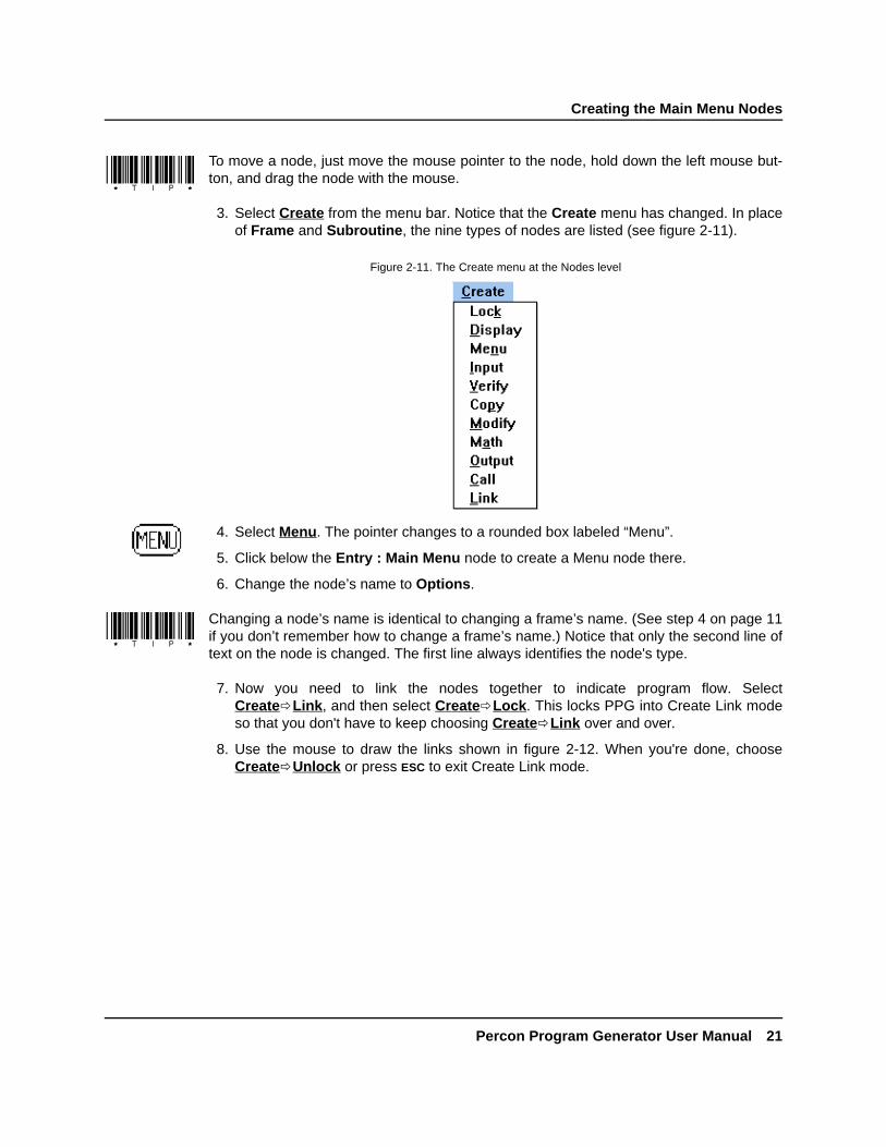
3. Select Create from the menu bar. Notice that the Create menu has changed. In placeof Frame and Subroutine, the nine types of nodes are listed (see figure 2-11).
4. Select Menu. The pointer changes to a rounded box labeled “Menu”.
5. Click below the Entry : Main Menu node to create a Menu node there.
6. Change the node’s name to Options.
Changing a node’s name is identical to changing a frame’s name. (See step 4 on page 11if you don’t remember how to change a frame’s name.) Notice that only the second line oftext on the node is changed. The first line always identifies the node's type.
7. Now you need to link the nodes together to indicate program flow. SelectCreateðLink, and then select CreateðLock. This locks PPG into Create Link modeso that you don't have to keep choosing CreateðLink over and over.
8. Use the mouse to draw the links shown in figure 2-12. When you're done, chooseCreateðUnlock or press ESC to exit Create Link mode.
Figure 2-11. The Create menu at the Nodes level

Chapter 2: Tutorial
22 Percon Program Generator User Manual
DRAFT—12/16/96 1:57pmD:\DOCS\PPG\CH2.FMD
9. Select the Menu : Options node to bring up the dialog box for it. The dialog boxincludes a text-entry area that is 16 characters wide and 4 lines deep, exactly the sizeof the portable’s screen (see figure 2-13).
10. On the first line, type ---Main Menu---.
11. Press ENTER twice to jump to the third line, and type Collect Data.
12. Press ENTER again and type Upload Data on the last line, as shown in figure 2-13.
To the left of the text-entry area are check boxes for function keys used to selectoptions presented on the portable’s screen. The menu options you've created arelined up with function keys F3 and F4 on the PocketReader. To initiate proper actionsfor these keys, you need to specify which node to progress to for each.
Figure 2-12. The completed Main Menu nodes
Figure 2-13. The Menu : Options dialog box

Saving Your Program
Percon Program Generator User Manual 23
DRAFT—12/16/96 1:57pmD:\DOCS\PPG\CH2.FMD
13. Select the F3 check box. A radio button appears next to the check box to show that thisis the active control. Click on the down-arrow button next to the input box at the bot-tom of the dialog box. A drop-down list appears, listing each node that this one islinked to (see figure 2-14).
14. Select Frame Collect Data so that when the user presses F3, the program willprogress to the Collect Data frame.
15. Select the F4 check box. A new selected radio button appears. Click on the down-arrow button next to the nodes input box, and select Frame Upload Data from thedisplayed list. This moves the program to the Upload Data frame when the userpresses F4.
16. Select Accept to exit the dialog box, and select an entry or exit node to return to theFrames level of the program.
Saving Your Program
Even though the program's not complete, it's a good idea to save it periodically as youbuild it, for safety's sake. Select FileðSave to save the program in a file. Entertutorial in the File Name input box of the displayed dialog box, and select OK. PPGwill add the extension .SCR automatically.
You have now completed the nodes of the Main Menu frame. These nodes display two op-tions on the portable’s screen and allow the user to indicate a choice by pressing F3 or F4.The program then checks to see which function key was pressed and passes control to ei-ther the Collect Data or Upload Data frame accordingly.
Figure 2-14. The drop-down list for Menu : Options

Chapter 2: Tutorial
24 Percon Program Generator User Manual
DRAFT—12/16/96 1:57pmD:\DOCS\PPG\CH2.FMD
Creating and Setting Up the Collect Data Nodes
The Collect Data frame allows the user to scan bar codes and enter data through the keysof the portable. That data is temporarily stored in a register and then copied into a file,which can be uploaded later to a PC.
You'll set up data-collection nodes to do the following:
• Display a message on the portable’s screen telling the user that the portable is ready toaccept data.
• Allow data input from the wand (scanner) or the portable’s keys, specify how to handleeach type of input, and name a register in which to store the data temporarily.
• Verify that the user input is valid and, if it is not, display an error message and sound abeep.
• Copy the data from the temporary register to a data file and redisplay the initial messageasking for input.
In addition, you’ll create an option that will allow the user to return to the Main Menu bypressing a function key.
Create nodes for the Collect Data frame by completing the following steps:
1. If you're returning from a break after exiting PPG, double-click on the PPG icon in thePercon PPG31 program group. Then choose FileðOpen and select tuto-rial.scr from the file list. Select OK to load the file into the PPG window.
2. At the Frames level, select the Collect Data frame to access its Nodes level. Becausethis frame has two links (one to it and one from it), there are two nodes initially cre-ated: Entry : Collect Data and Exit To : Main Menu. Reposition these nodes so thatthe Entry node is in the upper left corner and the Exit node is at the bottom right.
If you click twice on either of these nodes, you'll end up back in the Frames level.
Want a Break? If you're ready for a break, you can easily stop here. Since you justsaved your program in a file, you won't lose any work if you exit PPGor turn off your computer.

Creating and Setting Up the Collect Data Nodes
Percon Program Generator User Manual 25
DRAFT—12/16/96 1:57pmD:\DOCS\PPG\CH2.FMD
3. Create all the nodes shown in figure 2-15, using commands on the Create menu.Each node's type is indicated by the first line of text in the node. Rename each nodeaccording to the second line of text. Link the nodes together as shown.
When linking the Verify : Input node, create the link to the Output : Error Beep node first.This actually creates two links (a requirement for verify nodes), one on top of the other. Ifyou try to create another link, the program won’t let you. Instead, place the mouse pointerover the arrow of the top link, press and hold down the left mouse button, and drag thelink to the Copy To : File node. Then release the mouse button and click it once to set thelink. The underlying link (from the Verify node to the Output node) stays in place.
Figure 2-15. The Collect Data nodes

Chapter 2: Tutorial
26 Percon Program Generator User Manual
DRAFT—12/16/96 1:57pmD:\DOCS\PPG\CH2.FMD
THE DISPLAY : ENTER ITEM NODE You need to set up this node to display “Enter Item:”on the first line of the portable’s screen and have the fourth line of the screen tell the userto press F4 to return to the Main Menu. Complete the following steps to set up the node:
1. Select the Display : Enter Item node to open the node’s dialog box (see figure 2-16).
2. Type Enter Item: on the first line of the text entry area.
3. Press ENTER three times, and type Menu on the fourth line.
4. Select Accept to save your settings.
THE INPUT : ITEM NODE Complete the following steps to set up this node:
1. Select the Input : Item node to display its dialog box (see figure 2-17).
Figure 2-16. The Display : Enter Item dialog box
Figure 2-17. The Input : Item dialog box

The Input : Item Node
Percon Program Generator User Manual 27
DRAFT—12/16/96 1:57pmD:\DOCS\PPG\CH2.FMD
2. The Input From check boxes let you indicate which sources of input you want the por-table to accept. Select the Scanner, Data Key, and 'Fn' Key check boxes. This willallow the user to input data by scanning or pressing keys.
A radio button appears next to each selected check box. These buttons let you specifya different Link To setting for each type of input allowed. In this case, you want wand(scanner) and data-key input to link to the Verify : Input node and function key inputto return the user to the Main Menu.
3. Select the radio button next to the 'Fn' Key option, and then click on the down-arrowbutton to the right of the Link To input box. A list of the nodes or frames that the Inputnode is linked to is displayed.
4. Select Frame Main Menu. This tells the program to return to the Main Menu when-ever the user presses a function key.
5. If you created the link to the Verify node first, all input types will link to that node bydefault, and you won't need to adjust the settings. Otherwise, set the other selectedinput types to Verify Input.
6. You want the user to see the data as it is being entered, so select the Echo to Displaycheck box. This displays the characters being entered with the data keys on the por-table’s screen. To specify the exact position of the display on the screen, click on theright-arrow button to the right of the check box. The Input Echo : Item dialog boxappears (see figure 2-18).
The Echo to Display option displays keyed-in characters only until the user presses theENTER key. Once the data is entered (or scanned), the program moves on through the nextnodes and redisplays the menu text, overwriting the echoed characters. To avoid this, youwould need to add Output nodes to reposition the cursor and display the echoed charac-ters on a different line. This is demonstrated later in the tutorial.
7. Select the Specify Position check box. Input boxes appear, allowing you to indicatethe exact row and column you want the echoed data to begin on. Position it on thesecond row and first column. Columns and rows are numbered starting with 0 insteadof 1; so enter 1 in the Row box to indicate the second row and 0 in the Col box to indi-cate the first column (see figure 2-19).
Figure 2-18. The Input Echo : Item dialog box

Chapter 2: Tutorial
28 Percon Program Generator User Manual
DRAFT—12/16/96 1:57pmD:\DOCS\PPG\CH2.FMD
n
8. Select Accept. Now you need to create a special register for the input data to keep itseparate from other data.
A register is a temporary holding place for data. Unless you specify otherwise, the pro-gram stores input data in a register named Default Register. You can use numerous regis-ters in a program, storing different types of information in different registers.
9. Click on the down-arrow button to the right of the Register input box in the subdialogbox below the main one. A list of the program's existing registers appears, as shown infigure 2-20.
To delete an unwanted register, select it in the list, and then press DELETE.
Figure 2-19. The Input Echo dialog box
Figure 2-20. The list of the program’s registers

The Verify : Input Node
Percon Program Generator User Manual 29
DRAFT—12/16/96 1:57pmD:\DOCS\PPG\CH2.FMD
10. Type Inventory in the input box to create a new register named Inventory. TheReplace option (selected by default) clears existing data from the register before stor-ing newly input data.
11. Select Accept to save your settings and exit the dialog box.
THE VERIFY : INPUT NODE The Verify : Input node ensures that the data entered is nu-meric. If the data isn’t numeric, the node passes control to the Output and Display nodes,which sound a beep and display an error message. Complete the following steps to set upthis node:
1. Select the Verify : Input node to display its dialog box (see figure 2-21).
2. Select the Numeric radio button under the Type option. Because you don't want toverify any specific number, leave the Match option set to None.
3. The Link On option is automatically set according to the links you create. The top linkalways defines the Pass setting. It should be set to go to the Copy : To File node ifthe data is numeric (Pass) and the Output : Error Beep node if it's not (Fail). If thesesettings are reversed, click on the switch button next to the option to switch them.
4. You also need to tell the program what register to verify. Click on the down-arrow but-ton next to the Register input box, and choose Inventory from the list. (You may needto scroll down through the list to find it.)
5. Select Accept to save your settings and exit the dialog box.
Figure 2-21. The Verify : Input dialog box

Chapter 2: Tutorial
30 Percon Program Generator User Manual
DRAFT—12/16/96 1:57pmD:\DOCS\PPG\CH2.FMD
THE OUTPUT : ERROR BEEP NODE Now you need to set the Output : Error Beepnode to sound a beep. Complete the following steps:
1. Select the Output : Error Beep node to display its dialog box (see figure 2-22).
2. Select System as the Output To setting and Constant as the Source setting. In thenew input box that appears, enter the characters .+ (period and plus). This is a spe-cial code telling the program to sound a high beep. (You can enter .– to sound a lowbeep.) Because the system already beeps once when a code is scanned, this causesit to beep twice on an error.
3. Select Accept to save your settings and exit the dialog box.
THE DISPLAY : ERROR TEXT NODE You can have a special message appear when theerror beep is sounded. Select the Display : Error Text node, enter the text shown in figure2-23, and select Accept.
Figure 2-22. The Output : Error Beep dialog box
Figure 2-23. The Display : Error Text dialog box
The Copy : To File Node
Percon Program Generator User Manual 31
DRAFT—12/16/96 1:57pmD:\DOCS\PPG\CH2.FMD
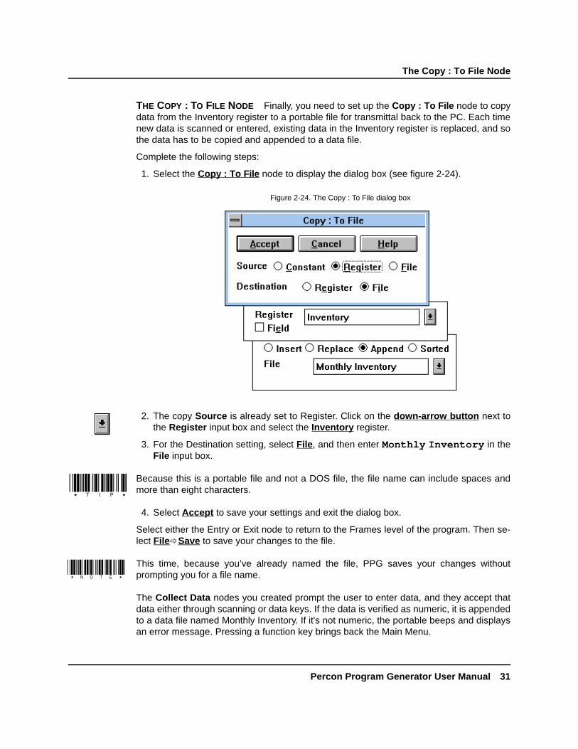
THE COPY : TO FILE NODE Finally, you need to set up the Copy : To File node to copydata from the Inventory register to a portable file for transmittal back to the PC. Each timenew data is scanned or entered, existing data in the Inventory register is replaced, and sothe data has to be copied and appended to a data file.
Complete the following steps:
1. Select the Copy : To File node to display the dialog box (see figure 2-24).
2. The copy Source is already set to Register. Click on the down-arrow button next tothe Register input box and select the Inventory register.
3. For the Destination setting, select File, and then enter Monthly Inventory in theFile input box.
Because this is a portable file and not a DOS file, the file name can include spaces andmore than eight characters.
4. Select Accept to save your settings and exit the dialog box.
Select either the Entry or Exit node to return to the Frames level of the program. Then se-lect FileðSave to save your changes to the file.
This time, because you’ve already named the file, PPG saves your changes withoutprompting you for a file name.
The Collect Data nodes you created prompt the user to enter data, and they accept thatdata either through scanning or data keys. If the data is verified as numeric, it is appendedto a data file named Monthly Inventory. If it's not numeric, the portable beeps and displaysan error message. Pressing a function key brings back the Main Menu.
Figure 2-24. The Copy : To File dialog box

Chapter 2: Tutorial
32 Percon Program Generator User Manual
DRAFT—12/16/96 1:57pmD:\DOCS\PPG\CH2.FMD
Creating and Setting Up the Upload Data Nodes
The last frame, Upload Data, allows the user to copy collected data from the portable’s fileto a file on the PC. You will set up nodes that do the following:
• Display a menu asking if the user wants to upload data.
• If the response is Yes (F3), send data over the serial connector to the PC. If theresponse is No (F4), exit to the Main Menu.
• If the output is successful, display a message saying so for 45 seconds (or until the userpresses a key), and then clear the portable’s file and return to the Main Menu. If the out-put is unsuccessful, beep and display an error message, and then redisplay the prompt.
Create nodes for the Upload Data frame by completing the following steps:
1. Select the Upload Data frame to move into its Nodes level.
2. Reposition the Entry and Exit nodes as shown in the completed flow chart in figure2-25.
3. Create and name the new nodes shown in figure 2-25, and add the links as shown.
Figure 2-25. The Upload Data nodes

The Menu : Confirmation Node
Percon Program Generator User Manual 33
DRAFT—12/16/96 1:57pmD:\DOCS\PPG\CH2.FMD
When creating the links from the Output : to PC node, create the link to the Output :Error Beep node first. Two links are automatically created, one on top of the other. Placethe mouse pointer over the arrow of the top link, press and hold down the left mouse but-ton, and drag the link to the Display : Successful node. The underlying link stays inplace.
THE MENU : CONFIRMATION NODE Complete the following steps to set up this node:
1. Select the Menu : Confirmation node to open its dialog box, and enter the text shownin figure 2-26. (Be sure to leave the second line blank.)
2. Select the F3 check box. Then click on the down-arrow button next to the input box,and select Output to PC from the drop-down list. This will make the portable beginoutputting data when the user presses F3.
3. Select the F4 check box, and select Frame Main Menu from the drop-down list. Thiswill redisplay the Main Menu when the user presses F4.
4. Select Accept to save your settings and exit the dialog box.
Figure 2-26. The Menu : Confirmation dialog box

Chapter 2: Tutorial
34 Percon Program Generator User Manual
DRAFT—12/16/96 1:57pmD:\DOCS\PPG\CH2.FMD
THE OUTPUT : TO PC NODE Complete the following steps to set up this node:
1. Select the Output : to PC node to open its dialog box (see figure 2-27).
2. Select the Serial setting for Output To. This will send the output to the serial port ofthe portable, which should be connected to the serial port of the PC.
3. Make sure the Link On Success option is set to Display Successful and Failure isset to Output Error Beep.
4. For the Source option, select File. Then click on the down-arrow button next to theFile input box, and select Monthly Inventory from the drop-down list.
5. Select Accept to save your settings and exit the dialog box.
THE OUTPUT : ERROR BEEP NODE Complete the following steps to set up this node:
1. Select the Output : Error Beep node to open its dialog box.
2. Select System as the Output To setting and Constant as the Source setting.
3. Enter .+ in the Source input box.
4. Select Accept to save your settings and exit the dialog box.
Figure 2-27. The Output : to PC dialog box

The Menu : Error Text Node
Percon Program Generator User Manual 35
DRAFT—12/16/96 1:57pmD:\DOCS\PPG\CH2.FMD
THE MENU : ERROR TEXT NODE Complete the following steps to set up this node:
1. Select the Menu : Error Text node and enter the text shown in figure 2-28.
2. Select the F3 check box and choose Output to PC from the drop-down list. Select F4and choose Frame Main Menu. This will try outputting again if the user presses F3and return to the Main Menu if the user presses F4.
3. Select Accept to save your settings and exit the dialog box.
THE DISPLAY : SUCCESSFUL NODE Complete the following steps to set up this node:
1. Select the Display : Successful node to open its dialog box.
2. Enter the text shown in figure 2-29.
A Menu node is not necessary here, because only one option is given, and it is executed ifany function key is pressed, not just F4. The Input node that follows this one will see tothat.
3. Select Accept to save your settings and exit the dialog box.
Figure 2-28. New text for the Menu : Error Text node
Figure 2-29. Display text for successful upload

Chapter 2: Tutorial
36 Percon Program Generator User Manual
DRAFT—12/16/96 1:57pmD:\DOCS\PPG\CH2.FMD
THE INPUT : TIMEOUT DISPLAY NODE Complete the following steps to set up this node:
1. Select the Input : Timeout Display node to open its dialog box.
2. Select the Scanner check box to turn it off. (There should be no x in the box.)
3. Select the 'Fn' Key and TimeOut check boxes.
4. Enter 45 in the Seconds input box that appears next to TimeOut. This instructs theprogram to return to the Main Menu if the user presses a function key or if 45 secondspass with no input.
5. Select Accept to save your settings and exit the dialog box.
THE MODIFY : ERASE FILE NODE Once you've uploaded data from your portable file,you'll probably want to erase its contents. Otherwise, further data you collect will be ap-pended to the data you just uploaded, and your data file will quickly grow out of control.Complete the following steps:
1. Select the Modify : Erase File node to open its dialog box.
2. Select the Delete radio button.
3. Select File as the Data setting, and choose Monthly Inventory from the drop-downfile list (see figure 2-30).
4. Select Accept to save your settings and exit the dialog box.
The nodes for uploading data are now complete. Select either the Entry or Exit node to re-turn to the Frames level. Then select FileðSave to save your changes to the file.
Figure 2-30. The Modify : Erase File dialog box

Emulating the Program
Percon Program Generator User Manual 37
DRAFT—12/16/96 1:57pmD:\DOCS\PPG\CH2.FMD
The nodes that you created for the Upload Data frame ask the user for confirmation of theupload task. If the user answers Yes, it outputs the data file over the serial port. If the up-load is successful, a message is displayed, the portable’s file is cleared, and the MainMenu returns. If the upload is unsuccessful, the program beeps, displays an error mes-sage, and gives the user the option of trying again.
Your portable program should now be complete.
Emulating the ProgramThe Emulation window lets you test your program before you load it into the portable. Itruns through your program step by step, displaying exactly what would appear on yourportable screen and responding to your input just as the portable would. You can see if theprogram will work as you expected.
Use the Emulation window now to test your program. Complete the following steps:
1. If you're returning from a break and had exited PPG, double-click on the PPG icon inthe Windows Percon PPG31 program group.
2. Select FileðOpen, choose tutorial.scr from the file list, and select OK to loadthe file into the PPG window.
3. Select ViewðEmulation to open up the Emulation window. By default, the window ismodeled after the face of a Percon PocketReader™ portable, with the display screenon the right and keys below and to the left (see figure 2-31). If you choose PT 2000from the Options menu, however, the window changes to look like a PT 2000™portable.
In either case, the name of the emulated program's current frame and node are dis-played in the title bar. Commands in the menu bar let you run the program and setemulation options. An input box displays data you enter, and a check box lets youenable or disable the timeout setting, if any. When timeout is enabled, the timeoutvalue is counted down in the adjacent input box.
Want a Break? If you're ready for a break, you can easily stop here. Since you savedyour file, so you won't lose any work if you exit PPG or turn off yourcomputer.

Chapter 2: Tutorial
38 Percon Program Generator User Manual
DRAFT—12/16/96 1:57pmD:\DOCS\PPG\CH2.FMD
4. Select OptionsðWatch from the menu to open the PPG Watch window. This windowdisplays the contents of given registers while the program is running. You'll use it toview the contents of the Inventory register as you input data.
5. Select SetUp from the PPG Watch menu bar. The Setup Watch dialog box appears,listing all named registers for the program (see figure 2-32).
6. Select Inventory from the Registers list and click on the Add button to move it to theWatch list below it. Then select Default Register from the Watch list and selectRemove to delete it from the list. Select Ok.
7. Select Run from the Emulation window's menu bar to start the program. The por-table’s screen area displays the Main Menu you set up, and the menu bar changes toa single command (see figure 2-33). In addition, the function keys (F1–F4) are nolonger dimmed, meaning that they are now available for use.
Figure 2-31. The Emulation window
Figure 2-32. The Setup Watch dialog box

Emulating the Program
Percon Program Generator User Manual 39
DRAFT—12/16/96 1:57pmD:\DOCS\PPG\CH2.FMD
8. Click on the F3 button in the window to choose the Collect Data option. Text from theDisplay : Enter Item node appears in the screen area, prompting you to input data,and the menu bar changes to show the following commands: Wand, Serial, Timeout,and Stop (see figure 2-34).
The first three commands let you simulate a specific type of input; only Wand inputcan be selected at this point. The Stop command halts program emulation.
9. Enter 123456 in the input box by clicking on the data keys on the screen.
10. Select the Wand menu option to emulate scanning. The number is stored in the Inven-tory register (as you can see by checking the PPG Watch window), and the input boxis cleared for further input.
11. Enter 98765 in the input box and click on the ENTER button in the window to emulatekeying in a number. This number replaces the previous one in the Inventory register,and the input box is cleared.
Figure 2-33. The Main Menu displayed in the Emulation window
Figure 2-34. The Emulation window prompting for input

Chapter 2: Tutorial
40 Percon Program Generator User Manual
DRAFT—12/16/96 1:57pmD:\DOCS\PPG\CH2.FMD
12. Now enter Q1234 in the input box and select the Wand option. The emulator beeps,the screen area shows the “Invalid Entry. Try Again” message, and the input box iscleared. The invalid number is stored in the register (as shown in the PPG Watch win-dow), but it is not copied to the file.
To enter a letter, click on the Shift button in the window until the letter you want appears onits designated key, and then click on that key. For example, to enter Q, click on the Shiftbutton twice and then click on the PQR key, in which the letter Q should be visible.
13. Reenter the number, this time without the letter (1234), and select Wand.
14. Click on the F4 button in the window to return to the Main Menu.
15. Click on the F4 button again, this time to choose the Upload Data option. The screenarea displays “Ready to Upload?” and offers Yes and No options.
16. Click on the F3 button for Yes. The emulator pretends to write the data to a file (it neveractually alters any files) and displays the “Upload complete” message.
17. Click on the F4 button to return to the program's Main Menu.
18. Select Stop, and then select OptionsðWatch again to close the PPG Watch window.
19. Double-click on the Emulation window's Control-menu box to close it and return toPPG.
You can use other Emulation commands to run only the next step of a program, set break-points at which you want to pause the program, and display a “Trace” window that docu-ments every action taken. See chapter 3 for details.
If you encountered any problems or unexpected results as you ran the program in theEmulation window, you should recheck your program against the steps in the “BuildingYour Own Portable Program” section.
Loading and Using the ProgramNow that your program is tested and complete, it's time to load it into the portable and try itout. Complete the following steps:
1. If the cable is not already connected to your portable and the PC, connect it now (asdescribed on page 15).
2. Turn the portable on.
3. In the PPG window, select FileðDownload Program. (If you are prompted to saveyour changes, answer Yes.)

Loading and Using the Program
Percon Program Generator User Manual 41
DRAFT—12/16/96 1:57pmD:\DOCS\PPG\CH2.FMD
The Percon Portable Compiler window appears while PPG compiles the program.When compiling is complete, the Percon Portable Programmer window displays themessage “Initiating Download.” If connection is successful, the program is loaded intothe portable. When downloading is complete, the message “Portable successfully pro-grammed” appears in the Percon Portable Programmer window, and the program'sMain Menu is displayed on the portable’s screen.
4. Double-click on the Percon Portable Programmer window's Control-menu box orselect FileðExit to close the window. (If downloading was unsuccessful, chooseAbort from the menu bar first.)
5. Double-click on the Control-menu box in the Compiler window to close it.
6. Disconnect the portable from the cable, and press the F3 key to begin collecting data.
7. Scan the following bar codes at least once. Each time a code is scanned correctly, youshould hear a single beep. (You won't see the scanned codes on the portable’sscreen, because they are overwritten by the redisplayed menu once the data is input.)When you scan the last code, which contains an alphabetic character, you'll hear adouble beep, indicating an error.
If You Have Problems
If a few seconds pass with no messages, PPG was unable to makethe connection with the portable. Select the Comm2 command on thePercon Portable Programmer menu bar to select a different serialport, and then select the Download Program command to try again.Also, make sure that the cable is firmly connected at both ends. Youmight try resetting the portable by holding down Shift+Enter whileyou reload the battery.
If you loaded a different program into your portable since downloadingthe sample program earlier, the portable may not be set to allow serialinput, or the serial parameters may not be set correctly. In this case,scan the following bar code or select options in the portable to pre-pare it for downloading.
*/.*

Chapter 2: Tutorial
42 Percon Program Generator User Manual
DRAFT—12/16/96 1:57pmD:\DOCS\PPG\CH2.FMD
8. Now enter the following codes using the portable’s data keys. The portable will beepeach time you press a key. Press ENTER after each complete number.
12345678909876554321
9. Press the F4 key to return to the program's Main Menu.
Uploading Data from the PortableNow use the PTFER program to upload the data you collected to your computer. Completethe following steps:
1. Click on the Minimize button in the PPG window to temporarily put it out of sight.
2. Back in the Windows Program Manager, double-click on the PTFER icon in the PerconPPG31 program group to display the PTFER window.
3. If your serial port is not COM2, select OptionsðSettings from the menu, select thecorrect COM port, and select Ok.
4. Select OptionsðConnect. A message appears in the window, saying the connectionwas successful.
5. Select FileðReceive. In the Receive File dialog box, type the file name invntoryand select OK. The file name appears in the PTFER window's title bar, with the .TXT
extension added automatically.
6. Reconnect the cable to the portable, and press the F4 key (for Upload Data) on theportable.
7. Press the F3 key (for Yes) to confirm uploading.
The data that you scanned and entered is immediately transferred from the portable’sfile called “Monthly Inventory” to a DOS file on your PC called INVNTORY.TXT.
If this doesn’t happen, check your connections and COM port setting, and try again. Theportable defaults to 9600 baud, no parity, 8 data bits, and 1 stop bit. To reset the portableto these defaults, scan the following:
*$+$-C8EE*8. Double-click on the PTFER window's Control-menu box or choose FileðExit to
close the window.
For complete information about PTFER (including running it with command line options),see “Using PTFER,” beginning on page 94.

Creating and Using Templates
Percon Program Generator User Manual 43
DRAFT—12/16/96 1:57pmD:\DOCS\PPG\CH2.FMD
Creating and Using TemplatesThe programs you've worked with so far handle singular information: You scan or enterone code at a time, and the data is stored one entry per line. But suppose you wanted tocollect sets of different types of data. If you were taking inventory, for example, rather thanscanning each item in a group of identical products, you might want to scan only one ofthem and then use the data keys to record the number of items in the group.
You could add another Input node to the Collect Data frame of your program to store thetypes of data in different registers, but the data file you would end up with would have codenumbers and quantity numbers on alternate lines, as in the following:
3849293593858341298484958
This arrangement of data would be difficult for an inventory or database program to inter-pret. Most programs expect to see related values on the same line, as in the following:
3849293, 59385834, 129848495, 8
In this arrangement, each line is referred to as a record, and each item on the line is calleda field. The database program can be set up to treat the first field as an inventory code andthe second as a quantity value.
The way you tell a portable program to arrange data as fields in records is with a template.A template defines the structure used to access data. Most often, a template is used tocombine values in two different registers as fields in a single register. The fields are eitherset to a fixed length (so that they appear in columns in the data file), or they are allowed avariable length with a separator (such as a comma) separating them. However, you canalso use a template to break apart data stored in a register into separate fields.
You will incorporate a template into the TUTORIAL program to collect and store quantityvalues along with each item number. To do this, you'll add the following new nodes to theexisting TUTORIAL program:
• A new Display node that will prompt the user to enter a quantity value after an item num-ber is entered
• A new Input node that will use a template to store the quantity value in a register field
• Two Output nodes that will display the last-entered item and quantity values as a pair
You'll also alter the existing Input node to use a template.

Chapter 2: Tutorial
44 Percon Program Generator User Manual
DRAFT—12/16/96 1:57pmD:\DOCS\PPG\CH2.FMD
Creating the New Nodes
Create the new nodes by completing the following steps:
1. Double-click on the PPG icon at the bottom of the Windows desktop to reopen PPG.
2. The TUTORIAL program file (TUTORIAL.SCR) should still be loaded, but if it isn’t, useFileðOpen to load it. (Your screen will have links not shown in the figure.)
3. At the Frames level, select the Collect Data frame, and reposition the nodes as shownin figure 2-35.
4. Delete the link from the Verify node to the Copy node.
To delete a link, use the mouse to drag its arrowhead away from a node, and double-clickthe left mouse button.
5. Adjust the links from the Copy node to the Display node and from the Input node to theExit node so that they are no longer jointed.
Figure 2-35. The repositioned Collect Data nodes

Creating the New Nodes
Percon Program Generator User Manual 45
DRAFT—12/16/96 1:57pmD:\DOCS\PPG\CH2.FMD
You can either delete existing links and create new ones or drag the joints of the links untilthey line up.
6. Add the new nodes and links shown in figure 2-36, and rename the nodes as shown.
Select CreateðLock and then click the right mouse button to cycle through the itemsyou can create.
7. Select the new Display node (Display : How Many?), and enter How Many? on thefirst line and Menu on the fourth. Then select Accept.
8. Skip over the two Output nodes for now, and select the new Input node (Input : Quan-tity). Select the Data Key and 'Fn' Key check boxes, and select the Scanner option toturn it off. Link the 'Fn' Key setting to Frame Main Menu and the Data Key setting toCopy to File.
9. Select the Echo to Display check box and click on the right-arrow button next to it.Select the Specify Position option and enter 1 in the Row input box and 0 in the Colbox. Then select Accept.
Figure 2-36. The new Collect Data nodes

Chapter 2: Tutorial
46 Percon Program Generator User Manual
DRAFT—12/16/96 1:57pmD:\DOCS\PPG\CH2.FMD
Creating the Fields
Create the template fields by completing the following steps:
1. In the subdialog box at the bottom of the Input : Quantity dialog box, click on thedown-arrow button next to the Register input box, and choose Inventory from thedrop-down list. (Do not select Accept yet.)
Inventory is the same register used to store the item number. To keep one value frombeing overwritten by the other, you will create a template that divides the register into twofields: one for the quantity and one for the item number.
2. To create the template name, select the Field radio button in the subdialog box. Twonew input boxes appear: Template and Field. Click on the right-arrow button next tothe Template input box to display the Define Template dialog box (see figure 2-37).Type Combine in the Template input box for the new template’s name.
3. Now create the field names and define their lengths. Click on the right-arrow buttonnext to the Define Fields input box to display the Define Field dialog box (see figure2-38). You will define two fields for this template: Item and Quantity. Type Item in theField input box. Because you don't want to limit this field to any specific length, selectthe Variable radio button and enter a comma (,) in the Delimiter input box. This willseparate the two values with a comma. Then select Done.
Figure 2-37. The Define Template dialog box
Figure 2-38. The Define Field dialog box

Creating the Fields
Percon Program Generator User Manual 47
DRAFT—12/16/96 1:57pmD:\DOCS\PPG\CH2.FMD
4. Click on the right-arrow button next to the Define Fields input box again. This time,type Quantity in the Field input box, select Variable, and enter a space in theDelimiter box. Select Done.
5. Next, you will define the order of the fields in the template. Click on the down-arrowbutton next to the Define Fields input box to see your new fields included in the list ofpossible fields. Select Item from the list, and select the Add button to add it to the listin the Fields input box. Click on the down-arrow button again and select Quantity.Then select Add.
You may need to scroll through the list to find the fields you want.
6. Click on the down-arrow button next to the Fields input box to see both Item andQuantity listed as fields for the Combine template. Select Done. You can now use thetemplates and fields in the nodes.
7. In the subdialog box below the Input : Quantity dialog box, click on the down-arrowbutton next to the Template input box, and choose Combine. Set the Field input boxto Quantity. This tells the program to store the value input after the “How Many?”prompt in the Quantity field of the Inventory register. Select Accept.
8. Now you can specify storing the input item number in the Item field of the register.(The program will work correctly whether or not you perform this step.) Select theother Input node (Input : Item) and select the Field radio button in the Register sub-dialog box. Select Combine from the Template drop-down list, and then select Itemfrom the Field drop-down list. Select Accept.
9. The two new output registers make it possible to display the Item value without over-writing the “How Many?” prompt. Select the first one (Output : Position), and selectthe Constant radio button in the dialog box. Then enter the following in the input boxthat appears:
\x1B[2;0f
Enter the characters exactly as shown. (The eighth character is a zero, not the letter O.)
This character string is a special code recognized by PPG. It positions the cursor inthe first column of the third row. (Further output commands are described inchapter 3.) Be sure the Output to Display option is selected (it’s the default), andselect Accept.
10. Select the other Output node (Output : Register), select Inventory from the Registerdrop-down list, and select Accept. This displays the contents of the Inventory registerat the cursor position on the portable’s screen.
11. Select FileðSave to store the changes you've made.
12. Connect the portable to your PC as described earlier, and select FileðDownload.The new program is compiled and loaded into the portable. When it's done, you canexperiment with collecting data using the new program. Notice that after you enter theitem and quantity values, both entries are displayed together on the third line, sepa-rated by a comma.

Chapter 2: Tutorial
48 Percon Program Generator User Manual
DRAFT—12/16/96 1:57pmD:\DOCS\PPG\CH2.FMD
This is the end of the tutorial. What you've learned here should give you the understandingand background you need to develop your own portable programs. The next chapter willgive you all the specific information required. It covers every detail of each availableoption.
49
DRAFT—12/16/96 1:57pmD:\DOCS\PPG\CH3.FMD
Chapter 3
*USERS*GUIDE*USERS*GUIDE*USERS*GUIDE*USERS*GUIDE*USERS*GUIDE*USERS*GUIDE*USERS*GUIDEUser’s Guide
This chapter gives you details on every command and option available within PerconProgram Generator (PPG). The following subjects are covered:
• Using online help and working with a mouse
• Creating frames, subroutines, nodes, and links to build a program
• Making adjustments to a program flow chart
• Setting program options, such as the types of bar codes to be read
• Saving, opening, closing, and printing program flow chart files
• Using the Emulation window to debug a program flow chart
• Downloading a program into the portable
• Transferring data between the portable and the PC
• Using templates and files to organize and format collected data
Once you've read this chapter, you may want to return to it from time to time for informationabout procedures and options.
Using Online HelpWhile you're working in PPG, you can easily access online help for specific commands,procedures, or concepts. There are four ways you can get help:

Chapter 3: User’s Guide
50 Percon Program Generator User Manual
DRAFT—12/16/96 1:57pmD:\DOCS\PPG\CH3.FMD
• Press F1. The help screen that appears depends on where you are in the program andwhat you're doing. If a menu command is highlighted, the help screen describes thatcommand.
• Select the Help button. Most dialog boxes in PPG include a Help button. Select thisbutton to display help about the dialog box's options.
• Press SHIFT+F1. A question mark appears next to the mouse pointer. Use this pointer toclick on an area of the screen you want help on.
• Select a command from the Help menu. Commands in this menu take you to differentareas of the online help system. Contents displays the main help screen, which listsgeneral help topics. About PPG displays a Percon identification screen that shows theversion number of your program.
All online help screens are linked together via jumps, which are graphics or text that leadto a different help screen when selected. Text jumps are identified by a different color andan underline. When you point to a jump, the pointer changes to a hand shape, as shown infigure 3-1. Click the left mouse button while pointing to a jump to display complete informa-tion on the topic.
When you click on a jump that has a dashed underline, a pop-up window opens. To closea pop-up window, click a mouse button or press a key.
The PPG help window contains its own menu bar of commands. You can use them to loadanother help file, print help screens, copy a help screen to the Clipboard, insert a graphic,set bookmarks for saving your place, display help on using help, and keep the help windowfrom being covered by other windows.
The help window also includes a set of command buttons across the top. You can selectthese buttons to jump to the help contents screen, search for help on a given topic, jump tothe previously displayed screen, and display a history of displayed screens that you canjump back to.
For detailed instructions on using all of the online help commands and features, press F1from within the help window or select HelpðHow to Use Help from the help menu bar.
When you're done using help, select FileðExit or, if you think you will want to use helpagain, press ALT+TAB. The help window does not close then, but instead it moves behindthe PPG window. When you select help (or press ALT+TAB) again, the help window movesto the front.
Figure 3-1. The help pointer over a jump

Using the Mouse
Percon Program Generator User Manual 51
DRAFT—12/16/96 1:57pmD:\DOCS\PPG\CH3.FMD
Using the MouseLike most Windows applications, PPG makes extensive use of the mouse. Table 3-1shows standard mouse techniques that have special effects in PPG.
Depending on what you're doing with the mouse, the pointer changes to reflect the currentaction:
Table 3-1. Mouse Techniques
Mouse Action Effects
Left button,single click
• On an object, such as a menu command or frame, selects that object.
• In Create mode, creates the object specified by the cursor label at the cursor position.
• When creating a link, specifies the beginning or end of the link or a joint.
• With two or more overlapped links selected, selects the next link in the stack.
Left button,double click
• At the Frames level, enters the Nodes level for the selected frame.• On an Entry or Exit node, reverts to the Frames level.• On any other node, opens the node's dialog box.• While holding a link, deletes that link.
Left button,press and hold; drag
• On an object, moves the object with the pointer until the button is released.Not on an object, draws a rectangle on the screen. All objects within the rectangle are selected and can be moved or adjusted at once.
Right button,single click
• On a frame or node, opens the Name dialog box.• In Create mode, selects the next option on the Create menu.
Right button,double click
• Places PPG in Create mode.
If you're making a simple selection or dialog box entry, the pointer isthe standard arrowhead.
If you're creating an object, the pointer appears as a rounded box witha label that identifies the type of object you're creating.
When you're moving a frame, node, or link, the pointer changes to anopen hand.
When you press SHIFT+F1, a question mark is added to the standardpointer, which you can position on a part of the screen you want helpon. When you click the left mouse button, online help for that areaappears.

Chapter 3: User’s Guide
52 Percon Program Generator User Manual
DRAFT—12/16/96 1:57pmD:\DOCS\PPG\CH3.FMD
Generating a Portable ProgramThe first step in generating a portable program is figuring out what you want the programto do. Put yourself in the end user's shoes and walk through the steps of the imagined pro-gram. Consider each action involved.
• How will the user start? Do you want to identify the user first by asking for a password orID number? What about a log-on message?
• To offer a choice of actions, such as collecting and uploading data, you should probablyset up a Main Menu that can be accessed from different areas of the program. List in thismenu each general action the user might want to take. For example, in addition to col-lecting and uploading data, the user might want to erase a portable file or download afile from the PC. If an action will be taken only in a specific area of the program, however,you may not want it on the Main Menu. You can offer the option through another menulater. You may want to have the F8 key in the Main Menu bring up a sign-on displayshowing the name of your program and its version number or creation date.
• In your mind, move through the individual steps involved in each major action. For exam-ple, will the user be collecting different types of data at different times? If your inventoryis divided into categories, you might want the user to identify the category before collect-ing the data. This could be done with a “collection” submenu. For each action you wouldtake as a portable user, imagine the options you would expect to have and the mes-sages you would expect to appear on the screen.
• In what order will the actions be taken? Is there an obvious direction to the program? Forexample, a user would normally collect data and then upload it. This order should bereflected in the Main Menu and in the program flow.
• Are there steps that you might want to access from different areas of the program, suchas writing data to a file or displaying the date? If so, you can save time and program sizeby putting these steps into a subroutine that can be called from different areas of theprogram.
You may want to sketch out the program flow chart first with pencil and paper. When you'reready, go into PPG and choose FileðNew, if necessary, to clear the window. Then use theCreate menu commands (see pages 53–78) to build your program's flow chart.
Flow Chart Levels
There are two levels to every program flow chart: the Frames level and the Nodes level.You start in the Frames level, creating a frame for every major function of the program, andyou use links to hook the frames together in the way that the program flows. For eachframe in the chart, you also build a set of nodes that break down the frame's function intodetailed steps. To access the Nodes level of a frame, double-click on the frame with theleft mouse button, or select it and choose ViewðNodes. To return to the Frames level,select one of the Exit or Entry nodes or choose ViewðFrames.

Testing Your Program
Percon Program Generator User Manual 53
DRAFT—12/16/96 1:57pmD:\DOCS\PPG\CH3.FMD
Testing Your Program
Once you've completed the flow chart, use the ViewðEmulation command to load it intoan Emulation window for testing. To compile the program and load it into the portable, usethe FileðDownload Program command.
Before you download a program into the portable, make sure the OptionsðSet BarCodes command is set to decode the correct bar code symbologies (see “Specifying BarCode Type,” on page 83).
Creating FramesEach frame in a program flow chart represents a major function or option. Typically, a pro-gram's frames include a Main Menu frame and a frame for each option on the menu. Ar-rows, or links, connect the frames in a way that indicates program flow. Figure 3-2 showsthe frames of a sample program.
To create the frames of a program flow chart, complete the following steps:
Figure 3-2. The Frames level of a program

Chapter 3: User’s Guide
54 Percon Program Generator User Manual
DRAFT—12/16/96 1:57pmD:\DOCS\PPG\CH3.FMD
1. Select the CreateðFrame command from the menu. The pointer changes into arounded box labeled “FRAME”.
2. Position the box where you want to create the frame, and then click the left mouse but-ton. A frame box named “Frame1” appears, and the arrow pointer reappears. (Framesare automatically numbered in the sequence in which they are created. The nextframe you create will be named “Frame2”.)
To reposition the frame, move the pointer to it, hold down the left mouse button, and dragthe frame with the mouse. When the frame is positioned where you want it, release themouse button.
3. To give the frame a more useful name, click on it with the right mouse button orselect EditðRename from the menu to display the Frame Name dialog box (see fig-ure 3-2). Enter the text you want displayed in the frame box, and select Ok.
If you're creating several frames, you can lock PPG into Create mode so that you don'thave to choose CreateðFrame each time. Just select CreateðLock before selectingCreateðFrame. After you create a frame, the FRAME pointer will remain visible so thatyou can click again to create another frame. When you're done, choose CreateðUnlockor press ESC to exit Create mode and redisplay the arrow pointer, or click the right mousebutton twice to begin creating links.
Use the OptionsðSet Start command to specify which frame to start the program with(see “Setting a Starting Place,” on page 84).
Creating SubroutinesA subroutine contains nodes that execute program steps, very much like a frame. The dif-ference is that a subroutine sits off to the side of a frame flow chart instead of being linkedin with other objects. It contains functions that can be referenced within any of the pro-gram’s frames.
Figure 3-3. The Frame Name dialog box

Creating Subroutines
Percon Program Generator User Manual 55
DRAFT—12/16/96 1:57pmD:\DOCS\PPG\CH3.FMD
Subroutines are handy for when your program uses the same sequence of nodes in sev-eral frames. Rather than repeating the nodes for each frame, you can put them in a sub-routine on the Frames level and then use a Call node to reference the subroutine (see“Call Nodes,” on page 58). Figure 3-4 shows the Frames level of a program that containstwo subroutines: one for storing data collected in a file and one for displaying the date. Callnodes within the two program frames jump to the subroutines as needed.
Creating subroutines is the same as creating frames. Complete the following steps:
1. Select the CreateðSubroutine command from the menu. The pointer changes into arounded box labeled “SUB”.
2. Position the box where you want to create the subroutine, and then click the leftmouse button. A frame box named “Subroutine 1” appears, and the arrow pointerreappears. (Subroutines are automatically numbered in the same sequence asframes; if you create three frames and then a subroutine, for example, the subroutinewill be numbered 4.)
Since subroutines aren’t linked to other objects, their locations are unimportant. Normally,they are placed off to the side somewhere. To reposition a subroutine, drag it with themouse.
Figure 3-4. Subroutines in a PPG program

Chapter 3: User’s Guide
56 Percon Program Generator User Manual
DRAFT—12/16/96 1:57pmD:\DOCS\PPG\CH3.FMD
3. To rename the subroutine, click on it with the right mouse button or selectEditðRename from the menu to display the Frame Name dialog box. Enter the textyou want displayed in the subroutine box, and select Ok.
If you're creating several subroutines, you can lock PPG into Create mode so that youdon't have to choose CreateðSubroutine each time. Just select CreateðLock beforeselecting CreateðSubroutine. After you create a subroutine, the SUB pointer will remainvisible so that you can click again to create another subroutine. When you're done, chooseCreateðUnlock or press ESC to exit Create mode and redisplay the arrow pointer.
To reference a subroutine from within a frame, use a Call node (see “Call Nodes,” on page58). When the subroutine has been executed, control continues with the next node afterthe Call node.
Creating and Using LinksLinks are arrows that connect two frames or nodes, directing the program to the next step.A link pointing to a frame or node shows how it is accessed. A link pointing away from aframe or node shows where the program goes next.
Creating Links
To create a link, complete the following steps:
1. Select CreateðLink from the menu. The pointer changes into a rounded box labeled“LINK”.
2. Move the box to the frame or node you want to draw the link from, and click the leftmouse button.
The link will be drawn using the middle of each object as an axis, regardless of the exactposition of the pointer.
3. Move the box to the object you want the link to connect to, and click the left mousebutton again to draw the link.
To draw a jointed link (a link with one or more bends), click the mouse with the pointer onthe frame, move the LINK pointer to where you want the first joint to be, click the mouseagain, and draw the next leg of the link. You can create up to seven joints. Click inside aframe or node to complete the link.
When creating several links, you can lock PPG into Create mode so that you don't have tochoose CreateðLink each time. Just select CreateðLock before selecting CreateðLink. After you create a link, the LINK pointer will remain visible so that you can click againto begin creating another link. When you're done, select CreateðUnlock or press ESC toexit Create mode and redisplay the arrow pointer.

Adjusting Links
Percon Program Generator User Manual 57
DRAFT—12/16/96 1:57pmD:\DOCS\PPG\CH3.FMD
Adjusting Links
To adjust an existing link, move the arrow pointer to the link's arrowhead or joint, and holddown the left mouse button. Drag the joint or arrowhead to a new position, and then re-lease the mouse button.
If two or more links overlap, you can select them separately by moving the arrow pointer toa joint or arrowhead and holding down the left mouse button. The selected link appearsdashed. To select the next link in the stack, press and hold down the left button again.
Deleting Links
To delete an existing link, drag its arrowhead to an area away from any frames or nodes,and then double-click the left mouse button.
To delete a single link in an overlapping stack, click the left mouse button on the stack untilthe link you want to delete is selected (shown as a dashed line). Then drag its arrowheadto an empty area, and double-click the left mouse button.
Creating and Using NodesEach frame of a program flow chart contains its own set of nodes, which create, in effect, asublevel flow chart. Every frame is assigned at least one node automatically: an Entrynode, which shows the name of the frame. If the frame contains links to other frames, anExit node for each link is also created automatically. You add and link your own nodes todefine details for the frame.
To go into the Nodes level of a frame, just double-click on it. You can also move to it withthe mouse or the TAB key and then either select ViewðNodes from the menu or press theSPACEBAR. When you're in the Nodes level, the Create menu lists each type of node avail-able (see figure 3-5).
Figure 3-5. The Create menu in the Nodes level

Chapter 3: User’s Guide
58 Percon Program Generator User Manual
DRAFT—12/16/96 1:57pmD:\DOCS\PPG\CH3.FMD
To create a node, complete the following steps:
1. Select the type of node you want to create from the Create menu. The pointerchanges into a rounded rectangle labeled with the name of that node. (For example, ifyou select CreateðCopy, the pointer will look like the one shown at the left.)
2. Position the rectangle pointer where you want to create the node, and then click theleft mouse button. The node box appears with two lines of text. The first line indicatesthe type of node it is (Display, Input, etc.). The second line repeats this text, followedby the node's number, which is assigned automatically according to the number ofsuch nodes in the frame. (For example, if you’ve already created one Copy node, thesecond one you create will look like the one at the left.)
To reposition the node, move the pointer to it, hold down the left mouse button, and dragthe node with the mouse. When the node is positioned where you want it, release themouse button.
3. To change the second line of text in the node box, click on the node with the rightmouse button (or select the node and choose EditðRename from the menu) to dis-play the Node Name dialog box. Type the text you want displayed, and press ENTER orselect Ok.
4. To set options and specify functions for the node, double-click on it with the leftmouse button (or select it and press the SPACEBAR) to display the dialog boxassigned to it. The dialog box that appears depends on the node's type. Set optionsand enter information as necessary, and then select Accept.
When creating several nodes, you can lock PPG into Create mode to save steps. Justselect CreateðLock, and then either choose a type of node from the Create menu or clickthe right mouse button to cycle through all the different Create options. The pointerchanges to indicate the type of node (or a link) that will be created. Create as many nodesas you like. When you're done, select CreateðUnlock, press ESC, or click the rightmouse button until the pointer shows “UNLOCK” and then click the left mouse button.
Each node you create requires at least one link to another node; some require two. Usethe CreateðLink command to draw links from one node to another (see “Creating andUsing Links,” on page 56).
The following sections describe the types of nodes in alphabetical order.
Call Nodes
Call nodes execute a branch to a subroutine defined in the Frames level of the program. Asubroutine contains nodes that perform a routine function, such as copying data to a file orverifying data. It can be called on from multiple locations in the program (with Call nodes),eliminating the need for duplication. By creating subroutines and referencing them withCall nodes, you can streamline your PPG program, saving both time and program size.
Figure 3-6 shows the dialog box associated with a Call node.

Copy Nodes
Percon Program Generator User Manual 59
DRAFT—12/16/96 1:57pmD:\DOCS\PPG\CH3.FMD
Click on the down-arrow button to the right of the input box to display a list of all subrou-tines within the program. Select the subroutine you want to call, and then select Accept.
A call to a subroutine executes the specified subroutine and then returns to the node fol-lowing the Call node.
Copy Nodes
Copy nodes are used to move data between registers and files. Collected data is oftenstored temporarily in a register until it is validated. Then a Copy node transfers the datainto a file. A Copy node can also copy data from a portable file to a register, where it canbe referenced or displayed. You can also use a Copy node to copy a constant value to aregister or file or to copy data between files and between registers.
Figure 3-7 shows the dialog box associated with a Copy node.
Figure 3-6. The dialog box for a Call node
Figure 3-7. The dialog box for a Copy node

Chapter 3: User’s Guide
60 Percon Program Generator User Manual
DRAFT—12/16/96 1:57pmD:\DOCS\PPG\CH3.FMD
Source specifies the data to be copied—either a given constant or the contents of a givenregister or file. If you choose Constant, a subdialog box appears with a plain input box, inwhich you can enter a number or text string. If you choose Register or File, a subdialogbox appears, in which you can specify a location (see “Registers,” on page 71, and “Files,”on page 73).
Destination specifies where the data will be copied—to a given register or file. Four radiobuttons appear in the Register or File subdialog box. Select one to specify placement ofdata in the register (see “Using a Register as a Destination,” on page 72, and “Using a Fileas a Destination,” on page 74).
Display Nodes
Display nodes display text on the portable’s screen. The dialogue box for Display nodes(see figure 3-8) contains a text-entry area the exact size of the portable’s screen (16 char-acters by 4 lines). Use it to enter the display text. The specified text is placed beginningone line (row) below the current cursor position in the portable's virtual screen. (See thetechnical manual for your portable for information about the virtual screen.)
To use the portable’s screen to present options that can be selected with the portable’sfunction keys, use a Menu node (see “Menu Nodes,” on page 64).
Input Nodes
Input nodes specify how the portable will receive data. You can use the dialog box for anInput node to indicate which sources of input (wand, data keys, etc.) you want to be ac-cepted. You can specify a different program link for each type of source. For example, youcould link any scanned (wand) input to a Verify node that makes sure it's a valid numberand at the same time set up any function key input to return to the Main Menu. You canalso specify a file or register to store the input data in, create a link for a timeout condition(no input received within a given number of seconds), and arrange for input data to be dis-played in a specific position on the screen.
Figure 3-8. The dialog box for a Display node

Input Nodes
Percon Program Generator User Manual 61
DRAFT—12/16/96 1:57pmD:\DOCS\PPG\CH3.FMD
Scanner allows data input from the bar code scanner. The program proceeds withoutwaiting for the user to press the ENTER key.
Data Key allows data input from the portable’s data keys (all the keys except the four func-tion keys, F1 through F4). The program waits for the user to press the ENTER key.
'Fn' Key allows data input from any of the function keys. There are four actual functionkeys, F1 through F4, but you can also input F5 through F8 by pressing the SHIFT key once.For example, press SHIFT and then F3 to enter F7. The program proceeds without waitingfor the user to press the ENTER key.
Serial allows data, such as a downloaded pick list or portable program, to be input fromthe serial interface.
TimeOut specifies the number of seconds the portable will wait for data to be input. If noresponse is encountered within that time, the program moves on to the node specified bythe Link To setting.
Link To specifies the frame or node to branch to. The drop-down list for this option nameseach node or frame the Input node links to. Each selected input type has its own Link Tosetting. To change a Link To setting for an input type, select the radio button to its right.Then select the frame or node from the Link To drop-down list.
Echo to Display displays the received data on the portable’s screen. When this option isselected, a right-arrow button appears to its right. Click on the button to display the InputEcho dialog box, which you can use to set the position of the displayed data and specifyclearing the line first (see “Echoing Input,” on page 62).
Figure 3-9. The dialog box for an Input node

Chapter 3: User’s Guide
62 Percon Program Generator User Manual
DRAFT—12/16/96 1:57pmD:\DOCS\PPG\CH3.FMD
Size to Register saves the number of characters input in the specified register. Selectingthis option opens a list box that you can use to define a register (see “Registers,” on page71). Be sure to use a different register from the one used to store the data. (An “Input Size”register is predefined for your convenience.) For serial input with a file as the destination,the number of records in the file is returned as the size in the specified register.
Echoing Input
The Echo to Display option in an Input node dialog box instructs theprogram to display the input data on the portable’s screen. When thisoption is selected, you can click on the right-arrow button to the rightof the check box to display the Input Echo dialog box (see the figurebelow). This dialog box lets you set clearing and position options.
Specify Position lets you specify an exact starting position for inputdata on the portable’s screen. When you select this check box, twoinput boxes appear: Row and Col. The default settings for both (0)start the display in the top-left corner of the screen. The rows and col-umns are numbered starting with 0; the first row is 0, the second is 1,and so on. You can specify rows 0 through 3 and columns 0 through15.
Clear removes existing data from the line on which the input data willbe displayed. When this option is selected, two radio buttons appear:To EOL and Count. Select To EOL to clear from the cursor position(as specified above) to the end of the current line. Select Count toclear only from the cursor position to a given number of charactersforward. Selecting Count displays an input box in which you can enterthe number of characters to clear.
The echoed input is left on the screen until you display somethingelse.
You can also use two Output nodes to redisplay data on the screen.The first Output node should move the cursor to a blank line of thescreen for displaying the input data. The second Output node canthen redisplay the contents of the register used to store the input. (Foran example of this, see steps 9 and 10 on page 47.)

Math Nodes
Percon Program Generator User Manual 63
DRAFT—12/16/96 1:57pmD:\DOCS\PPG\CH3.FMD
Destination specifies the destination in which to store the input data. The default setting,Default Register, stores the data in a temporary register that is overwritten with each newinput. A Copy node is then required to copy data from that register to a file after each newinput. To specify a different register, choose one from the drop-down list, or type in thename of a new register you want to create.
Use the radio buttons to specify placement of the data in the register (see “Using a Regis-ter as a Destination,” on page 72). To store the data in one field of the register, select theField radio button, specify or define a template, and select the field (see “Creating a Tem-plate,” on page 74).
To store the data in a file, select the File radio button, and then choose a file name fromthe drop-down file list or type in the name of a file you want to create. By default, the datais appended to the specified file. However, you can choose to insert the data before agiven record in the file, replace a given record, or insert the data in alphabetic or numericorder (see “Files,” on page 73).
Math Nodes
Math nodes perform basic mathematical operations on the contents of a given register.For example, you could multiply the contents of the default register by 3 and store the re-sults in a register called Triple. Rather than supplying a constant (such as 3), you couldspecify another register that contains the number you want to multiply, add, subtract, or di-vide by.
The format of the math function is as follows:
Register | File = Constant | Register | File + | - | / | * Constant | Register
The results of the math operation must be within the range of -999,999,999 through999,999,999 and are always rounded to the nearest integer.
Figure 3-10 shows the dialog box for a Math node.
Figure 3-10. Dialog box for a Math node
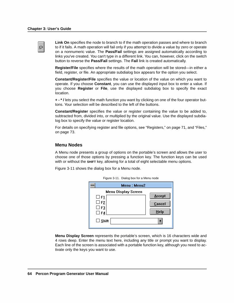
Chapter 3: User’s Guide
64 Percon Program Generator User Manual
DRAFT—12/16/96 1:57pmD:\DOCS\PPG\CH3.FMD
Link On specifies the node to branch to if the math operation passes and where to branchto if it fails. A math operation will fail only if you attempt to divide a value by zero or operateon a nonnumeric value. The Pass/Fail settings are assigned automatically according tolinks you've created. You can't type in a different link. You can, however, click on the switchbutton to reverse the Pass/Fail settings. The Fail link is created automatically.
Register/File specifies where the results of the math operation will be stored—in either afield, register, or file. An appropriate subdialog box appears for the option you select.
Constant/Register/File specifies the value or location of the value on which you want tooperate. If you choose Constant, you can use the displayed input box to enter a value. Ifyou choose Register or File, use the displayed subdialog box to specify the exactlocation.
+ - * / lets you select the math function you want by clicking on one of the four operator but-tons. Your selection will be described to the left of the buttons.
Constant/Register specifies the value or register containing the value to be added to,subtracted from, divided into, or multiplied by the original value. Use the displayed subdia-log box to specify the value or register location.
For details on specifying register and file options, see “Registers,” on page 71, and “Files,”on page 73.
Menu Nodes
A Menu node presents a group of options on the portable’s screen and allows the user tochoose one of those options by pressing a function key. The function keys can be usedwith or without the SHIFT key, allowing for a total of eight selectable menu options.
Figure 3-11 shows the dialog box for a Menu node.
Menu Display Screen represents the portable’s screen, which is 16 characters wide and4 rows deep. Enter the menu text here, including any title or prompt you want to display.Each line of the screen is associated with a portable function key, although you need to ac-tivate only the keys you want to use.
Figure 3-11. Dialog box for a Menu node

Modify Nodes
Percon Program Generator User Manual 65
DRAFT—12/16/96 1:57pmD:\DOCS\PPG\CH3.FMD
The F1–F4 check boxes activate or deactivate the function keys associated with each lineof the screen. If you want a function key to execute an option on the menu, select it here. Aradio button appears next to each selected check box, letting you use the drop-down list toset a node link for each option.
The Shift check box activates the Shift mode for each of the four function keys. When it isselected, options you set affect the function keys used with the portable’s SHIFT key (F5–F8). When you deselect this check box, the settings for the standard F1–F4 keys reappear.
Any function keys not activated in the Menu node dialog box will have no effect whenpressed.
The Link To drop-down list is not labeled in the dialog box. It includes the name of eachnode that the Menu node is linked to. Use it to connect a node link with a specific functionkey. Select the check box next to the function key, select the function key's radio button,and then select the node you want linked to the function key from this list. Repeat for everyfunction key you want to activate.
If the Menu node is not yet linked to other nodes, this list will be empty. Exit the dialog box,create the links, and then return to the dialog box.
If you simply want to display information on the portable’s screen, use a Display node in-stead of a Menu node (see “Display Nodes,” on page 60). To execute only one action re-gardless of which function key is displayed, use a Display node in conjunction with anInput node (see “Input Nodes,” on page 60).
Modify Nodes
Modify nodes let you change the contents of a given register or file. You can switch text toall uppercase or all lowercase, reverse the order of data, or delete data. You can also per-form a search-and-replace operation on data and clear the eighth bit of data. Figure 3-12shows the dialog box for a Modify node.
Figure 3-12. The dialog box for a Modify node

Chapter 3: User’s Guide
66 Percon Program Generator User Manual
DRAFT—12/16/96 1:57pmD:\DOCS\PPG\CH3.FMD
To Upper case changes all lowercase characters in the source string to uppercase.
To Lower case changes all uppercase characters in the source string to lowercase.
Search\Replace replaces all instances of a given string with a second given string. Whenthis option is selected, a right-arrow button appears next to the option. Click on it to displaythe Modify Search and Replace dialog box (see figure 3-13). Enter the string you want tosearch for in the Search for… input box and the string you want to replace it with in theReplace with… input box. Then select Accept.
Reverse reverses the order of data in the specified register. For example, if the registervalue were 123456, this option would reverse the order of characters in the string to654321.
Delete erases the contents of the specified register (or register field) or file (or record of afile).
Clear 8th Bit ensures that the specified data is in seven-bit ASCII format. If the data isstored in eight bits, this option clears the eighth bit. (The only case in which this might benecessary is with a file that has been downloaded from a PC.)
Data specifies the location of the data to modify. If you choose Register, select a registerfrom the displayed Register list box. To modify only one field of the register, select theField check box and select the template and field name from the displayed list boxes. (See“Registers,” on page 71.) If you choose File, select the file name from the displayed list.Select the Record check box to modify a specific record or field of the file. (See “Files,” onpage 73.)
Output Nodes
Output nodes send data to the portable’s display, to the serial port, or to the portable’s sys-tem software. You can send a defined constant or the contents of a register or file. Whensending data to the system, you can use special commands that sound a beep, set thesystem date or time, or reconfigure the portable. You can also send commands to the dis-play to reposition the cursor or erase the display.
Figure 3-14 shows the dialog box for an Output node.
Figure 3-13. The Modify Search and Replace dialog box

Verify Nodes
Percon Program Generator User Manual 67
DRAFT—12/16/96 1:57pmD:\DOCS\PPG\CH3.FMD
Output To specifies the channel over which data will be sent. The Display setting writesthe data on the portable’s screen, starting at the current cursor position. Serial sends thedata over the portable's serial port to a connected PC (to upload a file, for example). Sys-tem sends the data to the portable's operating system. This option is used with specialcommands (entered as constants) that sound a beep, set the system date or time, or posi-tion the cursor on the screen (see “Outputting Commands to the System,” on page 68).The Wedge option is for a PT 2000 portable only. It turns the portable into a “keyboardwedge,” sending data from the PT 2000 to a connected PC as if it were being typed on akeyboard.
Link On specifies the node to branch to if the output function is successful and where tobranch to if it fails. The Success/Failure settings are assigned automatically according tolinks you've created. You can't type in a different link. You can, however, click on theswitch button to reverse the Success/Failure settings. The Failure link is createdautomatically.
Source specifies the data or command to be transmitted (Constant) or the register or filecontaining the data. (See “Registers,” on page 71 and “Files,” on page 73.)
Verify Nodes
Verify nodes test data in a register or file to see if it's a certain type (ASCII, numeric, or al-phabetic). They can also verify that the data matches a given constant, matches the con-tents of a register, or falls within a given numeric or alphabetic range. Usually a Verify nodelinks to one node if the data passes the test and to another node if it doesn't. For example,a Verify node might check to see if the value scanned is numeric. If it is, the Verify nodemight branch to an Output node that sends the value to a file; otherwise, it might displayan error message.
Figure 3-14. The dialog box for an Output node
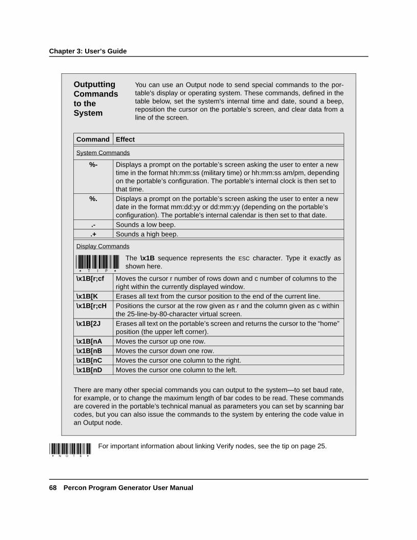
Chapter 3: User’s Guide
68 Percon Program Generator User Manual
DRAFT—12/16/96 1:57pmD:\DOCS\PPG\CH3.FMD
For important information about linking Verify nodes, see the tip on page 25.
Outputting Commands to the System
You can use an Output node to send special commands to the por-table's display or operating system. These commands, defined in thetable below, set the system's internal time and date, sound a beep,reposition the cursor on the portable’s screen, and clear data from aline of the screen.
Command Effect
System Commands
%- Displays a prompt on the portable’s screen asking the user to enter a new time in the format hh:mm:ss (military time) or hh:mm:ss am/pm, depending on the portable’s configuration. The portable's internal clock is then set to that time.
%. Displays a prompt on the portable’s screen asking the user to enter a new date in the format mm:dd:yy or dd:mm:yy (depending on the portable’s configuration). The portable's internal calendar is then set to that date.
.- Sounds a low beep..+ Sounds a high beep.
Display Commands
The \x1B sequence represents the ESC character. Type it exactly asshown here.
\x1B[r;cf Moves the cursor r number of rows down and c number of columns to the right within the currently displayed window.
\x1B[K Erases all text from the cursor position to the end of the current line.\x1B[r;cH Positions the cursor at the row given as r and the column given as c within
the 25-line-by-80-character virtual screen.\x1B[2J Erases all text on the portable’s screen and returns the cursor to the “home”
position (the upper left corner).\x1B[nA Moves the cursor up one row.\x1B[nB Moves the cursor down one row.\x1B[nC Moves the cursor one column to the right.\x1B[nD Moves the cursor one column to the left.
There are many other special commands you can output to the system—to set baud rate,for example, or to change the maximum length of bar codes to be read. These commandsare covered in the portable’s technical manual as parameters you can set by scanning barcodes, but you can also issue the commands to the system by entering the code value inan Output node.

Verify Nodes
Percon Program Generator User Manual 69
DRAFT—12/16/96 1:57pmD:\DOCS\PPG\CH3.FMD
Figure 3-15 shows the dialog box for a Verify node.
Type verifies that the tested data is ASCII (hex values 00 to 7F), numeric (hex values 30 to39), or alphabetic (hex values 40 to 5A and 60 to 7A). Numeric values include the charac-ters + (plus), - (minus), and . (period). ASCII values include both numeric and alphabeticcharacters; if it doesn't matter to you whether the data is numbers or letters, use the ASCIIsetting.
Match specifies the data to be tested against. The None setting requires no match; it testsonly on the basis of type. If you select any of the other three radio buttons, a right-arrowbutton appears next to the option. Click on it to display a dialog box for entering a con-stant, range, or register name. (See “Specifying a Range to Match,” below, for informationon setting up a range. See “Registers,” on page 71, for details on specifying a registerlocation.)
Figure 3-15. The dialog box for a Verify node

Chapter 3: User’s Guide
70 Percon Program Generator User Manual
DRAFT—12/16/96 1:57pmD:\DOCS\PPG\CH3.FMD
Ignore Case verifies the data match regardless of capitalization. If you want the data to becase specific, don't select this option.
Use Store Index In Register when you're verifying data in a file. This option stores in aregister the number of the first record in the file that passes the verification. (If there is nomatch, it stores the position of the last record.) When this check box is selected, a registerlist box appears. Select a register name from the list, or type in an unlisted name to createa new register (see “Registers,” on page 71). This option is disabled when the VerifySource option is set to Register.
Link On specifies the node to branch to if the verify function is successful and where tobranch to if it fails. The Pass/Fail settings are assigned automatically according to linksyou've created. You can't type in a different link. You can, however, click on the switch but-ton to reverse the Pass/Fail settings.
Specifying a Range to Match
When verifying data, you can use the Match Range setting to verifythat a number falls within a given range or that a text string falls withina given alphabetic range. When you select the Range radio button forthe Match option, a right-arrow button appears next to the option.Click on it to display the Verify Range dialog box (see the figurebelow). Use this box to define both the low and high values of therange.
For the lowest and highest values in the range, you can specify eithera constant or the contents of a given register. To specify a constant,select the Constant radio button and type in a number or text string.To specify a register, select the Register radio button and select aregister name from the drop-down list. Select Accept to return to theVerify Node dialog box.

Controlling Data Flow
Percon Program Generator User Manual 71
DRAFT—12/16/96 1:57pmD:\DOCS\PPG\CH3.FMD
Verify Source specifies the location of the data to be verified—either a register or a file.The Sorted setting uses a binary search algorithm to speed up file searches. This optionworks only with presorted files. Use the displayed subdialog box to specify the exact regis-ter or file (see “Using a Register as a Source,” on page 71, and “Using a File as a Source,”on page 73).
Controlling Data FlowSo far, there has been a lot of focus on program control and how the portable’s programwill work from the user's viewpoint. Another essential piece, however, is how data ishandled by the program. Since the program's result is a file of collected data, it's importantto spend some time thinking about the purpose of this file and how you want it organized.You may also want to work with data files that are downloaded into the portable or exam-ine portions of collected data.
Three important tools can help you control the flow of data:
• Registers store data temporarily. When you scan or enter a string of data, it is usuallyplaced in a register before it is copied into a portable file. You can also use registers tostore user response to a prompt, the index of a record in a file, and so on.
• Files hold data in the portable until it can be uploaded to a PC. Usually after input data isverified, it is inserted in a portable file. The file expands as more data is added. Files canalso be used to hold database information downloaded from a computer. This informa-tion can then be used to verify scanned data or for other purposes.
• Templates let you combine data stored in different registers or break down data in asingle register into fields. You can use them to set up records in a file so that the datacan easily be transferred to a database or spreadsheet file. You can also use them toaccess portions of data in a register.
The following sections describe how to specify a register in which to store data or copydata from, how to specify a source or destination file for data, and how to create a tem-plate for breaking down or combining data. The last two sections give examples of usingregisters, templates, and files to control data flow.
Registers
A register is a temporary holding place for data. Whenever a data source or destination isrequested in a node dialog box, Register is given as an option. When you select it, theRegister subdialog box appears so that you can specify an existing register or create anew one.
USING A REGISTER AS A SOURCE When you choose Register as the setting for asource option, the subdialog box shown in figure 3-16 appears.

Chapter 3: User’s Guide
72 Percon Program Generator User Manual
DRAFT—12/16/96 1:57pmD:\DOCS\PPG\CH3.FMD
Click on the down-arrow button next to the Register list box to display a list of existingregisters. To specify one of these registers, just select it from the list. To create and specifya new register, type a name in the list box.
To specify only a given field of the register, select the Field check box. The Template andField list boxes appear (see “Specifying a Register Field,” on page 73).
USING A REGISTER AS A DESTINATION When you choose Register as the setting for adestination option, the Register subdialog box includes options for data placement (seefigure 3-17).
Specify the register name by selecting it from the drop-down list or typing it in. Then selectone of the following radio buttons:
• Insert places the data at the beginning of the register, before any existing data.
• Replace replaces any data previously stored in the register.
• Append adds the data to the end of the register, after any existing data.
• Field stores the data in a specified field of the register (see the following section).
Figure 3-16. The Source Register subdialog box
Figure 3-17. The Destination Register subdialog box

Specifying a Register Field
Percon Program Generator User Manual 73
DRAFT—12/16/96 1:57pmD:\DOCS\PPG\CH3.FMD
SPECIFYING A REGISTER FIELD If you select the Field option in either Register subdia-log box, the box changes to include Template and Field list boxes (see figure 3-18).
Select the template you want to use from the Template drop-down list, and then select thefield. You can use the right-arrow button at the right of the Template list box to alter or cre-ate templates (see “Creating a Template,” on page 74).
Files
Portable files are used to store data that has been either input via the portable’s wand ordata keys or downloaded from a PC file through the serial port. Each entry in a file iscalled a record, and the records in each file are numbered, with 1 as the first record.
There are two types of file settings in portable dialog boxes. Source file settings specify afile or record in a file to be read from. Destination file settings determine a file or record tobe written to.
USING A FILE AS A SOURCE When you select File as the setting for a source option,the subdialog box shown in figure 3-19 appears.
Select the name of the file you want from the drop-down list, or type in a name to create anew file. To specify only a certain record of the file, select the Record check box. The sub-dialog box then expands, as shown in figure 3-20.
Figure 3-18. Template and Field list boxes
Figure 3-19. The Source File subdialog box
Figure 3-20. The Record Selection options

Chapter 3: User’s Guide
74 Percon Program Generator User Manual
DRAFT—12/16/96 1:57pmD:\DOCS\PPG\CH3.FMD
Select the First or Last radio button to specify the first or last record in the file. To specifya record number, select Number and enter the number in the input box that appears. Touse a record number stored in a register, select Index and use the displayed Register listbox to specify the register (see “Using a Register as a Source,” on page 71).
USING A FILE AS A DESTINATION If you choose File as the setting for a destination op-tion, the dialog box shown in figure 3-21 appears.
Choose the file you want from the drop-down list, or enter a file name in the list box. Thenselect one of the following radio buttons:
• Insert places the data before a given record. When this option is selected, further radiobuttons appear (First, Last, Index, and Number) that let you specify a certain record inthe file. (These options are described in the preceding section, “Using a File as aSource.”)
• Replace replaces a given record. Use the displayed radio buttons to specify the exactrecord.
• Append adds the data to the end of the existing file.
• Sorted inserts the record of data into the file based on ascending ASCII value. Use thisto insert records into a file that has already been sorted to maintain the proper order ofthe records in the file.
Creating a Template
A template is a structure that you can define and use to alter the way in which collecteddata is stored.
The most common use of templates is to take data from two or more registers and tiethem together in a single register. This allows you to collect and store more than one typeof information. For example, your program could ask the user to enter first a location codefor an item and then the item number. The template would combine each set of values in aregister, and the value pair could then be copied to a file as fields in a single record. Datain the file would be arranged either in fields of a fixed size, as in the following:
Figure 3-21. The Destination File subdialog box

Creating a Template
Percon Program Generator User Manual 75
DRAFT—12/16/96 1:57pmD:\DOCS\PPG\CH3.FMD
2348 49384848 3939488 29383229 832928185 39203828 282930
or with delimiters separating variable-length fields in the record, as in the following:
2483, 49384848, 3939488, 29383229, 832928185, 39203828, 282930
Templates can be used only on registers, not on records in files.
The data file can then easily be translated for use by a database or spreadsheet program.The first value in each record would go into a Location field, the second value would gointo an Item Number field, and the program would pair the values appropriately.
Another use of templates is to break down data stored in one register into two or more reg-ister fields (for example, to strip out the first section of a code).
To create a template, complete the following steps:
1. Double-click on an Input node (or any node that has a Register option), and selectRegister as an option setting.
2. Specify a new register for storing the data, or just use the Default Register setting.
3. Select the Field check box next to the Register list box. The subdialog box expands,as shown in figure 3-22.
Field 1 Field 2
Figure 3-22. The expanded Register subdialog box

Chapter 3: User’s Guide
76 Percon Program Generator User Manual
DRAFT—12/16/96 1:57pmD:\DOCS\PPG\CH3.FMD
4. Click on the right-arrow button to the right of the Template list box to display theDefine Template subdialog box (see figure 3-23).
5. In the Template input box, enter the name you want to give the new template.
To modify an existing template, choose a name from the drop-down list.
6. The Fields list box includes the names of all fields assigned to the template. (Thereare none at this point.) The Define Fields list box lists all defined fields you can assignto the template. It includes system-defined fields, such as Month and Hours. To addyour own fields to the Fields list, click on the right-arrow button to the right of theDefine Fields list box. The Define Field subdialog box appears (see figure 3-24).
7. In the Field input box, enter the name you want to give the first field for the template.
8. If you want the fields to be arranged in columns, select the Fixed Length radio buttonand enter the desired column width (in number of characters). This number should beat least the maximum number of characters to be entered in the field—more if youwant to create space between the columns.
To allow for variable-length entries, with fields separated by a delimiter (such as acomma), select the Variable Length radio button and enter the character you want touse as a delimiter.
Figure 3-23. The Define Template subdialog box
Figure 3-24. The Define Field subdialog box

Modifying a Pick List
Percon Program Generator User Manual 77
DRAFT—12/16/96 1:57pmD:\DOCS\PPG\CH3.FMD
9. Repeat the last step for each field you want to define. When you're done, click on theDone button to return to the Define Template dialog box.
10. Select the down-arrow button next to the Define Fields list box and you'll see yournew fields added to the list. Select the first field you want in your template. With thatfield displayed in the input box, select the Add button to copy it to the Fields listabove.
11. Repeat step 10 for each field you want included in the template. Add the fields in theorder in which you want them to be arranged in the data records (although you caninput data in the fields in any order). When you've added all the fields you want, selectthe down-arrow button next to the Fields list box to display the list, and then selectDone.
12. Back in the Register subdialog box for the Input node, select your newly defined tem-plate from the Template drop-down list.
13. From the Field drop-down list, select the field that data for that particular node shouldbe stored in or retrieved from.
14. For each Input node handling data for one of the template's fields, display the Inputnode dialog box, set the Destination option to Register, and select the Field checkbox. Then select the template from the drop-down list and select the field you wantthat data to be stored in. If you specified a particular register for storing the templatedata (in step 2), use that same register setting here.
Once you've created a template, it is added to the template drop-down list and you canuse it with any register.
Modifying a Pick List
Suppose you run a small TV-repair shop and you keep track of your parts inventory on aPC in your shop office. Instead of running to your office computer each time you use apart, you want to be able to use the portable to adjust your inventory during the day andthen update your PC inventory file each night.
You need to create a portable program that will download the latest inventory file from yourPC as a “pick list” and modify it as necessary to keep the inventory current. Each time youtake a part off the shelf, you would scan its part-number label. The portable’s programwould then subtract 1 from the quantity of items for that part number in the pick list. At theend of the day, you could use an upload function in the portable’s program to copy the ad-justed data file back to your PC.
You could use registers, files, and templates to accomplish this by completing the followingsteps:
1. Use an Input node to download the pick list from the PC to a portable file.
2. Use another Input node to store a scanned part number in a register named PartNumber.

Chapter 3: User’s Guide
78 Percon Program Generator User Manual
DRAFT—12/16/96 1:57pmD:\DOCS\PPG\CH3.FMD
3. Since templates cannot be used directly on files, you can create a second file thatcontains only part numbers. To do this, mark the end of the file by appending it with atext flag, such as END. Then copy the first record in the file into a register. Use a tem-plate in a Copy node to copy the part-number portion of the register into its own fileand the rest of the data into another file. Continue until the last record (named END) isreached.
Another way to achieve this is by downloading two files separately.
4. Use a Verify node to search through the new part-number file for the number stored inthe Part Number register. Store the index of the matched record in a register namedIndex.
5. Use the number stored in the Index register along with another Modify node to pin-point the corresponding record in the original pick list.
6. Use a Copy node to access the quantity field for that record and store it in a registernamed Quantity.
7. Use a Math node to subtract 1 from the value in the Quantity register.
8. Use a Copy node to copy the modified value back into the pick list in its originalposition.
Breaking Down Data in a Register
Now suppose that you own a catalog business. As you ship packages out, you scan a la-bel that includes information about the destination. The first character of each label identi-fies the destination region: North, West, South, or East. You want to alter your portableprogram so that the data is stored in four different files, one for each region.
You need to create a template that breaks down the scanned code into two fields, one forthe region character and one for the rest. The template should then examine the regionfield to determine which file the scanned data should be copied to—North, West, South, orEast.
To create this template, complete the following steps:
1. Create a Verify node that uses a template to check whether the character in theRegion field is N and, if it is, proceeds to a Copy node that copies the contents of theinput register to a file called North.
2. Create a Verify node that checks whether the character is W and, if it is, copies theinput code to a file called West.
3. Create two more Verify and Copy node pairs to copy data labeled South and East tothe appropriate files.

Editing a Flow Chart
Percon Program Generator User Manual 79
DRAFT—12/16/96 1:57pmD:\DOCS\PPG\CH3.FMD
Editing a Flow ChartAfter you've created a program flow chart, you can modify it at any time. You can moveand add frames and nodes, adjust links, and change options in node dialog boxes. Youcan use the following commands in the Edit menu to make changes to a flow chart:
The keystrokes given in parentheses allow you to use the menu commands without goingthrough the Edit menu. (For complete information about keyboard shortcuts, see yourMicrosoft Windows user’s guide.)
• Cut (SHIFT+DELETE) removes the selected node or frame from the flow chart and storesit in the Windows Clipboard. Any links to the frame or node are removed as well.
• Copy (CTRL+INSERT) copies the selected node or frame to the Clipboard without remov-ing it from the flow chart.
• Paste (SHIFT+INSERT) inserts the node or frame stored in the Clipboard in the upper leftcorner of the screen.
• Delete (DELETE) removes the selected node or frame (and its links) without storing it inthe Clipboard.
• Rename displays the Name dialog box for the selected node or frame so that you canrename it.
Cutting, Copying, and Pasting
You can use the Cut, Copy, and Paste commands to move and copy parts of a flow chartfrom one frame to another or from one program to another. These commands operate onframes and nodes just like they do on text or graphics in other Windows applications.
To move an object from one frame or program to another, select it and choose EditðCut.To copy an object, select EditðCopy. Then go to where you want the cut or copies objectinserted and choose EditðPaste. The object is pasted in the top left corner of the window,but you can drag it with the mouse to reposition it.
In the Nodes level, you can select more than one object by drawing a box around the ob-jects with the mouse. You can then cut or copy all the objects in the box at one time andplace them somewhere else. You can also drag all the boxed objects with the mouse.
Fields and templates cannot be moved or copied between programs.

Chapter 3: User’s Guide
80 Percon Program Generator User Manual
DRAFT—12/16/96 1:57pmD:\DOCS\PPG\CH3.FMD
Deleting Nodes and Frames
To delete a node or frame, simply select it and choose EditðDelete or press the DELETE
key. The object is removed along with any links to or from it.
There's no “undo” command to reverse a deletion you make accidentally. For that reason,it's a good idea to use Cut instead of Delete to remove nodes and frames. That way, if youdelete something by accident, you can use Paste to bring it back.
Renaming Nodes and Frames
When you create a node or frame, it is automatically named Node# or Frame#, where # isthe number of nodes in the frame or the number of frames in the program. It's helpful togive a node or frame a more descriptive name so that its purpose in the program is easilyidentified.
To rename a frame or node, move the pointer to it and click the right mouse button, or se-lect the frame and choose EditðRename. The Frame Name or Node Name dialog boxappears, showing the currently assigned name (see figure 3-25). Type the new name inthe input box, and select Ok or press ENTER. The new name then appears in the frame ornode.
Figure 3-25. The Node Name dialog box
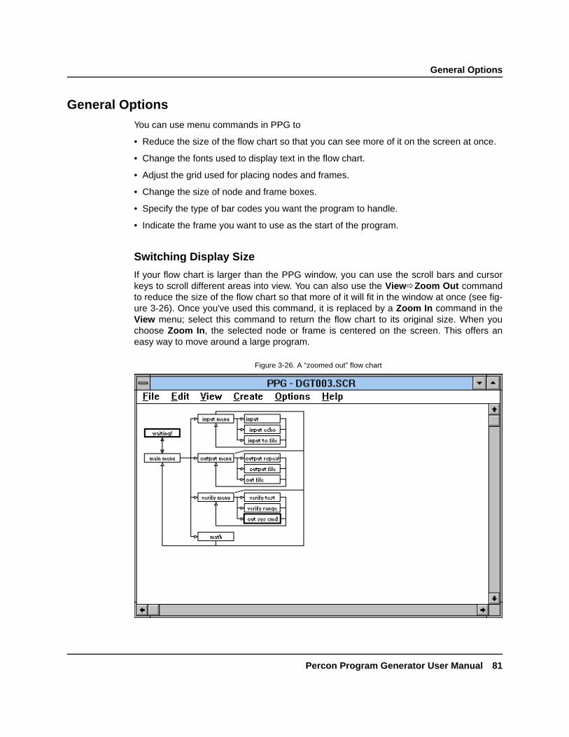
General Options
Percon Program Generator User Manual 81
DRAFT—12/16/96 1:57pmD:\DOCS\PPG\CH3.FMD
General OptionsYou can use menu commands in PPG to
• Reduce the size of the flow chart so that you can see more of it on the screen at once.
• Change the fonts used to display text in the flow chart.
• Adjust the grid used for placing nodes and frames.
• Change the size of node and frame boxes.
• Specify the type of bar codes you want the program to handle.
• Indicate the frame you want to use as the start of the program.
Switching Display Size
If your flow chart is larger than the PPG window, you can use the scroll bars and cursorkeys to scroll different areas into view. You can also use the ViewðZoom Out commandto reduce the size of the flow chart so that more of it will fit in the window at once (see fig-ure 3-26). Once you've used this command, it is replaced by a Zoom In command in theView menu; select this command to return the flow chart to its original size. When youchoose Zoom In, the selected node or frame is centered on the screen. This offers aneasy way to move around a large program.
Figure 3-26. A “zoomed out” flow chart
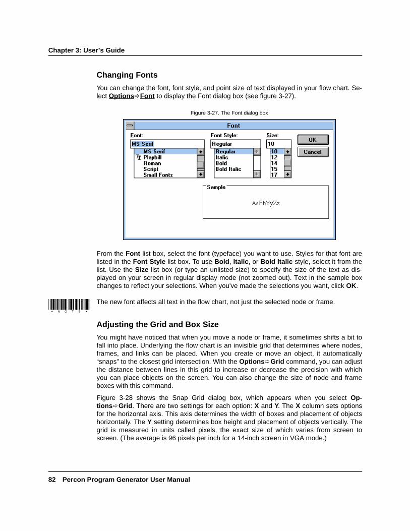
Chapter 3: User’s Guide
82 Percon Program Generator User Manual
DRAFT—12/16/96 1:57pmD:\DOCS\PPG\CH3.FMD
Changing Fonts
You can change the font, font style, and point size of text displayed in your flow chart. Se-lect OptionsðFont to display the Font dialog box (see figure 3-27).
From the Font list box, select the font (typeface) you want to use. Styles for that font arelisted in the Font Style list box. To use Bold, Italic, or Bold Italic style, select it from thelist. Use the Size list box (or type an unlisted size) to specify the size of the text as dis-played on your screen in regular display mode (not zoomed out). Text in the sample boxchanges to reflect your selections. When you've made the selections you want, click OK.
The new font affects all text in the flow chart, not just the selected node or frame.
Adjusting the Grid and Box Size
You might have noticed that when you move a node or frame, it sometimes shifts a bit tofall into place. Underlying the flow chart is an invisible grid that determines where nodes,frames, and links can be placed. When you create or move an object, it automatically“snaps” to the closest grid intersection. With the OptionsðGrid command, you can adjustthe distance between lines in this grid to increase or decrease the precision with whichyou can place objects on the screen. You can also change the size of node and frameboxes with this command.
Figure 3-28 shows the Snap Grid dialog box, which appears when you select Op-tionsðGrid. There are two settings for each option: X and Y. The X column sets optionsfor the horizontal axis. This axis determines the width of boxes and placement of objectshorizontally. The Y setting determines box height and placement of objects vertically. Thegrid is measured in units called pixels, the exact size of which varies from screen toscreen. (The average is 96 pixels per inch for a 14-inch screen in VGA mode.)
Figure 3-27. The Font dialog box

Specifying Bar Code Type
Percon Program Generator User Manual 83
DRAFT—12/16/96 1:57pmD:\DOCS\PPG\CH3.FMD
To be able to place objects very precisely on the screen, decrease the space between gridlines by lowering the Frame/Node values. To make it easier to line objects up on thescreen, increase these values, expanding the space between grid lines. If you're findingthat some of the text in your nodes or frames is getting cut off, you may want to increasethe box size or decrease the font size.
When you're done, select Ok to exit the dialog box. All objects in the current flow chart areaffected immediately.
The grid map for links is automatically set to half of whatever the Frame/Node grid is setto. For example, with the default Frame/Node setting of 10/10, the link grid is set to 5/5.
Specifying Bar Code Type
There are several types of bar codes that can be generated by bar code printing programs,including Code 39, I 2/5, UPC-EAN, Codabar, and Code 128. (UPC-EAN codes are thestandard codes found on consumer items.) Percon portables can always read Code 39 barcodes, but you must specify which other code types you want to decode.
To specify the types of bar codes that a program can read, select OptionsðSet BarCodes and choose the symbologies you want to be able to decode from the Bar CodeVersion dialog box (see figure 3-29).
Figure 3-28. The Snap Grid dialog box
Figure 3-29. The Bar Code Version dialog box

Chapter 3: User’s Guide
84 Percon Program Generator User Manual
DRAFT—12/16/96 1:57pmD:\DOCS\PPG\CH3.FMD
The number of types that can be decoded is limited by your portable's memory. Possiblecombinations are:
I 2/5, Codabar, Code 1282/5, UPC/EAN2/5, Codabar2/5, Code 128
UPC/EAN, CodabarUPC/EAN, Code 128
When you've selected the symbologies you want the portable to be able to decode, selectOk. If the selected symbologies require more memory than the portable has available, amessage box appears. Deselect one or two symbologies and try again.
The bar code settings are stored with the current flow chart file, and so they are in effecteach time you work with that file.
Setting a Starting Place
A program's starting place is the frame with which the program begins. By default, the por-table’s program starts with the first frame that was created. To start the program with a dif-ferent frame, use the OptionsðSet Start command to set a starting place.
When you choose OptionsðSet Start, the mouse pointer changes to a rounded box la-beled “START”. Move it to the frame you want the program to start with, and click the leftmouse button. The specified frame appears with a double-line border.
The Set Start command is used only for frames. It is dimmed in the Nodes view and can-not be selected.
Working with Program Source FilesLike most software programs, PPG stores data in files. To save a program flow chart, youmust copy it into a file. You can then call it up and modify it at any time. Commands on thePPG File menu let you open an existing file, save a file, close a file, start a new file, andprint a file.
Don't confuse PPG program source files with those used to store data in the Percon por-table. The portable has its own type of files used for storage (see “Controlling Data Flow,”on page 71); although they can be transferred to a DOS file on your PC, they are not di-rectly compatible.

Opening a File
Percon Program Generator User Manual 85
DRAFT—12/16/96 1:57pmD:\DOCS\PPG\CH3.FMD
Opening a File
To open an existing program source file, select FileðOpen from the menu. If the PPG win-dow currently contains a flow chart, a dialog box appears, asking if you want to savechanges to the flow chart. Select Yes to save the file or No to discard changes. The Opendialog box then appears (see figure 3-30).
By default, the File list shows all program source (.SCR) files in the PPG31 directory. If thefile you want is located elsewhere, choose the drive and directory from those lists, or typethem in the input box. Select the file you want to open from the File list or type its name inthe input box, and select OK. The specified file is loaded into the PPG window.
When you compile a program source file (using the FileðDownload Program com-mand—see page 92), PPG creates a new file that is suitable for programming your por-table. The original .SCR file remains intact, and the compiled file is given the same name,but with a .HEX extension. It is this .HEX file that is downloaded into the portable. Onceyou've compiled a program source file, you can use the FileðOpen command in thePercon Portable Programmer window to download its .HEX file into your portable withouthaving to recompile it. (You can also load a .HEX file from DOS using the PDPROG appli-cation in the PPG31 directory. Enter pdprog /? on the DOS command line for informationabout using the program.)
Figure 3-30. The Open dialog box

Chapter 3: User’s Guide
86 Percon Program Generator User Manual
DRAFT—12/16/96 1:57pmD:\DOCS\PPG\CH3.FMD
Saving a File
To save a newly created file for the first time (or to save an existing file with a differentname), choose FileðSave As. The Save As dialog box appears (see figure 3-31).
Enter a name for the new file in the File Name input box. The file list below it shows thenames of all existing source-program files in the PPG31 directory. Unless you want to over-write the contents of an existing file, use a unique name. PPG automatically gives the pro-gram file an .SCR extension.
By default, the file is saved in the directory in which you installed PPG, and this is wherePPG will look when you go to open a file. If you want to store the file elsewhere, select thedrive and directory from those lists, or type them before the file name in the input box.
Select OK to save the program flow chart in the specified file. If a file of that name alreadyexists in the specified directory, a dialog box appears, asking if you want to replace the ex-isting file. Select Yes to replace the file or No to return to the Save As dialog box, whereyou can give the file another name or place it in another location.
Once you've saved your flow chart in a file, you can use FileðSave to save changes to itwithout being prompted for a file name again. To save the file under a different name or ina different location, use FileðSave As.
Starting a New File
To clear the PPG window so that you can start a new flow chart, select FileðNew. A dia-log box appears, asking if you want to save changes to the current flow chart. Choose Yesor No. If you choose Yes and the flow chart is unnamed, the Save As dialog box appears(see figure 3-31) so that you can name the file to store it in. If you choose Yes and the fileis already named, it will be saved automatically. The current flow chart is then removedfrom the window so that you can start fresh.
Figure 3-31. The Save As dialog box

Printing a File
Percon Program Generator User Manual 87
DRAFT—12/16/96 1:57pmD:\DOCS\PPG\CH3.FMD
Printing a File
To print the current view of a program flow chart, select FileðPrint. The displayed Framesor Nodes view is sent to the printer, and a message box appears. Select Cancel in themessage box to abort printing.
You can print only one view of a flow chart at a time.
Using the Program EmulatorThe emulator feature of PPG lets you test your program source file before loading it intoyour portable. It runs your program in a separate window that is modeled after the face ofthe portable. It shows what would appear in the portable’s display at each step and re-sponds to your input just as the program would. You can simulate scanning codes, press-ing function keys, and entering data with the data keys. If there are any problems with theprogram, you can pinpoint them and make corrections before programming the portable.
You cannot save or access files in the emulator.
The Emulation Window
To load the current program into the Emulation window, select ViewðEmulation. The Em-ulation window appears (see figure 3-32). The name of the emulated program's currentframe and node are displayed in the title bar. Commands on the menu bar of the windowlet you run the program and set emulation options.
Figure 3-32. The Emulation window

Chapter 3: User’s Guide
88 Percon Program Generator User Manual
DRAFT—12/16/96 1:57pmD:\DOCS\PPG\CH3.FMD
By default, the Emulation window is modeled after the face of a Percon PocketReader. Theright side of the window simulates the PocketReader’s screen and displays its contents ateach point in the program. Below and to the left of the screen are data and function keys.You can click on any of these keys with a mouse to simulate pressing them. An input boxat the bottom of the screen displays data you enter, and a check box lets you enable ordisable the input timeout option (if allowed). When timeout is enabled, the timeout count-down is displayed in the box at the bottom right of the window.
If you select OptionsðPT 2000 from the menu, the Emulation window changes to repre-sent the face of a PT 2000 portable (see figure 3-33).
Emulation Menu Options
Both Emulation windows include a menu bar at the top that contains the followingcommands:
• Run begins execution of the program. The program will continues until it comes to apoint that requires input or it encounters a breakpoint (see Break).
• Step executes the next step of the program and then stops. This allows you to “walkthrough” the program one node at a time. The node about to be executed is shown in thetitle bar.
• Reset takes the emulator back to the first node of the program's start frame.
• Break lets you specify certain nodes in your program as breakpoints, at which the emu-lator will stop until you select the Run or Step command (see “Setting Breakpoints,” onpage 89).
• Options lets you switch between the PocketReader and PT 2000 display styles. It alsogives you the following options:
• Watch lets you view the contents of specified registers in a separate window as theprogram is executed (see “Watching Register Contents,” on page 90).
• Trace displays a list of each step executed by the emulator in a separate window (see“Tracing Program Execution,” on page 91).
Figure 3-33. The PT 2000 Emulation window

Setting Breakpoints
Percon Program Generator User Manual 89
DRAFT—12/16/96 1:57pmD:\DOCS\PPG\CH3.FMD
To protect existing data files during testing, the program emulator won't store data in files.
Use the Break, Watch, and Trace commands to set up options for the emulator. Then se-lect Run or Step to execute the program. During execution, when an Input node isreached, the menu bar changes to contain the following commands:
• Wand passes the data in the input box to the portable’s emulator as if it were scannedwith the wand. If wand input is not allowed at the current point in the program, this com-mand is dimmed and can't be selected.
• Serial passes the data in the input box to the portable’s emulator as if it were transmittedover the serial port. If serial input is not allowed, this command is dimmed and can’t beselected.
• Timeout simulates the passage of a given amount of time with no input. The timeoutlength is set in an Input node and is counted down in the box in the bottom-right cornerof the Emulation window. This command is available only if the current Input node has atimeout setting and the Enable Timeout check box is selected in the Emulation window.
• Stop halts execution of the program and restores the original commands on the menubar.
When the program is at a point where it requires input from the user, you can click on dataor function keys (or type alphanumeric keys on the keyboard) to enter data in the Emula-tion window’s input box. Then click on the ENTER button to simulate key entry, or selectWand or Serial to simulate scanning or serial input. The program processes the input andcontinues with the next step.
To enter a letter with the keys in the Emulation window, first click on the Shift button untilthe letter you want is displayed on one of the keys. Then select that key. Although thereare only four function keys, F1 through F4, you can also access F5 through F8 by pressingthe Shift button until those key identifications appear.
When you're done working with the program, select Stop in the menu bar to haltexecution. When you're done with the program emulator, double-click on the Emulationwindow's Control-menu box, or select Close from the Control menu. The Emulation win-dow closes, and the program returns to the PPG window.
Setting Breakpoints
If there are certain areas of your program that you want to focus in on, you can set abreakpoint at one or more nodes. When you execute the program (with the Run com-mand), the emulator will pause execution wherever there is a breakpoint. You can then useRun or Step to resume execution.
To set a breakpoint, select Break from the menu bar. (If you're running a program, you'llhave to stop it first.) Then move the mouse pointer to the flow chart, where it becomes arounded box labeled “BREAK”. Position the BREAK pointer on the node where you wantto pause execution, and click the left mouse button.

Chapter 3: User’s Guide
90 Percon Program Generator User Manual
DRAFT—12/16/96 1:57pmD:\DOCS\PPG\CH3.FMD
You can move the Emulation window to another part of the screen if you need to click on anode that is underneath it. If the node is in another frame, you'll need to display thatframe’s nodes before selecting Break.
Nodes that you specify as breakpoints are indicated by red lettering on the screen. To re-move a breakpoint from a node, choose the Break command and click on the node again.
Watching Register Contents
To make sure that data is being stored correctly in registers, you can use the Watch com-mand to view register contents while the emulator runs the program. When you select Op-tionsðWatch from the Emulation window menu, the PPG Watch window appears (seefigure 3-34). You can reposition or resize the window.
The PPG Watch window is initially set up to show the contents of the default register. Toview the contents of other registers, choose SetUp from the PPG Watch menu bar to dis-play the Setup Watch dialog box (see figure 3-35).
If you're running a program, you'll have to stop it before selecting SetUp.
Figure 3-34. The PPG Watch window
Figure 3-35. The Setup Watch dialog box

Tracing Program Execution
Percon Program Generator User Manual 91
DRAFT—12/16/96 1:57pmD:\DOCS\PPG\CH3.FMD
The top part of the dialog box lists all registers available for use in the program, includingstandard PPG registers. The bottom part lists registers that will be tracked in the PPGWatch window. To add a register to the Watch list, select the register in the Registers listand then select Add. To remove a register from the Watch list, select it and then selectRemove. When the Watch list includes all the registers whose contents you want to viewduring emulation, select Ok.
When you run the program in the Emulation window, the PPG Watch window shows thename of each register in the Watch list along with its current contents. You can see whatdata is entered into each register when it is entered.
To close the PPG Watch window, select OptionsðWatch from the Emulation windowmenu again. (If you're running a program, stop it first.)
Tracing Program Execution
For a detailed log of every step taken by the emulated program, select OptionsðTracefrom the Emulation window menu. This opens the PPG Trace window (see figure 3-36),which lists all emulator activity, including the following:
• The name of each frame and node executed by the emulator.
• The value of any register entered through an Input node.
• The value of any register that changes because of a step in any node.
You can drag the sides of the PPG Trace window to resize it, and you can drag its title barto reposition it on the screen. Use the scroll bars (when they appear) to scroll through thelist of actions.
To close the Trace window, select Stop in the Emulation window, if necessary, to halt pro-gram execution, and then select OptionsðTrace again.
Figure 3-36. The PPG Trace window

Chapter 3: User’s Guide
92 Percon Program Generator User Manual
DRAFT—12/16/96 1:57pmD:\DOCS\PPG\CH3.FMD
Downloading a ProgramTo load a program into your Percon portable, complete the following steps:
1. Connect the 25-pin connector of the cable to a serial port on your computer. (If youdon't have a 25-pin serial port, use the 25-to-9-pin adapter supplied with yourportable.)
2. Connect the other end of the cable to the portable.
3. Turn the portable on.
4. In the PPG window, select FileðDownload Program from the menu. If a dialog boxappears, asking if you want to save changes to the file, answer Yes or No.
The Percon Portable Compiler window appears momentarily as PPG compiles theprogram, translating it into a language understood by the portable. The original .SCR
file remains intact, and the compiled file is given the same name, but with a .HEX
extension. It is this .HEX file that is downloaded into the portable.
While a program is downloading, you can work in another application window.
When compiling is complete, the Percon Portable Programmer window appears, dis-playing the message “Initiating Download.” If connection is successful, the windowshows further messages as the compiled .HEX file is loaded into the portable. The per-centage of completion is displayed as the programming progresses.
When downloading is complete, you'll see the message “Portable successfully pro-grammed” in the Percon Portable Programmer window, and the program's Main Menuwill appear in the portable’s display.
5. Double-click on the Percon Portable Programmer window's Control-menu box orselect FileðExit to close the window.
Most of the time, downloading is very quick. Downloading the compiled program file takesapproximately 15 seconds. If the bar code settings for the program (see “Specifying BarCode Type,” on page 83) are different from those currently set in the portable, they will bedownloaded as well, taking an additional 15 seconds or so.
The downloader also checks the version number of the portable's operating system. If it isdifferent from PPG's version, it downloads the operating system along with the program;this can take two or three minutes. When the system software is being upgraded with anew release, progress is shown as a percentage in the Percon Portable Programmerwindow.
If you remove all power sources while downloading only the com-piled program or bar code settings, you will have to program the portable again. However,if you are downloading the operating system to the portable, the portable could be leftwithout an operating system; you would have to return it to Percon for servicing.

Transferring Data to and from the Portable
Percon Program Generator User Manual 93
DRAFT—12/16/96 1:57pmD:\DOCS\PPG\CH3.FMD
If you're downloading a program file to several portables, or if you switch between two ormore programs in a portable, you may find it easier to download the program's compiledfile, rather than recompiling the source file each time. Once you're in the Percon PortableProgrammer window, you can use the FileðOpen command to download a previouslycompiled .HEX file. This command displays the standard Open dialog box (see page 85),listing all .HEX files in the PPG31 directory. Specify a file and select OK. Downloading be-gins immediately.
To access the Percon Portable Programmer window directly from Windows, double-clickon the PROG icon in the Percon PPG31 program group.
Transferring Data to and from the PortablePPG comes with two programs that you can use to transfer data between your computerand a portable:
• PTFER is a Windows application, with its own icon in the Percon PPG31 group window.
• PDTFER is a DOS program that you run by issuing commands on the DOS commandline.
Also available from Percon are two utilities for transferring data to and from a Macintosh orUNIX computer:
• MACTFER is a Macintosh program you can use to communicate with a Macintosh.
• updtfer is a UNIX program you can use to communicate with a UNIX workstation.
If You Have Problems
If the message “Timeout Exceeded” appears or nothing happens atall, PPG was unable to make the connection with the portable. It maybe that your serial port is not COM2. Click on the Comm command inthe Percon Portable Programmer menu bar until it reflects the numberof your COM (communication) port. Then select the Download Pro-gram command again. The COM setting is automatically stored withPPG and used the next time you download a program.
Also, make sure that the cable is firmly connected at both ends. Youmight try resetting the portable by pressing SHIFT+ENTER
(ALPHA+ENTER on the PT 2000) while you reinsert the battery.
Depending on the program currently loaded into the portable, youmay need to scan the following bar code or select options in the por-table to place it in a mode for accepting downloaded data.
*/.*

Chapter 3: User’s Guide
94 Percon Program Generator User Manual
DRAFT—12/16/96 1:57pmD:\DOCS\PPG\CH3.FMD
Once you've collected data with your portable, you can use any of these programs to copythe data into a file that can be read by another application. You can also copy a file (for ex-ample, a list of valid ID numbers to be checked against) from the PC or Macintosh to a por-table.
Using PTFER
To transfer data between the PC and the portable using the Windows PTFER application,complete the following steps:
1. Select FileðExit to exit PPG, or click on the Minimize button on the title bar to shrinkPPG into an icon at the bottom of the Windows desktop.
2. Double-click on the PTFER icon in the Percon PPG31 program group (in the WindowsProgram Manager). A blank PTFER window opens, as shown in figure 3-37.
3. By default, PTFER uses the COM2 port for data transfer, with the communications set-tings listed in the following section. If you need to switch to a different COM port orchange baud rate, parity, stop bits, or data bits, select OptionsðSettings from themenu, and make whatever adjustments you need in the Communications Settings dia-log box (see “Setting Options,” on page 96).
4. Select OptionsðConnect (or click on the Connect button in the CommunicationsSettings dialog box) to connect PPG with the correct COM port. The message “Com-munications port opened” appears in the window.
Figure 3-37. The PTFER window

Using PTFER
Percon Program Generator User Manual 95
DRAFT—12/16/96 1:57pmD:\DOCS\PPG\CH3.FMD
This connection is between the application and the COM port, not the portable. If you don'tsee the success message, make sure that no other devices are using the port. You mayneed to try a different COM port. Select OptionsðSettings again, and select anotherport.
5. To upload a file from the portable to the PC, select FileðReceive and use the ReceiveFile dialog box (see figure 3-38) to specify the name and location of the file you wantto store the data in. If the file is not in the PPG31 directory, select the drive and direc-tory from the lists, or type the path in the input box. Choose the file from the file list ortype its name in the input box. Then select OK.
The name of the file you specify is displayed in the title bar. You can then selectoptions on the portable to upload the data into the specified PC file.
6. To send a file to the portable, select FileðSend from the menu, and specify the nameand location of the file in the Send File dialog box. (The Send File dialog box is identi-cal to the Receive File dialog box except for the title bar.) To accept the transferred file,the portable must be programmed to accept serial input and store it in a file or register.Depending on the program, you may need to select some options on the portable first.When the file has been successfully transferred, a “Transfer completed” messageappears in the PTFER window.
Figure 3-38. The Receive File dialog box

Chapter 3: User’s Guide
96 Percon Program Generator User Manual
DRAFT—12/16/96 1:57pmD:\DOCS\PPG\CH3.FMD
SETTING OPTIONS By default, the PTFER application uses your computer's COM2 portfor communicating with the portable, and it reinitializes the port with the following settings:
Baud rate: 9600Stop bits: 1Data bits: 8Parity: NoneProtocol: ACK/NAK
If your COM2 port is already in use by a modem, mouse, or other device, you'll need tospecify a different COM port. You can also alter the communications settings for the port ifyou wish.
To use a different COM port or to alter port settings, select OptionsðSettings from thePTFER menu. The Communications Settings dialog box appears (see figure 3-39).
When a connection has been made to the serial port, the Settings option is dimmed on themenu and cannot be selected. Select OptionsðConnect again to disconnect the applica-tion, and then select OptionsðSettings again.
To use a different COM port, select it in the Port option group. You can also switch baudrate, the number of stop bits, and the type of parity. (The settings you use should matchthe settings used on the portable.)
If you're unsure of the meaning of these settings, it's best to leave them alone. If youchanged them in the portable and want to restore the factory default settings, scan the fol-lowing bar code symbol:
*$+$-C8EE*
Figure 3-39. The Communications Settings dialog box
Setting Command Line Options
Percon Program Generator User Manual 97
DRAFT—12/16/96 1:57pmD:\DOCS\PPG\CH3.FMD
When you're done, you can click on the Connect button to connect to the port directly, orselect Ok and then use the Connect command in the menu to make the connection.
SETTING COMMAND LINE OPTIONS You can also change settings for PTFER by enter-ing options in the application’s Program Item Properties window in the Windows ProgramManager. Type the options in the Command Line input box, using the following syntax:
ptfer filename -|/[Pn][Bn][action]
where
filename = the name of the file you want to download or store uploaded data inton = the number of the COM port to be used (1, 2, 3, or 4; the default setting is P2) orthe baud rate to use (the default setting is B9600)action = A to receive data and append it to the existing file
C to connect (transmit or receive auto connects)E to echo the display to the screenH to display onscreen helpM to maximize the PTFER windowN to minimize the PTFER window0n n n n = position and size of the PTFER windowR to receive data from the portable and replace the existing file contentsS to display the line count in the title barT to transfer data to the portable (the default)X to exit automatically after data is transmitted or received
The port, baud rate, and action parameters are optional. If you use one or more parame-ters, you must precede them with a hyphen (-) or a slash (/). You can enter parameterseither before or after the file name.
For example, the command ptfer link.txt /1 would send the file named LINK.TXT overCOM1 to the portable (the default action, T, is assumed). The command ptfer -3r data.txtwould upload data from the portable over COM3 into a file named DATA.TXT. To specify afile that is not in the current directory, include the path name in the command (for example,ptfer c:\ppg31\data\link.txt /2).
The port, baud rate, and position and size settings are saved to and restored from the ini-tialization file.
For more information about the Program Item Properties window, refer to your MicrosoftWindows documentation.

Chapter 3: User’s Guide
98 Percon Program Generator User Manual
DRAFT—12/16/96 1:57pmD:\DOCS\PPG\CH3.FMD
Using PDTFER
Instead of using the PTFER application in Windows, you can transfer files to and from theportable using commands on the DOS command line. If you're not already in Windows,this is faster and more convenient than loading Windows to access the transferapplication.
The command line syntax for transferring files with PDTFER is as follows:
pdtfer filename -|/[port][Bn][action]
where
filename = the name of the file you want to download or store uploaded data intoport = the number of the COM port to use (1, 2, 3, or 4; the default setting is 2)n = the baud rate to use (the default setting is B9600)action = A to receive data and append it to the existing file
E to echo the display to the screenH to display onscreen helpR to receive data from the portable and replace the existing file contentsT to transfer data to the portable (the default)
The port and action parameters are optional. If you use one or more parameters, you mustprecede them with a hyphen (-) or a slash (/). They can be entered either before or afterthe file name.
For example, the command pdtfer link.txt /1 would send the file named LINK.TXT overCOM1 to the portable (the default action, T, is assumed). The command pdtfer -3rdata.txt would upload data from the portable over COM3 into a file named DATA.TXT. Tospecify a file that is not in the current directory, include the path name in the command (forexample, pdtfer c:\ppg31\data\link.txt /2).
USING MACTFER
Upon request, Percon will supply a program for transferring data between a portable and aMacintosh computer. To install the program, just copy the MACTFER.EXE file from the sup-plied floppy disk to your Macintosh hard drive. To transfer data using the MACTFER pro-gram, complete the following steps:
1. Make sure the portable's communication parameters are set as follows:
Baud rate: 9600Stop bits: 1Data bits: 8Parity: NoneProtocol: ACK/NAK
2. Connect the 25-pin connector of the cable (labeled “COM”) to the 25-pin connector onthe Macintosh cable. (Use a modem-type cable.)
3. Connect the other end of the cable to the serial port on the portable.

Using updtfer
Percon Program Generator User Manual 99
DRAFT—12/16/96 1:57pmD:\DOCS\PPG\CH3.FMD
4. Plug the “mini-DIN” end of the Macintosh cable into the Macintosh modem port (A).
5. Start the MACTFER program on the Macintosh. An untitled window appears for dis-playing received or transferred data.
6. To upload a file from the portable to the Macintosh, select FileðReceive and use theReceive File dialog box to specify the name and location of the file you want to storethe data in. You can then select options on the portable to upload the data into thespecified Macintosh file.
You can copy received data to other applications using the EditðCopy command.
7. To send a file to the portable, select FileðSend and specify the name and location ofthe file in the Send File dialog box. To accept the transferred file, the portable must beprogrammed to accept serial input and store it in a file or register. Depending on theprogram, you may need to select some options on the portable first.
Using updtfer
Upon request, Percon will supply a program for transferring data between the portable anda UNIX computer. To install the program, use the tar command to copy the updtfer filefrom the supplied floppy disk to your UNIX hard drive. The updtfer program transmits andreceives data to or from a portable using Percon's proprietary ACK/NAK protocol.
The command syntax for transferring files with updtfer is as follows:
updtfer device filename -options
where
device = the serial port device name, such as /dev/tty1afilename = the name of the file you want to download or store uploaded data inoptions = one or more transfer options, preceded by a hyphen (-)
You can use any of the following options:
For example, updtfer /dev/tty2a readin.dat -r would receive data from the portable con-nected to a serial port named /dev/tty2a and place data in a file named readin.dat.
The updtfer program has the following fixed line settings. The portable's communicationssettings must match.
t transmits data in the given file to the portable. The portable should be properlyconnected to the specified serial port and ready to receive data.
r receives data from the portable and stores it in the given file. When receiving datafrom the portable, you should start updtfer before invoking the transfer on theportable.
a appends the given file with data received from the portable.d displays debugging information on the screen during transfer.s performs the transfer “silently” (without displaying received data on the screen).h displays help on program usage and options.

Chapter 3: User’s Guide
100 Percon Program Generator User Manual
DRAFT—12/16/96 1:57pmD:\DOCS\PPG\CH3.FMD
Baud rate: 9600Stop bits: 1Data bits: 8Parity: NoneFlow control: ACK/NAK; no XON/XOFF
The updtfer program returns an exit status of 0 if the transfer is successful. If the transfer isunsuccessful, it returns a nonzero status, such as 1.

101
DRAFT—12/16/96 1:57pmD:\DOCS\PPG\CH4.FMD
Chapter 4
*EXAMPLE*FRAMES*EXAMPLE*FRAMES*EXAMPLE*FRAMES*EXAMPLE*FRAMES*EXAMPLE*FRAMES*EXAMPLE*FRAMES*EXAMPLE*FRAMESExample Frames
This chapter gives several examples of frames you might want to incorporate into yourPercon Program Generator (PPG) programs. If a frame executes actions that you mightuse in more than one place in a program, you can build it as a subroutine. Then use a Callnode to execute the subroutine whenever you need it. The program source files for theseframes are included on your PPG disk; they are placed in the C:\PPG31\LIB\TIPS subdirec-tory during normal installation.

Chapter 4: Example Frames
102 Percon Program Generator User Manual
DRAFT—12/16/96 1:57pmD:\DOCS\PPG\CH4.FMD
Setting the Date and TimeAll Percon portables include a clock that keeps track of the current date and time. To allowusers to adjust the date and time settings, incorporate the frame shown in figure 4-1 intoyour PPG program.
The nodes in this example work as follows:
• Output : DATE displays the current date as set in the portable. The Output To option forthis node is set to System, and the Source option is set to Constant. In the Constantinput box, the code “%.” tells the program to display the date. It also activates the systemdate function, which allows the user to enter a new date for the system.
• Output : TIME displays the currently set time. Again, Output To is set to System andSource is set to Constant. The Constant input box contains the code “%-” to displaythe time. It also activates the system time function, which allows the user to enter a newtime for the system.
• Output : SET DEFS automatically sets bar code and serial defaults to the factory set-tings. Output To is set to System and Source is set to Constant. The Constant inputbox contains the following code:
$+$-D2C8EE
Figure 4-1. A frame that lets users set the time and date

Changing the Auto Off Setting
Percon Program Generator User Manual 103
DRAFT—12/16/96 1:57pmD:\DOCS\PPG\CH4.FMD
Changing the Auto Off SettingBy default, a Percon portable turns off automatically after ten minutes of inactivity. Tochange this setting, use an Output node within your PPG program. Set the Output To op-tion to System, and select the Constant radio button for the Source option. In the Con-stant input box, enter the following:
$+$-B2nnEE
where nn is the number of minutes you want to set the Auto Off option to. To disable AutoOff, enter 00 for nn.
Displaying the Contents of a RegisterTo display the contents of a register on the portable, it’s best to use two Output nodes, asshown in figure 4-2. The first Output node positions the cursor within the existing displayscreen, and the second writes the register contents starting at the cursor position. Withoutthe first Output node, the register contents would be written on the last line of the display,which is not always desirable.
The nodes in this example work as follows:
• Display : SCAN requests the user to input an item or press F4 to exit.
Figure 4-2. A frame that displays register contents

Chapter 4: Example Frames
104 Percon Program Generator User Manual
DRAFT—12/16/96 1:57pmD:\DOCS\PPG\CH4.FMD
• Input : DATA displays user input on the second line of the portable screen and stores itin the default register.
• Output : POSITION positions the cursor at the beginning of the third line. Its dialog boxcontains the following settings:
The \x1B[1;0f portion of the given command sequence positions the cursor at thebeginning of the second row. (Rows and columns are numbered beginning with 0, so[1 specifies the second row and ;0 specifies the first column.) The f positions thecursor within the existing screen, and the \x1B[K portion of the command clears anyexisting text on the line.
• Output : SCAN displays the contents of the default register at the cursor position. Thisleaves the Display node’s menu prompt (F4) intact on the fourth line.
• Copy : TO FILE copies the input into a file and loops back to the Input node, where theuser can either enter another item or press F4 to exit.
If you were displaying a constant on the portable screen instead of register contents, youcould combine the constant with the cursor-positioning command string in one Outputnode. For example, \x1B[2;0f\x1B[KTEST would put the word TEST on the thirdrow.
Verifying Input SizeTo verify that a scanned or entered code is a given number of characters or within a givenrange, use the Size to Register option in the Input node collecting the data. This optionstores the number of characters of the given input in a separate register, which can thenbe checked with a Verify node. Figure 4-4 shows an example of this.
Figure 4-3. The Output: POSITION dialog box

Verifying Input Size
Percon Program Generator User Manual 105
DRAFT—12/16/96 1:57pmD:\DOCS\PPG\CH4.FMD
The nodes in the example work as follows:
• Display : SCAN instructs the user to scan a bar code.
• Input : STORE stores the input code in the default register and (with the Size to Regis-ter option) stores the character length of the code in a register named Input Size (seefigure 4-5).
Figure 4-4. A frame that verifies input size

Chapter 4: Example Frames
106 Percon Program Generator User Manual
DRAFT—12/16/96 1:57pmD:\DOCS\PPG\CH4.FMD
• Verify : EXIT checks to see if the user pressed F4. If so, it exits the frame.
• Verify : SIZE checks the value stored in the Input Size register. The options in its dialogbox are set as shown in figure 4-6.
Figure 4-5. The Input : STORE dialog box
Figure 4-6. The Verify: SIZE dialog box
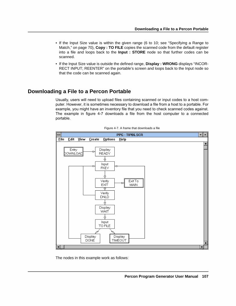
Downloading a File to a Percon Portable
Percon Program Generator User Manual 107
DRAFT—12/16/96 1:57pmD:\DOCS\PPG\CH4.FMD
• If the Input Size value is within the given range (6 to 10; see “Specifying a Range toMatch,” on page 70), Copy : TO FILE copies the scanned code from the default registerinto a file and loops back to the Input : STORE node so that further codes can bescanned.
• If the Input Size value is outside the defined range, Display : WRONG displays “INCOR-RECT INPUT; REENTER” on the portable’s screen and loops back to the Input node sothat the code can be scanned again.
Downloading a File to a Percon PortableUsually, users will need to upload files containing scanned or input codes to a host com-puter. However, it is sometimes necessary to download a file from a host to a portable. Forexample, you might have an inventory file that you need to check scanned codes against.The example in figure 4-7 downloads a file from the host computer to a connectedportable.
The nodes in this example work as follows:
Figure 4-7. A frame that downloads a file

Chapter 4: Example Frames
108 Percon Program Generator User Manual
DRAFT—12/16/96 1:57pmD:\DOCS\PPG\CH4.FMD
• Display : READY instructs the user to press F3 to download a file or F4 to exit.
• Input : FKEY accepts function key input.
• Verify : EXIT checks to see if F4 was pressed and, if it was, exits the frame.
• Verify : DNLD checks to see if F3 was pressed and, if it was, continues to the Displaynode. If F3 was not pressed, the program loops back to the Input node and waits for fur-ther input.
• Display : WAIT displays “Downloading, Please Wait” on the portable’s screen.
• Input : TO FILE starts downloading the file. Options in its dialog box are set as shown infigure 4-8.
• If downloading is successful, Display : DONE displays “DOWNLOAD DONE; F3=MORE; F4=QUIT” on the portable’s screen. If downloading is unsuccessful, Display :TIMEOUT displays “TIMEOUT EXCEEDED; F3=TRY AGAIN; F4=QUIT” on the por-table’s screen. Both these Display nodes loop back to the Input : FKEY node, whichaccepts the user’s function key input.
To download a file to a portable, you must set options for the Input node as follows:
• The Serial and TimeOut radio buttons are both selected for the Input From option.TimeOut should link to a Display node that prompts the user to try again.
Figure 4-8. The Input: TO FILE dialog box

Finding the Number of Records in a File
Percon Program Generator User Manual 109
DRAFT—12/16/96 1:57pmD:\DOCS\PPG\CH4.FMD
• Destination is set to the desired file. You can choose to replace existing data or placenew data at the beginning or end of the file or at a given record number.
• The Echo to Display option is enabled so that the user can see the file going into theportable unit.
Finding the Number of Records in a FileThe easiest way to determine the number of records in a file is to use a Verify node withMatch set to a value you know is not in the file and the Store Index in Register check boxselected (with a register specified for storing the index value). Since it won’t find a match,the program will return the file size, storing it in the index register.
Another method copies a known value to the end of the file, uses a Verify node to locate it,and then subtracts 1 from the location index. This method is demonstrated in the examplein figure 4-9.
Figure 4-9. A frame that determines the number of records in a file

Chapter 4: Example Frames
110 Percon Program Generator User Manual
DRAFT—12/16/96 1:57pmD:\DOCS\PPG\CH4.FMD
The nodes in this example work as follows:
• Display : RECORDS= writes “RECORDS=” on the portable’s screen.
• Copy : END copies the constant value “end” to the end of the file being checked.
• Verify : END looks for the constant “end” in the file and stores the index value of thematching record in a register named INDEX.
• Math : INDEX-1 subtracts 1 from the index value.
• Modify : DEL END deletes the “end” record so that the constant doesn’t corrupt the file.
• Output : POSITION positions the cursor at column 8 in the first line, directly after“RECORDS=”.
• Output : TOTAL displays the index value at the cursor position on the portable screen.
• Input : TO EXIT waits for a function or data key to be pressed before returning to theMain frame.
Searching for a Partial MatchA Verify node will search a file for a record that matches a given value or text string, for ex-ample, the value 100. The program searches for full matches, however; records containing1000 or 1001, for example, would not be considered a match. You can search for partialmatches using a frame such as the one in figure 4-10. This example pulls one record at atime from the file and uses templates to check the section of the record that you are tryingto match.
Figure 4-10. A frame that searches for a partial match
Splitting Records into Two Files
Percon Program Generator User Manual 111
DRAFT—12/16/96 1:57pmD:\DOCS\PPG\CH4.FMD
The nodes in this example perform the following actions:
• Display : CHECKING prompts the user to wait while the check is going on. This is espe-cially important when working with large files that take a long time to check.
• Copy : END places the constant “end” at the end of the file being checked.
• Copy : INDEX=1 stores the constant 1 in a register named INDEX.
• Copy : RECORD copies the record at index position 1 into the default register.
• As each record is copied, Verify : END looks for the constant “end” in the register. When“end” is found, the program has searched through to the end of the file; the search is dis-continued, and “NO MATCH” is displayed on the portable’s screen. When the userpresses a function key, the program deletes the “end” record and returns to the Mainframe.
• If “end” is not found in the default register, the program assumes it is looking at a validrecord and (with Copy : PART) uses a template to copy the part of the record beingchecked into another register, named CHECK.
• Verify : MATCH then checks to see if the contents of the CHECK register match thecontents of the INDEX register.
• If the register contents match, Modify : DEL END deletes the “end” record, and the pro-gram returns to the main frame.
• If there is no match, Math : INDEX+1 increases the index position number by 1 so thatthe program will look at the next register in the file.
This loop is continued until the program finds a match or reaches the “end” flag.
To speed up the search, you could split the records into two files and search for a com-plete match instead of a partial match (see the next section).
Splitting Records into Two FilesWhen verifying only a part of a record, you can accelerate the process by splitting therecord into two different files and referencing each file’s index position. For example, if youhad a file with the following records showing item numbers and descriptions:
item1, desc1item2, desc2item3, desc3
you could divide it into two files as follows:
File1 File2item1 desc1item2 desc2item3 desc3

Chapter 4: Example Frames
112 Percon Program Generator User Manual
DRAFT—12/16/96 1:57pmD:\DOCS\PPG\CH4.FMD
Instead of searching through both item numbers and descriptions, your program couldsearch through File1, which contains item numbers only. When the item number is found,you can use the same index number to find the matching description in File2.
Figure 4-11 shows a sample program frame used to divide a data file into two files. (Use adifferent program first to load the file into the portable.)
The nodes in this example work as follows:
• Display : WAIT instructs the user to wait while the Percon portable completes thisprocess.
• Copy : END places the constant “end” at the end of the file to mark the last record.
• Copy : 1ST REC copies the first record in the file into the default register.
• Verify : END checks to see whether the default register contains the constant “end”.
• If the default register doesn’t contain “end”, Copy : 1ST FIL copies the first part of therecord to a different file (1ST FILE), and Copy : 2ND FIL copies the other part of therecord into another file (2ND FILE).
• Modify : DEL 1ST deletes the first record in the original (default) file; what was the sec-ond record in the file is now the first.
• The program loops back to Copy : 1ST FIL, and the next record is split into two differentfiles.
Figure 4-11. A frame that divides records into two files

Referencing Two Different Files
Percon Program Generator User Manual 113
DRAFT—12/16/96 1:57pmD:\DOCS\PPG\CH4.FMD
• This loop continues until the program reaches the final record (containing “end”). At thatpoint, the program knows it has reached the end of the file, and Modify : DEL TEMPdeletes the default file to make sure it’s clear for the next time it’s used. The programthen returns to the Main frame.
Referencing Two Different FilesThe example in figure 4-12 uses two data files: one that contains item numbers and onethat contains item descriptions. Records in both are sorted identically. By referencing datain both files, this example displays the description of an item whose number is entered bythe user.
The nodes in this example work as follows:
• Display : SCAN prompts the user to enter an item number or press F4 to quit.
• Input : ITEM stores the input entry in the default register.
• Verify : F4 checks to see whether the user pressed F4. If so, the program returns to themain frame.
• Verify : IN FILE checks the contents of the default register against the file with the itemsin it. Figure 4-13 shows the settings in the dialog box for the node.
Figure 4-12. A frame that references two files

Chapter 4: Example Frames
114 Percon Program Generator User Manual
DRAFT—12/16/96 1:57pmD:\DOCS\PPG\CH4.FMD
• If there is no match, Display : NO MATCH instructs the user to enter the item numberagain and loops back to Input : ITEM.
• If there is a match, the indexed position is put into a second register, and Copy : INDEXcopies the record at that indexed position from the description file into the default regis-ter (see figure 4-14).
Figure 4-13. The Verify: IN FILE dialog box
Figure 4-14. The Copy : INDEX dialog box

Reviewing a File
Percon Program Generator User Manual 115
DRAFT—12/16/96 1:57pmD:\DOCS\PPG\CH4.FMD
• Output : POSITION positions the cursor on the portable screen.
• Output : TO DISP writes the item description at the cursor position.
• The program returns to Display : SCAN, prompting the user to enter an item numberagain.
Reviewing a FileThe example in figure 4-15 lets the user review the contents of a file, one record at a time.
The nodes in this example work as follows:
• Copy : END copies the constant “end” to the end of the default file to mark the lastrecord.
• Copy : INDEX=1 copies the number 1 into a register named INDEX. This register willdetermine which record is displayed.
• Verify : END looks at the record at the position specified in the INDEX register. If therecord contains “end”, this is the last record in the file, and the program deletes the “end”record and exits to the main frame. If it does not find “end”, the program continues to theOutput node.
Figure 4-15. A frame that reviews a file

Chapter 4: Example Frames
116 Percon Program Generator User Manual
DRAFT—12/16/96 1:57pmD:\DOCS\PPG\CH4.FMD
• Output : INDEXED displays the contents of the record at the position specified in theINDEX register on the portable’s screen. Figure 4-16 shows the settings in the dialogbox for the node.
• Math : INDEX+1 increments the value in the INDEX register by 1 so that the next recordin the file will be displayed.
• Input : NEXT keeps the record contents displayed until the user presses a key. The pro-gram then loops back to Verify : END so that the next record can be displayed.
The loop continues until the “end” record is reached, at which point the program deletesthe “end” record and exits the frame.
The file is displayed one record at a time on the screen. Each time the user presses a key,the next record is displayed on the last line, and the previous line moves up. The user canscroll the screen up to see previous entries in the file.
A variation of this example gives the user the ability to search through records in both di-rections: First, find the end of the file (see “Finding the Number of Records in a File,” onpage 109). Next, output the first record and give the option to see the next or the previousrecord. Then, increment or decrement the counter and verify that the range is between 1and the end-of-the-file value.
Figure 4-16. The Output : INDEXED dialog box

Sounding a Beep
Percon Program Generator User Manual 117
DRAFT—12/16/96 1:57pmD:\DOCS\PPG\CH4.FMD
Sounding a BeepTo sound a beep on a portable, use an Output node with the Source option set to Con-stant and Destination set to System. In the input box for the constant, enter one of thefollowing codes:
.+ (sounds a high beep)
.- (sounds a low beep)
You can enter more than one code, for multiple tones. For example, .+.-.+ sounds a highbeep followed by a low beep followed by another high beep.
Converting the PT 2000 into a WedgeTo use the PT 2000 as a wedge between a computer and its keyboard, connect thePT 2000 to the cable (part number 00-884-20). Then connect the other end of the cable tothe wedge cable (part number 00-001-00 or 00-061-00), set up between the keyboard andthe computer. Use a program frame similar to that shown in figure 4-17 to display scanneddata both on the PT 2000 and on the computer screen.
The nodes in this example work as follows:
• Output : TO OFF sets the automatic timeout setting to 99 minutes. This keeps thePT 2000 from turning off after 10 minutes.
Figure 4-17. A frame that outputs data to a PC screen

Chapter 4: Example Frames
118 Percon Program Generator User Manual
DRAFT—12/16/96 1:57pmD:\DOCS\PPG\CH4.FMD
• Display : SCAN prompts the user to scan a bar code or press F4 to exit.
• Input : DATA accepts scanned data and stores it in the default register.
• Verify : EXIT checks to see whether the user pressed F4. If so, Output : TO ON resetsthe automatic timeout setting before the program returns to the Frames level.
• Output : TO PC displays the scanned data (stored in the default register) on the con-nected PC screen. If output fails, Menu : FAILED announces this, and the program exitsto the Frames level.
• Output : SCAN POS positions the cursor on the PT 2000 screen, and Output : SCANdisplays the scanned data at the cursor.
The PT 2000 can be powered and charged from the keyboard.
Padding a Number with Leading ZerosMany database programs use fixed-length fields, which means that values stored in themmust be a given number of characters long. Values with fewer than the required characterscan be “padded” with zeros at the beginning; the value 12, for example, would appear as0012. The program frame shown in figure 4-18 uses a combination of Modify nodes, Copynodes, and two templates to pad a number with leading zeros.
The nodes in this example work as follows:
• Copy : QTY copies the quantity value in the default register into the INPUT SIZEregister.
Figure 4-18. A frame that pads a number with leading zeros

Padding a Number with Leading Zeros
Percon Program Generator User Manual 119
DRAFT—12/16/96 1:57pmD:\DOCS\PPG\CH4.FMD
• Modify : REVERSE1 reverses the order of digits in the INPUT SIZE register.
• Copy : ZEROS copies six zeros to the end of the value in the INPUT SIZE register.
• Copy : 1ST SIX copies the first six digits in the INPUT SIZE register back into the Quan-tity field of the default register. Any zeros beyond the sixth digit are dropped.
• Modify : REVERSE2 reverses the six characters in the default register, returning theoriginal input to the correct order with leading zeros.
This technique can be used with any fixed length by simply changing the fixed length ofthe second template and providing enough zeros in the Copy node.


Percon Program Generator User Manual 121
DRAFT—12/16/96 1:57pmD:\DOCS\PPG\APPA.FMD
Appendix AError Messages
This appendix lists error messages that you might come across in the Percon ProgramGenerator. Following each error message is a possible solution and, where applicable, areference to the section of this manual in which you can find more information about solv-ing the problem. If you continue to have trouble with your program, you can call Percon fortechnical assistance (see “Technical Support,” on page 4).
Column must be between 0-15.
You entered an invalid column number in the Input Echo subdialog box of the Input nodedialog box. You must specify a column position from 0 to 15.
See “Echoing Input,” on page 62.
Double quote.
You specified a register, file, or field name that contains one or more double quotationmarks ("), which are not acceptable. Enter the name again without the quotation marks.
Empty string.
You selected Accept in a dialog box without specifying a required register, file, or fieldname. Return to the dialog box and fill in any empty input boxes.
No more than 8 sections in link.
You created a link that had more than the limit of eight sections or seven joints. You needto modify the link.
See “Creating and Using Links,” beginning on page 56.
Row must be between 0-3.
You entered in invalid row number in the Input Echo subdialog box of the Input Node dialogbox. You must specify a row number from 0 to 3.
See “Echoing Input,” on page 62.

Appendix A: Error Messages
122 Percon Program Generator User Manual
DRAFT—12/16/96 1:57pmD:\DOCS\PPG\APPA.FMD
Syntax error.
PPG generated source code that is not recognizable by the portable. Under normal cir-cumstances, this message should never appear. If you encounter it, however, save yourfile and send it to Percon for debugging.
Timeout exceeded.
When downloading a program or data file into the portable, PPG did not receive acknowl-edgment from the portable within a specified number of seconds. Make sure the portableis securely connected to the PC and that the appropriate COM port is selected. Try reset-ting the portable (eject and replace the battery while pressing Shift+Enter). You may needto prepare the portable for downloading first by scanning the following code:
*/.*See “If You Have Problems,” on page 93.
Undefined link.
A node in your program flow chart is missing a required link. This error occurs most oftenfor Verify, Math, and Output nodes. These nodes require two links, even if both go to thesame node. Check all nodes of these types and make sure that both settings for Link Onlist nodes. If either the Success or Failure option is set to None, you need to create a sec-ond link, even if it duplicates the first.
See “Creating and Using Links,” beginning on page 56; “Verify Nodes,” beginning on page67; “Math Nodes,” beginning on page 63; “Output Nodes,” beginning on page 66; and thetip on page 25.

Percon Program Generator User Manual 123
DRAFT—12/16/96 1:57pmD:\DOCS\PPG\APPB.FMD
Appendix BWarranty Information
For a period of up to 90 days from the date of shipment from Percon, Percon warrants themagnetic disk on which the Percon Program Generator is stored to be free from defects inmaterials and faulty workmanship. If you encounter a defect on the disk within this period,call the Percon Technical Support group at 503-344-1189 for instructions and a Return Au-thorization number for returning the disk to Percon. Percon will replace the faulty disk atno extra charge. After the 90-day warranty period, there is a nominal charge for diskreplacement.
No other express warranty is given. The replacement of a product is your exclusive rem-edy. Any other implied warranty of merchantability or fitness is limited to the duration ofthis written warranty. Some states, provinces, or countries don't allow limitations on howlong an implied warranty lasts, so the above limitation may not apply to you.
In no event shall Percon be liable for consequential damages. Some states, provinces, orcountries do not allow the exclusion or limitation of incidental or consequential damages,so the above limitations or exclusions may not apply to you.
This warranty gives you specific legal rights, and you may also have other rights that varyfrom state to state, province to province, or country to country.
Products are sold on the basis of specifications applicable at the time of manufacture.Percon shall have no obligation to modify or update products once sold.

124 Percon Program Generator User Manual
DRAFT—12/16/96 1:57pmD:\DOCS\PPG\APPC.FMD
Appendix CASCII Table
Hex ASCII Hex ASCII Hex ASCII Hex ASCII
00 NUL 20 SP 40 @ 60 `
01 SOH 21 ! 41 A 61 a02 STX 22 " 42 B 62 b03 ETX 23 # 43 C 63 c
04 EOT 24 $ 44 D 64 d05 ENQ 25 % 45 E 65 e06 ACK 26 & 46 F 66 f
07 Bell 27 ' 47 G 67 g08 BS 28 ( 48 H 68 h09 TAB 29 ) 49 I 69 i
0A LF 2A * 4A J 6A j0B VT 2B + 4B K 6B k0C FF 2C , 4C L 6C l
0D CR 2D - 4D M 6D m0E SO 2E . 4E N 6E n0F SI 2F / 4F O 6F o
10 DLE 30 0 50 P 70 p11 DC1 31 1 51 Q 71 q12 DC2 32 2 52 R 72 r
13 DC3 33 3 53 S 73 s14 DC4 34 4 54 T 74 t15 NAK 35 5 55 U 75 u
16 SYN 36 6 56 V 76 v17 ETB 37 7 57 W 77 w18 CAN 38 8 58 X 78 x
19 EM 39 9 59 Y 79 y1A SUB 3A : 5A Z 7A z1B ESC 3B ; 5B [ 7B {
1C FS 3C < 5C \ 7C |1D GS 3D = 5D ] 7D }
1E RS 3E > 5E ^ 7E ~1F US 3F ? 5F _ 7F DEL

Percon Program Generator User Manual 125
DRAFT—12/16/96 1:57pmD:\DOCS\PPG\APPD.FMD
Appendix DThe PPG Library
Percon offers a library of several sample PPG program source files. This library, which isavailable from your PPG dealer (ask for part number 00-734-20), provides samples of filemanipulation, templates, and nodes. Several working programs are included, althoughmany of them are only examples and do not provide any functional value. This appendixbriefly describes each file.
ASHOST.SCRA data-collection program that allows a remote system to call up the portable via modemand receive the data.
AUTO.BATA batch file that uses the SAMPLE2.SCR program and automatically pulls files from thecollect mode.
BASIC.SCRA program with options for Menu, Upload, and Erase nodes completed. The Collect nodeis left empty for the user to set up.
CASHREG.SCRA program that does all the basic things a cash register would do, including figure totalswith taxes, figure change, and print a receipt.
CLOCK.SCRA program that displays time and date. Formats are selectable, and an alarm capability isavailable.
COLLECT.SCRThe collect portion of the sample program that comes with each portable.

Appendix D: The PPG Library
126 Percon Program Generator User Manual
DRAFT—12/16/96 1:57pmD:\DOCS\PPG\APPD.FMD
COLLTIME.SCRA program that stamps all item entries with the date and time. Output format isdate,time,item.
COMPILE.SCRA collect-only program that counts the number of duplicate entries in a file. Output formatis item,repeats.
CONFIG.SCRA program that allows the user to scroll through and change system parameters from a listthat is loaded into the portable.
FIELDS.SCRA short program that demonstrates template use by combining two inputs with a commadelimiter.
FIELDS1.SCRA template example where the first two characters are stripped out of the register.
HANGMAN.SCRA program that uses the classic word game as an excellent example of complex file ma-nipulation. A word of up to nine characters is entered by a user. A second user thenguesses the word. Each correct guess is filled into the appropriate blank, and each incor-rect guess is displayed on the screen as “Hangman” is spelled out.
HOSPITAL.SCRA program designed to help nurses track patient medications and used items. It also has areminder feature and a way to review each patient’s file.
INSPECT.SCRA program that prompts the user with questions about a scanned item and records a passor fail condition with comments.
ITQU.SCRThe other portion of the standard sample program that comes with each portable. Itemand quantity collection are featured.
LIBRARY.SCRAn application to track checked in, checked out, and late books in a school library.

The PPG Library
Percon Program Generator User Manual 127
DRAFT—12/16/96 1:57pmD:\DOCS\PPG\APPD.FMD
MATH.SCRAn example of the math node. The register is multiplied by 3.
METO5000.SCRAn example of running a serial printer with the portable.
MODEM.SCRA complete example of a modem communications program designed to transmit and re-ceive files.
MODIFY.SCRAn example of the Modify node that options for all modify functions.
MONEY.SCRA program that keeps a running total on an item. A pick list file is downloaded into the por-table, and as the items are matched, the user has the option to add or subtract a quantityfrom the total.
MULTIPLE.SCRA multiple-option program that includes a Collect node with a compile option; an item/quantity option; a pick list; a calculator; and a clock option.
MULTPLE2.SCRA large program (342 nodes, with 8 separate programs) that has the same options asMULTIPLE.SCR plus a modem communications program, the hangman game, and a timetracker.
PICKLIST.SCRA program in which, as items are matched, they are erased from a downloaded pick listand moved to another file for uploading.
RANGE.SCRA sample of a range test, in which high and low numbers are entered and followed by atest number. In or out of range is then displayed.
TRACKER.SCRA sample of a minutes counter. A pick list is downloaded, and when a function is chosen,time (in minutes) is counted until the function key is selected. Total time is accumulated foreach function.

Appendix D: The PPG Library
128 Percon Program Generator User Manual
DRAFT—12/16/96 1:57pmD:\DOCS\PPG\APPD.FMD
TRACKER2.SCRA sample of a different approach to tracking time. As each function is scanned or typed in,the time is reset to zero. The clock updates every second, and the total time is then copiedto the file in regular clock format.
UPLOAD.SCRA sample data-collection program that transmits data via a modem using Procomm Plus inhost mode.
UPPRPLUS.SCRA sample data-collection program that transmits data to a host via a modem usingProcomm Plus in host mode.

Percon Program Generator User Manual 129
DRAFT—12/16/96 1:57pmD:\DOCS\PPG\APPE.FMD
Appendix EUseful Bar Codes
Reset Factory Defaults
*$+S-D2C8EE*
File Dump
*$$*
Program Mode
*/.*
Set Date
*%.*

Appendix E: Useful Bar Codes
130 Percon Program Generator User Manual
DRAFT—12/16/96 1:57pmD:\DOCS\PPG\APPE.FMD
Set Time
*%-*
<CR> Only Protocol
*$+$-CA00EE*
ACK/NAK Protocol
*$+$-CA01EE*
Xmodem Protocol
*$+$-CA02EE*

131
DRAFT—12/16/96 1:57pmD:\DOCS\PPG\GLOSSARY.FMD
*GLOSSARY*GLOSSARY*GLOSSARY*GLOSSARY*GLOSSARY*GLOSSARY*GLOSSARY*GLOSSARY*GLOSSARYGlossary
This section contains definitions for important terms used in this manual. You should be fa-miliar with these terms before attempting to use Percon Program Generator (PPG) to cre-ate your own programs. Italicized words in definitions are defined in this glossary.
breakpointIf there are certain areas of your program that you want to focus in on when using the em-ulator, you can set a breakpoint at one or more nodes. When you execute the program(with the Run command), the emulator will stop execution wherever there is a breakpoint.You can then use Run or Step to resume execution.
Call nodeA Call node executes a branch to a subroutine.
columnsThe display screen of your Percon portable is divided vertically into sixteen columns, num-bered 0 through 15.
Copy nodeA Copy node is used to transfer information from one file or register to another file orregister.
data collectionData collection is the process of gathering information by scanning bar codes or usingdata keys to enter values into a portable.

Glossary
132 Percon Program Generator User Manual
DRAFT—12/16/96 1:57pmD:\DOCS\PPG\GLOSSARY.FMD
Display nodeA Display node is used to define messages to appear on a portable’s screen.
DOSDOS is the Disk Operating System used by the PC. It is the foundation on which Windowsand other programs are run.
emulatorThe emulator is a utility that models a portable for the testing of program flow charts.
fieldA field is a place in a register for the entry of or access to a specified type of data. Fieldsand their locations in a register are defined by templates.
fileA file is a storage location for data. Flow charts you create in PPG are stored in files onyour PC. Portables use a different type of file for storing collected or downloaded data (seeportable file).
framesFrames are the objects you use to create the general flow chart of your data-collectiontasks. Each frame in a program flow chart represents a major function or option. Typically,a program's frames include a Main Menu frame and a frame for each option on the menu.Links connect the frame in a way that indicates program flow.
Frames levelThe Frames level of a program flow chart shows the main functions of the program. Detailsof each function are given in a Nodes level for each frame.
indexAn index is a number used to access a single record in a file.
inputInput is the information gathered during data collection or the action of gathering theinformation.
Input nodeAn Input node designates what type of portable input is acceptable and where the inputwill be stored.

Glossary
Percon Program Generator User Manual 133
DRAFT—12/16/96 1:57pmD:\DOCS\PPG\GLOSSARY.FMD
jointed linkA jointed link is a link that has two or more segments intersecting at right angles.
linkA link connects two frames or nodes with an arrow directing the program to the next step.A link pointing to a frame or node shows how it is accessed. A link pointing away from aframe or node shows where the program goes next.
Math nodeA Math node performs mathematical operations on given data.
Menu nodeA Menu node presents a menu of options on the portable’s screen and specifies what ac-tions will occur when the user presses function keys associated with those options.
Modify nodeA Modify node changes given data.
nodeA node is a box in the Nodes level of a program flow chart that represents one step in theprogram. There are different types of nodes for each kind of action that can be performedby the program. Detailed instructions for the action are specified by settings in a dialog boxassociated with the node. A connected set of nodes makes up one frame of a programflow chart.
Nodes levelThe Nodes level gives step-by-step details for a particular frame of a program flow chart.The details are given in various types of nodes. Each frame of a flow chart has its own setof nodes at the Nodes level.
objectAn object is the generic term for a frame, node, or link.
Output nodeAn Output node is used to transfer data to a portable’s display or to the host computer.

Glossary
134 Percon Program Generator User Manual
DRAFT—12/16/96 1:57pmD:\DOCS\PPG\GLOSSARY.FMD
portable fileData that has been either input via a portable’s wand or data keys or downloaded from aPC file through the serial port is saved in a portable file. Each entry in the portable file iscalled a record, and the records in each portable file are numbered, starting with 1 for thefirst record.
program source fileProgram flow charts created with PPG are stored in DOS data files called program sourcefiles. A program source file must be compiled (using PPG) before it can be loaded into aportable.
record A record is a set of related data fields stored as a single line in a file.
registerA register is a temporary holding place for up to 128 characters of data. When you scan abar code with a portable, the code is stored in a register until it is verified and copied into afile for safekeeping. The contents of the register are overwritten each time you scan acode.
rowsThe display screen of your Percon portable is divided horizontally into four rows, num-bered 0 through 3.
subroutineA subroutine contains nodes that execute program steps, very much like a frame. The dif-ference is that a subroutine sits off to the side of a flow chart instead of being connected toother objects. It contains functions that can be referenced within any of the program’sframes with a Call node.
templateA template is a structure that you can define and impose on data. It lets you alter the wayin which collected data is stored. The most common use of a template is to take data fromtwo or more registers and tie them together in a single register.
Verify nodeA Verify node checks data against specified requirements.

135
DRAFT—12/16/96D:\DOCS\PPG\PPG.IX
*INDEX*INDEX*INDEX*INDEX*INDEX*INDEX*INDEX*INDEX*INDEX*INDEX*INDEX*INDEX*INDEX*INDEXIndex
8th bit, clearing from data 66
Aactivity, tracing during emulation 91adjusting
frames 18, 54jointed links 19links 19, 45, 57
applicationsMACTFER 98PDPROG 85PDTFER 98PROG 93PTFER 17, 42, 94updtfer 99
arrows see linksASCII characters 124Auto Off setting 103axes, grid settings for 82
Bbacking up program source files 2bar codes 129bar code types, specifying 83baud rate 96beeps 30
setting tone of 68, 117
bitsdata 96eighth, clearing from data 66stop 96
box size for frames and nodes 82Break command (Emulation window) 88, 89, 90breakpoints 89, 131buttons
Connect (in PTFER) 94, 97radio 27
Ccalendar 68Call nodes 56, 58, 131characters
ASCII 124number of (in registers) 62
clearingdisplay screen 62eighth bit from data 66
clock 68, 102bar code for 129
closing PPG 7Codabar 83Code 128 83Code 39 83commands, output 68

Index
136 Percon Program Generator User Manual
DRAFT—12/16/96D:\DOCS\PPG\PPG.IX
communications settingsdefaults, resetting 42, 96
bar code for 129for MACTFER 98for PTFER 96for updtfer 100Port options for 96
compiler window 15, 92computer requirements for PPG 2computer systems
Macintosh 8, 93UNIX 8, 93
Connect button (in PTFER) 94, 97Connect command (in PTFER) 94, 96, 97constants in math operations 64Control-menu box, location of 6conventions, typographic 3Copy command 79
in MACTFER window 99copying
data to a portable file 31input to a file 59objects 79
Copy nodes 59, 131Copy : To File 31
Create menuFrame 54Link 56Lock 54, 56, 58for Nodes level 57Subroutine 55Unlock 54, 56, 58
creatingframes 18, 53jointed links 19, 56links 19, 56
from Output nodes 33nodes 24, 58program source files 86registers 28subroutines 55
cursor position on display screen 62, 68Cut command 79
compared with Delete 80cutting objects 79
Ddata
breaking into fields in a register 78controlling flow of 71copying to a file 59destination for 63flow, controlling 71input
allowing from portable 61in Emulation window 89
modifying 65moving between registers and files 59reversing order of 66searching for and replacing 66specifying input method for 60storing
in fields 63in files 63in registers 63
transferring 8, 93from DOS 98from Microsoft Windows 94
translating 8, 75uploading 16, 42verifying 70
data bits 96data collection, defined 131data flow, controlling 71data type, verifying 70date 68, 102
bar code for 129default communications settings 96, 98, 100
resetting 42, 96bar code for 129
defining fields 76Delete command 80
compared with Cut command 80deleting
contents of registers, fields, or files 66data 66frames 18, 80links 19, 44, 57nodes 80objects 80registers 28

Index
Percon Program Generator User Manual 137
DRAFT—12/16/96D:\DOCS\PPG\PPG.IX
directory, PPG31 6display (portable screen)
clearing 62, 68echoing to 61, 62outputting commands to 68outputting data to 67position of cursor on 62, 68showing menus on 64showing text on 60size of 64, 65
displaying error messages 30Display nodes 60, 132
Display : Enter Item 26Display : Error Text 30Display : Successful 35
DOS 132transferring data from 98version 2, 4
downloading programs 7, 15, 40, 53, 92Download Program command 7, 15, 40, 53, 85,
92drag-and-drop 7
Eechoing data input 61, 62editing programs 79Edit menu 79, 80
Copy 79in MACTFER window 99
Cut 79Delete 80keyboard shortcuts for 79Paste 79Rename 54, 56, 58, 79, 80
eighth bit, clearing from data 66emulating programs 7, 37–40, 87–91
setting breakpoints 89watching registers 90
Emulation command 53, 87Emulation window 87
Break command 88, 89, 90ENTER button in 89inputting data in 89menu bar commands 88–89
Options menu 88PocketReader 88PT 2000 88Trace 88, 91Watch 88, 90, 91
Reset command 88Run command 88, 89Serial command 89Shift button in 89Step command 88, 89Stop command 89Timeout command 89Wand command 89
enlarging the PPG window 7ENTER button in Emulation window 89Entry nodes 12, 57equipment requirements 2erasing
contents of registers, fields, or files 66error messages 121–122
displaying on portable screen 30Exit command 92, 94exiting
online help 50PPG 7
Exit nodes 12, 57
FF1, getting online help with 50fields 43, 71, 73, 132
creating for templates 46creating from data in a register 78defining 76erasing contents of 66storing data in 63
file dump, bar code for 129File Manager, starting PPG from 7File menu 84
Download Program 7, 15, 40, 53, 85, 92Exit 92, 94New 52, 86Open 85, 93
in Percon Portable Programmer window 85

Index
138 Percon Program Generator User Manual
DRAFT—12/16/96D:\DOCS\PPG\PPG.IX
Print 87Receive
in MACTFER window 99in PTFER 95
Save 86Save As 86Send
in MACTFER window 99in PTFER 95
file names 31files 71, 132
downloading to a portable 93, 107erasing contents of 66math operations on 64number of records in 109portable 73, 134
copying data to 31erasing 66moving data to and from 59naming 31
program source 84, 134creating 86directory for 86downloading 7, 15, 40, 53, 92opening 85printing 87samples 8, 10saving 86starting PPG with 7testing 7, 37–40, 87–91
referencing multiple 113reviewing contents of 115searching for a partial match 110splitting into two 111storing data in 63
flow charts see programsflow of data 71Font command 82fonts, changing 82Frame command 54frames 132
adjusting 18, 54calling subroutines from 56changing fonts in 82copying 79creating 18, 53cutting 79deleting 18, 80
examples 101moving 18, 54, 79naming 19, 54, 80pasting 79renaming 19, 54, 80size 82starting 84
Frames command 52Frames level 52, 132function keys
allowing input from 61, 65assigning to menu items 65
Ggenerating programs 7, 52glossary 131–134Grid command 82
Hhelp, online 50
exiting from 50hot keys for 50
Help menu 50How to Use Help 50
horizontal axis, setting snap grid for 82hot keys for online help 50How to Use Help option 50
II 2/5 83icons 6
PPG 6PROG 6, 93PTFER 6
index 132input 132
controlling flow of 71copying to a file 59destination for 63echoing 61, 62modifying 65size, verifying 105

Index
Percon Program Generator User Manual 139
DRAFT—12/16/96D:\DOCS\PPG\PPG.IX
storingin fields 63in files 63in registers 63
verifying 69see also data
Input nodes 60, 132Input : Item 26Input : Timeout Display 36linking to other nodes or frames 61
inputting data in Emulation window 89installing PPG 5
Jjointed links 133
adjusting 19creating 19, 56
Kkeyboard shortcuts for Edit menu commands 79keyboard wedge 67
Lleaving PPG 7levels of programs 52license agreement 2Link command 56links 56, 133
adjusting 19, 45, 57creating 19, 56
from Output nodes 33deleting 19, 44, 57grid settings for 83jointed 133
adjusting 19creating 19, 56
overlapping 57loading PPG 6
from File Manager 7Lock command 21, 45, 54, 56, 58lowercase, changing to uppercase 66
MMacintosh computers 8, 93
transferring data from 98MACTFER 93, 98
window for 99manual, typographic conventions in 3Math nodes 63, 133
linking to other nodes or frames 64math operations 64
storing results of 64Maximize button, location of 6maximizing the PPG window 7memory requirements 2Menu nodes 64, 133
linking to other nodes or frames 65Menu : Confirmation 33Menu : Error Text 35
menusassigning function keys to 65Create, for Nodes level 57Edit 79File 84Help 50see also Create menu, Options menu, and
View menumessages, error 121–122
displaying on portable screen 30Microsoft Windows
Control-menu box 6drag-and-drop 7Maximize button 6Minimize button 6mode 2PPG window 6Program Item Properties window 97Program Manager 6starting PPG from File Manager 7transferring data from 94using 3version 2, 4
Minimize button, location of 6minimizing the PPG window 7modifying input 65modifying programs 79Modify nodes 65, 133
Modify : Erase File 36

Index
140 Percon Program Generator User Manual
DRAFT—12/16/96D:\DOCS\PPG\PPG.IX
mouseselecting two or more objects with 79
mouse, using 51moving
frames 18, 54links 19, 57nodes 58objects 79subroutines 55
Nnaming
files 31frames 19, 54, 80nodes 80subroutines 56
New command 86New command (in File menu) 52nodes 57–71, 133
Call 56, 58, 131changing fonts in 82Copy 59, 131
Copy : To File 31copying 79creating 24, 58
for templates 44cutting 79deleting 80Display 60, 132
Display : Enter Item 26Display : Error Text 30Display : Successful 35
double-line borders on 12Entry 12, 57Exit 12, 57Input 60, 132
Input : Item 26Input : Timeout Display 36linking to other nodes or frames 61
Math 63, 133linking to other nodes or frames 64
Menu 64, 133linking to other nodes or frames 65Menu : Confirmation 33Menu : Error Text 35
Modify 65, 133Modify : Erase File 36
moving 58, 79naming 80Output 67, 133
linking to other nodes or frames 69Output : Error Beep 30, 34Output : to PC 34
pasting 79renaming 80setting options for 58size 82Verify 69, 134
linking to other nodes or frames 71Verify : Input 29
Nodes command 52, 57Nodes level 52, 133
Create menu for 57
Oobjects 133
copying 79cutting 79deleting 80pasting 79selecting two or more 79
online help 50exiting from 50hot keys for 50
Open command 85, 93in Percon Portable Programmer window 85
opening program source files 85operating system
outputting commands to 68outputting data to 67
operations, math 64storing results of 64
Options menuin Emulation window
PocketReader 88PT 2000 88Trace 88, 89, 91Watch 88, 90, 91
Font 82Grid 82

Index
Percon Program Generator User Manual 141
DRAFT—12/16/96D:\DOCS\PPG\PPG.IX
in PTFERConnect 94, 96, 97Settings 94, 95, 96
Set Bar Codes 53, 83Set Start 54, 84
output commands 68Output nodes 67, 133
creating links from 33linking to other nodes or frames 69Output : Error Beep 30, 34Output : to PC 34
outputting data 67overlapping links
deleting 57selecting 57
Ppadding values with zeros 118parity 96Paste command 79pasting objects 79PDPROG 85PDTFER 8, 93, 98Percon Portable Compiler window 15, 92Percon Portable Programmer window 15, 85, 92Percon portables see portablesPercon PPG31 program group 6Percon Program Generator (PPG)
about 1, 7equipment requirements 2exiting 7installing 5loading 6
from File Manager 7Microsoft Windows mode for 2program icons 6program source files
backing up 2samples 8, 10
program upgrades 2version 4
pick lists 8modifying 77
PocketReaderemulating 37, 88see also portables
PocketReader command 88pointers, mouse 51portable files 73, 134
copying data to 31erasing 66moving data to and from 59naming 31
portablesallowing data input from 61beeps 30
setting tone of 68, 117calendar 68clock 68default communications settings 42
bar code for 129downloading files to 107echoing input to screen 61, 62function keys
allowing input from 61, 65assigning to menu items 65
PocketReader, emulating 37, 88programming 7, 15PT 2000
emulating 88using as keyboard wedge 67
screenclearing 62, 68displaying menus on 64displaying text on 60echoing input to 61, 62outputting commands to 68outputting data to 67position of cursor on 62, 68size of 64, 65
SHIFT key on 61, 65transferring data to 8, 93uploading data from 8, 42, 93
Port options in Communications Settings dialog box 96
position of cursor on display screen 62, 68PPG
icon for 6see also Percon Program Generator
PPG31 directory 6PPG Trace window 91PPG Watch window 38
SetUp option 90

Index
142 Percon Program Generator User Manual
DRAFT—12/16/96D:\DOCS\PPG\PPG.IX
PPG window 6enlarging 7maximizing 7minimizing 7reducing to an icon 7zooming 81
Print command 87printing program source files 87PROG 93
icon for 6program emulation 7program group
Percon PPG31 6program icons 6
PPG 6PROG 6PTFER 6
Program Item Properties window (Microsoft Windows) 97
program level 52Program Manager (Microsoft Windows) 6programmer window 15, 92programming Percon portables 7, 15programs
downloading 7, 15, 40, 53, 92editing 79emulating 7, 37–40, 87–91generating 7, 52icons for 6MACTFER 93modifying 79PDTFER 8, 93PTFER 8, 17, 42, 93
command line settings for 97communications settings for 96window for 94
starting frame in 84testing 7, 37, 53
see also emulating programsupdtfer 93zooming in on 81
program source files 84, 134backing up 2creating new 86directory for 86downloading 7, 15, 40, 53, 92opening 85printing 87
samples 8, 10saving 86starting PPG with 7testing 7, 37–40, 87–91
program upgrades 2protocols, bar codes for 130PT 2000
emulating 37, 88using as keyboard wedge 67, 117see also portables
PT 2000 command 88PTFER 8, 17, 42, 93, 94
command line settings for 97communications settings for 96icon for 6window for 94
Rradio buttons 27Receive command
in MACTFER window 99in PTFER 95
records 43, 71, 134dividing into two files 111erasing 66number of in a file 109searching for a partial match 110
reducing the PPG window to an icon 7registers 28, 71, 72, 134
breaking into fields 78creating 28deleting 28displaying contents of 103erasing 66erasing contents of 66math operations on 64number of characters in 62setting destination for input 63storing data in 63watching during emulation 90
registration card 2Rename command 54, 56, 58, 79, 80renaming
frames 19, 54, 80nodes 80subroutines 56

Index
Percon Program Generator User Manual 143
DRAFT—12/16/96D:\DOCS\PPG\PPG.IX
replacing data 66partial matches 110
repositioning see movingrequired equipment 2Reset command (Emulation window) 88resetting default communications settings 42, 96
bar code for 129reversing order of data 66Run command (Emulation window) 88, 89
SSAMPLE.SCR 8SAMPLE2.SCR 8SAMPLE3.SCR 8sample program source files 8, 10
ordering 8Save As command 86Save command 86saving program source files 86scanned data, translating 8scanner, allowing input from 61screen
clearing 62, 68displaying menus on 64displaying text on 60echoing input to 61, 62outputting commands to 68outputting data to 67position of cursor on 62, 68size of 64
searching for data 66partial matches 110
selecting objects 79Send command
in MACTFER window 99in PTFER 95
Serial command (Emulation window) 89serial interface, allowing input from 61serial port
changing 17connecting to the PTFER program 17outputting data to 67
Set Bar Codes command 53, 83Set Start command 54, 84
settings, communications 42Settings option (PTFER) 94, 95, 96SetUp option 90SHIFT+F1, getting online help with 50Shift button in Emulation window 89SHIFT key on portables 61, 65snap grid 82source files see program source filesstarting frame 84starting PPG 6
from File Manager 7Step command (Emulation window) 88, 89stop bits 96Stop command (Emulation window) 89Subroutine command 55subroutines 54, 134
calling 56, 58changing fonts in 82creating 55moving 55renaming 56
support, technical 4symbologies, specifying 83system (operating)
outputting commands to 68outputting data to 67
Ttechnical support 4templates 43–47, 71, 73, 74–77, 78, 134
about 43creating fields for 46creating nodes for 44
testing programs 7, 37, 53tracing activity 91see also emulating programs
text, selecting style and size of 82time 68, 102
bar code for 130timeout, setting 61Timeout command (Emulation window) 89Trace command 88, 89, 91Trace window 91tracing activity during emulation 91

Index
144 Percon Program Generator User Manual
DRAFT—12/16/96D:\DOCS\PPG\PPG.IX
transferring data 8, 93from a Macintosh 98from a UNIX workstation 99from Microsoft Windows 94from the DOS command line 98
translating data 8, 75troubleshooting 16, 41, 93typeface, selecting 82type of data, verifying 70typographic conventions 3
UUNIX workstations 8, 93
transferring data from 99Unlock command 21, 54, 56, 58UPC-EAN 83updtfer 93, 99upgrades, program 2uploading data 16, 42uppercase, changing to lowercase 66using Microsoft Windows 3
Vverifying
data 69, 70input size 105
Verify nodes 29, 69, 134linking to other nodes or frames 71Verify : Input 29
versionDOS 2, 4Microsoft Windows 2, 4PPG 4
vertical axis, setting snap grid for 82View menu
Emulation 53, 87Frames 52Nodes 52, 57Zoom In 81Zoom Out 81
Wwand, allowing input from 61Wand command (Emulation window) 89warranty information 123Watch command 88, 89, 90, 91watching registers during emulation 90Watch window 38wedge
keyboard 67using PT 2000 as 117
windowscompiler 15, 92Emulation see Emulation windowenlarging 7MACTFER 99maximizing 7minimizing 7Percon Portable Compiler 15, 92Percon Portable Programmer 15, 85, 92PPG Trace 91PPG Watch 38reducing 7
Windows see Microsoft Windows
Zzeros, padding values with 118Zoom In command 81Zoom Out command 81