The role of perched aquifers in hydrological connectivity and
los Alamos Environmental Restoration -· Recorda Pro~tt!!U!IIIina Facility
LA-UR-90-3230 ER Record 1.0.# 0007508
,·:
...
Perched Zone Monitoring Well Installation
by
: .~
W.O. Purtymun and A.K. Stoker
Environmental Protection Group (HSE-8)
'
Los Alamos National Laboratory
September, 1990
11111111111111111111111111111111111 10407

PERCHED ZONE MONITORING WELL INSTALLATION
I. INTRODUCTION
by W. D. Purtymun and A. K. Stoker
Environmental Protection Group (HSE-8)
Los Alamos National Laboratory September 1990
The Hazardous Waste Permit (Hazardous and Solid Waste Amendments, 1984) issued to the United States Department of Energy (owner) and the University of California (operator) contains several Special Conditions in Module VIII, Sec. C. The first condition relates to Perched Zone Monitoring. This condition required the installation of monitoring wells or borings in the principal canyons of the Pajarito Plateau as follows: Pueblo Canyon (one exploratory boring); Los Alamos Canyon (three monitoring wells near existing wells LA0-3, LA0-4.5, and LA0-5); Sandia Canyon (two monitoring wells near water supply wells PM-1 and PM-3); Mortandad Canyon (three monitoring wells near existing wells MC0-4, MC0-6, and MC0-7); Potrillo Canyon (one monitoring well near State Road 4); Fence Canyon (one monitoring well near State Road 4); and Water Canyon (three monitoring wells: one near State Road 4, one 1 mile west of State Road 4, and one 2 miles west of State Road 4). Water samples will be collected from the wells in September 1990 and analyzed for specific constituents in accordance with the timetable specified in the permit
These canyons were created by southeast-trending intermittent streams that have cut deeply into the surface of the plateau. 1be intermittent stream flow has eroded, transported, and deposited alluvium in the stream channel of these canyons. The origin of the drainage area of the canyons determines the general type of alluvium. Canyons that head on the flanks of the mountains west of the plateau contain mainly sands, gravels, cobbles, and boulders derived from dense, hard rock eroded from the flanks of the mountains. These canyons include three specified in the special condition: Pueblo, Los Alamos, and Water. Canyons that head on the plateau contain clays, silts, sands, and some gravels derived from the softer tuff that forms the plateau. 1bese canyons include four specified in the special condition: Sandia, Mortandad, Potrillo, and Fence.
The shallow aquifers in the alluvium of the canyons is in the sands, gravels, cobbles, and boulders of canyons heading on the mountains or in the reworlced and weathered clays, silts, sands, and gravels of canyons heading on the plateau.
1
W. D. Purtymun and A. K. Stoker PERCHED ZONE MONITORING WELL INSTALLA nON
Los Alamos National Laboratory September 1990
1be aquifers in the alluvium exist as a narrow ribbon of saturation along the canyon bottoms and are perched on the underlying silts and clays. The aquifers are of limited horizontal extent and are dependent on surface water for recharge. The spring snowmelt run-off causes water levels in the aquifer to rise and the aquifer to advance down the canyon. In early summer, the water levels typically decline and the aquifers retreat up the canyon. Summer run-off causes the water levels to rise and aquifers to advance down the canyon; the lack of run-off in the fall and winter causes the water level to decline and the aquifer to retreat up the canyon. 1bese same hydrologic effects take place in canyons that also receive treated industrial and/or sanitary effluents. Thus, dependent on the amount of recharge, the thickness of the saturated pan of the aquifer will vary and at times . may be dry. Tile water levels in an aquifer may vary by 10 or more feet in the course of a year.
II. WELL DRILLING AND COMPLETION
All of the wells or borings were drilled and completed using the same basic equipment and methods. 1be methods generally followed the recommendations of the Resource Conservation and Recovery Act (RCRA) Ground-Water Monitoring Technical Enforcement Guidance Document (TEGD) to the extent practicable and allowing for some modifications based on more than 40 years of experience with monitoring initiated by the U.S. Geological Survey. 1bese methods are described in this section and are applicable to all of the wells.
· Details of each individual well completion are provided in individual figures discussed later in this report. A pilot hole was drilled with either a standani continuous-flight auger (4.5 in. diameter) or cored with a hollow-stem auger (7.25-in. hole diameter). 1be depth to the base of the aquifer was detennined by the cuttings and drilling pressure or by direct inspection of the continuous ·core retrieved from the hole.
The characteristics of the alluvium (hole collapse) require construction of the well through a hollow-stem auger. Accordingly, the pilot hole provided a guide for reaming the hole using a larger diameter hollow-stem auger (6.25 in. i.d., 9.625 in. o.d., with a 10.375-in. o.d. bit). This bit was run in the pilot hole with a knockout plate, and the auger joints were equipped with 0-Ring seals. 1be hole was reamed below the base of the aquifer.
If water was encountered in the pilot hole, it was necessary to fill the 6.25-in. i.d. hollow-stem auger with water to a level equal to the top of the aquifer to keep sands and gravels from ruming into the hollow stem when the plate in the bit was knocked out The plate was knocked out and the auger raised 0.5 to 1.0 ft to anchor the casing on the bottom of the hole. The 2-in.-diameter casing was set through the hollow stem and rested on the plate. The lowest portion of the casing consisted of one or two 10-ft lengths of screen with a plug at the bottom. (In
2

W. D. Purtymun and A. K. Stoker
PERCHE_D ZONE MONITORING WELL INSTALLATION Los Alamos National Laboratory
September 1990
three wells, a 5-ft blank section was extended below the screen to provide for bailer descent to assist in collecting adequate sample volumes.)
1be annulus between the hollow-stem auger and casing screen was filled with the gravel pack (sand) in increments of 2 to 3 ft, at which time the auger was pulled up a corresponding amount Keeping the sand in the auger while raising the auger assured a continuous gravel pack between the borehole wall and the screen by preventing any formation material from caving in around the casing. Accordingly, this method is believed to be preferable to using a tremie after removal of the entire length of auger. 1be gravel pack was continued up to a point 2 to 3 ft above the top of the screened section. At this point, a seal of bentonite and/or cement was extended to the surface using the same method of emplacement through the auger to assure a continuous seal with no formation material collapsing in around the blank tubing.
At a depth of about 3 to 5 ft, the auger was removed from the hole. 1be upper part of the well was filled with cement and the wellhead security cap was set about 1.5 to 2ft into the cement. A brass cap was set in a 2-ft-square concrete pad poured around the wellhead security cap.
Ill. WELL CONSTRUCTION MATERIALS
1be materials used in well construction include the casing, the sand or gravel pack, the bentonite seal material, and cement. Also considered as part of the construction is the wellhead security cap that permits only authorized personnel to access the well for water-level measurements or sampling.
1be casing, screen, plugs, and caps were made of polyvinyl chloride (PVC), using flush-joint, internal, upset-threaded-type connections. The casing and screen were 2 in. i.d. (2.375 in. o.d.), in 5- or 10-ft lengths. 1be screen openings were 0.010 in. 1be casing, screen, plugs, and caps were manufactured by TIMCO Manufacturing, Inc. (85115th Street, Prairie Du Sac, Wisconsin 53578, phone 608-643-8534).
1be sand used for the gravel pack ·was sized from 0.010 to 0.020 in. and is compatible with the sereen openings in the casing of 0.010 in. Because of the nature of the aquifer material (very fine suspended particles), the smallest screen opening and appropriate size gravel pack were used. 1be sand used as a ~vel pack came in 50- or 100-lb bags. 'The 100-lb bag contained about 0.97 ft of pure Colorado silica sand. The sand was processed and marketed by Silica Sand, Inc. (P.O. Box 15615, Colorado Springs, Colorado 80935).
The bentonite was brand name Hole Plug, coarse-grade Wyoming bentonite, and was supplied in 50-lb bags, 0.69 ft3 per bag (dry), and was marlceted by Baroid Division (N.L. Petroleum Surveys, Inc., P.O. Box 1675, Houston, Texas).
3
W. D. Purtymun and A. K. Stoker
PERCHED ZONE MONITORING WELL INSTALLATION Los Alamos National Laboratory
September 1990
A premix cement (1 to 5) was used to seal part of the hole and to construct the wellhead and accompanying security cap. The cement mix came in 60-lb bags, about 0.5 ft3 per bag. The brand name of the mixture was Quikrete, marketed by the Quikrete Company, Atlanta, Georgia 30234.
Two types of well security caps were used in completion of the observation wells. The first type was a standard 8.625-in. o.d. steel casing set into the cement The top of the casing was secured with a hinged plate and hasp welded to the casing. The other type of well security was the 8.625-in. o.d. steel casing set into the cement, covered by a removable "mushroom" cap made from a 13-in. steel casing about 0.5 ft long with a steel plate welded to one end. 1be 13-in. casing with cap was set on the 8.625-in. casing. Slots cut through the side of the cap and the casing were aligned to receive a steel bar that secures the cap to the top of the casing. A hole through the bar allows a lock to secure the cap and prevent removal of the bar. Both types of caps are shown in Fig. 1.
IV. WELL DEVELOPMENT
Well development was carried out using several techniques in combination. However, none of the wells that have water in them has yet been able to meet the turbidity requirement of 5 nephelometric turbidity units. This was as expected, based on previous experience with the 25- to 30-year-old U.S. Geological Survey wells, which still yield samples with considerable turbidity. The turbidity results from the fine suspended clays and silts found in the aquifer. 'These clays and silts are derived from weathering of the ash matrix of the tuff. As a result, the smallest size screen generally available from commercial sources (0.010 in.), with matched sand size (0.010 to 0.020 in.), was used in completing all the new wells. The presence of these suspended sediments and the fluctuation of the thickness of the aquifer have hampered or prevented well development, even without suspended sediments entering the wells during bailing.
The wells were developed using a surge block, pumping, bailing, and jetting. At least two methods were used in each well. 1be choice of methods depended on the depth to water and observations of the saturated thickness. Jetting was the most commonly used method and was applied to all of the Monandad and Los Alamos canyon wells. The Pueblo Canyon well was developed mainly by pumping.
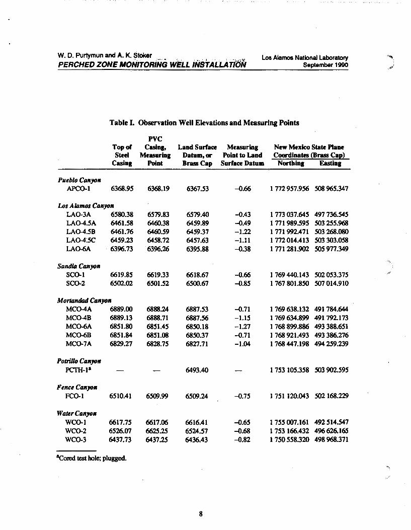
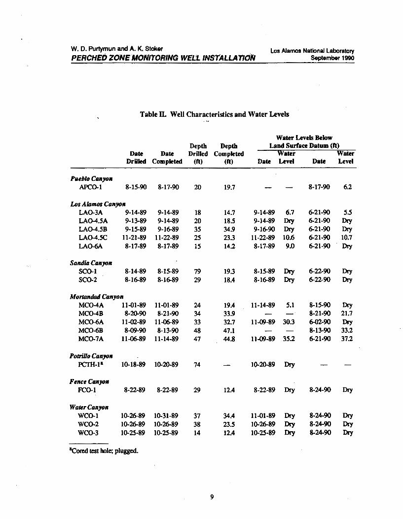
V. OBSERVATION WELLS
The observation well elevations, measuring points (MPs), and coordinates (New Mexico State Plane system) are shown in Table I. Well characteristics are presented in Table D. The log, casing schedule, and construction details for each well are found in Figs. 2 through 15. Locations of the observation wells and
4
W. D. Purtymun and A. K. Stoker PERCHED ZONE AfONrrORINO WELL INSTALLA nON
/
los Alamos National Laboratory September 1990
holes are indicated in Fig. 16. 1be map in Fig. 16 also shows locations of existing monitoring wells that indicate the extent of perched ground water in the canyon alluvial systems. Some alluvial perched ground water can also be inferred to exist in portions of canyons within the facility boundaries where surface stream flow occurs throughout the year. 1bese canyons include the portion of Pueblo Canyon (fed by effluent from the Los Alamos County sanitary sewage treattnent plant), Los Alamos Canyon (fed by flow from the mountains and released from the reservoir), Sandia Canyon (fed by effluent from the TA-3 sanitary sewage treatment plant), Pajarito Canyon (fed by surface run-off from the mountains to the west), and Water Canyon (fed by springs on the flanks of the mountains to the wesQ. These locations are generally-further upstream t;han any of the new monitoring wells, as can be seen by the locations of old monitoring wells that contain water in Los Alamos and Pajarito Canyons (see Fig. 16).
1be wells were located along the eastern third of the plateau. Seven of wells were dry when drilled, and three additional wells (two in Mortandad Canyon and one in Los Alamos Canyon) became dry during the summer because of the lack of surface run-off. Two additional wells were drilled in Mortandad Canyon beCause the old U.S. Geological Survey wells indicated that the water level had declined beneath the lowest pan of the 10-ft screen installed in the first new wells. 1be replacement wells were equipped with 20-ft screen sections to allow for the considerable fluctuation in water level. 1be well in Los Alamos Canyon that is now dry was completed into the top of the underlying basalt, and the aquifer has receded upstream because of limited recharge from run-off. Details of individual wells are discussed below or are shown in the referenced figures.
A. Pueblo C1111yon
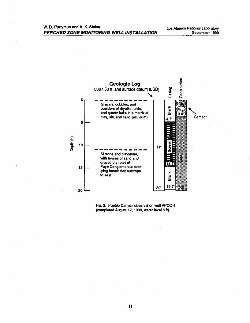
Pueblo Canyon observation well APC0-1 was completed in alluvium underlain by siltstone and claystone. Water was perched in the alluvium (Fig. 2).
B. Los Alamos C1111yo•
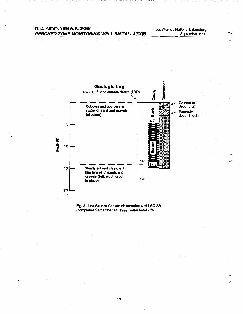
Los Alamos Canyon observation well LA0-3A was completed in alluvium underlain by tuff. Water was perched on the weathered tuff (Fig. 3).
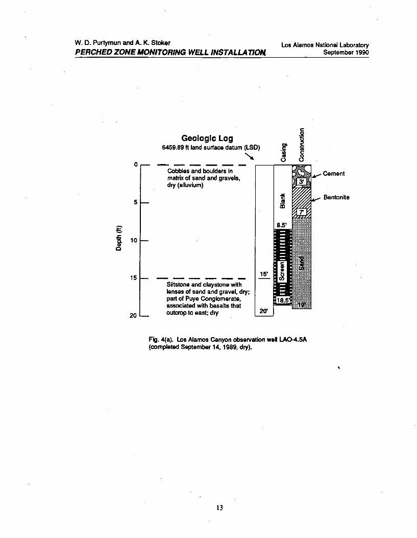
Three wells were completed near LA0-4.5. Two of the wells were dry but were completed as wells because there is a possibility of the alluvium or sand lens in the underlying siltstone and claystone becoming saturated with an increase of storm run-off [Fig. 4(a) and 4(b)]. The siltstone and claystone underlying the alluvium is associated with the basalt that underlies the alluvium to the · east. Water occurs in a sand lens within the siltstone and claystone [Fig. 4(c)].
Los Alamos Canyon observation well LA0-6A was completed through the alluvium into the top of a basalt flow (Fig. 5). The well contained water when
5

W. D. Purtymun and A. K. Stoker
PERCHED ZONE MONITORING WELL INSTALLA. TIQN Los Alamos National Laboratory
September 1990
completed but went dry during the summer as the aquifer retreated up the canyon.
C. Sandia Canyon
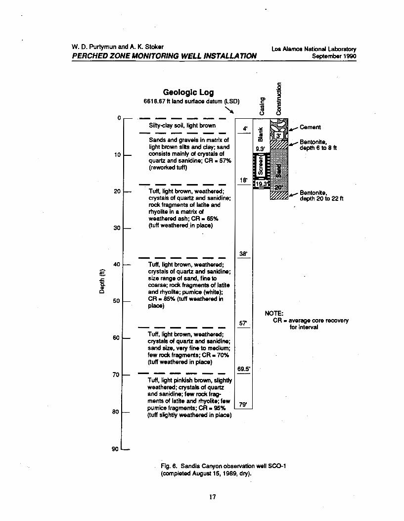
Sandia Canyon observation well SCO-t was completed in alluvium underlain by a weathered tuff. The alluvium was dry (Fig. 6).
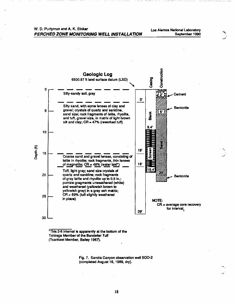
Sandia Canyon observation well SC0-2 was completed in alluvium underlain by a weathered tuff. 1be alluvium was dry (Fig. 7).
Although the alluvium was dry at both locations. the holes were finished as wells because there is a possibility an increase in run-off could saturate part of the alluvium.
D. Morlllndad Canyon
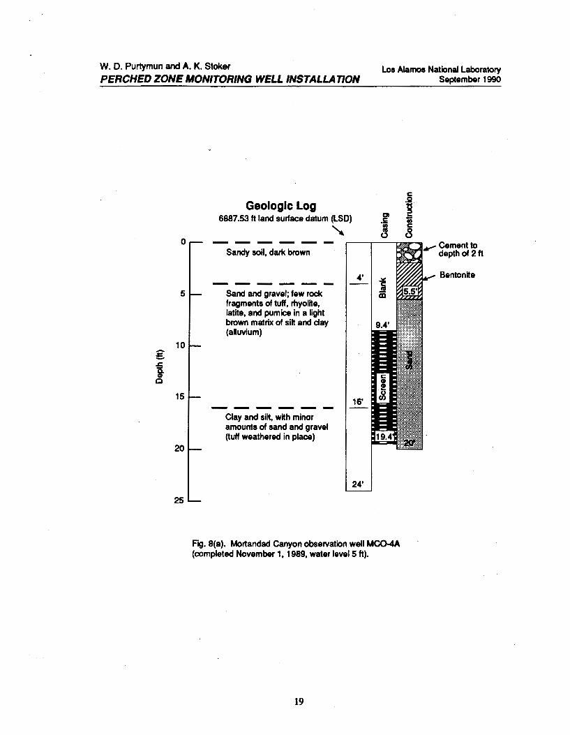
Mortandad Canyon observation well MC0-4A was completed in the alluvium and contained water when completed [Fig. 8(a)]. The well went dry during the summer, and a second well (MC0-4B) was constructed through the alluvium and into the top of the weathered tuff [Fig. 8(b)]. Water was encountered in the alluvium perched above the tuff. The second well was constructed with a 20-ft screen section to allow sampling even with the Wide range of water-level fluctuation in the canyon.
Mortandad Canyon observation well MC0-6A was completed in the alluvium and contained water when completed [Fig. 9(a)]. The well went dry during the summer, and a second well (MC0-6B) was drilled through the alluvium into the top of the weathered tuff [Fig. 9(b)]. Water was encountered in the alluvium above the tuff. The well was equipped with a 20-ft screen section.
Mortandad Canyon observation well MC0-7 A was completed in the alluvium (Fig. 10). The well encountered water in the alluvium.
E. Potrillo Canyon
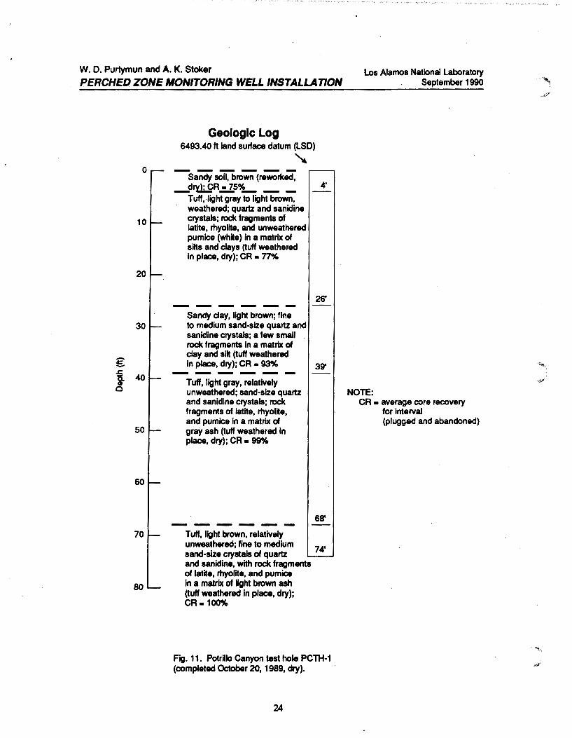
Potrillo Canyon test hole PCTH-1 was cored to a depth of74 ft (Fig. 11). The hole penetrated a thin soil zone of reworked material and a thick section of weathered to unweathered tuff. The entire section was dry and indicated no presence of past water. 1be hole was abandoned and plugged with a cementbentonite slurry.
6

W. D. Purtymun and A. K. Stoker
PERCHED ZONE IIONITORINCJ WEtL INSTALLATION
F. Fence Canyon
Los Alamos National Laboratory September 1990
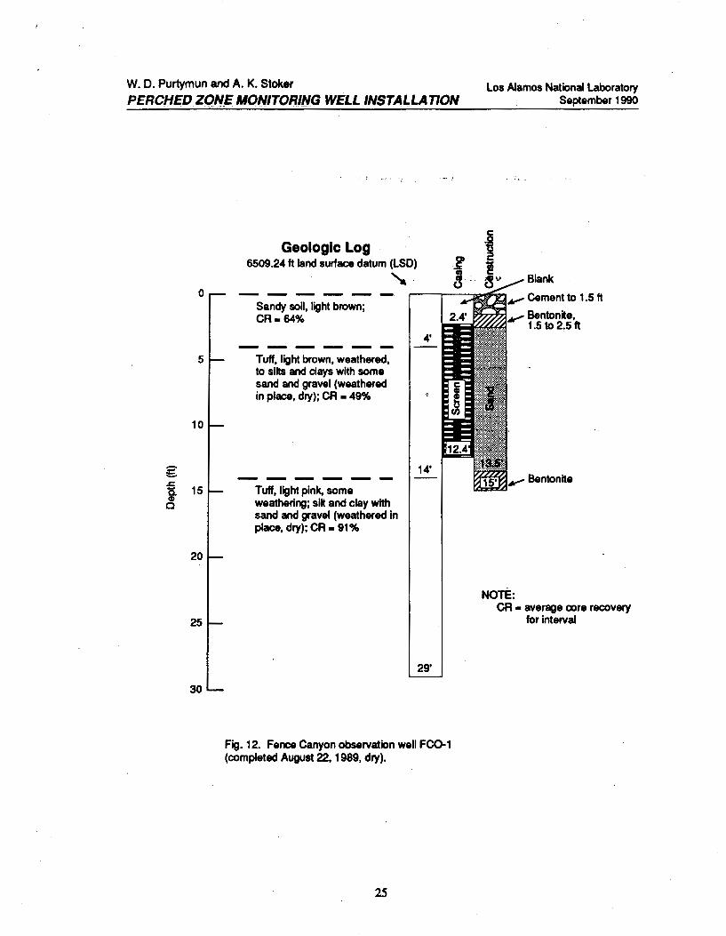
Fence Canyon observation well FC0-1 penetrated a sandy soil underlain by weathered and unweathered tuff (Fig. 12). Tile hole was dry, but was completed as a well.
G. Water Canyon
Water Canyon observation well WC0-1 was completed through the alluvium into the top of weathered ruff (Fig 13). Tile well was dry.
Water Canyon observation well WC0-2 was completed through the alluvium. into the top of weathered tuff (Fig. 14). Tile well was dry.
Water Canyon observation well WC0-3 was completed through the alluvium into the top of basalt (Fig. 15). The well was dry.
The three wells in Water Canyon were dry, but were completed as wells. Water Canyon heads high on the flanks of the mountains west of the plateau. Snowmelt run-off could recharge the alluvium to the extent the wells could contain water.
7
W. D. Purtymun and A. K. Stoker PERCHED ZONE MONITORING WELL INSTALLAiidN
Los Alamos National Laboratory September 1990
Table L Observation Well Elevations and Measuring Points
PVC Topol Casina, Land Surface Measurina New Mexico State Plane Steel Measurina Datum, or Point to Land Coordinates (Brass Ca2)
Casint Point Brass Cap Surface Datum Nortbm1 Eastinl
Pueblo C1111yon APC0-1 6368.95 6368.19 6367.53 ~.66 1 772 957.956 508 965.347
Los Alamos Canyon LA0-3A 6580.38 6579.83 6579.40 ~.43 1 773 037.645 497 736.545 LA0-4.5A 6461.58 6460.38 6459.89 ~.49 1 771 989.595 503 255.968 LA0-4.5B 6461.76 6460.59 6459.37 -1.22 1 771 992.471 503 268.080 LA0-4;5C 6459.23 6458.72 6457.63 -1.11 1 772 014.413 503 303.058 LA0-6A 6396.73 6396.26 6395.88 ~.38 1 771 281.902 505 977.349
Sandia Canyon SC0-1 6619.85 6619.33 6618.67 ~.66 1 769 440.143 502053.375 SC0-2 6502.02 6501.52 6500.67 ~.85 1 767 801.850 507014.910
MortiJ1Uiml Canyon MC0-4A 6889.00 6888.24 6887.53 ~.71 1 769 638.132 491784.644 MC0-4B 6889.13 6888.71 6887.56 -1.15 1 769 634.899 491792.173 MC0-6A 6851.80 6851.45 6850.18 -1.27 1 768 899.886 493 388.651 MC0-6B 6851.84 6851.08 6850.37 ~.71 1 768 921.493 493 386.276 MC0-7A 6829.27 6828.75 6827.71 -1.04 1 768 447.198 494259.239
PotriUo Canyon PCTH-1• 6493.40 1 753 105.358 503 902.595
Fence C1111yon FC0-1 6510.41 6509.99 6509.24 ~.75 1 751 120.043 502 168.229
Water Canyon WC0-1 6617.75 6617.06 6616.41 ~.65 1 755 007.161 492 514.547 WC0-2 6526.07 6625.25 6524.57 ~.68 1 753 166.432 496626.165 WC0-3 6437.73 6437.25 6436.43 ~.82 1 750 558.320 498968.371
SCored test hole; plugged.
8
W. D. Purtymun and A. K. Stoker
PERCHtD ZONE MONITORING WELt. INSTALLA TIOf.l Los Alamos National Laboratory
September 1990
Table ll. Well Characteristics and Water Levels
Water Levels Below Depth Depth Land Surface Datum (It)
Date Date Drilled Completed Water Water Drilled Completed (ft) (It) Date Level Date Level
Pueblo C1U1yo11 APC0-1 8-15-90 8-17-90 20 19.7 8-17-90 6.2
Los A/Qmos Canyo11 LA0-3A 9-14-89 9-14-89 18 14.7 9-14-89 6.7 6-21-90 5.5 LA0-4.5A 9-13-89 9-14-89 20 18.5 9-14-89 Dry 6-21-90 Dry LA0-4.5B 9-15-89 9-16-89 35 34.9 9-16-90 Dry 6-21-90 Dry LA0-4.5C 11-21-89 11-22-89 25 23.3 11-22-89 10.6 6-21-90 10.7 LA0-6A 8-17-89 8-17-89 15 14.2 8-17-89 9.0 6-21-90 Dry
Sandia Ca11yo11 SC0-1 8-14-89 8-15-89 79 19.3 8-15-89 Dry 6-22-90 Dry SC0-2 8-16-89 8-16-89 29 18.4 8-16-89 Dry 6-22-90 Dry
Morta11dad Canyo11 MC0-4A 11-01-89 11-01-89 24 19.4 11-14-89 5.1 8-15-90 Dry MC0-4B 8-20-90 8-21-90 34 33.9 8-21-90 21.7 MC0-6A 11-02-89 11-06-89 33 32.7 11-09-89 30.3 6-02-90 Dry MC0-6B 8-09-90 8-13-90 48 47.1 8-13-90 33.2 MC0-7A 11-06-89 11-14-89 47 44.8 11-09-89 35.2 6-21-90 37.2
PotriUo Ca11yo11 PCTH-1• 10-18-89 10-20-89 74 10-20-89 Dry
Fence CIUiyoll FC0-1 8-22-89 8-22-89 29 12.4 8-22-89 Dry 8-24-90 Dry
Water Canyo11 WC0-1 10-26-89 10-31-89 37 34.4 11-01-89 Dry 8-24-90 Dry WC0-2 10-26-89 10-26-89 38 23.5 10-26-89 Dry 8-24-90 Dry WC0-3 10-25-89 10-25-89 14 12.4 10-25-89 Dry 8-24-90 Dry
&cored test bole; plugged.
9

W. D. Purtymun and A. K. Stoke~ Los Alamos National Laboratory September 1990
.5 ClO
'i
PERCHED ZONE MONITORWlJ WELL INSTALLATION
· d cap, · · h ~ 3-ln.-o. • stee PIP& wit :____-r ~ plate welded on top --J
8.625-in. -o.d. steel casing
Observation well casing (2 in. i.d.)
T .5
\1 1-in. steel plate run through holes in 13-in. cap and 8.625-in.-o.d. casing (hole in bar for lock)
Fig. 1. Two types of wellhead security locks used on canyon observation wells.
10
Observation weH casing (2 in. i.d.)
Hinge ·
I
''""
W. D. Purtymun and A. K. Stoker los Alamos National laboratory September 1990 PERCHED ZONE MONITORING WELL INSTALLATION
0
5
-E. .s::. 15. 10 Gl c
15
20
Geologic Log 6367.53 ft land surface datum (LSD) Q c
~ ·;; as 0 -----------Gravels, cobbles, and
boulders of rhyolite, latite, and quartz latite in a matrix of clay, silt, and sand (alluvium)
-----------Silstone and claystone, with lenses of sand and gravel, dry; part of Puye Conglomerate over-lying basalt that outcrops to east
Fig. 2. Pueblo Canyon obs8rvatlon well APC0-1 (completed August 17, 1990, water level 6ft).
11
c -~ 2 1ii c 8
' Cement
W. D. Purtymun and A. K. Stoker
PERCHED ZONE MONITORING WELL INSTALLATIQN
Geologic Log 6579.40 ft land surface datum (LSD)
'
Los Alamos National Laboratory September 1990
Cobbles and boulders in matrix of sand and gravels (alluvium)
.-------,....---..._.,.....-. .,... Cement to depth of 2ft
Mainly silt and clays, with thin lenses of sands and gravels (tuff, weathered in place)
Fig. 3. Los Alamos Canyon observation well LA0-3A (completed September 14, 1989, water level 7 ft).
12
.,... Bentonite, depth 2 to 3 ft
W. D. Purtymun and A. K. Stoker
PERCHED ZONE MONITORING WELL INSTALLADON,
Geologic Log 6459.89 ft land surface datum (LSD)
' 0 ------
5
-5. .r: a. 10 Gl c
15
20
Cobbles and boulders in matrix of sand and gravels, dry (alluvium)
Siltstone and claystone with lenses of sand and gravel, dry; part of Puye Conglomerate, associated with basalts that outcrop to east; dry
Los Alamos National Laboratory September 1990
c:
1 c:
8 Cement
Bentonite
Fig. 4(a). Los Alamos Canyon observation weH LA0-4.5A (completed September 14, 1989, dry).
'
13

W. D. Purtymun and A. K. Stoker
PERCHED ZONE MONITORING WELL INSTALLATION
-£ J:. a CD 0
Geologic Log 6459.37 ft land surface datum (LSD)
' 0 ------
5
15
20
25
30
35
Cobbles and boulders in matrix of sand and gravel, dry (alluvium)
Siltstone and claystone, with lenses of sand and gravel, saturated; lenses of sand sealed out of well above 25 ft, lower section dry; part of Puye Conglomerate and associated basalt to east
Los Alamos National Laboratory September 1990
c .1:2
~ 1ii c
8
...., Bentonite
Fig. 4(b). Los Alamos Canyon observation well LA0-4.58 (completed September 16, 1989, dry)
14

W. D. Purtymun and A. K. Stoker Los Alamos National Laboratory September 1990 PERCHED ZONE MONJTORIIIQ. V!(~L.INS.'f~LLATION.
-£
1
Geologic Log 6457.63 ft land surface datum (LSD)
~ 0 ------
5
10
Cobbles and boulders in matrix of sands and gravels, dry (alluvium)
15 ------
20
25
Siltstone and claystone, with lenses of sand and gravel; part of Puye Conglomerate and associated basalts to east
Fig. 4(c). Los Alamos Canyon observation well LA0-4.5C (completed November 22, 1989, water level 11 ft).
15

W. D. Purtymun and A. K. Stoker
PERCHED ZONE MONITORING WELL INSTALLATION
Geologic Log 6395.88 ft land surface datum (LSD)
' 0 ------Cobbles and boulders in matrix of sand and gravel (alluvium)
5 -:!:. .s:; a Gl c
10
-----Top of basalt, gravels
15 and clay
Q c
·= 0
los Alamos National laboratory September 1990
c .S2 ~ ... 1ii c
8 Cement to At" depth of 1 ft
.......,Bentonite, depth 1 to 2 ft
Fig. 5. los Alamos Canyon observation welllA0-6A (completed August 17, 1989, water level 9.0 ft).
16
W. D. Purtymun and A. K. Stoker Los Alamos National Laboratory September 1990 PERCHED ZONE MONITORING WELL INSTALLATION
0
10
20
30
40 -E. .s::. c. Cll 0
50
60
70
80
90
Geologic Log 6618.67 ft land surface datum (LSD)
' ·------Silty-clay soil, light brown 4' ------Sands and gravels in matrix of light brown silts and day; sand consists mainly of crystals of quartz and sanidine; CR • 57% (rewoi'Ked tuff)
18' ---- --Tuff, light brown, weathered; crystals of quartz and sanidine; rock fragments of latite and rhyolite in a matrix of weathered ash; CR • 65% (tuff weathered in place)
38' ------Tuff, light brown, weathered; crystals of quartz and sanidine; size range of sand, fine to coarse; rock fragments of latite and rhyolite; pumice (white); CR • 85% (tuff weathered in place)
c .12
~ ~ ! ·;; (3 8
NOTE:
Cement
Bentonite, depth 6 to 8 ft
Bentonite, depth 20 to 22 ft
57' CR • average core recovery ------Tuff, light brown, weathered; crystals of quartz and sanidine; sand size, very fine to medium; few rock fragments; CR • 70% (tuff weathered in place)
69.5' -----Tuff, light pinkish brown, slightly weathered; crystals of quartz and sanidine; few rock frag-ments of latite and rhyolite; few
79' pumice fragments; CR • 95% (tuff slightly weathered in place)
Fig. 6. Sandia Canyon observation well SC0-1 (completed August 15, 1989, dry).
17
for interval
W. D. Purtymun and A. K. Stoker
PERCHED ZONE MONITORING WELL INSTALLATION
Geologic Log 6500.67 ft land surface datum (LSD)
' 0 --------
5
10
R 15 CD c
20
25
30
Silty-sandy soil, gray
Silty sand, with some lenses of clay and gravel; crystals of quartz and sanidine, sand size; rock fragments of latite, rhyolite, and tuff, gravel size, in matrix of light brown silt and clay; CR • 47% (reworked tuff)
--------Coarse sand and gravel lenses, consisting of latite in rhyolite; rock fragments, thin lenses
3'
15'
_of magn!!,!!!; <2!!,: 4,!!. (w.!!!!" laid*) 18'
Tuff, light gray; sand size crystals of quartz and sanidine; rock fragments of gray latite and rhyolite up to 0.5 in.; pumice gragments unweathered (white) and weathered (yellowish brown to yellowish gray) in a gray ash matrix; CR • 69% (tuff slightly weathered in place)
*This 3-ft interval is apparently at the bottom of the Tshirege Member of the Bandelier Tuff (Tsankawi Member, Bailey 1967).
29'
Los Alamos National Laboratory September 1990
Cement
Bentonite
Bentonite
NOTE: CR • average core recovery
for interval. \
Fig. 7. Sandia Canyon observation well sco-2 (completed August 16, 1989, dry).
18
W. D. Purtymun and A. K. Stoker Los Alamos National Laboratory September 1990 PERCHED ZONE MONITORING WELL INSTALLA nON
0
5
10 -£ s:; a CD
0
15
20
25
Geologic Log 6887.53 ft land surface datum (LSD) .e'
' = 0 -----Sandy soil, dark brown
------Sand and gravel; few rock fragments of tuff, rhyolite, latite, and pumice in a light brown matrix of silt and clay (alluvium)
------Clay and silt, with minor amounts of sand and gravel (tuff weathered in place)
Fig. 8(a). Mortandad Canyon observation well MC0-4A (completed November 1, 1989, water level 5 ft).
19
c .S2 ts ~ ... -;; c 8
Cement to depth of 2ft
Bentonite

W. D. Purtymun and A. K. Stoker
PERCHED ZONE MONITORING WELL INSTALLATION
g .c. a Cll c
Geologic Log 6887.56 ft land surface datum (LSD)
'
c .S2
~ 1ii c
8 0 -----
5
10
15
20
25
30
35
Sandy soil, dark brown CR· 65%
Sand and gravel; a few rock fragments of tuff, rhyolite, latite, and pumice in a matrix of silts and clay (alluvium) CR. 53%
-- ----Silts, clay, and coarse sand, alternating; some rock fragments of rhyolite, latite, and pumice (tuff weathered in place); CR • 86%
-- --- -Tuff, dark brown, weathered to silts and clays CR • 96%
Fig. 8(b). Mortandad Canyon observation well MC0-48 (completed August 21, 1990, water level 22 ft).
20
Los Alamos National Laboratory September 1990
Cement
NOTE: CR • average core recovery
for interval.

W. D. Purtymun and A. K. Stoker
PERCHED ZONE MONITORING WELL INSTALLATION
g
Geologic Log 6850.18 ft land surface datum (LSD)
~ 0 --~---
Sandy soil
Sands and gravels; a few rock 5 fragments of tuff, pumice, latite,
and rhyolite, and pumice in a brown silt and clay matrix (reworked tuff)
10
15
.J:. 20 i c
25
30
35
40
------Silts and clays with fine to coarse sand; rock fragments of rhyolite, latite, and pumice; sand-size fragments; quartz and sanidine crystals and crystal fragments (tuff weathered in place)
Los Alamos National Laboratory September 1990
Bentonite
Fig. 9(a). Mortandad Canyon observation well MCQ-6A (completed November 6, 1989, water level 30 ft).
21

W. D. Purtymun and A. K. Stoker -·l
PERCHED ZONE MONITORING WELL INSTALLATION
Geologic Log 6850.37 ft land surface datum (LSD)
g
~-0 ------
Sands and gravels; a few rock fragments of tuff, latite, rhyolite, and pumice in a brown silt and clay matrix (reworked tuff);
5 CR-57%
10
15
20
------Silts and clays, with sands,
~ 25 "i-
rock fragments of latite, rhyolite, tuff, and pumice; a few lenses of sand and clay at 33 to 38 ft, saturated (tuff weathered in place, alluvium) CR. 75%
0
30
35
40
45
50
------Tuff, brown, weathered to silts and clays, with some rock fragments of rhyolite and latite, dry; CR • 100%
23'
40'
22
Los Alamos National Laboratory September 1990
Bentonite
CA • average core recovery for interval.
Fig. 9(b). Mortandad Canyon observation well MCQ-68 (completed August 13, 1990, water level 33 ft).

W. D. Purtymun anetA. K. Stoker ''·'i"' ··~ -· 1 .•• .- .. n. :'"
PERCHED ZONE MONITORING WELL INSTALLATION
-£
Geologic Log 6827.71 ft land surface datum (LSD)
' 0 ------Sandy soil
Sands and gravels; a few rock 5 fragments of tuff, pumice, latite,
10
15
20
and rhyolite in a brown silt and clay matrix (reworked tuff)
Silts and clay with minor amounts of sand and gravel;
.t::. 25 i
a few rock fragments of latite, rhyolite, and weathered pumice up to 0.5 in. (tuff weathered in place)
c
30
35
Mainly silts and clays, with fine to medium sand-size
40 crystals of quartz and sanidine; a few rock fragments up to 0.25 in. (tuff weathered in place)
45
50
23
3'
22'
los Alamos National laboratory September 1990
Bentonite
\
Fig. 10. Mortandad Canyon observation well MC0-7 A (completed November 14, 1989, water level 35 ft).
W. D. Purtymun and A. K. Stoker
PERCHED ZONE MONITORING WELL INSTALLA nON
0
10
20
30
-5. ~
} 40 0
50
60
70
80
Geologic Log 6493.40 ft land surface datum (LSD)
~ ------Sandy soil, brown (rewori<ed, _d'Xli£R..:.l5L __
Tuff,.light gray to light brown, weathered; quartz and sanidine crystals; rock fragments of latite, rhyolite, and unweathered pumice (white) in a matrix of silts and clays (tuff weathered in place, dry); CR • 77%
------Sandy day, light brown; fine to medium sand-size quartz and sanidine crystals; a few small rock fragments in a matrix of clay and silt (tuff weathered in place, dry); CR • 93% ------Tuff, light gray, relatively unweathered; sand-size quartz and sanidine crystals; rock fragments of latite, rhyolite, and pumice in a matrix of gray ash (tuff weathered in place, dry); CR • 99%
Tuff, light brown, relatively unweathered; fine to medium sand-size crystals of quartz and sanidine, with rock fragments of latite, rhyolite, and pumice in a matrix of light brown ash (tuff weathered in place, dry); CR-100%
4'
26'
39'
68'
74'
Fig. 11. Potrillo Canyon test hole PCTH-1 (completed October 20, 1989, dry).
24
Los Alamos National Laboratory September 1990
NOTE: CR • average core recovery
for interval (plugged and abandoned)
. .,., ;;,*"
~·'
W. D. Purtymun and A. K. Stoker
PERCHED ZOII_~ MON_ITOR/N_G WELL INSTALLATION
0
5
10
g .c 0. 15 Gl c
20
25
30
Geologic Log 6509.24 ft land surface datum (LSD)
' -----Sandy soil, light brown; CR-64%
4' --- ---Tuff, light brown, weathered, to silts and clays with some sand and gravel (weathered in place, dry); CR • 49%
14' ------Tuff, light pink, some weathering; silt and clay with sand and gravel (weathered in place, dry); CR • 91%
29'
Fig. 12. Fence Canyon observation well FCQ-1 (completed August 22, 1989, dry).
25
Los Alamos National Laboratory September 1990
Blank
Cement to 1.5 ft
Bentonite, 1.5 to 2.5 ft
Bentonite
NOTE: CR • average core recovery
for interval

W. D. Purtymun and A. K. Stoker
PERCHED ZONE MONITORIN(i WELL INSTALLA nON
-~ .J: a • 0
Geologic Log 6616.41 ft land surface datum (LSD)
' 0 ------
5
10
15
20
25
30
35
40
Gravels, cobbles, and boulders in a matrix of silts and clays, dry (alluvium)
---- - -Tuff, reworked, weathered; clays and silts, with minor amounts of sands and gravels (near saturation)
---- - -Tuff, weathered as above, but dry
24'
32'
37'
F1g. 13. Water Canyon observation well WC0-1 (completed October 31, 1989, dry).
26
Los Alamos National Laboratory September 1990
Bentonite
,J'

W. D. Purtymun and A. K. Stoker
PERCHED ZONE MONITORING WELL INSTALLATION
-£
Geologic Log 6624.57 ft land surface datum (LSD)
' 0 ------
5
10
15
Gravels, cobbles, and boulders in matrix of clays, silts, and sands, dry (alluvium)
.s:: 20 } Q
25
30
Tuff, weathered; clays and silts, with minor amounts of sand (dry); rock fragments, 29 to 30 ft (dry)
------Tuff, light brown, only slightly
35 weathered (dry)
40
21'
38'
Los Alamos National Laboratory September 1990
Bentonite
Fig. 14. Water Canyon observation well WC0-2 (co":'pleted October 26, 1989, dry).
27

W. D. Purtymun and A. K. Stoker Los Alamos National Laboratory September 1990 PERCHED ZONE MONITORING WELL IN$TALLATION
0
5
g .s:; l5. • Q
10
15
Geologic Log 6436.43 ft land surface datum (LSD) ~
' ~ ------Gravels, cobbles, and boulders in a matrix of clays, silts, and sands (dry)
11' -----Basalt, dense, weathered (dry)
14'
Fig. 15. Water Canyon observation well WCQ-3 (completed October 25, 1989, dry).
28
c .Q
I c 8
Cement
Bentonite
'
' <,