PDS-201-2 HDB3
5
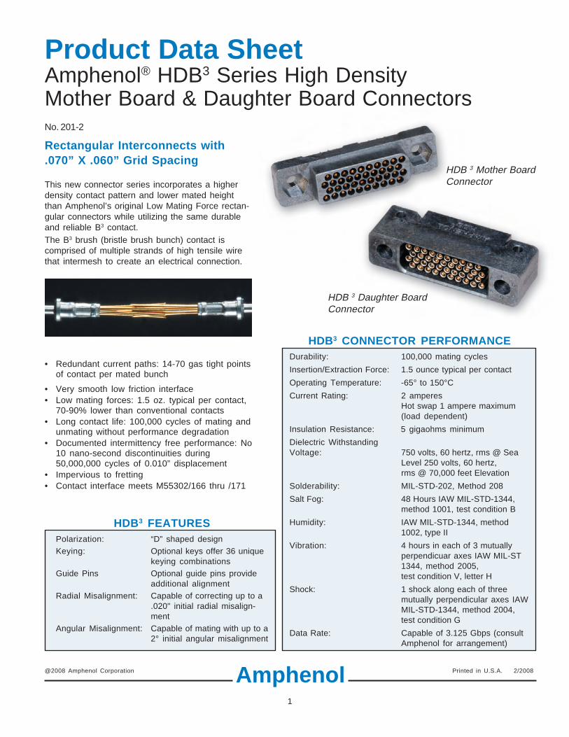
1 Product Data Sheet Amphenol ® HDB 3 Series High Density Mother Board & Daughter Board Connectors No. 201-2 Rectangular Interconnects with .070” X .060” Grid Spacing This new connector series incorporates a higher density contact pattern and lower mated height than Amphenol’s original Low Mating Force rectan- gular connectors while utilizing the same durable and reliable B 3 contact. The B 3 brush (bristle brush bunch) contact is comprised of multiple strands of high tensile wire that intermesh to create an electrical connection. Amphenol HDB 3 Mother Board Connector HDB 3 Daughter Board Connector BENEFITS OF THE BRUSH CONTACT • Redundant current paths: 14-70 gas tight points of contact per mated bunch • Very smooth low friction interface • Low mating forces: 1.5 oz. typical per contact, 70-90% lower than conventional contacts • Long contact life: 100,000 cycles of mating and unmating without performance degradation • Documented intermittency free performance: No 10 nano-second discontinuities during 50,000,000 cycles of 0.010” displacement • Impervious to fretting • Contact interface meets M55302/166 thru /171 @2008 Amphenol Corporation Printed in U.S.A. 2/2008 HDB 3 FEATURES Polarization: “D” shaped design Keying: Optional keys offer 36 unique keying combinations Guide Pins Optional guide pins provide additional alignment Radial Misalignment: Capable of correcting up to a .020" initial radial misalign- ment Angular Misalignment: Capable of mating with up to a 2° initial angular misalignment HDB 3 CONNECTOR PERFORMANCE Durability: 100,000 mating cycles Insertion/Extraction Force: 1.5 ounce typical per contact Operating Temperature: -65° to 150°C Current Rating: 2 amperes Hot swap 1 ampere maximum (load dependent) Insulation Resistance: 5 gigaohms minimum Dielectric Withstanding Voltage: 750 volts, 60 hertz, rms @ Sea Level 250 volts, 60 hertz, rms @ 70,000 feet Elevation Solderability: MIL-STD-202, Method 208 Salt Fog: 48 Hours IAW MIL-STD-1344, method 1001, test condition B Humidity: IAW MIL-STD-1344, method 1002, type II Vibration: 4 hours in each of 3 mutually perpendicuar axes IAW MIL-ST 1344, method 2005, test condition V, letter H Shock: 1 shock along each of three mutually perpendicular axes IAW MIL-STD-1344, method 2004, test condition G Data Rate: Capable of 3.125 Gbps (consult Amphenol for arrangement)
Transcript of PDS-201-2 HDB3
1
Product Data SheetAmphenol® HDB3 Series High DensityMother Board & Daughter Board ConnectorsNo. 201-2
Rectangular Interconnects with.070” X .060” Grid Spacing
This new connector series incorporates a higherdensity contact pattern and lower mated heightthan Amphenol’s original Low Mating Force rectan-gular connectors while utilizing the same durableand reliable B3 contact.The B3 brush (bristle brush bunch) contact iscomprised of multiple strands of high tensile wirethat intermesh to create an electrical connection.
Amphenol
HDB 3 Mother BoardConnector
HDB 3 Daughter BoardConnector
BENEFITS OF THE BRUSH CONTACT• Redundant current paths: 14-70 gas tight points
of contact per mated bunch
• Very smooth low friction interface• Low mating forces: 1.5 oz. typical per contact,
70-90% lower than conventional contacts• Long contact life: 100,000 cycles of mating and
unmating without performance degradation• Documented intermittency free performance: No
10 nano-second discontinuities during50,000,000 cycles of 0.010” displacement
• Impervious to fretting• Contact interface meets M55302/166 thru /171
@2008 Amphenol Corporation Printed in U.S.A. 2/2008
HDB3 FEATURESPolarization: “D” shaped designKeying: Optional keys offer 36 unique
keying combinationsGuide Pins Optional guide pins provide
additional alignmentRadial Misalignment: Capable of correcting up to a
.020" initial radial misalign-ment
Angular Misalignment: Capable of mating with up to a2° initial angular misalignment
HDB3 CONNECTOR PERFORMANCEDurability: 100,000 mating cycles
Insertion/Extraction Force: 1.5 ounce typical per contact
Operating Temperature: -65° to 150°C
Current Rating: 2 amperesHot swap 1 ampere maximum(load dependent)
Insulation Resistance: 5 gigaohms minimum
Dielectric WithstandingVoltage: 750 volts, 60 hertz, rms @ Sea
Level 250 volts, 60 hertz,rms @ 70,000 feet Elevation
Solderability: MIL-STD-202, Method 208
Salt Fog: 48 Hours IAW MIL-STD-1344,method 1001, test condition B
Humidity: IAW MIL-STD-1344, method1002, type II
Vibration: 4 hours in each of 3 mutuallyperpendicuar axes IAW MIL-ST1344, method 2005,test condition V, letter H
Shock: 1 shock along each of threemutually perpendicular axes IAWMIL-STD-1344, method 2004,test condition G
Data Rate: Capable of 3.125 Gbps (consultAmphenol for arrangement)

2
.350 .350 .325 .086 MIN.THRU HOLE(USE NO. 2 SCREW)
PIN 1 PIN 1
B A
.086 MIN.THRU HOLE(USE NO. 2 SCREW)
CBA
.335 MAX..150 ±.005
.150 ±.020TYP.
.150 ±.020TYP.
.016 ±.001TYP.
.016 ±.001TYP.
.195 MIN. HEX
.070 MIN DEEP(USE 3/16 HEX HEAD)
.090 TYP..030 TYP.
.035TYP.
.070TYP.
.060 TYP. .025
.540
.420
.350.410.470.530
46
5
12
3
DF
E
AB
C
12
36
54
AB
CF
ED
No. of A B CContacts
40 1.375 1.075 0.630
80 2.075 1.775 1.330
120 2.775 2.475 2.030
160 3.475 3.175 2.730
Dimensions
HDB3 MATERIALSInsulator: Liquid crystal polymer, 30% glass filledContact: Wire: Beryllium copper per ASTM B197; finish is gold per ASTM B488
over nickel per AMS-QQ-N-290.Holder: Brass similar to UNS C33500; finish is gold per MIL-G-45204 or tin-lead per
MIL-P-81728 or tin per MIL-T-10727 (RoHS Compliant).Sleeve: Stainless Steel per AMS-5514, passivated IAW QQ-P-35
(Daughter Board connector only)Keys/Guide Pins: Stainless Steel
MOTHER BOARD DAUGHTER BOARD
All dimensions for reference only.
CUSTOM CONFIGURATIONS• Hybrid configurations are available with any combination
of brush and power, coax, and/or fiber optic contacts• Partially populated arrangements for high voltage or high
speed data transfer up to 3.125 Gbps. (shown at right)Consult Amphenol Aerospace with your design requirements.

3
HDB3 MOTHER BOARD CONNECTOR HOW TO ORDER
HDB-M4 - 040 M 20 2 X
HDB-M4 Designates HDB3 Mother Board Connectors
Number of ContactsNumber of Dimension Dimension DimensionContacts A B C
040 40 1.375 0.800 1.075
080 80 2.075 1.500 1.775
120 120 1.775 2.200 2.475
160 160 3.475 2.900 3.175
Brush Wire PlatingM 0.000050 Au Min. thick over NickelC 0.000020 Au Min. thick over Nickel
Termination
Example part number:Hardware
Type Stickout(Dim. K)
X No Hardware N/A
G Polarization Key 0.250Qty. 2
H Polarization Key 0.500Qty. 2
J Polarization Key 0.750Qty. 2
T Guide Pin 0.250Qty. 2
U Guide Pin 0.500Qty. 2
V Guide Pin 0.750Qty. 2Type Stickout
(Dim. E)20 PCB, Straight, .016 Dia. 0.060
21 PCB, Straight, .016 Dia 0.090
22 PCB, Straight, .016 Dia 0.120
23 PCB, Straight, .016 Dia 0.150
24 PCB, Straight, .016 Dia 0.180
25 PCB, Straight, .016 Dia 0.210
Contact Terminition Finish2 Gold plated in accordance with
MIL-G-45204, Type II, .00030 Min.thick Gold over .000050 Min. thickNickel
5 Tin plated in accordance withASTM B545, .00010 Min. thickMatte Tin over .00010 Min. thickNickel
6 Tin-Lead plated in accordance withSAE-AMS-P-81728, .00010 Min.thick Tin-Lead over .00010 Min.thick Copper
HDB-M4-XXXXXXXX drawing is available on-line atwww.amphenol-aerospace.com. Then go to board level, then go to HDB3.
Type Stickout(Dim. E)
26 PCB, Straight, .016 Dia 0.240
27 PCB, Straight, .016 Dia 0.270
28 PCB, Straight, .016 Dia 0.300
29 PCB, Straight, .016 Dia 0.360
30 PCB, Straight, .016 Dia 0.420
HDB3 DAUGHTER BOARD CONNECTOR HOW TO ORDER
HDB-D4 - 040 M 02 2 X
HDB-D4 Designates HDB3 Daughter Board Connectors
Number of ContactsNumber of Dimension Dimension DimensionContacts A B C
040 40 1.375 0.800 1.075
080 80 2.075 1.500 1.775
120 120 1.775 2.200 2.475
160 160 3.475 2.900 3.175
Brush Wire PlatingM 0.000050 Au Min. thick over NickelC 0.000020 Au Min. thick over Nickel
Termination
Example part number:
HardwareType
X No Hardware
P Polarization KeyQty. 2
L Polarization KeyQty. 2
Type Stickout(Dim. E)
00 PCB, Right Angle, .016 Dia. 0.060
01 PCB, Right Angle, .016 Dia. 0.090
02 PCB, Right Angle, .016 Dia. 0.120
03 PCB, Right Angle, .016 Dia. 0.150
04 PCB, Right Angle, .016 Dia. 0.180
05 PCB, Right Angle, .016 Dia. 0.210
06 PCB, Right Angle, .016 Dia. 0.300
HDB-D4-XXXXXXXX drawing is available on-line atwww.amphenol-aerospace.com. Then go to board level, then go to HDB3.
Contact Terminition Finish2 Gold plated in accordance with
MIL-G-45204, Type II, .00030 Min.thick Gold over .000050 Min. thickNickel
5 Tin plated in accordance withASTM B545, .00010 Min. thickMatte Tin over .00010 Min. thickNickel
6 Tin-Lead plated in accordance withSAE-AMS-P-81728, .00010 Min.thick Tin-Lead over .00010 Min.thick Copper
4
Recommended Mother Board Layout Recommended Daughter Board Layout
No. of Contacts B
40 1.075
80 1.775
120 2.475
160 3.175
Dimensions
B
.070
.060
.205
.035.030
FINISHED HOLE SIZE PERCUSTOMER STANDARDS FORA .016 PCB TAIL
.005 M
.110 ±.005
B
.025
.300
.150
.205
.070.035
.060
FINISHED HOLE SIZE PERCUSTOMER STANDARDS FORA .016 PCB TAIL
BOARDEDGE
.005 M
.110 ±.005
Mother Board Connector Keying (Optional)
Daughter Board Connector Keying (Optional)
.680
.620
.560
.500
MOTHERBOARD
DAUGHTERBOARD
MOTHERBOARDCONNECTOR
DAUGHTERBOARDCONNECTOR
Mated Connector Pair Assembledto Boards (0.680” Total Mated Height)
5
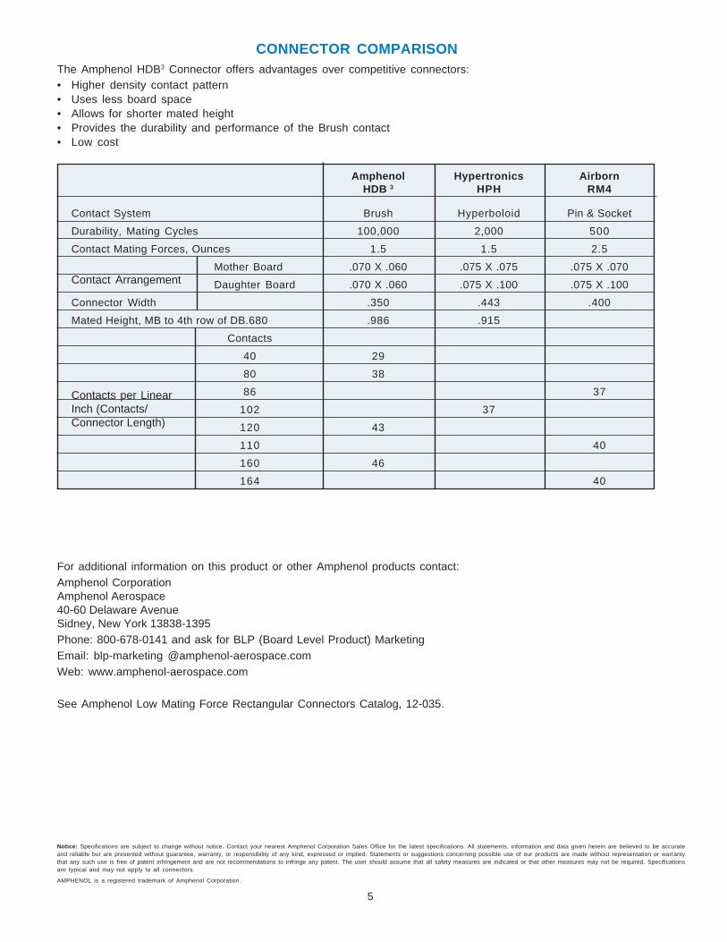
CONNECTOR COMPARISONThe Amphenol HDB3 Connector offers advantages over competitive connectors:• Higher density contact pattern• Uses less board space• Allows for shorter mated height• Provides the durability and performance of the Brush contact• Low cost
Contact System Brush Hyperboloid Pin & Socket
Durability, Mating Cycles 100,000 2,000 500
Contact Mating Forces, Ounces 1.5 1.5 2.5
Mother Board .070 X .060 .075 X .075 .075 X .070
Daughter Board .070 X .060 .075 X .100 .075 X .100
Connector Width .350 .443 .400
Mated Height, MB to 4th row of DB.680 .986 .915
Contacts
40 29
80 38
86 37
102 37
120 43
110 40
160 46
164 40
Amphenol Hypertronics AirbornHDB 3 HPH RM4
Notice: Specifications are subject to change without notice. Contact your nearest Amphenol Corporation Sales Office for the latest specifications. All statements, information and data given herein are believed to be accurateand reliable but are presented without guarantee, warranty, or responsibility of any kind, expressed or implied. Statements or suggestions concerning possible use of our products are made without representation or warrantythat any such use is free of patent infringement and are not recommendations to infringe any patent. The user should assume that all safety measures are indicated or that other measures may not be required. Specificationsare typical and may not apply to all connectors.
AMPHENOL is a registered trademark of Amphenol Corporation.
For additional information on this product or other Amphenol products contact:Amphenol CorporationAmphenol Aerospace40-60 Delaware AvenueSidney, New York 13838-1395Phone: 800-678-0141 and ask for BLP (Board Level Product) MarketingEmail: blp-marketing @amphenol-aerospace.comWeb: www.amphenol-aerospace.com
See Amphenol Low Mating Force Rectangular Connectors Catalog, 12-035.
Contact Arrangement
Contacts per LinearInch (Contacts/Connector Length)


![Dangc Pds 71 Pds Ngc Model700[1]](https://static.fdocuments.us/doc/165x107/577cc1111a28aba71192272d/dangc-pds-71-pds-ngc-model7001.jpg)