Flash Cycle and Binary Geothermal Power Plant …pubs.geothermal-library.org/lib/grc/1030365.pdfAlso...
6
GRC Transactions, Vol. 36, 2012 1079 Keywords Geothermal power plant, binary cycle, flash cycle, optimiza- tion, EES ABSTRACT This research was conducted to provide a guide or reference that could quickly and easily be used to determine the optimum power output and choose the most efficient energy conversion technology. Three energy conversion models were analyzed and simulated. A single flash plant was chosen as the main energy conversion system due to its simplicity and reliability. Two other energy conversion systems were considered as the bottoming unit of the single flash, double flash and Organic Rankine Cycle (ORC). Also their combination with district heating system was investigated. Engineering equation solver software (EES) was used for modeling and simulation. Comparison of power output for three cycles show that ORC cycle is more efficient from the view of power output. Also it has the highest thermal efficiency when district heating is added for heat recovery of waste heat from plant. Introduction The increase in energy demands, decline in energy resources and the link between energy utilization and environmental impact have resulted in calls for sustainable approach to the develop- ment and management of the earth’s energy resources (Rosen and Dincer, 2001). With finite energy resources and increasing energy demands, it becomes increasingly important to understand the mechanisms which degrade the quality of energy and energy resources and to develop systematic approaches to improve energy conversion systems (Gong and Wall, 1997). There are several available energy conversion systems for utilization of geothermal resources and advanced technology has provided more choices for decision makers. It seems to be very useful to develop a bottom key method that can give a quick and relatively accurate idea for developers to compare different avail- able options for power plant installation. Generation of electricity using geothermal resources has been practiced for more than a century, since its first use at the Lardarel- lo geothermal field in Italy, in 1904. The steam Rankin cycle has been the conventional technology used for most worldwide geothermal power generation to date. Various technical enhance- ments to the condensing steam turbines have been implemented over the years to address the differences between geothermal and boiler-quality steam. The most attractive geothermal fields for developers have been those with high resource temperatures and production fluid enthalpies. These fields can deliver at higher pressures and steam flash proportions in order to achieve more efficient operation of the condensing steam turbines, and hence lower electricity production costs. Condensing steam plants are typically used for resource temperatures in excess of 200°C. For a low-enthalpy resource, a low operating pressure is needed to obtain a reasonable steam flash, equipment is larger and hence more expensive, and a significant proportion of the available energy in the production fluid is rejected in the separated brine. There are several experienced and competent providers around the world for steam-turbine geothermal power plants and component equipment. Turbine-generator unit capacities are typically in the 20-80 MWe range, but are offered from less than 5 MWe up to 110 MWe (Dipippo, 2008). This paper presents the design process of geothermal power utilization for production of electricity and management of waste heat, from three geothermal wells with given enthalpies and mass flows. The project involved designing process of geothermal power plant according to three cycles named single flash, double flash and binary cycle. Calculations and simulations have been done with Engineering Equations Solver (EES) software. Optimi- zation to find wellhead pressure and high-side pressure in binary cycle which gives the most power production also has been done for all cycles. Waste heat from three plants has been managed to be used in district heating system or to be used for additional binary cycle power production. Flash Cycle and Binary Geothermal Power Plant Optimization Saeid Jalilinasrabady and Ryuichi Itoi Department of Earth Resources Engineering, Faculty of Engineering, Kyushu University, Fukuoka, Japan [email protected]
Transcript of Flash Cycle and Binary Geothermal Power Plant …pubs.geothermal-library.org/lib/grc/1030365.pdfAlso...

GRC Transactions, Vol. 36, 2012
1079
KeywordsGeothermal power plant, binary cycle, flash cycle, optimiza-tion, EES
ABSTRACT
This research was conducted to provide a guide or reference that could quickly and easily be used to determine the optimum power output and choose the most efficient energy conversion technology. Three energy conversion models were analyzed and simulated. A single flash plant was chosen as the main energy conversion system due to its simplicity and reliability. Two other energy conversion systems were considered as the bottoming unit of the single flash, double flash and Organic Rankine Cycle (ORC). Also their combination with district heating system was investigated. Engineering equation solver software (EES) was used for modeling and simulation. Comparison of power output for three cycles show that ORC cycle is more efficient from the view of power output. Also it has the highest thermal efficiency when district heating is added for heat recovery of waste heat from plant.
Introduction
The increase in energy demands, decline in energy resources and the link between energy utilization and environmental impact have resulted in calls for sustainable approach to the develop-ment and management of the earth’s energy resources (Rosen and Dincer, 2001). With finite energy resources and increasing energy demands, it becomes increasingly important to understand the mechanisms which degrade the quality of energy and energy resources and to develop systematic approaches to improve energy conversion systems (Gong and Wall, 1997).
There are several available energy conversion systems for utilization of geothermal resources and advanced technology has provided more choices for decision makers. It seems to be very useful to develop a bottom key method that can give a quick and
relatively accurate idea for developers to compare different avail-able options for power plant installation.
Generation of electricity using geothermal resources has been practiced for more than a century, since its first use at the Lardarel-lo geothermal field in Italy, in 1904. The steam Rankin cycle has been the conventional technology used for most worldwide geothermal power generation to date. Various technical enhance-ments to the condensing steam turbines have been implemented over the years to address the differences between geothermal and boiler-quality steam. The most attractive geothermal fields for developers have been those with high resource temperatures and production fluid enthalpies. These fields can deliver at higher pressures and steam flash proportions in order to achieve more efficient operation of the condensing steam turbines, and hence lower electricity production costs. Condensing steam plants are typically used for resource temperatures in excess of 200°C. For a low-enthalpy resource, a low operating pressure is needed to obtain a reasonable steam flash, equipment is larger and hence more expensive, and a significant proportion of the available energy in the production fluid is rejected in the separated brine. There are several experienced and competent providers around the world for steam-turbine geothermal power plants and component equipment. Turbine-generator unit capacities are typically in the 20-80 MWe range, but are offered from less than 5 MWe up to 110 MWe (Dipippo, 2008).
This paper presents the design process of geothermal power utilization for production of electricity and management of waste heat, from three geothermal wells with given enthalpies and mass flows. The project involved designing process of geothermal power plant according to three cycles named single flash, double flash and binary cycle. Calculations and simulations have been done with Engineering Equations Solver (EES) software. Optimi-zation to find wellhead pressure and high-side pressure in binary cycle which gives the most power production also has been done for all cycles. Waste heat from three plants has been managed to be used in district heating system or to be used for additional binary cycle power production.
Flash Cycle and Binary Geothermal Power Plant Optimization
Saeid Jalilinasrabady and Ryuichi Itoi
Department of Earth Resources Engineering, Faculty of Engineering, Kyushu University, Fukuoka, Japan

1080
Jalilinasrabady and Itoi
Methodology
In general, project involves the design of geothermal power plants according to given information. Three geothermal wells are presented, with enthalpies h1=1300 kJ/kg, h2=1290 kJ/kg and h3=1800 kJ/kg. The mass flow rate from each well is m1=13kg/s, m2=6 kg/s and m3=3 kg/s. The design process involves: 1. Design of a single flash power cycle with a condenser pres-
sure of 10 kPa and turbine efficiency of 0.85 and finding the wellhead pressure which gives the most efficient cycle, but does not exceed the minimum value of turbine outlet quality, which is x = 0.88.
2. Design of a double flash power cycle and compare the results to the single flash system.
3. Design of an optimal ORC power cycle, which uses Isopentane as a working fluid. Compare the results to the conventional cycles, and discuss drawbacks and benefits of such a power cycle.
4. Adding utilization of the waste heat from the cycles above for district heating. Assume that cold water at 30°C is heated to 80°C. Calculate the increase in thermal efficiency of the cycles above, with district heating utilization included.
Single Flash Plant
Single flash steam technology is used where the hydrothermal resources are in liquid form (Figure 1). The produced fluid goes into a separator, which is held at a lower pressure than the fluid, causing it to vaporize (or flash) rapidly to steam. The steam is then passed through a turbine coupled to a generator as for dry steam power plants (Jalilinasrabady et al., 2010a).
The majority of the geothermal fluid remains liquid, and this liquid is re-injected into the reservoir or used in a direct heat application (Jalilinasrabady et al., 2010b). Alternatively, if the liquid from the separator has sufficiently high temperature, it can be passed into a second separator, where a pressure drop induces further flashing to steam.
This steam, together with the exhaust from the principal tur-bine, is used to drive a second turbine or the second stage of the
principal turbine to generate additional electricity. Typically, a 20-25% increase in power output is achieved, with a 5% increase in plant costs (Australian Renewable Energy, 2003).
Flash steam plant generators range in size from 10 to 55 MW, but a standard size of 20 MW is used in some countries, includ-ing the Philippines and Mexico (Australian Renewable Energy, 2003). The run-off fluid (at point 7 in Figure 1) can be used for direct use applications.
Parameters of the SeparatorFor calculations, the mass flow and at least two other pa-
rameters of the fluid need to be known. Enthalpy is given and it is assumed that the well head pressure is known. With these parameters all the other parameters of the fluid such as entropy and temperature can be determined. The produced fluid goes to the separator to separate steam and liquid because only steam should enter the turbine. With enthalpy and pressure, the steam quality and then the mass flow rates of steam and brine can be calculated.
The temperature of steam and brine are the same as that of the geothermal fluid that enters the separator, or:
T2 = T1 = T5 (1)
The pressure of the steam and brine are also the same as the pressure of the geothermal fluid that comes into the separator, or:
P2 = P1 = P5 (2)
where the subscript numbers refer to Figure 1. The enthalpy of steam is determined as that of saturated steam at pressure P2. Similarly, the enthalpy of brine as that of saturated water at P5 (El-Wakil, 1984). The entropy of the steam and the brine can be calculated from temperature and enthalpy, so all the parameters of the fluid are known in the separator.
Parameters of the TurbineIdeally, the entropy of the fluid after the turbine is the same
as the entropy of the fluid before the turbine (as shown in Fig-ure 1), i.e.:
S3 = S2 (3)
With a fixed pressure after the turbine and S3 known, the enthalpy of the fluid after the turbine can be calculated with the EES software. Thus, the power of the turbine can be calculated as (Dincer and Rosen, 2007):Wt = (h2 − h3)*m2 *ηt (4)
where ηt is the isentropic efficiency of the turbine. The mass flow rate at turbine inlet equals to that in turbine outlet.
Double Flash Plant
If an additional flash vessel is employed to generate second-ary steam from the liquid at stage 7 in Figure 1, the resulting double-flash plant will be more efficient than a single-flash plant (Jalilinasrabady et al., 2012). Either a dual-admission turbine or two separate tandem compound turbines may be used.
The pressure of the water is the same as the wellhead pressure and is then lowered in a throttling valve, generating a mixture of water and steam at a lower pressure level. The steam is then
Figure 1. Schematic diagram of a single flash power plant (Valdimarsson, 2003).
1081
Jalilinasrabady and Itoi
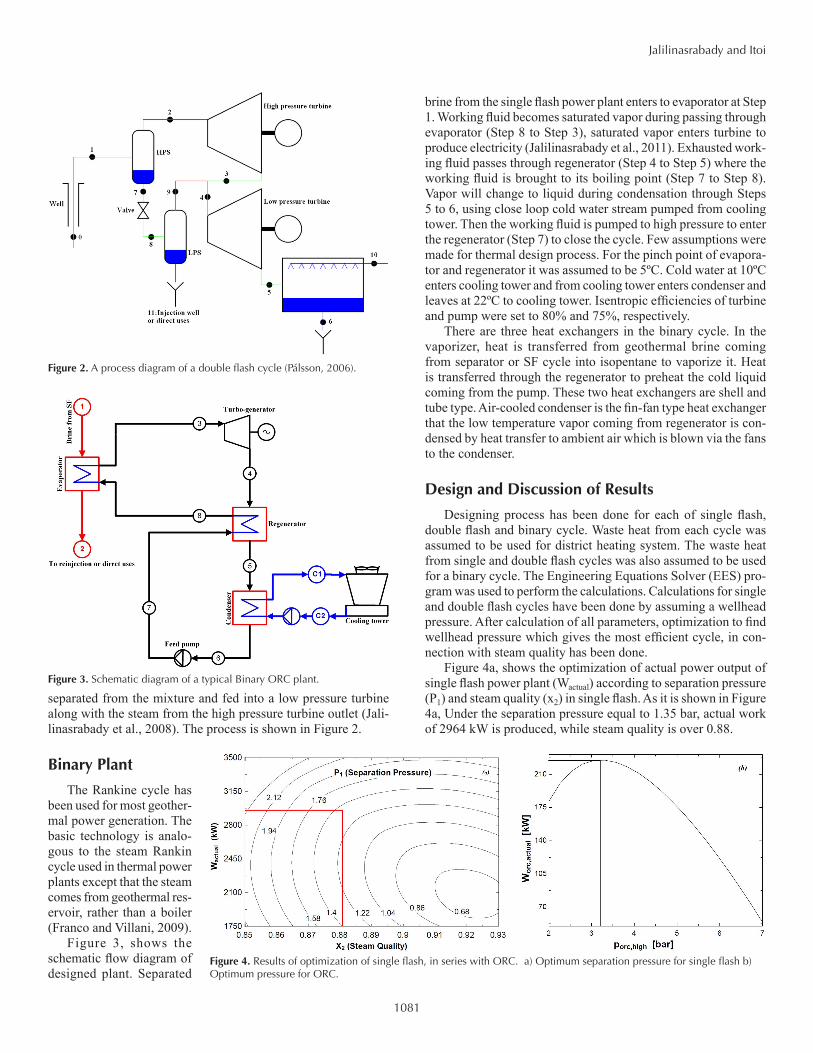
separated from the mixture and fed into a low pressure turbine along with the steam from the high pressure turbine outlet (Jali-linasrabady et al., 2008). The process is shown in Figure 2.
Binary Plant
The Rankine cycle has been used for most geother-mal power generation. The basic technology is analo-gous to the steam Rankin cycle used in thermal power plants except that the steam comes from geothermal res-ervoir, rather than a boiler (Franco and Villani, 2009).
Figure 3, shows the schematic flow diagram of designed plant. Separated
brine from the single flash power plant enters to evaporator at Step 1. Working fluid becomes saturated vapor during passing through evaporator (Step 8 to Step 3), saturated vapor enters turbine to produce electricity (Jalilinasrabady et al., 2011). Exhausted work-ing fluid passes through regenerator (Step 4 to Step 5) where the working fluid is brought to its boiling point (Step 7 to Step 8). Vapor will change to liquid during condensation through Steps 5 to 6, using close loop cold water stream pumped from cooling tower. Then the working fluid is pumped to high pressure to enter the regenerator (Step 7) to close the cycle. Few assumptions were made for thermal design process. For the pinch point of evapora-tor and regenerator it was assumed to be 5ºC. Cold water at 10ºC enters cooling tower and from cooling tower enters condenser and leaves at 22ºC to cooling tower. Isentropic efficiencies of turbine and pump were set to 80% and 75%, respectively.
There are three heat exchangers in the binary cycle. In the vaporizer, heat is transferred from geothermal brine coming from separator or SF cycle into isopentane to vaporize it. Heat is transferred through the regenerator to preheat the cold liquid coming from the pump. These two heat exchangers are shell and tube type. Air-cooled condenser is the fin-fan type heat exchanger that the low temperature vapor coming from regenerator is con-densed by heat transfer to ambient air which is blown via the fans to the condenser.
Design and Discussion of Results
Designing process has been done for each of single flash, double flash and binary cycle. Waste heat from each cycle was assumed to be used for district heating system. The waste heat from single and double flash cycles was also assumed to be used for a binary cycle. The Engineering Equations Solver (EES) pro-gram was used to perform the calculations. Calculations for single and double flash cycles have been done by assuming a wellhead pressure. After calculation of all parameters, optimization to find wellhead pressure which gives the most efficient cycle, in con-nection with steam quality has been done.
Figure 4a, shows the optimization of actual power output of single flash power plant (Wactual) according to separation pressure (P1) and steam quality (x2) in single flash. As it is shown in Figure 4a, Under the separation pressure equal to 1.35 bar, actual work of 2964 kW is produced, while steam quality is over 0.88.
Figure 2. A process diagram of a double flash cycle (Pálsson, 2006).
Figure 3. Schematic diagram of a typical Binary ORC plant.
Figure 4. Results of optimization of single flash, in series with ORC. a) Optimum separation pressure for single flash b) Optimum pressure for ORC.
1082
Jalilinasrabady and Itoi
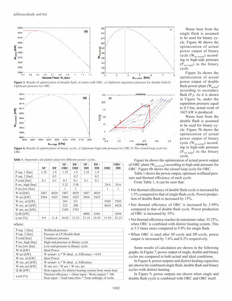
Waste heat from the single flash is assumed to be used for binary cy-cle. Figure 4b shows the optimization of actual power output of binary cycle (Worc,actual) accord-ing to high-side pressure (Porc,high) in the binary cycle.
Figure 5a shows the optimization of actual power output of double flash power plant (Wactual) according to secondary flash (P3). As it is shown in Figure 5a, under the separation pressure equal to 0.5 bar, actual work of 3425 kW is produced.
Waste heat from the double flash is assumed to be used for binary cy-cle. Figure 5b shows the optimization of actual power output of binary cycle (Worc,actual) accord-ing to high-side pressure (Porc,high) in the binary cycle.
Figure 6a shows the optimization of actual power output of ORC plant (Worc,actual) according to high-side pressure for ORC. Figure 6b shows the closed loop cycle for ORC.
Table 1 shows the power output, optimum wellhead pres-sure and thermal efficiency of each cycle.
From Table 1, it can be seen that:
• Net thermal efficiency of double flash cycle is increased by 1.5% compared to that of single flash cycle. Power produc-tion of double flash is increased by 15%.
• Net thermal efficiency of ORC is increased by 3.99% compared to that of double flash cycle. Power production of ORC is increased by 35%.
• Net thermal efficiency reaches its maximum value, 35.25%, when ORC is combined with district heating system. This is 3.5 times more compared to 9.9% for single flash.
• When ORC is used after SF-cycle and DF-cycle, power output is increased by 7.6% and 8.2% respectively.
Some results of calculation are shown in the following graphs. In Figure 7, power output of single, double and binary cycles are compared in both actual and ideal conditions.
In Figure 8, power outputs and district heating capacities are shown for combined single flash, double flash and binary cycles with district heating.
In Figure 9, power outputs are shown when single and double flash cycle is combined with ORC and ORC itself.
Figure 5. Results of optimization of double flash, in series with ORC. a) Optimum separation pressure for double flash b) Optimum pressure for ORC.
Figure 6. Results of optimization of binary cycle. a) Optimum high-side pressure for ORC b) The closed loop cycle for ORC.
Table 1. Important calculated values for different power cycles.
SF DFSF -
ORCDF - ORC
SF - DH
DF - DH ORC
ORC - DH
P sep, 1 [bar] 1.35 1.9 1.35 1.9 1.35 1.9P sep, 2 [bar] 0.5 0.5 0.5P cond [bar] 0.1 0.1 0.1 0.1 0.1 0.1P orc, high [bar] 3.32 3.58 29.6 29.6P orc,low [bar] 1 1 1 1W id [kW] 3487 4029 3487 4029 3487 4029W act [kW] 2964 3425 2964 3425 2964 3425W orc, id [kW] 265 331 5505 5505W orc, act [kW] 225 280 4624 4624W net, act [kW] 3189 3705Q dh [kW] 4000 4366 5694η net [%] 9.9 11.4 10.62 12.33 23.18 25.93 15.39 35.25
where: P sep, 1 [bar] Wellhead pressure P sep, 2 [bar] Pressure at LP-Double flashP cond [bar] Condenser pressureP orc, high [bar] High-end pressure in Binary cycle P orc,low [bar] Low-end pressure in Binary cycleW id [kW] Ideal Power W act [kW] W actual= η * W ideal , η: Efficiency = 0.85W orc, id [kW] Ideal PowerW orc, act [kW] W actual= η * W ideal , η: EfficiencyW net, act [kW] W net, act = W act + W orc, actQ dh [kW] Heat capacity for district heating system from waste heat
η net [%] Thermal efficiency = (Heat input / Work output) * 100Heat input = Total mass flow * Total enthalpy of wells

1083
Jalilinasrabady and Itoi
In Figure 10, Net thermal efficiencies and Net power outputs for different cycles and combinations are shown.
Optimization of operational parameters for SF gives power output of 2964 kW. Optimum value for separation pressure is 1.35
bar. When ORC is used in series with SF, power output is 225 kW. Optimum value for high-side pressure for ORC is 3.32 bar.
Optimization of operational parameters for DF gives power output of 3425 kW. Optimum value for separation pressure for first flash is 1.9 bar, for second flash is 0.5 bar. When ORC is used in series with DF, power output is 280 kW. Optimum value for high-side pressure for ORC is 3.7 bar.
Optimization of operational parameters for ORC gives power output of 4624 kW and internal power consumption of plant is about 236 kW. Optimum value for high-side pressure is 29 bar and low-side pressure is 10 bar.
Conclusions
The actual power output from the single flash, double flash and binary plant are 2964 kW, 3189 kW and 4624 kW respectively (Table 1). Optimum separator pressures for single and double flash are 1.35 bar and 1.9 bar/ 0.5 bar respectively. Optimum high-side pressure for ORC is 29 bar.
Comparison of power output for three cycles show that ORC cycle is more efficient from the view of power output. Also it has the highest thermal efficiency when district heating is added for heat recovery of waste heat from plant. But it doesn’t mean that it is economically preferable or not.
The output from the steam turbine increases with lower condensing pressure but so does the power consumption of the plant. Consequently, lowering the condenser pressure reduces the power plant output.
Acknowledgment
First author thanks the Japan Society for Promotion of Science (JSPS) for his scholarship.
ReferencesAustralian Renewable Energy, 2003. “Information on Single Flash Power
Plant and ORC Power Plant.” Australian Renewable Energy, internet website, http://acre.murdoch.edu.au/ago.
Figure 7. Ideal and actual power outputs of single, double and binary cycle power plants at given well parameters.
Figure 8. Power outputs of different power cycles with district heating system.
Figure 10. Net power values and Net thermal efficiency in different power cycles.
Figure 9. Power outputs of different power cycles (ORC is included after SF and DF).

1084
Jalilinasrabady and Itoi
Dincer I. and M.A. Rosen, 2007. “EXERGY, Energy, Environment and Sustainable Development.” Elsevir, ISBN: 978-0-08-044529-8, 454 pp.
Dipippo R., 2008. “Geothermal Power Plants, Second Edition: Principles, Applications, Case Studies and Environmental Impact.” Elsevier, ISBN: 978-0-7506-8620-4, 493 pp.
El-Wakil M.M., 1984. “Power Plant Technology.” McGraw-Hill, Inc, USA, 859 pp.
Franco A. and M. Villani, 2009. “A Optimal Design of Binary Cycle Power Plants for Water-dominated, Medium-temperature Geothermal Fields.” Geothermics 38, p. 379-391.
Gong, M., and G. Wall, 1997. “On exergetics, Economics and Optimization of Technical Processes to Meet Environmental Conditions.” Proceedings, Thermodynamic analysis and improvement of energy systems, Beijing, China, p. 453-460.
Jalilinasrabady S., R. Itoi, P. Valdimarsson, G. Saevarsdottir, and H. Fujii, 2012. “Flash Cycle Optimization of Sabalan Geothermal Power Plant Employing Exergy Concept”. Geothermics (2012), doi:10.1016/j.geo-thermics.2012.02.003.
Jalilinasrabady S., R. Itoi, H. Gotoh, H. Kamenosono, 2010. “Energy and Exergy Analysis of Takigami Geothermal Power Plant, Oita, Japan”. Geo-thermal Resources Council Transactions, Vol.34 2, pp.966-971. 2010a.
Jalilinasrabady S., R. Itoi, H. Fujii and T. Tanaka, 2010. “Energy and Exergy Analysis of Sabalan Geothermal Power Plant, IRAN, Pro-ceedings World Geothermal Congress 2010 , Bali, Indonesia, (25-29 April 2010). 2010b.
Jalilinasrabady S., R. Itoi, H. Gotoh, R. Yamashiro, 2011. “Exergetic Optimization of Proposed Takigami Binary Geothermal Power Plant, Oita, Japan”. Geothermal Resources Council Transactions, Vol.35 2, pp.1305-1311.
Jalilinasrabady S., P. Valdimarsson and G. Saevarsdottir, 2008. “Exergy Analysis of Double Flash Geothermal Power Plant, Sabalan, IRAN.” Proceedings, CTSI Clean Technology and Sustainable Industries Confer-ence and Trade Show, Boston, Massachusetts, (June 1-5, 2008).
Pálsson, H., 2006. “lectures on utilization of geothermal energy for power production.” University of Iceland, Iceland. Lecture notes.
Rosen, M., and I. Dincer, 2001. “Exergy as the confluence of energy, environ-ment and sustainable development.” International Journal on Exergy, 1, p. 3-13.
Valdimarsson P., 2003. “Lectures on utilization of high-temperature geother-mal resources.” UNU-GTP, Iceland, unpublished lectures.