Optimum selection of steam turbine and condenser...
6
GRC Transactions, Vol. 37, 2013 771 Keyword Geothermal power plant, Plant Performance, Condenser, Altitude, Turbine ABSTRACT Condenser is classified by heat transfer process and water level control method. The features of each type of condenser and turbine are introduced. Turbine is classified by number of casing, exhaust direction and output range and features of each type of turbine are introduced. In addition, optimum combination of each type of turbine and condenser is discussed for geothermal power plant where locates at high altitude or low altitude, comparing plant arrangement and process flow diagram in several combina- tions. In this paper, steam turbine and condenser applied to flash cycle for geothermal power plant are discussed. 1. Introduction There are many kinds of condensers which can be applied to geothermal power plant. Spray type of low level direct contact condenser is usually used for geothermal power plant because it is compact and inexpensive compared with other type of condenser, however if the power plant is located at high altitude and atmo- spheric pressure is lower than the usual, other type of condenser such as barometric direct contact condenser or surface condenser shall be considered to prevent water induction (cooling water back flowing to turbine) or to design more compact plant arrangement. If ambient temperature is so low, a compact surface condenser installed in turbine house is a good option to prevent freezing in drain lines around condenser. 2. Condenser for Geothermal Power Plant As shown in Figure 1, condensers applied to geothermal power plant are classified to direct contact and surface type. Direct contact condenser is classified to spray jet type (Figure 2) and tray type (Figure 3) and spray jet or tray type condenser is further classified to low level type and barometric type. For geothermal power plant, turbine exhaust steam is never recycled to a boiler and a direct contact condenser is usually applied. If both direct contact and surface condensers are reasonably and economically designed, performance of direct contact condenser is higher than surface condenser and the required cooling water flow rate for the same condenser pressure is smaller and non condensable gas temperature at gas cooling part exit is lower and the required size of non condensable gas extraction system can be smaller in direct contact condenser. In spray jet condenser, cooling water is sprayed by spray nozzles and condensing heat transfer occurs at the surface of the sprayed water droplets. Spray nozzle requires injection pres- sure to generate small diameter water droplets and the pressure Optimum Selection of Steam Turbine and Condenser for Geothermal Power Plant Toshiyasu Tanoguchi, Shojiro Saito, and Koji Iwai Mitsubishi Heavy Industries, Ltd., Yokohama, Japan Figure 1. Condenser Classification. Figure 2. Spray Jet Type Condenser. Figure 3. Tray Type Condenser.
Transcript of Optimum selection of steam turbine and condenser...
GRC Transactions, Vol. 37, 2013
771
KeywordGeothermal power plant, Plant Performance, Condenser, Altitude, Turbine
AbstrAct
Condenser is classified by heat transfer process and water level control method. The features of each type of condenser and turbine are introduced. Turbine is classified by number of casing, exhaust direction and output range and features of each type of turbine are introduced. In addition, optimum combination of each type of turbine and condenser is discussed for geothermal power plant where locates at high altitude or low altitude, comparing plant arrangement and process flow diagram in several combina-tions. In this paper, steam turbine and condenser applied to flash cycle for geothermal power plant are discussed.
1. Introduction
There are many kinds of condensers which can be applied to geothermal power plant. Spray type of low level direct contact condenser is usually used for geothermal power plant because it is compact and inexpensive compared with other type of condenser, however if the power plant is located at high altitude and atmo-spheric pressure is lower than the usual, other type of condenser such as barometric direct contact condenser or surface condenser shall be considered to prevent water induction (cooling water back flowing to turbine) or to design more compact plant arrangement. If ambient temperature is so low, a compact surface condenser installed in turbine house is a good option to prevent freezing in drain lines around condenser.
2. condenser for Geothermal Power Plant
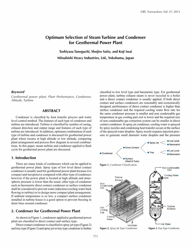
As shown in Figure 1, condensers applied to geothermal power plant are classified to direct contact and surface type.
Direct contact condenser is classified to spray jet type (Figure 2) and tray type (Figure 3) and spray jet or tray type condenser is further
classified to low level type and barometric type. For geothermal power plant, turbine exhaust steam is never recycled to a boiler and a direct contact condenser is usually applied. If both direct contact and surface condensers are reasonably and economically designed, performance of direct contact condenser is higher than surface condenser and the required cooling water flow rate for the same condenser pressure is smaller and non condensable gas temperature at gas cooling part exit is lower and the required size of non condensable gas extraction system can be smaller in direct contact condenser. In spray jet condenser, cooling water is sprayed by spray nozzles and condensing heat transfer occurs at the surface of the sprayed water droplets. Spray nozzle requires injection pres-sure to generate small diameter water droplets and the pressure
Optimum selection of steam turbine and condenser for Geothermal Power Plant
toshiyasu tanoguchi, shojiro saito, and Koji Iwai
Mitsubishi Heavy Industries, Ltd., Yokohama, Japan
Figure 1. Condenser Classification.
Figure 2. Spray Jet Type Condenser. Figure 3. Tray Type Condenser.
772
Tanoguchi, et al.
difference of atmospheric pressure and condenser pressure should cover injection pressure at spray nozzle inlet as well as pressure loss in cooling water line from cooling tower to condenser. Tray type condenser has several stages of tray which many cooling water
holes are machined at bottom plate. Water droplets are generated when cooling water in tray passes through holes and falls to lower stage tray. Tray type condenser does not require injection pressure and smaller pressure difference between atmosphere and condenser pressure is required compared with spray jet condenser and this is better for the plant located at higher altitude, however small diameter hole is sometime susceptible to clogging by foreign material or sulfide scaling. Low level condenser is installed at ground level and condenser water level is controlled by control valve at hotwell pump discharge with level controller. Barometric condenser is installed at approximately 10m high elevation and Warm water (mixture of condensate and cooling water) falls down to hot water tank situated at ground level through barometric leg. Condenser water level exists at the higher level in baromet-ric leg than the hotwell tank water level. The water level in barometric leg is deter-mined by the pressure difference between atmosphere and condenser and artificial level control system is not required. Thus, condenser water level will never increase too much in barometric condenser, and therefore there is no risk on water induc-
tion. In case of surface condenser, only steam condensate exists in condenser shell and condensate flow rate is much smaller than cooling water flow rate and there is no risk on water induction and surface condenser can be installed at the same level as turbine.
3. turbine
In this paper, condensing turbine for flash cycle is discussed. Turbine type can be categorized by number of exhaust and exhaust direction. As indicated in Figure 4, single flow, double flow or four flow design is selected considering minimum leaving loss with appropriate volumetric flow rate per an exhaust flow and appropriate loading (= mass flow rate / annual flow area) lower than the allowable.
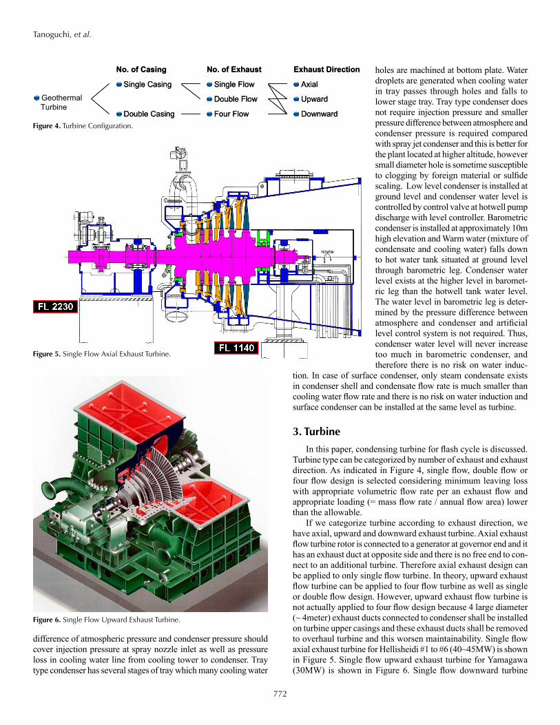
If we categorize turbine according to exhaust direction, we have axial, upward and downward exhaust turbine. Axial exhaust flow turbine rotor is connected to a generator at governor end and it has an exhaust duct at opposite side and there is no free end to con-nect to an additional turbine. Therefore axial exhaust design can be applied to only single flow turbine. In theory, upward exhaust flow turbine can be applied to four flow turbine as well as single or double flow design. However, upward exhaust flow turbine is not actually applied to four flow design because 4 large diameter (~ 4meter) exhaust ducts connected to condenser shall be installed on turbine upper casings and these exhaust ducts shall be removed to overhaul turbine and this worsen maintainability. Single flow axial exhaust turbine for Hellisheidi #1 to #6 (40~45MW) is shown in Figure 5. Single flow upward exhaust turbine for Yamagawa (30MW) is shown in Figure 6. Single flow downward turbine
Figure 5. Single Flow Axial Exhaust Turbine.
Figure 4. Turbine Configuration.
Figure 6. Single Flow Upward Exhaust Turbine.
No. of Casing
Single Casing
Double Casing
No. of Casing
Single Casing
Double Casing
No. of Exhaust
Single Flow
Double Flow
Four Flow
No. of Exhaust
Single Flow
Double Flow
Four Flow
Exhaust Direction
Axial
Upward
Downward
Exhaust Direction
Axial
Upward
Downward
Geothermal Turbine
773
Tanoguchi, et al.
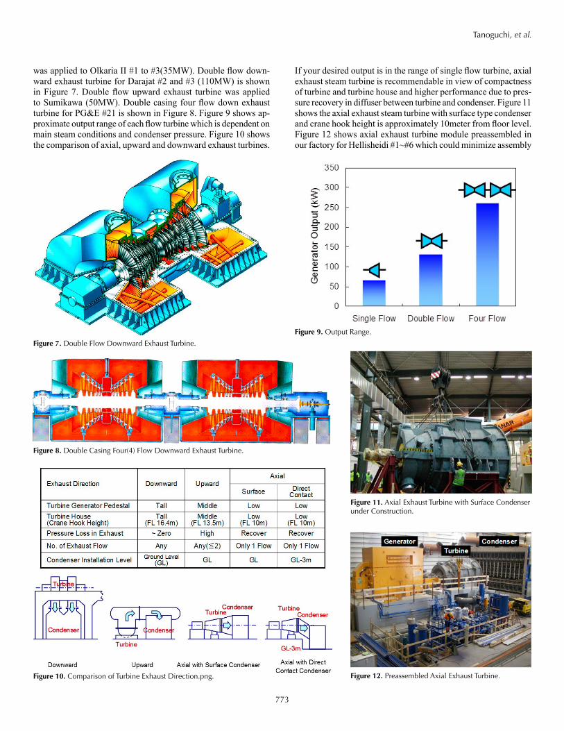
was applied to Olkaria II #1 to #3(35MW). Double flow down-ward exhaust turbine for Darajat #2 and #3 (110MW) is shown in Figure 7. Double flow upward exhaust turbine was applied to Sumikawa (50MW). Double casing four flow down exhaust turbine for PG&E #21 is shown in Figure 8. Figure 9 shows ap-proximate output range of each flow turbine which is dependent on main steam conditions and condenser pressure. Figure 10 shows the comparison of axial, upward and downward exhaust turbines.
If your desired output is in the range of single flow turbine, axial exhaust steam turbine is recommendable in view of compactness of turbine and turbine house and higher performance due to pres-sure recovery in diffuser between turbine and condenser. Figure 11 shows the axial exhaust steam turbine with surface type condenser and crane hook height is approximately 10meter from floor level. Figure 12 shows axial exhaust turbine module preassembled in our factory for Hellisheidi #1~#6 which could minimize assembly
Figure 8. Double Casing Four(4) Flow Downward Exhaust Turbine.
Figure 9. Output Range.
Figure 10. Comparison of Turbine Exhaust Direction.png.
Figure 11. Axial Exhaust Turbine with Surface Condenser under Construction.
Figure 12. Preassembled Axial Exhaust Turbine.
Figure 7. Double Flow Downward Exhaust Turbine.

774
Tanoguchi, et al.
work and the period for construction at the project site. If low bed direct contact condenser is used for axial exhaust turbine, condenser shall be installed at lower level than turbine installation level to prevent water induction. If your desired output is in the range of double flow turbine, downward or upward exhaust tur-bine shall be selected. Downward exhaust turbine is good in efficiency and maintainability because exhaust duct is not required which cause pressure loss and should be removed before turbine overhaul. However, in upward exhaust turbine case, 10meter tall turbine pedestal can be eliminated and turbine house is very compact.
4. combination of turbine and condenser
Table 1 summarizes features of each combination of turbine and condenser. If your power plant is located at low altitude, low level direct contact condenser is the most appropriate one in terms of perfor-mance and cost and this type can be combined with downward, upward or axial exhaust turbine. In case of downward or upward exhaust turbine, condenser shell works as a buffering tank against water induc-tion and condenser can be installed at the almost same level as turbine level as shown in Figure 13, how-ever condenser shell does not work as a buffering tank in case of axial exhaust turbine as shown in Figure 14 and condenser shall be installed
at lower level than turbine level. In above configurations in Figure 13 or Figure 14,
if all hotwell pumps trip, a vacuum breaker (VB) and a siphon breaker (SB) should open, and a condenser inlet valve (CIV) and non return valves (NRV) should close to suppress condenser water level elevation.
If power plant with low level direct contact con-denser is located at high altitude, it is possible that the pressure difference between atmosphere and condenser is not enough to cover pressure loss in cooling water supply line and injection pressure at spray nozzle inlet and the design water level of cooling tower basin shall be elevated (Figure 15) or condenser shall be installed at lower level. However, civil work for higher cooling tower basin or deeper pit to install condenser at lower level comes expensive and it comes difficult to design
table 1. Combination of Turbine and Condenser.
Power Plant Location Item
Downward Exhaust Turbine or Upward Exhaust Turbine Axial Exhaust Turbine
Recommendable Specification
Low altitude (lower than 3,000~4,000 meter ASL)
Condenser typeLow level direct contact Condenser shall be installed at the same elevation as turbine
Low level direct contact Condenser shall be installed at lower elevation than turbine to protect turbine from water induction
Cooling tower basin water level Same level as condenser Same level as condenser
Water induction protection
a) Non return valveb) Condenser inlet valve auto closec) Vacuum breaker valve auto opend) Siphon breaker auto open if required
a) Non return valveb) Condenser inlet valve auto closec) Vacuum breaker valve auto opend) Siphon breaker auto open if required
Hotwell pump Required RequiredCirculation water pump NOT required NOT required
Arrangement and Process Figure 5 Figure 6
High altitude (higher than 3,000~4,000 meter ASL)
Condenser Barometric direct contact Surface Barometric direct
contact Surface
Cooling tower basin water level
Lower level than condenser
Same level as condenser
Lower level than condenser
Same level as condenser
Water induction protection Not required Not required Not required Not required
Hotwell or con-densate pump Required Required Required Required
Circulation water pump Required Required Required Required
Arrangement and Process Figure 8 – – Figure 9
Figure 13. Upward Exhaust Turbine with Low Level Direct Contact Condenser at Low Altitude.
Figure 14. Axial Exhaust Turbine with Low Level Direct Contact Condenser at Low Alti-tude.

775
Tanoguchi, et al.
protection system to prevent water induction if the water level of cooling tower basin is very high. This is the reason why it is better to apply barometric condenser or surface condenser in case that power plant is located at high altitude as shown in Figure 16 and Figure 17.
Above discussion was made based on that plant area is flat, however if the power plant is on slope land, we can utilize the slope as an example shown in Figure 18. In case that we apply barometric condenser at flat land, condenser shall be installed at elevated level supported by steel structure as shown in Figure 16 but in case of slope land, we can install barometric condenser at the same level as turbine level by installing hot well tank at lower elevation, eliminating the steel structure as shown in Figure 18.
If your plant locates at high altitude and atmospheric tempera-ture is very low, surface condenser installed in a turbine house is a good option to consider because freeze around condenser is effectively prevented as shown in Figure 11.
5. conclusions
In this paper, we discussed the optimum combination of each type of turbine and condenser for geothermal power plant. Axial exhaust turbine has only one exhaust flow and output is limited to approximately 60MW which depends on the main steam condition or condenser pressure. If your planned output is less than 60MW, axial exhaust turbine is the best option in view of the compactness of turbine house and turbine efficiency.
In case of axial exhaust turbine, only a part of the condenser shell volume can be used as a buffering tank to protect turbine from water induction and condenser should be installed at lower elevation than turbine.
If your project site is located at very high altitude, atmospheric pressure is lower, cooling tower should be installed at much higher elevation than condenser to keep condenser nozzle injection pres-sure and this means that the level difference between a cooling tower and a turbine is not enough and the risk on water induction comes high. In this case, barometric condenser or surface con-denser is also good option.
references
Obana, H., 2011. Heat exchanger design hand book, Kogaku Tosho
Saito, S. et al., 2010. Introduction to the features and technology of geother-mal power plants which contribute to the prevention of global warming, Mitsubishi Heavy Industries, Ltd Technical Review Vol.47 No.1
Saito, S. et al., 2008. How geothermal power plants help to reduce CO2 emis-sion, Mitsubishi Heavy Industries, Ltd. Technical Review, Vol.45 No.1
Saito, S., 2010. Technologies for high performance and reliability of geo-thermal power plant, Proceeding World Geothermal Congress 2010 Bali, Indonesia
Fukuda, H. et al., 2009. Development of 3,600-rpm 50-inch/3,000-rpm 60-inch ultra-long exhaust end blades, Mitsubishi Heavy Industries, Ltd. Technical Review Vol. 46 No.2
Watanabe, E. et al., 2003. Development of new high efficiency steam turbine, Mitsubishi Heavy Industries, Ltd. Technical Review Vol. 40 No.4
Watanabe, E. et al., 2001. Development of new advanced low pressure end blades for high efficiency steam turbine, Icope p.862
Figure 15 . Upward Exhaust Turbine with Low Level Direct Contact Con-denser at High Altitude.
Figure 17. Axial Exhaust Turbine with Surface Condenser at High Altitude.
Figure 16. Upward Exhaust Turbine with Barometric Condenser at High Altitude Flat Land.
Figure 18. Upward Exhaust Turbine with Barometric Condenser at High Altitude Slope Land.

776