Surface Detail and Non-PhotoRealistic Rendering Lecture 3 (Rendering)

To appear in Proceedings SPIE EI 2004, San Jose, CA
Fast Dynamic Flow Volume Rendering Using Textured Splats on Modern Graphics Hardware
Daqing Xue and Roger Crawfis1
The Ohio State University, 2015 Neil Avenue, Columbus, OH 43210, USA
ABSTRACT
Dynamic flow volume rendering of three-dimensional vector fields offers better insights into the continuum and dynamics of the data field under investigation. Consumer graphics cards have seen a rapid explosion of performance and capabilities over the past few years. This paper explores the development of the Textured Splats algorithm for direct flow volume rendering of vector fields, that utilizes this new hardware. This paper presents the technique using new hardware that supports vertex programs, OpenGL multi-textures and register combiner extensions to implement fast dynamic flow volume rendering on a PC. Several anisotropic textured splats are investigated to implement flow volume rendering.
Keywords: Dynamic Flow Volume Rendering, Textured Splats, Graphics Hardware
1. INTRODUCTION
Over the years, many computer graphics researchers have developed accelerated splatting algorithms [1] [2] using 2D texture mapping hardware for scalar and vector field volumetric datasets. Interactive rates are only achievable with rather small datasets. In recent years, with the development of advanced graphics cards, it is worthwhile to develop a more efficient texture splatting algorithm for interactive and dynamical flow volume rendering.
For many data sets, an analytical back-to-front sort can be solved by using redundant pre-sorted lists [3]. However, due to the very high rasterization performance of modern graphics hardware the GPU is idle most of the time in an immediate-mode rendering pipeline. Crawfis and Max [2] explore anisotropic textured splats to represent multi-variate vector fields by using a large set of textures adding different length vector icons to the reconstruction kernel texture. King et al. [4] and Wei et al. [5] develop another set of textured splats with gaseous details to represent amorphous volumes like fire. They both generate a table of textures with different phase-shifts to achieve animation for vector fields and gaseous volumes. In OpenGL, hardware accelerated splatting for vector fields is achieved with the following steps:
1) Create a texture image from the reconstruction kernel function as the splat footprint; 2) Create a set of anisotropic textures for the vector field, fire or smoke rendering; 3) Create a quadrilateral which is centered about the voxel location for each voxel in the volume; 4) Sort all voxels along the view direction; 5) Reorient each voxel quadrilateral to be perpendicular to the viewing ray; 6) Select the appropriate texture based upon the vector field direction at the current voxel; 7) Render the quads with texture mapping in a back-to-front order.
In this paper, we present a dynamic, multi-glyphic textured splatting technique to render multi-variate flow volumes with the support of vertex shaders on graphics hardware. We implement a vertex program, using the OpenGL multi-texture and register combiner extensions to construct anisotropic textured splats, which can represent vector fields, and to dynamically visualize the flow volume. We achieve the animation effect in a very efficient way, while using only one or two small textures. In addition, we provide multi-glyphic textured splats to classify and visualize the vector field.
The remainder of this paper is organized as follows. Section 2 describes the idea of textured splats and how to implement them on hardware. In section 3, we briefly examine the vertex shader and provide the work flow in this
1 Further author information: (Send correspondence to D.X.) D.X.: E-mail: [email protected], Telephone: 1 614 688 3862 R.C.: E-mail: [email protected], Telephone: 1 614 292 2566

To appear in Proceedings SPIE EI 2004, San Jose, CA
vertex shader. The resulting images and performance are presented in section 4. In section 5 we offer conclusions from our study.
2. TEXTURED SPLATS
For vector field representations, we embed directional icons or glyphs into the texture used for the footprint integration [1][6][11]. Two textures, one for the scalar kernel map and one for anisotropic vector icons, are generated with only an alpha channel. To represent the vector field correctly, the quadrilateral splat must be rotated according to its vector field direction in eye space. The view-dependent reorientation of the splat is performed in the vertex program of vertex shader [9], which will be discussed in the next section. This adds an additional complexity to the vertex program, since the transformation and lighting stage of the OpenGL pipeline is bypassed [7]. The splat is then rotated according to its projected vector direction in eye space, such that the mapped anisotropic vector icon aligns with its projected vector direction.
Several additional problems addressed by [2] need to be solved. Specifically, we investigate vector field animation, multi-variate color-coding of the vector icons and multi-glyphic textured splats, and vector icon foreshortening due to its projection on the plane orthogonal to the view direction.
2.1. Multi-Variate and Multi-Glyphic Textured Splats
Representing data sets with both scalar values and vector icons offers us more cues and insights about the relationship between these fields. This was also supported in [2]. Figure 1 shows an image reprinted from that paper, where the percent cloudiness is rendered using a traditional scalar field volume renderer via splatting, and the wind velocity is rendered using the textured splats icons. Here, the vector icons are color-coded by an independent variable. In this case, the altitude was used to provide additional positional information. To accomplish this, we use a BLEND operator to create a splat’s color as a dissolve between the quad color ),,( pripripri BGR and a vector icon secondary
color ),,( secsecsec BGR . The splat’s resulting color is thus:
))*)1((*
*)1(*
*)1(*
*)1(*
101
1sec1
1sec1
1sec1
textextexpri
textexpri
textexpri
textexpri
AAAAA
ABABB
AGAGG
ARARR
+−=
+−=
+−=
+−=
Here, 0texA , 1texA are the alpha channels of the reconstruction kernel texture and the vector icon texture, respectively. The splat’s color is then attenuated by its opacity and composited into the final image with the blending function glBlendFunc(GL_SRC_ALPHA, GL_ONE_MINUS_SRC_ALPHA) in a back-to-front rendering order [12][13].
Figure 1: Percent cloudiness and wind velocities. The wind velocities are color coded by altitude. Courtesy of Roger Crawfis.

To appear in Proceedings SPIE EI 2004, San Jose, CA
Figure 2 shows the blending operation between the two textures used by the hardware [8]. Both the reconstruction kernel map and the vector icon are generated as only one channel (alpha channel) textures and they are assigned as texture unit 0 and texture unit 1 respectively. The primary color is assigned using the voxel intensity with a proper transfer function, while the secondary color is assigned as the vector icon color. Figure 2 demonstrates the register combiner diagram to compute the splat’s color and opacity. Its final color (modulated by its opacity) is also presented at the bottom right.
In the above discussion, we use color to code the vector tensor. To obtain better insight of vector fields, we can use different vector icon textures to represent the flow in the same volume rendering (multi-glyphic textured splats). Each textured splat is associated with a specific vector icon texture; the splat will be mapped with this texture during rasterization and presents the visual property of its vector icon texture.
The vector glyph accounts for the final image rendered from the flow volume. We explore four vector glyphs: stroked lines, stream lines, particles, and arrows. The first three are demonstrated as the insets in figure 3a, 3b, and 3c. The last (arrows) are demonstrated in figure 6. Figure 3a, 3b, 3c shows the vectors in the core part of the test dummy dataset [2] are rendered with stroked line, stream line, and particle glyphs, respectively. Figure 3d shows the application of multi-glyphic texture splats. The vectors with different tensorial values are mapped with different vector glyphs.
2.2. Foreshortening of the vector icons
To represent the vector direction more accurately, we must foreshorten the anisotropic vector icons inversely-proportional to their projected length on the x-y plane in eye space. This provides long vector icons when the flow is parallel to the viewing plane, and short vector icons when the flow is either headed towards the eye or away from it. Two plausible solutions for this are that we either rotate the textured splat such that it is always parallel to the vector field direction or that we simply shorten the quadrilateral geometry in the projected vector field direction. Unfortunately, neither method works for multi-variate vector fields, where the scalar reconstruction kernel needs to be preserved. Crawfis and Max [2] built a table containing the vector icon textures with different lengths. The z component, vz, of the vector direction in eye space is used to index into the table. This again, required several repeated textures and wasted a large amount of texture memory. Our alternative is to shrink the vector texture by changing the texture mapping coordinates. It foreshortens the vector icon length by increasing its occurrence frequency. This foreshortening is view-dependent and hence, precludes any efficient strategy for calculating the texture coordinates and saving them in a display list or vertex array. Fortunately, we can modify the texture mapping coordinates in the vertex program to implement this method. Since the vector icon texture is separate from the reconstruction kernel texture, we can treat their texture coordinates separately as well. For the normalized vector direction, we interpolate the output texture coordinate, output_xtex1, on the x-axis from the following equation:
=
==
0_0
1_),/1min(
_
1
1max
1
tex
tex
tex
xinputif
xinputiffd
xoutput
Texture unit 0
A
B
C
D
AB
Spare 0
ALPHA portion
A
B
C
D
AB+CD
Spare 0
ALPHA portion
A RGB
RGB A
A
B
C
D
AB+(1-A)C+D
RGB portion
ZERO
RGB A
A RGB
Texture unit 1 RGB
Secondary color
Primary color
Combiner0 Combiner1 Final Combiner
A
1-A
A
RGB RGB A A
A
Output fragment
Figure 2: the register combiner diagram for producing the splat color using our BLEND equation.

To appear in Proceedings SPIE EI 2004, San Jose, CA
Here, d is the projection length of the vector direction on the x-y plane and fmax is the maximum occurrence frequency of the icon. To prevent from producing an infinite number of vector icons when d approaches 0, the output x-coordinate is limited to fmax , or no more than fmax copies of the vector icon texture mapped to the same splat quadrilateral. There is no foreshortening for the vector icon if the projection length d is one, while the shortened vector icon repeats fmax times in the x-axis direction if d is equal to or smaller than 1/fmax. According to our numerical experiments, the maximum occurrence of fmax=3 delivers a satisfactory visualization. We use normalized vectors to show the direction only, relying on other techniques to show the magnitude.
2.3. Dynamic Representation
Animation can be achieved by using a phase-shift through the overlapping vector icon textures [2]. Crawfis and Max [2] developed a set of textures and cycled through these textures to achieve the animation. Each texture was a cyclical shift of the vector icon in the negative flow direction represented by the texture. This presented problems in that all textured splats either had to move at the same speed, or a slight pause could be introduced to delay the texture movement and discrete jumps were made. These discrete jumps can be mitigated by using a larger set of textures, but at the cost of additional texture memory. Here, we have been able to reduce this to the use of only a single vector icon texture. To obtain the illusion of coherent motion, we design a vector icon texture that is cyclically in the desired flow direction (we use the x-axis as the primary direction) and shift the texture coordinates in this direction for each time stamp. For this to be successful, the texture needs to be windowed, such that there are no hard edges. Crawfis and Max [2] used a larger Gaussian window to smoothly have the textures become transparent. This windowing was applied after they phase shifted the texture pattern and was pre-computed and stored with the set of textures. Applying this window to our phase
(a) (b)
(c) (d)
Figure 3: The dummy test tornado dataset [2]. The tornado core is rendered with the inset vector icon texture in (a)(b)(c), respectively. The full dataset is rendered with 3 different icon texture (strokes, lines, and particles) corresponding to different velocity magnitudes. The animation files are at http://www.cis.ohio-state.edu/~xue/research/vda04.

To appear in Proceedings SPIE EI 2004, San Jose, CA
shifted texture icons requires the opacity mask for the window to remain fixed on the textured quad. We only shift the vector icon texture coordinates along the desired direction in the vertex program. This requires separate textures, one for the reconstruction kernel, which also serves as the vector icon windowing mask, and one for the vector icon. These are then combined by the register combiners. This could not be achieved with OpenGL 1.1 due to the limited texture combiner functions available. Figure 5 shows a 2×2 tiling of the stroked vector icon texture. There is no seam between the adjacent textures. We consider an infinite texture created from these tilings, from which we roam through to produce the animation. The vector icon texture is shifted for each time stamp and then windowed while keeping the reconstruction texture untouched.
Figure 5: 2×2 periods of the vector icon textures
Figure 4 shows the vortex part of the dummy test tornado dataset at four successive time steps in the four top images. The framed regions demonstrate the shift of the vector icons. The four bottom images are the shifted vector icon texture.
Unlike the static representation of the vector field like color or multi-glyphic texture, we map the velocity magnitude into the phase-shift step in the vertex program. The vector icons with different velocity magnitudes will move at their own speeds. This gives us more intuitive understanding of the vector field.
3. VERTEX SHADER
To achieve volume rendering using 2D texture mapping hardware, we use a billboard technique [10] to orient splats whenever the view direction change, such that the splats always face toward the viewer. The OpenGL 1.4 ARB vertex shader provides a vertex program to perform per-vertex operation, including the vertex transformation [7][9]. To gain the interactive rendering rate, we also need to avoid the overhead associated with per-splat computations on the CPU. To accomplish this, we need to specify the vector field direction for each voxel. The coordinates of the quadrilateral splat and the vector direction are first transformed into eye space. The rotation matrix in eye space is constructed to orient the textured icons aligned with the projected vector direction. The coordinates of the quadrilateral are then re-rotated to lie parallel to the screen. The pseudo code for the vertex program is as following:
1) Transform vector direction from object space into eye space; 2) Construct rotation matrix from the model view matrix;
Figure 4: The close-up view of the vortex from figure 3(a). The framed regions in the top image show the shift of the vector icon on the tornado at the four successive time stamps. The bottom images show the corresponding shift of the vector icon texture.
To appear in Proceedings SPIE EI 2004, San Jose, CA
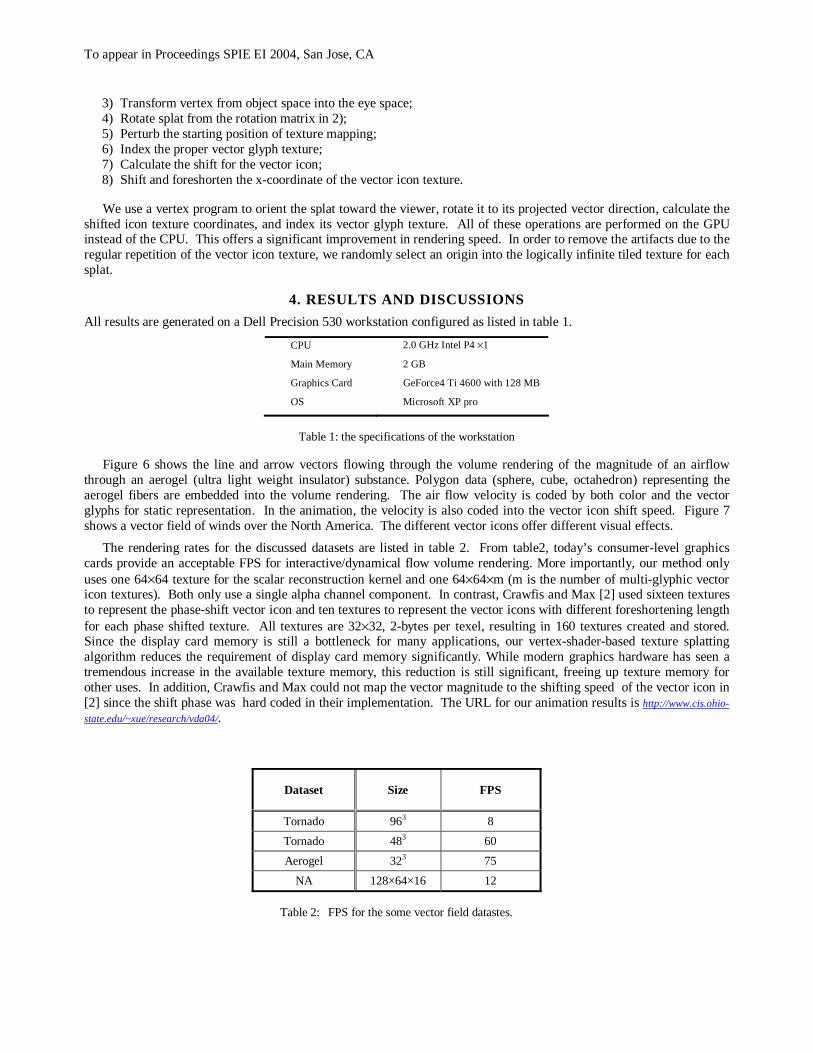
3) Transform vertex from object space into the eye space; 4) Rotate splat from the rotation matrix in 2); 5) Perturb the starting position of texture mapping; 6) Index the proper vector glyph texture; 7) Calculate the shift for the vector icon; 8) Shift and foreshorten the x-coordinate of the vector icon texture.
We use a vertex program to orient the splat toward the viewer, rotate it to its projected vector direction, calculate the
shifted icon texture coordinates, and index its vector glyph texture. All of these operations are performed on the GPU instead of the CPU. This offers a significant improvement in rendering speed. In order to remove the artifacts due to the regular repetition of the vector icon texture, we randomly select an origin into the logically infinite tiled texture for each splat.
4. RESULTS AND DISCUSSIONS
All results are generated on a Dell Precision 530 workstation configured as listed in table 1.
CPU 2.0 GHz Intel P4 ×1
Main Memory 2 GB
Graphics Card GeForce4 Ti 4600 with 128 MB
OS Microsoft XP pro
Table 1: the specifications of the workstation
Figure 6 shows the line and arrow vectors flowing through the volume rendering of the magnitude of an airflow through an aerogel (ultra light weight insulator) substance. Polygon data (sphere, cube, octahedron) representing the aerogel fibers are embedded into the volume rendering. The air flow velocity is coded by both color and the vector glyphs for static representation. In the animation, the velocity is also coded into the vector icon shift speed. Figure 7 shows a vector field of winds over the North America. The different vector icons offer different visual effects.
The rendering rates for the discussed datasets are listed in table 2. From table2, today’s consumer-level graphics cards provide an acceptable FPS for interactive/dynamical flow volume rendering. More importantly, our method only uses one 64×64 texture for the scalar reconstruction kernel and one 64×64×m (m is the number of multi-glyphic vector icon textures). Both only use a single alpha channel component. In contrast, Crawfis and Max [2] used sixteen textures to represent the phase-shift vector icon and ten textures to represent the vector icons with different foreshortening length for each phase shifted texture. All textures are 32×32, 2-bytes per texel, resulting in 160 textures created and stored. Since the display card memory is still a bottleneck for many applications, our vertex-shader-based texture splatting algorithm reduces the requirement of display card memory significantly. While modern graphics hardware has seen a tremendous increase in the available texture memory, this reduction is still significant, freeing up texture memory for other uses. In addition, Crawfis and Max could not map the vector magnitude to the shifting speed of the vector icon in [2] since the shift phase was hard coded in their implementation. The URL for our animation results is http://www.cis.ohio-
state.edu/~xue/research/vda04/.
Dataset Size FPS
Tornado 963 8
Tornado 483 60
Aerogel 323 75
NA 128×64×16 12
Table 2: FPS for the some vector field datastes.

To appear in Proceedings SPIE EI 2004, San Jose, CA
5. CONCLUSION
We visualize the flows statically and dynamically. The vector field is both coded into color and/or vector glyphs for static representation and mapped to the glyph shifting step for dynamical representation. Our multi-glyphic vector icons and dynamical rendering provide more cues and insights to understand flows. In addition, modern graphics hardware provides many advanced features, such as vertex programming, multi-texture, and register combiners, which are very powerful toward implement textured splatting and offer a significant performance improvement. Interactive dynamic flow volume rendering for fairly complex volumetric datasets on consumer-level graphics cards is now feasible.
REFERENCES
1. D. Laur, P. Hanrahan, “Hierarchical Splatting: A Progressive Refinement Algorithm for Volume Rendering,”
SIGGRAPH’91, pp. 285-288, 1991. 2. R. Crawfis, N. Max, “Texture Splats for 3D Vector and Scalar Field Visualization,” Proc. Visualization’93, IEEE
CS Press, pp. 261-266, Los Alamitos, 1993. 3. I. Ihm and R. K. Lee, "On Enhancing the Speed of Splatting with Indexing." IEEE Visualization 1995, Alanta,
GA, 69-76. 4. S. King, R. Crawfis and W. Reid, “Fast Animation of Amorphous and Gaseous Volumes,” Volume Graphics '99,
Swansea, UK, pp. 336-346. 5. X. Wei, W. Li, K. Mueller, and A. Kaufman, “Simulating Fire with Texture Splats,” IEEE Visualization 2002, pp.
227-237, Boston, MA. 6. L. A. Westover, “Footprint Evaluation for Volume Rendering”, Computer Graphics (Proceedings of SIGGRAPH),
24(4), August 1990, pp. 367–376. 7. E. Lindholm, M. J. Kilgard, and H. Moreton, “A User-Programmable Vertex Engine,” SIGGRAPH’01, pp. 12-17,
2001. 8. J. Spitzer, “Texture Compositing With Register Combiners Compositing With Register Combiners,”
http://developer.nvidia.com/. 9. C. Wynn, “OpenGL Vertex Programming on Future-Generation GPUs,” http://developer.nvidia.com/.
10. http://www.lighthouse3d.com/opengl/billboarding/ 11. L. Westover, “Interactive volume rendering,” Proceedings of the Chapel Hill Workshop on Volume Visualization,
Chapel Hill, NC, May, 1989. 12. M. Meißner, J. Huang, D. Bartz, K. Muller, R. Crawfis, “A Practical Evaluation of Popular Volume Rendering
Algorithms,” Proc. of Volume Vis. Sym., 2000. 13. N. Max, “Optical model for direct volume rendering,” IEEE Trans. Vis. and Comp. Graph., vol. 1, no. 2, pp. 99-
108, 1995.

To appear in Proceedings SPIE EI 2004, San Jose, CA
Figure 7: Wind on North America dataset. The left images are generated with their right texture icons, respectively. The velocity is coded by the vector icon color. The animation files are at http://www.cis.ohio-state.edu/~xue/research/vda04.
Figure 6: The image is rendered from aerogel dataset with two vector glyphs (lines, arrows). The vector field is coded not only by its color but also by the vector glyphs. The animation file is at http://www.cis.ohio-state.edu/~xue/research/vda04.