PDA1500 - literature.puertoricosupplier.comliterature.puertoricosupplier.com/087/WD87064.pdf ·...
6
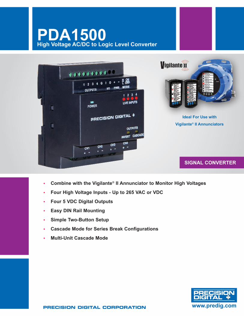
• Combine with the Vigilante ® II Annunciator to Monitor High Voltages • Four High Voltage Inputs - Up to 265 VAC or VDC • Four 5 VDC Digital Outputs • Easy DIN Rail Mounting • Simple Two-Button Setup • Cascade Mode for Series Break Configurations • Multi-Unit Cascade Mode SIGNAL CONVERTER PDA1500 High Voltage AC/DC to Logic Level Converter PRECISION DIGITAL CORPORATION www.predig.com Ideal For Use with Vigilante ® II Annunciators
Transcript of PDA1500 - literature.puertoricosupplier.comliterature.puertoricosupplier.com/087/WD87064.pdf ·...
• CombinewiththeVigilante®IIAnnunciatortoMonitorHighVoltages
• FourHighVoltageInputs-Upto265VACorVDC
• Four5VDCDigitalOutputs
• EasyDINRailMounting
• SimpleTwo-ButtonSetup
• CascadeModeforSeriesBreakConfigurations
• Multi-UnitCascadeMode
SIGNALCONVERTER
PDA1500HighVoltageAC/DCtoLogicLevelConverter
Precision Digital corPoration www.predig.com
IdealForUsewith
Vigilante®IIAnnunciators
www.predig.com2
PDA1500HighVoltageAC/DCtoLogicLevelConverter
INTRODUCTIONThe PDA1500 High VAC/VDC to Logic Level Converter is an easy to use DIN rail mounted device for converting high voltage signals into logic level signals for use as a digital input to a wide range of process control and display equipment.
The PDA1500 accepts up to four high voltage AC or DC signals. The PDA1500-115 inputs accept 85-130 VAC or VDC, and the PDA1500-230 inputs accept 185-265 VAC or VDC. Powered from 12-24 VDC, the PDA1500 can drive outputs even when no high voltage inputs are present. The outputs are user selectable for high or low states when voltage is present at the inputs.
Cascade mode is ideal for monitoring signals that can result in cascading or subsequent failures. This mode monitors the point of failure, when a failure in a single input causes a failure in all alarm points in a “series” system.
The PDA1500 is mounted in an ABS plastic DIN rail mounted enclosure for easy mounting inside a panel or instrument enclosure.
DINRAILMOUNTINGThe converter requires a length of 35 mm “top hat” DIN rail 3.00” (76.3 mm) wide.
The converter may be installed between other equipment on the same DIN rail without removing the other equipment.
Clearance: allow at least 1.0” (25.4 mm) clearance above and below the PDA1500 on the installation back-panel for wiring.
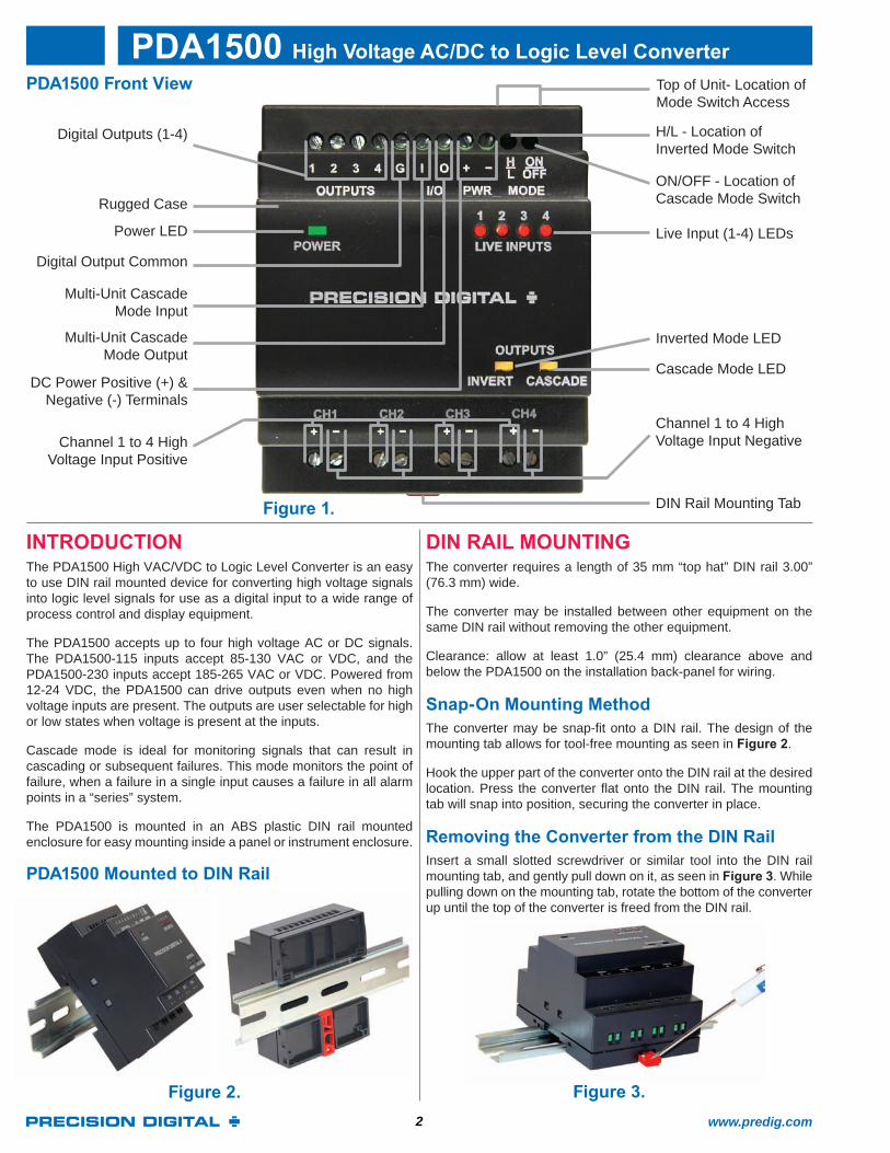
Snap-OnMountingMethodThe converter may be snap-fit onto a DIN rail. The design of the mounting tab allows for tool-free mounting as seen in Figure2.
Hook the upper part of the converter onto the DIN rail at the desired location. Press the converter flat onto the DIN rail. The mounting tab will snap into position, securing the converter in place.
RemovingtheConverterfromtheDINRailInsert a small slotted screwdriver or similar tool into the DIN rail mounting tab, and gently pull down on it, as seen in Figure3. While pulling down on the mounting tab, rotate the bottom of the converter up until the top of the converter is freed from the DIN rail.
Power LED
Digital Outputs (1-4)
Rugged Case
Channel 1 to 4 High Voltage Input Positive
Digital Output Common
Multi-Unit Cascade Mode Input
DC Power Positive (+) & Negative (-) Terminals
Multi-Unit Cascade Mode Output
H/L - Location of Inverted Mode Switch
ON/OFF - Location of Cascade Mode Switch
Live Input (1-4) LEDs
Inverted Mode LED
Cascade Mode LED
Channel 1 to 4 High Voltage Input Negative
DIN Rail Mounting Tab
PDA1500FrontView Top of Unit- Location of Mode Switch Access
Figure1.
Figure2.
PDA1500MountedtoDINRail
Figure3.
www.predig.com3
PDA1500HighVoltageAC/DCtoLogicLevelConverter
OPERATIONThe PDA1500 High Voltage AC/DC to Logic Level Converter accepts up to four high voltage input signals and outputs a TTL logic (5 V) signal representative of each input’s status, whether high voltage is present or not.
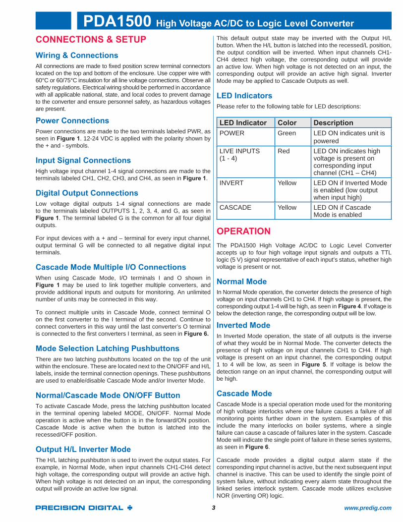
NormalModeIn Normal Mode operation, the converter detects the presence of high voltage on input channels CH1 to CH4. If high voltage is present, the corresponding output 1-4 will be high, as seen in Figure4. If voltage is below the detection range, the corresponding output will be low.
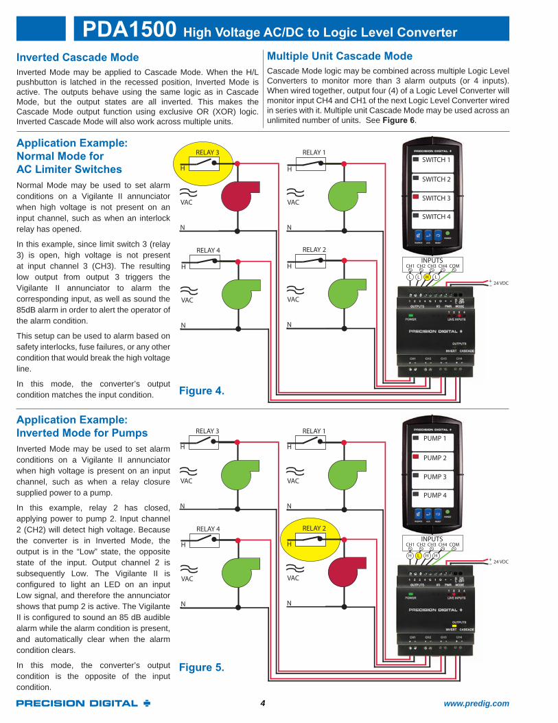
InvertedModeIn Inverted Mode operation, the state of all outputs is the inverse of what they would be in Normal Mode. The converter detects the presence of high voltage on input channels CH1 to CH4. If high voltage is present on an input channel, the corresponding output 1 to 4 will be low, as seen in Figure 5. If voltage is below the detection range on an input channel, the corresponding output will be high.
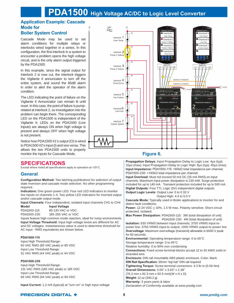
CascadeModeCascade Mode is a special operation mode used for the monitoring of high voltage interlocks where one failure causes a failure of all monitoring points further down in the system. Examples of this include the many interlocks on boiler systems, where a single failure can cause a cascade of failures later in the system. Cascade Mode will indicate the single point of failure in these series systems, as seen in Figure6.
Cascade mode provides a digital output alarm state if the corresponding input channel is active, but the next subsequent input channel is inactive. This can be used to identify the single point of system failure, without indicating every alarm state throughout the linked series interlock system. Cascade mode utilizes exclusive NOR (inverting OR) logic.
CONNECTIONS&SETUPWiring&ConnectionsAll connections are made to fixed position screw terminal connectors located on the top and bottom of the enclosure. Use copper wire with 60°C or 60/75°C insulation for all line voltage connections. Observe all safety regulations. Electrical wiring should be performed in accordance with all applicable national, state, and local codes to prevent damage to the converter and ensure personnel safety, as hazardous voltages are present.
PowerConnectionsPower connections are made to the two terminals labeled PWR, as seen in Figure1. 12-24 VDC is applied with the polarity shown by the + and - symbols.
InputSignalConnectionsHigh voltage input channel 1-4 signal connections are made to the terminals labeled CH1, CH2, CH3, and CH4, as seen in Figure1.
DigitalOutputConnectionsLow voltage digital outputs 1-4 signal connections are made to the terminals labeled OUTPUTS 1, 2, 3, 4, and G, as seen in Figure1. The terminal labeled G is the common for all four digital outputs.
For input devices with a + and – terminal for every input channel, output terminal G will be connected to all negative digital input terminals.
CascadeModeMultipleI/OConnectionsWhen using Cascade Mode, I/O terminals I and O shown in Figure 1 may be used to link together multiple converters, and provide additional inputs and outputs for monitoring. An unlimited number of units may be connected in this way.
To connect multiple units in Cascade Mode, connect terminal O on the first converter to the I terminal of the second. Continue to connect converters in this way until the last converter’s O terminal is connected to the first converters I terminal, as seen in Figure6.
ModeSelectionLatchingPushbuttonsThere are two latching pushbuttons located on the top of the unit within the enclosure. These are located next to the ON/OFF and H/L labels, inside the terminal connection openings. These pushbuttons are used to enable/disable Cascade Mode and/or Inverter Mode.
Normal/CascadeModeON/OFFButtonTo activate Cascade Mode, press the latching pushbutton located in the terminal opening labeled MODE, ON/OFF. Normal Mode operation is active when the button is in the forward/ON position. Cascade Mode is active when the button is latched into the recessed/OFF position.
OutputH/LInverterModeThe H/L latching pushbutton is used to invert the output states. For example, in Normal Mode, when input channels CH1-CH4 detect high voltage, the corresponding output will provide an active high. When high voltage is not detected on an input, the corresponding output will provide an active low signal.
This default output state may be inverted with the Output H/L button. When the H/L button is latched into the recessed/L position, the output condition will be inverted. When input channels CH1-CH4 detect high voltage, the corresponding output will provide an active low. When high voltage is not detected on an input, the corresponding output will provide an active high signal. Inverter Mode may be applied to Cascade Outputs as well.
LEDIndicatorsPlease refer to the following table for LED descriptions:
LEDIndicator Color DescriptionPOWER Green LED ON indicates unit is
poweredLIVE INPUTS(1 - 4)
Red LED ON indicates high voltage is present on corresponding input channel (CH1 – CH4)
INVERT Yellow LED ON if Inverted Mode is enabled (low output when input high)
CASCADE Yellow LED ON if Cascade Mode is enabled
www.predig.com4
PDA1500HighVoltageAC/DCtoLogicLevelConverterInvertedCascadeModeInverted Mode may be applied to Cascade Mode. When the H/L pushbutton is latched in the recessed position, Inverted Mode is active. The outputs behave using the same logic as in Cascade Mode, but the output states are all inverted. This makes the Cascade Mode output function using exclusive OR (XOR) logic. Inverted Cascade Mode will also work across multiple units.
MultipleUnitCascadeModeCascade Mode logic may be combined across multiple Logic Level Converters to monitor more than 3 alarm outputs (or 4 inputs). When wired together, output four (4) of a Logic Level Converter will monitor input CH4 and CH1 of the next Logic Level Converter wired in series with it. Multiple unit Cascade Mode may be used across an unlimited number of units. See Figure6.
PUMP 1
PUMP 2
PUMP 3
PUMP 4
INPUTSCH1 CH2 CH3 CH4 COM
VAC
H
N
RELAY 1
VAC
H
N
RELAY 2
VAC
H
N
RELAY 3
VAC
H
N
RELAY 4
H HHL+- 24 VDC
ApplicationExample:InvertedModeforPumpsInverted Mode may be used to set alarm conditions on a Vigilante II annunciator when high voltage is present on an input channel, such as when a relay closure supplied power to a pump.
In this example, relay 2 has closed, applying power to pump 2. Input channel 2 (CH2) will detect high voltage. Because the converter is in Inverted Mode, the output is in the “Low” state, the opposite state of the input. Output channel 2 is subsequently Low. The Vigilante II is configured to light an LED on an input Low signal, and therefore the annunciator shows that pump 2 is active. The Vigilante II is configured to sound an 85 dB audible alarm while the alarm condition is present, and automatically clear when the alarm condition clears.
In this mode, the converter’s output condition is the opposite of the input condition.
SWITCH 1
SWITCH 2
SWITCH 3
SWITCH 4
INPUTSCH1 CH2 CH3 CH4 COM
VAC
N
RELAY 1
H
VAC
H
N
RELAY 2
N
VAC
H
RELAY 3
VAC
N
RELAY 4
H
+- 24 VDC
L LHL
ApplicationExample:NormalModeforACLimiterSwitchesNormal Mode may be used to set alarm conditions on a Vigilante II annunciator when high voltage is not present on an input channel, such as when an interlock relay has opened.
In this example, since limit switch 3 (relay 3) is open, high voltage is not present at input channel 3 (CH3). The resulting low output from output 3 triggers the Vigilante II annunciator to alarm the corresponding input, as well as sound the 85dB alarm in order to alert the operator of the alarm condition.
This setup can be used to alarm based on safety interlocks, fuse failures, or any other condition that would break the high voltage line.
In this mode, the converter’s output condition matches the input condition. Figure4.
Figure5.
www.predig.com5
PDA1500HighVoltageAC/DCtoLogicLevelConverter
SPECIFICATIONSExcept where noted all specifications apply to operation at +25°C.
GeneralConfigurationMethod: Two latching pushbuttons for selection of output state inversion and cascade mode selection. No other programming required.Indicators: One green power LED. Four red LED indicators to monitor live inputs on channels 1-4. Two yellow LED indicators for inverted output and/or cascade output mode.InputChannels: Four independent, isolated input channels CH1 to CH4Model InputVoltagePDA1500-115 85-130 VAC or VDCPDA1500-230 185-265 VAC or VDCInputs feature high common mode rejection, ideal for noisy environments.InputVoltageThreshold: Input high voltage levels are different for AC and DC voltages. Instantaneous value is used to determine threshold for AC input - RMS equivalents are shown below.
PDA1500-115Input High Threshold Range:60 VAC RMS (85 VAC peak) or 85 VDCInput Low Threshold Range:31 VAC RMS (44 VAC peak) or 44 VDC PDA1500-230Input High Threshold Range:131 VAC RMS (185 VAC peak) or 185 VDCInput Low Threshold Range:66 VAC RMS (94 VAC peak) or 94 VDC
InputCurrent: 1.2 mA (typical) at “turn-on” or high input voltage
PropagationDelays: Input Propagation Delay to Logic Low: 4µs (typ); 15µs (max); Input Propagation Delay to Logic High: 8µs (typ); 40µs (max).InputImpedance: PDA1500-115: >60kΩ total impedance per channel; PDA1500-230: >140kΩ total impedance per channel. InputOverload: Must not exceed 50 mA DC (35 mA RMS) on input channels. Maximum input power dissipation is 230 mW. Surge protection included for up to 140 mA. Transient protection included for up to 500 mA. DigitalOutputs: Four TTL Logic (5V) independent digital outputs.OutputLogicLevels: Output Low: 0 to 0.33 V Output High: 4.4 to 5.0 VCascadeMode: Typically used in Boiler applications to monitor for and detect fault conditions. Power: 12-24 VDC + 10%, 1.5 W max. Polarity sensitive. Short-circuit protected. Isolated.MaxPowerDissipation: PDA1500-115: 3W (total dissipation of unit) PDA1500-230: 4W (total dissipation of unit)Isolation: 630 VRMS between input channels; 3750 VRMS input-to-power line; 3750 VRMS input-to-output; 1000 VRMS output-to-power lineOvervoltage: Maximum overvoltage (transient) allowable is 6000 V peak for 60 seconds. Environmental: Operating temperature range: 0 to 65°CStorage temperature range: 0 to 65°CRelative humidity: 0 to 90% non-condensingConnections: Fixed screw terminal blocks accept 12 to 30 AWG solid or stranded wire.Enclosure: DIN rail-mountable ABS plastic enclosure. Color: blackDINRailSpecification: 35mm “top hat” DIN rail requiredTighteningTorque: Screw terminal connectors: 4.3 lb-in (0.56 Nm)OverallDimensions: 3.00” x 3.63” x 2.38” (76.3 mm x 92.3 mm x 60.5 mm)(W x H x D)Weight:12 oz (340.2 g)Warranty:3 years parts & laborDeclaration of Conformity available at www.predig.com
Interlock 1
Interlock 2
Interlock 3
Interlock 4
INPUTSCH1 CH2 CH3 CH4 COM
Interlock 5
Interlock 6
Interlock 7H
1 432
CH1 CH2 CH3 CH4 COM
+- 24 VDC
5 876
+- 24 VDC
INPUTS
H
H
H
H
H
H
H
N H
1
2
4
5
6
7
Over Temp
Pump 1 Failure
Pump 2 Failure
Thrust Error
Fan Failure
Low Fuel
Turbine Speed
Over Temp
Pump 1 Failure
Pump 2 Failure
Thrust Error
Fan Failure
Low Fuel
Turbine Speed
Output(1) to Input(2)
1 2
3
Input(1) to Output(2)
Interlock
Interlock
Interlock
Interlock
Interlock
Interlock
Interlock
VAC
ApplicationExample:CascadeModeforBoilerSystemControlCascade Mode may be used to set alarm conditions for multiple relays or interlocks wired together in a series. In this configuration, the first interlock in a system to encounter a problem opens the high voltage circuit, and is the only alarm output triggered by the PDA1500.
In this example, since the signal output for Interlock 2 is now cut, the interlock triggers the Vigilante II annunciator to turn off the entire system, and sound the 85dB alarm in order to alert the operator of the alarm condition.
The LED indicating the point of failure on the Vigilante II Annunciator can remain lit until reset. In this case, the point of failure is pump-related at Interlock 2, so investigation into the problem can begin there. The corresponding LED on the PDA1500 is independent of the Vigilante II; LEDs on the PDA1500 (Live Inputs) are always ON when high voltage is present and always OFF when high voltage is not present.
Notice how PDA1500 #1’s output (O) is wired to PDA1500 #2’s input (I) and vice versa. This allows the two PDA1500 units to properly monitor the inputs for Cascade Mode. Figure6.
PDA1500HighVoltageAC/DCtoLogicLevelConverter
www.predig.com
LDS1500_B 01/16
Precision Digital corPoration233SouthStreet•HopkintonMA01748USA•Tel(800)343-1001•Fax(508)655-8990
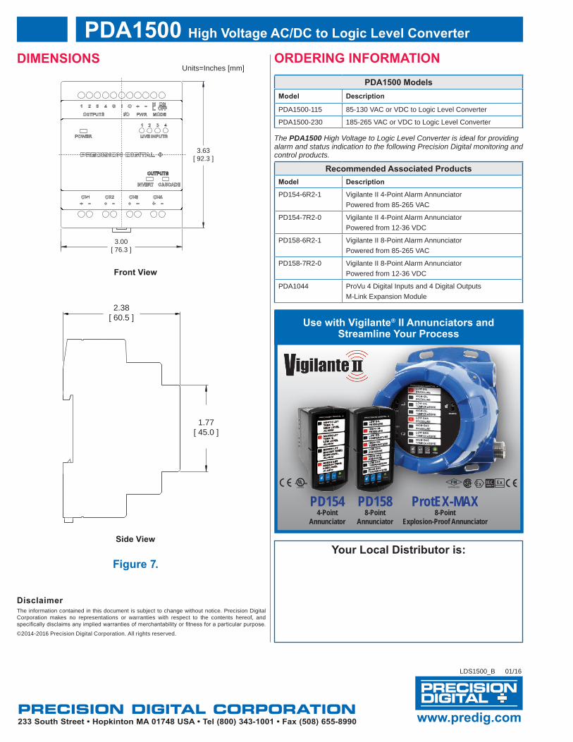
ORDERINGINFORMATIONPDA1500Models
Model Description
PDA1500-115 85-130 VAC or VDC to Logic Level Converter
PDA1500-230 185-265 VAC or VDC to Logic Level Converter
The PDA1500 High Voltage to Logic Level Converter is ideal for providing alarm and status indication to the following Precision Digital monitoring and control products.
RecommendedAssociatedProductsModel Description
PD154-6R2-1 Vigilante II 4-Point Alarm AnnunciatorPowered from 85-265 VAC
PD154-7R2-0 Vigilante II 4-Point Alarm AnnunciatorPowered from 12-36 VDC
PD158-6R2-1 Vigilante II 8-Point Alarm AnnunciatorPowered from 85-265 VAC
PD158-7R2-0 Vigilante II 8-Point Alarm AnnunciatorPowered from 12-36 VDC
PDA1044 ProVu 4 Digital Inputs and 4 Digital OutputsM-Link Expansion Module
DisclaimerThe information contained in this document is subject to change without notice. Precision Digital Corporation makes no representations or warranties with respect to the contents hereof, and specifically disclaims any implied warranties of merchantability or fitness for a particular purpose.
©2014-2016 Precision Digital Corporation. All rights reserved.
YourLocalDistributoris:
DIMENSIONS
3.63[ 92.3 ]
3.00[ 76.3 ]
2.38[ 60.5 ]
1.77[ 45.0 ]
FrontView
SideView
Units=Inches [mm]
PD154 4-Point
Annunciator
PD1588-Point
Annunciator
ProtEX-MAX8-Point
Explosion-Proof Annunciator
UsewithVigilante®IIAnnunciatorsandStreamlineYourProcess
Figure7.


![Redemption presentation11[1] Group 087](https://static.fdocuments.us/doc/165x107/5584a083d8b42a125c8b45e8/redemption-presentation111-group-087.jpg)


![Page 2 Phone 087 2513126 • 087 2330398 Kenmare News News Feb 2013.pdf · Page 2 Phone 087 2513126 • 087 2330398 Kenmare News Dear Editor, ... wedding album; The wedding [book]](https://static.fdocuments.us/doc/165x107/5b78280a7f8b9a515a8e9ea6/page-2-phone-087-2513126-087-2330398-kenmare-news-feb-2013pdf-page-2-phone.jpg)