PCI SDK User s Manual - Brookhaven National Laboratoryjfried/SEB/software/JUNK/unix/pcisdk300... ·...
88
PLX PCI SDK SOFTWARE DEVELOPMENT KIT USER’S MANUAL Version 3.0 Copyright 1999 PLX Technology, Inc. All rights reserved.
Transcript of PCI SDK User s Manual - Brookhaven National Laboratoryjfried/SEB/software/JUNK/unix/pcisdk300... ·...

PLX PCI SDKSOFTWARE DEVELOPMENT KIT
USER’S MANUAL
Version 3.0
Copyright 1999 PLX Technology, Inc. All rights reserved.

NoticeCopyright © 1999, PLX Technology, Inc.. All rights reserved.
This document contains proprietary and confidential information of PLX Technology Inc. (PLX). Thecontents of this document may not be copied nor duplicated in any form, in whole or in part, without priorwritten consent from PLX Technology, INC..
PLX provides the information and data included in this document for your benefit, but it is not possible forus to entirely verify and test all of this information in all circumstances, particularly information relating tonon-PLX manufactured products. PLX makes no warranties or representations relating to the quality,content or adequacy of this information. Every effort has been made to ensure the accuracy of this manual,however, PLX assumes no responsibility for any errors or omissions in this document. PLX shall not beliable for any errors or for incidental or consequential damages in connection with the furnishing,performance, or use of this manual or the examples herein. PLX assumes no responsibility for any damageor loss resulting from the use of this manual; for any loss or claims by third parties which may arisethrough the use of this SDK; and for any damage or loss caused by deletion of data as a result ofmalfunction or repair. The information in this document is subject to change without notice.
Product and Company names are trademarks or registered trademarks of their respective owners.
Document number: PCI-SDK-Man-PI-3.0

PLX SOFTWARE LICENSE AGREEMENTTHIS PLX SOFTWARE DEVELOPMENTKIT INCLUDES PLX SOFTWARE THAT ISLICENSED TO YOU UNDER SPECIFICTERMS AND CONDITIONS. CAREFULLYREAD THE TERMS AND CONDITIONSPRIOR TO USING THIS SOFTWAREDEVELOPMENT KIT. OPENING THISPACKAGE OR INITIAL USE OF THISSOFTWARE DEVELOPMENT KITINDICATES YOUR ACCEPTANCE OF THETERMS AND CONDITIONS. IF YOU DONOT AGREE WITH THEM, YOU SHOULDRETURN THE ENTIRE SOFTWAREDEVELOPMENT KIT TO PLX.
LICENSE Copyright (c) 1999 PLXTechnology, Inc.
This PLX Software License agreement is a legalagreement between you and PLX Technology, Inc. forthe PLX Software Development Kit (SDK), alsoreferred to as “PLX SDK” which is provided on theenclosed PLX CD-ROM, or may be recorded on othermedia included in this PLX SDK. PLX Technologyowns this PLX SDK. The PLX SDK is protected bycopyright laws and international copyright treaties, aswell as other intellectual property laws and treaties,and is licensed, not sold. If you are a rightful possessorof the PLX SDK, PLX grants you a license to use thePLX SDK as part of or in conjunction with a PLXchip on a per project basis. PLX grants thispermission provided that the above copyright noticeappears in all copies and derivatives of the PLX SDK.Use of any supplied runtime object modules orderivatives from the included source code in anyproduct without a PLX Technology, Inc. chip isstrictly prohibited. You obtain no rights other thanthose granted to you under this license. You maycopy the PLX SDK for backup or archival purposes.You are not authorized to use, merge, copy, display,adapt, modify, execute, distribute or transfer, reverseassemble, reverse compile, decode, or translate thePLX SDK except to the extent permitted by law.
GENERALIf you do not agree to the terms and conditions of thisPLX Software License Agreement, do not install or
PLX SDK License Agreement
use the PLX SDK and promptly return the entireunused PLX SDK to PLX Technology, Inc. You mayterminate your license at any time. PLX Technologymay terminate your license if you fail to comply withthe terms and conditions of this License Agreement. Ineither event, you must destroy all your copies of thisPLX SDK. Any attempt to sub-license, rent, lease,assign or to transfer the PLX SDK except as expresslyprovided by this license, is hereby rendered null andvoid.
WARRANTYPLX Technology, Inc. provides this PLX SDKAS IS, WITHOUT ANY WARRANTY,EXPRESS OR IMPLIED, INCLUDINGWITHOUT LIMITATION, ANY WARRANTYOF MERCHANTIBILITY OR FITNESS FOR APARTICULAR PURPOSE. PLX makes noguarantee or representations regarding the use of, orthe results based on the use of the software anddocumentation in terms of correctness, or otherwise;and that you rely on the software, documentation, andresults solely at your own risk. In no event shall PLXbe liable for any loss of use, loss of business, loss ofprofits, incidental, special or, consequential damagesof any kind. In no event shall PLX’s total liabilityexceed the sum paid to PLX for the product licensedhere under.
PLX Copyright Message Guidelines
The following copyright message along with thefollowing text must appear in all software productsgenerated and distributed which use the PLX APIlibraries:
“Copyright (c) 1999 PLXTechnology, Inc.”Requirements:• Arial font• Font size 12 (minimum)• Bold type• Must appear as shown above in the first section
or the so called “Introduction Section” of allmanuals
• Must also appear as shown above in thebeginning of source code as a comment

This page is intentionally left blank.

PCI SDK User’s Manual ©PLX Technology, Inc., 1999 i
Table of Contents
1. INTRODUCTION.........................................................................................1-1
1.1 GENERAL INFORMATION .................................................................................................. 1-11.2 ABOUT THIS MANUAL ...................................................................................................... 1-11.3 PCI SDK FEATURES......................................................................................................... 1-11.4 WHERE TO GO FROM HERE ............................................................................................. 1-11.5 OTHER PCI SDK MANUALS ............................................................................................. 1-21.6 CONVENTIONS.................................................................................................................. 1-2
1.6.1 Windows Programming Conventions ....................................................................................1-21.7 TERMINOLOGY ................................................................................................................. 1-21.8 DEVELOPMENT TOOLS ..................................................................................................... 1-3
1.8.1 IOP 480 Third Party Development Tools ..............................................................................1-31.9 CUSTOMER SUPPORT........................................................................................................ 1-3
2. GETTING STARTED ..................................................................................2-1
2.1 PCI SDK INSTALLATION .................................................................................................. 2-12.1.1 Unpacking..............................................................................................................................2-12.1.2 Minimum System Requirements............................................................................................2-12.1.3 Development Requirements...................................................................................................2-12.1.4 Software Installation ..............................................................................................................2-2
2.1.4.1 Windows NT Installation Procedures .......................................................................................... 2-22.1.4.2 Windows 98 Installation Procedures ........................................................................................... 2-22.1.4.3 Uninstalling All Previous Versions Of The PCI SDK Software.................................................. 2-42.1.4.4 PCI SDK V3.0 Compatibility ...................................................................................................... 2-42.1.4.5 Troubleshooting........................................................................................................................... 2-5
2.2 UNDERSTANDING THE PCI SDK...................................................................................... 2-62.2.1 IOP Software..........................................................................................................................2-6
2.2.1.1 Introduction ................................................................................................................................. 2-62.2.1.2 IOP Applications ......................................................................................................................... 2-62.2.1.3 How to Compile the Samples ...................................................................................................... 2-7
2.2.2 Windows Based Host Software............................................................................................2-102.2.2.1 Introduction ............................................................................................................................... 2-102.2.2.2 Windows NT Device Drivers .................................................................................................... 2-112.2.2.3 Windows 98 Device Drivers...................................................................................................... 2-15
2.3 USING THE PCI SDK WITH A NEW BOARD .................................................................. 2-162.4 USING THE IOP API LIBRARIES WITH OTHER COMPILERS........................................... 2-17
3. PCI SDK SOFTWARE ARCHITECTURE OVERVIEW...............................3-1
3.1 ASSUMPTIONS................................................................................................................... 3-13.1.1 PCI SDK Assumptions ..........................................................................................................3-13.1.2 IOP API And IOP Software Assumptions .............................................................................3-13.1.3 PCI API And Win32 Software Assumptions .........................................................................3-1
3.2 OVERVIEW ........................................................................................................................ 3-23.3 SOFTWARE ARCHITECTURE.............................................................................................. 3-33.4 IOP SOFTWARE ARCHITECTURE...................................................................................... 3-3
3.4.1 Board Support Package (BSP) ............................................................................................... 3-43.4.1.1 Microprocessor Initialization Module.......................................................................................... 3-53.4.1.2 Board Initialization Module......................................................................................................... 3-53.4.1.3 The Main() And AppMain() Functions........................................................................................ 3-6
3.4.2 IOP API Library.....................................................................................................................3-83.4.2.1 DMA Resource Manager............................................................................................................. 3-8
3.4.3 Back-End Monitor ...............................................................................................................3-123.4.3.1 BEM Command Format and Commands................................................................................... 3-13

ii ©PLX Technology, Inc., 1999 PCI SDK User’s Manual
3.4.3.2 BEM Reply Format ....................................................................................................................3-143.4.3.3 BEM Command Protocols..........................................................................................................3-14
3.4.4 Methods For Debugging IOP Applications..........................................................................3-203.4.4.1 Operation Of The Back-End Monitor In A System ....................................................................3-20
3.4.5 IOP Applications..................................................................................................................3-213.4.5.1 IOP Memory And IOP Applications ..........................................................................................3-213.4.5.2 MiniBSP Application .................................................................................................................3-22
3.4.6 Porting The PCI SDK To New Platforms ............................................................................3-223.4.7 Support For Multiple PLX chips On One Board..................................................................3-23
3.5 HOST WIN32 SOFTWARE ARCHITECTURE...................................................................... 3-233.5.1 GUI Application PLXMon 99..............................................................................................3-24
3.5.1.1 Serial Communication................................................................................................................3-243.5.1.2 PCI API/Device Driver Communication ....................................................................................3-25
3.5.2 Win32 Applications And The PCI SDK ..............................................................................3-253.5.3 Win32 Device Driver Overview...........................................................................................3-25
3.5.3.1 PLX Chip Device Driver Module...............................................................................................3-263.5.3.2 PLX Chip Services Module........................................................................................................3-26
3.5.4 Creating A New Driver ........................................................................................................3-263.5.5 Device Driver Features.........................................................................................................3-273.5.6 Distribution of PLX Device Drivers and PLXApi.Dll File ..................................................3-27
3.5.6.1 Installation of PlxApi.dll File .....................................................................................................3-273.5.6.2 Installation of PLX Device Driver..............................................................................................3-27
4. REAL TIME OPERATING SYSTEM SUPPORT ........................................4-1
4.1 GENERAL INFORMATION .................................................................................................. 4-14.2 GETTING STARTED ........................................................................................................... 4-14.3 MINIMUM REQUIREMENTS............................................................................................... 4-14.4 INSTALLATION .................................................................................................................. 4-14.5 WHAT’S INCLUDED?......................................................................................................... 4-24.6 WHICH VXWORKS ROM IMAGE SHOULD I USE?............................................................ 4-34.7 PLX VXWORKS BSP/PLX API DEMONSTRATION ......................................................... 4-3
4.7.1 Updating the PCI 9054RDK-860 or CompactPCI 9054RDK-860 onboard FLASH .............4-34.7.2 PLX API functions Demonstration ........................................................................................4-3
4.7.2.1 Stand alone VxWorks Target Shell Demo (No Tornado and no Target Server present) ..............4-34.7.2.2 Tornado VxWorks Host Shell Demo............................................................................................4-4
4.8 HOW TO REBUILD THE BSP AND APPLICATION IMAGES? .............................................. 4-104.8.1 Setup the makefile to build PLX VxWorks Boot ROM.......................................................4-104.8.2 Setup the custom project to build PLX demo application ....................................................4-10
4.9 TORNADO 1.0.1 AND TORNADO 2.0 COMPATIBILITY ..................................................... 4-11
5. RDK SOFTWARE QUICK REFERENCE ...................................................5-1
5.1 IOP 480RDK.................................................................................................................... 5-15.2 PCI 9054RDK-860........................................................................................................... 5-25.3 COMPACTPCI 9054RDK-860........................................................................................... 5-35.4 PCI 9080RDK-401B ........................................................................................................ 5-55.5 PCI 9080RDK-860........................................................................................................... 5-65.6 PCI 9080RDK-SH3.......................................................................................................... 5-85.7 PCI 9080RDK-RC32364................................................................................................ 5-10
APPENDIX A. INDEX.......................................................................................... I

PCI SDK User’s Manual ©PLX Technology, Inc., 1999 iii
List of FiguresFIGURE 2-1 COMPONENTS OF THE PCI SDK................................................................................ 2-1FIGURE 2-2 WINDOWS HOST SOFTWARE LAYOUT FOR PCI SDK V3.0..................................... 2-10FIGURE 2-3 THE DEVICES UTILITY WINDOW............................................................................. 2-11FIGURE 2-4 THE EVENT VIEW WINDOW. ................................................................................... 2-12FIGURE 2-5 THE DETAILED EVENT WINDOW............................................................................. 2-12FIGURE 2-6 REGISTRY INFORMATION FOR PCI 9080 DEVICE DRIVER ON WINDOWS NT ........ 2-13FIGURE 2-7 REGISTRY INFORMATION FOR PCI 9054 DEVICE DRIVER ON WINDOWS NT......... 2-13FIGURE 2-8 REGISTRY INFORMATION FOR IOP 480 DEVICE DRIVER ON WINDOWS NT .......... 2-13FIGURE 2-9 THE PCI SDK DEVICE DRIVER WIZARD ................................................................ 2-15FIGURE 3-1 THE PCI SDK SOFTWARE ARCHITECTURE............................................................... 3-2FIGURE 3-2 THE IOP SOFTWARE ARCHITECTURE....................................................................... 3-4FIGURE 3-3 THE DATA STREAM FLOW DIAGRAM . ...................................................................... 3-7FIGURE 3-4 SCATTER-GATHER DMA FLOW DIAGRAM ............................................................... 3-9FIGURE 3-5 BLOCK DMA TRANSFER FLOW DIAGRAM ............................................................. 3-10FIGURE 3-6 THE SHUTTLE DMA FLOW DIAGRAM .................................................................... 3-11FIGURE 3-7 DIAGRAM OF THE IOP MEMORY USAGE ................................................................ 3-22FIGURE 3-8 THE HOST SOFTWARE ARCHITECTURE................................................................... 3-24FIGURE 3-9 THE PLX DEVICE DRIVER LAYOUT ........................................................................ 3-26FIGURE 4-1 STAND ALONE VXWORKS TARGET SHELL DEMO SCREEN...................................... 4-4FIGURE 4-2 REBOOT THE STAND ALONE VXWORKS TARGET SHELL DEMO .............................. 4-5FIGURE 4-3 BACK END PROPERTY PAGE...................................................................................... 4-6FIGURE 4-4 CORE FILE AND SYMBOLS PROPERTY PAGE ............................................................. 4-6FIGURE 4-5 VIRTUAL CONSOLE PROPERTY PAGE........................................................................ 4-7FIGURE 4-6 TGTSVR - CONSOLE................................................................................................... 4-7FIGURE 4-7 TORNADO SHELL PROMPT ........................................................................................ 4-8FIGURE 4-8 TGTSVR - CONSOLE NO. 1......................................................................................... 4-9FIGURE 4-9 TGTSVR - CONSOLE NO. 2......................................................................................... 4-9FIGURE 4-10 CUSTOMIZE BUILDS SCREEN NO. 1 ...................................................................... 4-10FIGURE 4-11 CUSTOMIZE BUILDS SCREEN NO. 2 ...................................................................... 4-11FIGURE 4-12 OPTIONS................................................................................................................ 4-11FIGURE 4-13 BUILD VXWORKS.................................................................................................. 4-12FIGURE 4-14 CONFIGURE TARGET SERVERS.............................................................................. 4-13FIGURE 5-1 CONFIGURATION EEPROM SETTINGS FOR THE IOP 480RDK ................................ 5-2FIGURE 5-2. CONFIGURATION EEPROM SETTINGS FOR THE PCI 9054RDK-860 ...................... 5-3FIGURE 5-3. CONFIGURATION EEPROM SETTINGS FOR THE COMPATCTPCI 9054RDK-860 .... 5-5FIGURE 5-4. CONFIGURATION EEPROM SETTINGS FOR THE PCI 9080RDK-401B.................... 5-6FIGURE 5-5. CONFIGURATION EEPROM SETTINGS FOR THE PCI 9080RDK-860 ...................... 5-8FIGURE 5-6. CONFIGURATION EEPROM SETTINGS FOR THE PCI 9080RDK-SH3 ................... 5-10

iv ©PLX Technology, Inc., 1999 PCI SDK User’s Manual
List of TablesTABLE 3-1. BEM COMMANDS ................................................................................................... 3-13TABLE 5-1. BASIC INFORMATION ABOUT IOP 480RDK.............................................................. 5-1TABLE 5-2. BASIC INFORMATION ABOUT PCI 9054RDK-860..................................................... 5-2TABLE 5-3. BASIC INFORMATION ABOUT COMPACTPCI 9054RDK-860 .................................... 5-4TABLE 5-4. BASIC INFORMATION ABOUT PCI 9080RDK-401B.................................................. 5-5TABLE 5-5. BASIC INFORMATION ABOUT PCI 9080RDK-860..................................................... 5-7TABLE 5-6. BASIC INFORMATION ABOUT PCI 9080RDK-SH3 ................................................... 5-8TABLE 5-7. BASIC INFORMATION ABOUT PCI 9080RDK-RC32364 ......................................... 5-10

PCI SDK User’s Manual ©PLX Technology, Inc., 1999 1-1
1. Introduction
1.1 General InformationPLX Technology offers PCI bus interface chips that address a range of adapter and embeddedsystem applications. Our PCI chips work well with a variety of CPUs and embedded controllers,including the IBM PowerPC 40x family, Motorola MPC860/850 and 68360, as well as thePowerPC 60x family, Analog Devices Sharc, various Texas Instruments DSPs, the Intel i960family, Hitachi SuperH family, IDT MIPS, and others. If the design does not require amicroprocessor, our chips are easily configured to run without the aid of a CPU. PLX providesSoftware Development Kits (SDK), Reference Design Kits (RDK) and Hardware Design Kits(HDK) that facilitate your PCI design development.
1.2 About This ManualThe PLX family of 32-bit I/O processor and I/O accelerator chips connects the PCI bus to Intel,Power PC and other processors. They provide full Intelligent I/O (I2O) compatibility. The PCISoftware Development Kit (PCI SDK) provides a powerful I/O Platform ApplicationProgramming Interface (IOP API), and Windows software that are used to control PLX devices.We are confident that through the use of the PCI SDK, your PLX designs will be brought tomarket faster and more efficiently.
This manual provides information about the functionality of the PCI SDK. Customers have thechoice of using the PCI SDK with any PLX Reference Design Kit (RDK), or a generic device thatuses a PLX chip. Users should consult this manual when installing the PCI SDK and for generalinformation.
1.3 PCI SDK FeaturesThe PCI SDK includes the following features:
• A feature based IOP API, with support for a variety of PLX PCI chips;
• Board Support Package (BSP) that allows customization of the PCI SDK;
• A Back-End Monitor application used for basic debugging;
• IOP DMA Resource Manager that supports three modes of operation;
• A PCI API and device drivers compatible with Windows NT/98; and,
• PLXMon 99, a Windows Graphical User Interface (GUI) application used to configure,modify PLX PCI devices, and download IOP applications to the local RAM.
1.4 Where To Go From HereThe following is a brief summary of the chapters to help guide your reading of this manual:
Chapter 2, Getting Started, discusses how to start using the PCI SDK and some of theapplications provided.

1-2 ©PLX Technology, Inc., 1999 PCI SDK User’s Manual
Chapter 3, PCI SDK Software Architecture Overview, describes the layout of the PCI SDKsoftware.
1.5 Other PCI SDK ManualsThe PCI SDK includes the following manuals which users should consult for design details:
• PCI SDK Programmer’s Reference Manual: This manual covers all software design issuesregarding the device drivers, API and user applications.
• PLXMon 99 User’s Manual: This manual describes the usage of the PLXMon 99 application.
• IOP 480 CPU API Programmer’s Reference Manual: This manual covers the IOP 480 CPUAPI and will be created only as a PDF file in Acrobat format during the PCI SDKinstallation.
• PLX Device Driver Manual: This manual covers the PLX device drivers and servicemodules, which are the core parts of the PLX device drivers. The manual will be created onlya PDF file in Acrobat format during the PCI SDK installation.
• PLX RDK Manufacturing Test Specification: This manual covers the basic information aboutthe PLX RDK Manufacturing Test program and will be created only as a PDF file in Acrobatformat during the PCI SDK installation.
1.6 ConventionsPlease note that when software samples are provided the following notations are used:
• italics are used to represent variables, function names, and program names;
• courier is used to represent source code given as examples.
1.6.1 Windows Programming ConventionsSome designers may not be familiar with Windows programming conventions. Therefore, a fewconventions have been noted below, for example:
• PU32 data is analogous to U32 *data or unsigned long *data; and
• IN and OUT are used to distinguish between parameters that are being passed into APIfunctions and parameters that are being returned by API functions.
1.7 TerminologyAll references to Windows NT assume Windows NT 4.0 or higher and may be denoted asWinNT.
All references to Windows 98 may be denoted as Win98.
Win32 references are used throughout this manual to mean any application that is compatiblewith the Windows 32-bit environment.
All references to IOP (I/O Platform) throughout this manual denote the RDK board and allreferences to IOP software denote the software running on the RDK board.

PCI SDK User’s Manual ©PLX Technology, Inc., 1999 1-3
All references to FLASH should be replaced with EPROM for users of the PCI 9080RDK-SH3and PCI 9080RDK-RC32364 Reference Design Kits.
1.8 Development ToolsDevelopment tools used to develop the PCI SDK include:
• Win32 Applications: Microsoft Visual C++ 5.0, with Microsoft Developer Studio;
• Win32 Applications: Microsoft Platform Software Development Kit (SDK);
• Windows NT 4.0 Drivers: Microsoft Windows NT 4.0 Device Driver Kit (DDK);
• Windows 98 Drivers: Microsoft Windows 98 Device Driver Kit (DDK);
• IOP 480RDK IOP Software:
1. IBM High C/C++ PowerPC Cross-Compiler, version 1.0 (7/31/96); and IBM 401 EVBSoftware Support Package, version 1.6.4 (4/1/97)
2. DIAB Data, Inc. Compiler and Linker for PowerPC, version 4.0b and version 4.3p6;
• PCI 9080RDK-860, CompactPCI and PCI 9054RDK-860 IOP Software: DIAB Data, Inc.Compiler and Linker for the PowerPC, version 4.0b and version 4.3p6;
• PCI 9080RDK-401B Software:
1. IBM High C/C++ PowerPC Cross-Compiler, version 1.0 (7/31/96); and IBM 401 EVBSoftware Support Package, version 1.6.4 (4/1/97)
2. DIAB Data, Inc. Compiler and Linker for PowerPC, version 4.0b and version 4.3p6;
• PCI 9080RDK-RC32364 IOP Software: IDT/c Cross Compiler System Version 5.5/7.0 GNUDeveloper’s Kit.
• PCI 9080RDK-SH3 IOP Software: Cygnus GNU compiler: gcc version 2.7-96q3a
1.8.1 IOP 480 Third Party Development ToolsIn addition to the IBM High C/C++ PowerPC Cross-Compiler and the Diab Data PowerPCCompiler and Linker, other PowerPC compilers may be used to develop IOP 480 basedapplications. The PLX PCI SDK version 3.0 complies to the ANSI C code standard. Minimalchanges to batch and make files may be required if using compilers other than the IBM and DiabData PowerPC compilers.
PLX Partners and recommended PowerPC compilers:
• MetaWare High C/C++ for PowerPC
• Green Hills Software PowerPC C/C++ Optimizing Compilers
• Mentor Graphics Microtec C & C++ Compilers for PowerPC
• Metrowerks CodeWarrior for PowerPC
1.9 Customer SupportPrior to contacting PLX customer support, please ensure that you are situated close to thecomputer that has the PCI SDK installed and have the following information:

1-4 ©PLX Technology, Inc., 1999 PCI SDK User’s Manual
1. Model number of the PLX PCI RDK (if any);
2. PLX PCI SDK version (if any);
3. Host Operating System and version;
4. Description of your intended design:
• PLX chip used
• Microprocessor
• Local Operating System and version (if any)
• I/O
5. Description of your problem; and
6. Steps to recreate the problem.
You may contact PLX customer support at:
Address: PLX Technology, Inc. Attn. Technical Support
390 Potrero AvenueSunnyvale, CA 94086
Phone: 408-774-9060Fax: 408-774-2169Web: http://www.plxtech.com
You may send email to one of the following addresses:

PCI SDK User’s Manual ©PLX Technology, Inc., 1999 2-1
2. Getting Started
2.1 PCI SDK Installation
2.1.1 UnpackingThe PCI SDK comes complete with thefollowing items (see Figure 2-1)
• PCI SDK User’s Manual (this document);
• PCI SDK Programmer’s ReferenceManual;
• PLXMon 99 User's Manual; and
• PCI SDK CD-ROM.
Please take the time now to verify that yourPCI SDK is complete. If not, please contactCustomer Support.
2.1.2 Minimum SystemRequirementsMinimum host system requirements for the PCI SDK are as follows:
• Windows NT 4.0 with Service Pack 3, or Windows 98;
• 32MB RAM (when used with only one PLX PCI RDK. Additional memory may be requiredif more than one PLX PCI RDK are in the system);
• 80MB hard drive space; and,
• 1 RS 232 serial port.
2.1.3 Development RequirementsThe PCI SDK development environment is either the Window NT 4.0 or Windows 98 operatingsystems.
The PCI API was developed using Microsoft Developer Studio, supplied with Microsoft VisualC++ 5.0 and the Microsoft Platform Software Development Kit.
The WinNT device drivers were developed using the Microsoft Windows NT DDK, version 4.0and Microsoft Visual C++ 5.0.
The Win32 Driver Model (WDM) device drivers were developed using the Microsoft Windows98 DDK and Microsoft Visual C++ 5.0.
PCI SDK
Programmer’s
Reference
Manual
PLXMon 99
User’sManual
PCI SDK
InstallationCD-ROM
PCI SDK
User’sManual
Figure 2-1 Components of the PCI SDK

2-2 ©PLX Technology, Inc., 1999 PCI SDK User’s Manual
2.1.4 Software Installation
2.1.4.1 Windows NT Installation Procedures
To install the PCI SDK Support Software, complete the following:
Note: All previous PCI SDK versions located on the computer must be removed before installinga PCI SDK update. Refer to section 2.1.4.3 for more details.
1. Insert the CD-ROM into the appropriate CD-ROM drive.
2. Run “D:\Install.exe” either by typing it at a command prompt or by choosing the Run optionof the Start Menu (where “D:” is the drive letter for the CD-ROM Drive).
3. This will launch the Install Wizard application that will ask you to select the PLX RDK thatyou are using. The appropriate PCI SDK version will then be installed.
4. Reboot the computer after the installation. This completes the PCI SDK software installation.
Note: For proper WinNT installation, the PCI SDK should be installed by a user with“administrator” user rights.
The default installation directory may be changed from default path (C:\Plx\PciSdk300) to anydrive and path that is desired. This document uses “<INSTALLPATH>” to denote the installationdirectory.
2.1.4.1.1 Windows NT Device Driver Installation
The Windows NT installation wizard takes care of the device driver installation.
2.1.4.2 Windows 98 Installation Procedures
The installation of the PCI SDK software onto a Win98 system requires two steps: Install the PCISDK files and start the Win98 device driver(s). The following two sections describe how tocompletely install the PCI SDK Support Software for Win98.
2.1.4.2.1 Windows 98 Software Installation
To install the PCI SDK software, complete the following:
Note: All previous PCI SDK versions located on the computer must be removed before installinga PCI SDK update. Refer to section 2.1.4.3 for more details.
1. Ensure no PLX RDK boards are installed in your computer.
2. Insert the CD-ROM into the appropriate CD-ROM drive.
3. Run “D:\Install.exe” either by typing it at a command prompt or by choosing the Run optionof the Start Menu (where “D:” is the drive letter for the CD-ROM Drive). The interactiveinstallation program will install all files.
4. This will launch the Install Wizard application that will ask you to select the PLX RDK thatyou are using. The appropriate PCI SDK version will then be installed.
The default installation directory may be changed from default path (C:\Plx\PciSdk300) toany drive and path that is desired. This document uses “<INSTALLPATH>” to denote theinstallation directory.

PCI SDK User’s Manual ©PLX Technology, Inc., 1999 2-3
This completes the PCI SDK software installation. Proceed to the next section to install theWin98 device driver.
2.1.4.2.2 Windows 98 Device Driver Installation
A device driver is necessary for the PCI SDK software to communicate to the PLX RDK board.PCI SDK applications cannot communicate with any RDK board through the PCI interfacewithout a PCI SDK device driver installed. The installation software used to install the PCI SDKcan not automatically start the device drivers for PLX devices. To start the device driver inWin98, complete the following:
1. After installing the PCI SDK successfully (see the previous section), shutdown the computer.
2. Insert a PLX RDK board into a free PCI slot.
3. Reboot the computer. Windows 98 should first detect the new hardware device with a “NewHardware Found” message box. Acknowledge this message box.
4. Windows 98 displays the “Add New Hardware” Wizard. Windows 98 displays the followingmessage: “This wizard searches for new drivers for:” with the corresponding board namefollowing it. If you are using a PLX RDK board proceed to step 5. If you are using a customReference Design Board with a PLX device then proceed to step 10.
Driver Installation for PLX Reference Design Boards:
5. Click on the “Next” button. Once Windows 98 has completed its search the following promptis displayed: “What do you want Windows to do?” At the prompt select “Search for the bestdriver for your device”. This is the default option. Click on “Next” to continue.
6. The installation wizard asks: “Windows will search […] in any of the following selectedlocations.” Check none of the items in the list and click on “Next” to continue.
7. The device driver is ready to be installed when the installation wizard displays the followingmessage: “Windows is now ready to install the best driver for this device.” Click on “Next”to continue.
8. The device driver installation is complete when Windows 98 displays the following message:“Windows has finished installing the software that your new hardware device requires”.
9. Click on “Finish” to complete the Win98 device driver installation.
Driver Installation for Custom Reference Design Boards with PLX devices:
In order for the custom reference design boards to be treated as one of “Custom (OEM)” boardsduring the following steps, the device and vendor IDs must be:
• Vendor ID = 0x10B5, Device ID = 0x9080 for a PCI 9080 device;
• Vendor ID = 0x10B5, Device ID = 0x9054 for a PCI 9054 device; and
• Vendor ID = 0x10B5, Device ID = 0xF480 for an IOP 480 device.
10. The installation wizard will detect your custom device as a “PCI Bridge”. Click on the“Next” button and then choose the option “Display a list of all the drivers in a specificlocation.” Click “Next”.
11. Select “Other Devices”. Click “Next”.
2-4 ©PLX Technology, Inc., 1999 PCI SDK User’s Manual
12. Now select the column that says “PLX Technology, Inc.” and choose “Custom (OEM) PCI9054 board” if using a PCI 9054 device. Otherwise choose “Custom (OEM) PCI 9080board” if using a PCI 9080 device or "Custom (OEM) IOP 480 board" if using an IOP 480device. The install wizard will warn you that this device driver is not specific for your device.Ignore this warning by choosing “Yes”. Click “Next”.
13. Click “Finish” to complete the Win98 device driver installation.
Note: If you change the PLX RDK board from one slot to another, Windows 98 will treat it as a“New Hardware” and will display the same dialog.
Once the Win98 device driver installation is complete it is ready to run without having to rebootthe system.
2.1.4.3 Uninstalling All Previous Versions Of The PCI SDK Software
Prior to installing a new version of the PCI SDK, you should first uninstall all older versions.There is interaction between PCI and IOP software modules and it is important not to mixreleases. To remove all PCI SDK Software, including device drivers, complete the following:
1. Stop all PLX applications;
2. Open the Windows Control Panel;
3. Double click on the Add/Remove Programs icon in the Control Panel window;
4. Choose the PCI SDK package from the item list; and
5. Click the Add/Remove... button.
Note: This only removes the files that were originally installed by the PCI SDK installationprogram. For proper removal in WinNT, the PCI SDK should be removed by a user with“administrator” user rights.
This completes the PCI SDK software removal.
2.1.4.4 PCI SDK V3.0 Compatibility
Due to interaction between host and IOP software components it is very important that PCI SDKreleases are the same on both sides (i.e. if the host software is from PCI SDK V3.0, then the IOPsoftware should also be from PCI SDK V3.0 as well). If you have recently purchased a PLXRDK then it will already contain the correct IOP software preprogrammed, so you need notconcern yourself with this section. However, if you have purchased the PCI SDK as an upgradeand intend to use it with an earlier PLX RDK board you will need to upgrade the RDK board’sFLASH with a current version. This is necessary to ensure that nothing unpredictable occurs dueto incompatibilities with modules.
Although it is important to have your host and IOP software from the same release, the IOP APIand PCI API are almost compatible with PCI SDK v2.0 and higher. PLX has developed an APImodel that is portable and will continue to support this model in future releases. The previousparagraph is necessary because some PLXMon 99 features rely on a communication protocolwith the IOP BSP and the protocol has improved in each release. The IOP API and PCI API arefully compatible between releases.
Users who are upgrading their PCI SDK and intend to use it with an earlier PLX RDK boardshould follow the steps below.

PCI SDK User’s Manual ©PLX Technology, Inc., 1999 2-5
To upgrade your FLASH image, follow the steps below:• Users of the IOP480RDK may use PLXMon 99, as described in the PLXMon 99 User
Manual, to download the FLASH image file “<INSTALLPATH>\hw\Flash\Iop480rdk.bin” tothe IOP480RDK. The image should be usually programmed at FLASH offset 0x60000.
• Users of the PCI 9054RDK-860 may use PLXMon 99 to download the FLASH image“<INSTALLPATH>\hw\Flash\9054RDK-860.bin” to the PCI 9054RDK-860. The imageshould be programmed at FLASH offset 0x00000.
• Users of the CompactPCI 9054RDK-860 may use PLXMon 99 to download the FLASHimage “<INSTALLPATH>\hw\Flash\CPCI9054RDK-860.bin” to the CompactPCI 9054RDK-860. The image should be programmed at FLASH offset 0x00000.
• Users of the PCI 9080RDK-401B may use PLXMon 99 to download the FLASH image“<INSTALLPATH>\hw\Flash\9080RDK-401B.bin” to the PCI 9080RDK-401B. The imageshould be usually programmed at FLASH offset 0x60000.
• Users of the PCI 9080RDK-860 must use a device programmer to reprogram the FLASHwith FLASH image “<INSTALLPATH>\hw\Flash\9080RDK-860.bin”. The image should beprogrammed at FLASH offset 0x00000.
• Users of the PCI 9080RDK-SH3 must use a device programmer to reprogram the EPROMwith the FLASH image “<INSTALLPATH>\hw\Flash\9080RDK-Sh3.bin”. The image shouldbe programmed at EPROM offset 0x00000.
• Users of the PCI 9080RDK-RC32364 must use a device programmer to reprogram theEPROM with the image file “<INSTALLPATH>\hw\Flash\9080RDK-RC32364.bin”. Theimage should be programmed at EPROM offset 0x00000.
2.1.4.5 Troubleshooting
You may experience difficulties using the PCI SDK with Windows NT with low memory andmultiple PLX RDK boards. If you notice that one of your RDK boards is not being assigned theproper memory resources by the PCI BIOS (e.g. no address provided to the Local Space 0address) it is most likely due to a common memory problem with WinNT. It is recommended thatusers increase the amount of available system pages in their System Registry by following thesteps below;
1. From a command prompt type: regedt32. This will bring up the Registry Editor window.(This editor looks similar to the Windows Explorer application.)
2. Select the HKEY_LOCAL_MACHINE on Local Machine window from within the RegistryEditor.
3. Open the SYSTEM folder.
4. From the SYSTEM folder, open the CurrentControlSet folder.
5. From the CurrentControlSet folder, open the Control folder.
6. From the Control folder, open the Session Manager folder.
7. From the Session Manager folder, open the Memory Management folder.
8. From the Memory Management folder, change the value of the SystemPages key from0x0 to 0x13880.
If problems persist, please contact Customer Support.

2-6 ©PLX Technology, Inc., 1999 PCI SDK User’s Manual
2.1.4.5.1 Driver Interrupt Sharing
The PCI SDK device drivers have interrupt sharing enabled. This allows PLX devices to sharethe same interrupt line as other devices. However, in order to share interrupts with non-PLXdevices the device driver for the non-PLX device must also support sharing. Because manydevice drivers do not support interrupt sharing, the PCI SDK can only be guaranteed to functionproperly with other PLX devices.
In PCI systems, the BIOS often assigns the same interrupt to multiple devices; however, therespective device drivers must support these "shared interrupts". A driver that does not supportthis feature may prevent the PLX driver from functioning correctly. A possible workaround forthis condition is to manually configure the BIOS to assign a free interrupt to the PLX device.
2.2 Understanding The PCI SDK
2.2.1 IOP Software
2.2.1.1 Introduction
The PCI SDK includes several samples of IOP applications. Their purpose is to demonstrate howdesigners can interact with the PLX chip from IOP software. The IOP applications are user-interactive and require PLXMon 99 with a serial cable link.
The IOP applications are designed specifically to run on a PLX RDK board. However, the IOPapplications can be used as a good starting point when designing custom target platforms.
2.2.1.2 IOP Applications
The PCI SDK contains several sample applications. By default, all PLX RDK boards contain the“monitor” application preprogrammed in FLASH memory. This application is a command lineinterpreter, which accepts commands from the serial port and acts accordingly. The monitorprogram enables you to read from or write to memory in 32-bit, 16-bit and 8-bit units. Completesource code for this application is provided in the PCI SDK. Please refer to the PLXMon 99User’s Manual for more information on how to communicate to the PLX RDK boards IOPapplications.
In the <INSTALLPATH>\hw\FLASH directory, there are default ROM images for all the RDKssupported by the PCI SDK. Every RDK FLASH is programmed and shipped with a relevantimage from this directory. The user can choose to restore the FLASH to the default ROM imageusing the corresponding FLASH image from this directory later if the FLASH image on theuser’s RDK board is corrupted for whatever reason.
2.2.1.2.1 MiniBSP Application
MiniBSP is included in the PCI SDK to provide a good starting point for users who have anuntested hardware device and for this reason, it is limited in features and functionality. It providesbare minimum boot-up code for most boards. This application configures the microprocessor, thePLX chip, and proceeds to blink the LED, if any, that is connected to one of the PLX chip’sUSER pins. To use the MiniBSP application, you should program the binary image into theFLASH using a FLASH chip programmer. Once the FLASH is programmed, put the FLASH intothe board, and reboot the board. If the LED blinks, then the MiniBSP application configured the

PCI SDK User’s Manual ©PLX Technology, Inc., 1999 2-7
board properly. Otherwise, you have to modify the MiniBSP source file for your hardwareconfiguration.
Note:
1. This ROM application is provided as a bare bones ROM application useful for confirming thefunctionality of new boards. It does not contain any PCI SDK features that are described inany PCI SDK manual.
2. "MiniBSP" and "MiniROM" refer to essentially the same application. (Users of previousversion of SDK may be familiar with the term "MiniROM").
2.2.1.3 How to Compile the Samples
There are four compiler packages used in the PCI SDK to compile code for all the seven RDKssupported by the PCI SDK. The four compiler packages are as follows:
1. IBM High C/C++ PowerPC Cross-Compiler, version 1.0 (7/31/96); and IBM 401 EVBSoftware Support Package, version 1.6.4 (4/1/97). This compiler set supports the followingtwo RDKs:
• PCI 9080RDK-401B; and
• IOP 480RDK.
2. DIAB Data, Inc. Compiler and Linker for the PowerPC, version 4.0b or version 4.3p6. Thiscompiler package supports the following five RDKs:
• PCI 9080RDK-860;
• PCI 9054RDK-860;
• CompactPCI 9054RDK-860;
• PCI 9080RDK-401B; and
• IOP 480RDK.
3. IDT/c Cross Compiler System Version 5.5/7.0 GNU Developer’s Kit. This compiler packagesupports the PCI 9080RDK-RC32364 RDK.
4. Cygnus GNU compiler: gcc version 2.7-96q3a. This compiler Package supports the PCI9080RDK-SH3 RDK.
2.2.1.3.1 Batch Files For Setting Up the Environment Variables
After the installation of the PCI SDK package, there are four batch files in the<INSTALlPATH>\bin directory. These batch files set up the compiler environment variables forone of the above-mentioned compilers and these batch files are:
1. SetIbm.bat file, which sets up compiler environment for IBM High C/C++ PowerPCCross-Compiler and IBM 401 EVB Software Support Package;
2. SetDiab.bat file, which sets up compiler environment for DIAB Data, Inc. Compiler andLinker for the PowerPC;
3. SetIdt.bat file, which sets up compiler environment for IDT/c Cross Compiler SystemVersion 5.5/7.0 GNU Developer’s Kit;
4. SetSh3.bat file, which sets up compiler environment for Cygnus GNU compiler.

2-8 ©PLX Technology, Inc., 1999 PCI SDK User’s Manual
2.2.1.3.2 Batch Files Need Modification
The four batch files mentioned in the above section need modifying to reflect the directorystructure on the customer’s system. The batch files are well commented and should be easilymodified with a text editor.
• The directory path to the nmake.exe, a make utility program from Microsoft DeveloperStudio and all the IOP make file are written in the nmake rules, must be included in thePATH environment variable.
• The directory path to the doskey.com or doskey.exe program must exist in one of thedirectories indicated by the PATH environment variable.
2.2.1.3.3 Set Up The Compiler Environment Variables
There are two ways to set up environment variables for the compiler the customer chooses. Theyare:
• 1. Select the Windows “Start” menu;
2. Select the “Programs” submenu;
3. Select the “PLX PCISDK v300” folder; and
4. Select one of the four “Compiler Environment” shortcuts;
• 1. Run the MS-DOS prompt;
2. Type one of the batch files listed in section 2.2.1.3.1 such as “setdiab”, and press theENTER key.
2.2.1.3.4 Recompile the Hello World Sample
To rebuild the Hello World application, execute the nmake file contained within the<INSTALLPATH>\Iop\Samples\Hello directory. To do this, first set up the desired compilerenvironment variables using one method listed in the above section, then change to the<INSTALLPATH>\Iop\Samples\Hello directory if necessary, and type the following to buildthe Hello World IOP RAM application for the PCI 9080RDK-401B:
nmake /f 80-401B.mak
To rebuild the Hello World IOP ROM application, type the following line instead:
nmake /f 80-401B.mak ROM=TRUE
The nmake file builds the application properly by using the environment variables set by thebatch file and by any parameters passed in from the command prompt.
In the <INSTALLPATH>\Iop\Samples\Hello directory, there is only one source file, being theHello World application’s main file hello.c and a nmake file for each supported RDK. Whenrebuilding the IOP application, the nmake file links in the appropriate libraries from the PCI SDKlibrary directory for all the support functions needed by the IOP application.
2.2.1.3.5 Troubleshooting During the Compilation
During the recompiling process, if you have difficulty compiling, look into the following factors,which might lead to the compiling problems:

PCI SDK User’s Manual ©PLX Technology, Inc., 1999 2-9
• Have you updated the batch file for setting up the compiler environment variables?
• Is Nmake.exe utility program in the directory indicated by the PATH variable?
• Is Nmake.exe utility program in the directory indicated by the PATH variable the rightutility program you intend to use?
• Have you set up your compiler environment variables?
• Have you run the batch file to set up the compiler variables?
2.2.1.3.6 “Out of Environment Space” Message on Windows 98
When you run the MS-DOS prompt under Windows 98, the environment space for existingvariables are allocated by default. This may lead to the “Out of environment space” messagewhen you are trying to set up the compiler environment variables by running one of the batchfiles mentioned above. There are two ways to fix this problem.
• 1. Run a MS-DOS prompt;
2. Type “set” and press the ENTER key;
3. Record the string after the “COMSPEC=”, let’s assume it is C:\windows\command.com;
4. Use a text editor such as notepad.exe to edit the c:\config.sys file. C: is assumedto be Windows 98 boot-up hard drive;
5. Check there is a “SHELL=” line in the config.sys file.
• If there isn’t the line, add the following line “SHELL=C:\Windows\Command.comc:\ /E:2048 /P”. The bolded string in the line is the string recorded in step 3.
• If there is the line, check the number after the “/E:” and increase it to multiples of256;
6. Save the C:\Config.sys file and reboot.
• 1. Run a MS-DOS prompt either by selecting “Menu” -> “Programs” -> “PLX
PCISDK v3.00” and then selecting one of the compiler environment shortcuts or by runninganother MS-DOS prompt shortcut;
2. Select “Properties” from the popup menu and select the tab “Memory” from thedialogue box that appears;
3. Change the item labeled in the “Initial Environment” from “Auto” to 2048 or evenbigger;
4. Click “Apply” pushbutton and then click “OK” when a warning dialogue box appears;
5. Exit the MS-DOS prompt by typing “Exit”;
6. Re-run the MS-DOS prompt and you should not get the “Out of environment space”message. If you still do, repeat the step 1 to 5 and increase the size to a bigger environmentsize.

2-10 ©PLX Technology, Inc., 1999 PCI SDK User’s Manual
2.2.2 Windows Based Host Software
2.2.2.1 Introduction
The PCI SDK contains six distinct device drivers, an API, and a Windows monitor application
(see Figure 2-2). They are as follows:
• Three PLX WinNT Device Drivers supporting the PCI 9080, the PCI 9054, and IOP 480;
• Three PLX WDM Win98 Device Drivers supporting the PCI 9080, the PCI 9054, and IOP480 ;
• PCI API, a powerful API compatible with all PLX devices and PLX device drivers; and
• PLXMon 99, a Graphical User Interface (GUI) application that can be used to monitor andmodify PLX chip registers. It can also download software to a PLX RDK board, andcommunicate to the software running on the RDK board.
All Win32 executables included in the PCI SDK are located in the “<INSTALLPATH>\bin”directory. Furthermore, this path is added to the environment variables when the PCI SDK isinstalled.
For more information on PLXMon 99, please refer to the PLXMon 99 User's Manual.
PLXMon 99
PLX PCI API
Custom Application
Custom Application
Custom Application
Sample ApplicationSample Application
Sample Application
User Space
Kernel Space
Launched From PLXMon99
Lauched From PLXMon99
PCI 9080WDMDeviceDriver
IOP 480WinNTDeviceDriver
PCI 9080WinNTDeviceDriver
IOP 480WDMDeviceDriver
PCI9080RDK
IOP480RDKPCI
9080RDKIOP480RDK
Win98 WinNT
PCI 9054WDMDeviceDriver
PCI9054RDK
PCI 9054WinNTDeviceDriver
PCI9054RDK
Figure 2-2 Windows Host software Layout for PCI SDK V3.0

PCI SDK User’s Manual ©PLX Technology, Inc., 1999 2-11
2.2.2.2 Windows NT Device Drivers
The PCI SDK includes Windows NT device drivers for each PLX device. All device drivers arelocated in the <WINDOWS SYSTEM DIR>\system32\drivers directory. The namingconvention used for the device drivers is: Pci<DEVICETYPE>.sys. or iop480.sys. Forexample, the device driver for the PCI 9080 device is named Pci9080.sys.
2.2.2.2.1 Starting And Stopping
There may be times when you will need to restart the Windows NT device driver. For instance,you must restart the device driver after changing the supported device list.
To restart the Windows NT device driver you should use the Windows NT Control Panel. TheControl Panel contains a utility called ‘Devices’ that allows you to start and stop the device driver(see Figure 2-3).
Note: Before stopping the device driver, all PCI SDK applications should be closed.
By default, the device driver is configured to startup automatically at Windows NT boot time.You may configure the device driver to start manually by selecting the ‘Startup…’ button.However, no PCI SDK applications will function without the device driver being started.
You may also use the PCI SDK applet DriverWizard to restart the device drivers. Consult Section2.2.2.2.4 for more details.
2.2.2.2.2 Event Logging
The Windows NT Device Driver has the capability to record errors into the Windows NT EventViewer. When trouble shooting problems with the device driver it is recommended that the eventviewer be used.
Events can be viewed by selecting an event item. Figure 2-4 shows an example of the event
Figure 2-3 The Devices Utility Window.

2-12 ©PLX Technology, Inc., 1999 PCI SDK User’s Manual
viewer and Figure 2-5 shows details of an event.
2.2.2.2.3 Registry Configuration
Every Windows NT device driver requires an entry in the registry. The registry contains lots ofinformation used by the operating system as well as information used by the PLX device driver ifnecessary. The name in the registry for the PLX PCI SDK device driver will be the same as thedriver name. For instance, the pci9080.sys device driver has a pci9080 registry item asshown in Figure 2.6. All device drivers are located under theLocalMachine\System\CurrentControlSet\Services tree.
Figure 2-4 The Event View Window.
Figure 2-5 The Detailed Event Window

PCI SDK User’s Manual ©PLX Technology, Inc., 1999 2-13
The figures below show the required registry settings for the PCI SDK device drivers. The valuesdisplayed in the figures may be different from those in your system after you use the PCI SDKpackage. These figures are shown here to demonstrate the registry entries used by PCI SDK.
Figure 2-6 Registry Information For PCI 9080 Device Driver on Windows NT
Figure 2-7 Registry Information for PCI 9054 Device Driver on Windows NT
Figure 2-8 Registry Information for IOP 480 Device Driver on Windows NT

2-14 ©PLX Technology, Inc., 1999 PCI SDK User’s Manual
Note: The registry editor should be used to modify registry entries only by advanced users withadministrative rights. It is recommended that you NOT change any values contained in theregistry.
The registry entries for each of the PLX device drivers are listed as follows:
• CommonBufferSize: This value sets the size of the user buffer (the "hbuf" in PLXMon 99).Its default value is set to 64KB. Warning: First, the device driver makes a request to theoperating system for a buffer with the size indicated by this registry entry. However, if thedevice driver fails to get the buffer requested due to a lack of system resource, then it willdecrement the size until it is given an allocated buffer by the operating system. You shoulduse the PlxPciCommonBufferGet() API function to determine the actual buffer size.
• ErrorControl: This value is required by the operating system and should not be modified.
• EventLogLevel: This value sets the event-logging mode in the device drivers. If this value is 0then events will not be logged. If this value is 1 then high severity events will be logged. Ifthis value is 2 then all events will be logged.
• MaxPciBus: This value sets the highest PCI bus that the device driver will scan for PLXdevices. By default it is set to 0x3.
• MaxSglTransferSize: This value sets the size of an internal buffer that is required for SGL andShuttle DMA transfers.
• Start: This value is required by the operating system and should not be modified.
• SupportedIDs: This value contains the Vendor Ids and Device Ids for the PLX devices thatthe driver supports. Users should use the PCI SDK application DriverWizard to modifythis field. Modification of this field directly might make the DriverWizard application runerratically.
• Type: This value is required by the operating system and should not be modified.
2.2.2.2.4 Driver Configuration
Before using the device driver with a customer board, the driver must first be configured with theappropriate Vendor ID and Device ID. PLXMon 99 has a hot-link to a PCI SDK utility called theDevice Driver Wizard, which is also in the program menu for the PCI SDK package. This utilityis used to add or remove vendor and device IDs of the boards from the SupportedIDs entry forthe appropriate device driver. It also lets you enable or disable the desired PLX device driver tostart automatically at startup.
Note: If you are not using the PCI 9054 or PCI 9080 or IOP 480 device driver you should disableit by using this utility. You must either restart your computer or restart the device driver beforethe settings take effect.
2.2.2.2.5 Known Problem of Windows NT Device Drivers
There is one known problem for Windows NT device drivers. The problem is that the use of thePlxIntrAttach() function with SGL DMA transfers in Windows NT leads to exception faults.
An exception fault can occur when attaching a User Signal to the interrupt on the termination of aSGL transfer in Windows NT. This is due to the Windows NT subsystem getting I/O completionrequests at too near an interval in time. The best remedy for this is to place a __try- except

PCI SDK User’s Manual ©PLX Technology, Inc., 1999 2-15
handler around the code where the exception occurs. This will successfully handle the exceptionand no loss of data will occur.
2.2.2.3 Windows 98 Device Drivers
The PCI SDK includes Windows 98 device drivers for each PLX device. All device drivers arelocated in the <WINDOWS SYSTEM DIR>\system directory. The naming convention used forthe device drivers is: Pci<DEVICETYPE>.sys or iop480.sys. For example, the devicedriver for the PCI 9080 device is named Pci9080.sys.
2.2.2.3.1 Starting And Stopping
Unlike Windows NT drivers, Windows 98 device drivers are started and stopped as needed by theoperating system. The PLX device drivers are started when Windows 98 detects a device thatneeds it. If, at a later time, the device is removed (by hitting the “Remove” button for a devicefrom the Device Manager window), the device driver will be stopped unless there was anotherdevice that still needs it.
There is no applet that controls the starting or stopping of a device driver under Windows 98.
2.2.2.3.2 Event Logging
Event logging is not accessible on Windows 98.
Figure 2-9 The PCI SDK Device Driver Wizard

2-16 ©PLX Technology, Inc., 1999 PCI SDK User’s Manual
2.2.2.3.3 Registry Configuration
Every Windows 98 device driver requires an entry into the registry. The registry containsinformation required by the operating system as well as information required by the device driver.All device drivers are located in the registry under the:HKEY_LOCAL_MACHINE\System\CurrentControlSet\Services\Class\Unknown\000X
tree, where 000X is the driver number within the “Unknown” class of drivers. The PLX devicedriver can be found within the Unknown class by looking at the NTMPDriver value of each key,which should describe the driver name (pci9080.sys or pci9054.sys or IOP480.sys,depending on the PLX chip in use).
Note: The registry editor should be used to modify the registry entries only by advanced users. Itis recommended that you NOT change any values contained in the registry.
2.2.2.3.4 Known Problems of Windows 98 Device Drivers.
Windows 98 contains a few features that do not yet perform as expected. The following listcontains some known features that affect the operation of the PCI SDK.
Scatter-Gather and Shuttle DMA
The Win98 device driver can periodically fail to transfer huge Scatter-Gather and Shuttle DMAdata buffers. This affects the following PCI API functions: PlxDmaSglTransfer() andPlxDmaShuttleTransfer(). It is recommended that all data buffers used in the DMA transfers NOTexceed 1 MB in size.
Changing Device Slot Numbers
If the RDK board is removed and placed into another PCI slot, Windows 98 will consider theboard as a “New Hardware device” and will show the “Add New Hardware Wizard”. You mustthen repeat the Win98 device driver installation procedure (see section 2.1.4.2.2 for informationon installing Win98 device drivers).
Using Power Management Features of the PCI 9054 and IOP 480
Windows 98 Power Management support was not complete when the PCI SDK was released.Therefore, the method recommended by Microsoft in its documentation to change the power levelof a device does not work as expected. To overcome this problem two possible methods can beused:
1. Change the PCI 9054 or IOP 480 power level using a different method than the onerecommended by Microsoft. The intended behavior can be obtained. However, this couldcause problems in future releases of Windows 98.
2. Leave the device driver sections as is, in hopes that Microsoft will correct the problem infuture releases of Windows 98.
The PCI SDK uses the first option in order to maintain Power Management capabilities. Both theIOP 480 driver and the PCI 9054 driver use the same algorithm for changing power levels.
2.3 Using The PCI SDK With A New BoardThe following steps can be used as a guide on how to use the PCI SDK with a new board.

PCI SDK User’s Manual ©PLX Technology, Inc., 1999 2-17
1. Program the desired Vendor and Device IDs into the configuration EEPROM.
2. If using Windows NT, you will need to add the new Vendor and Device IDs to the SupportedDevice List. To add support for new IDs, use the Device Driver Wizard utility (see section2.2.2.2.4).
3. If using Windows 98, you will need to consult section 2.1.4.2.2 to register the new devicewith the Windows 98 device drivers.
4. Edit the MiniBSP application as necessary to support the new board.
5. Program the board’s FLASH with the modified MiniBSP application binary image file.
6. PLXMon 99 can now access the board’s configuration EEPROM. Using PLXMon 99’sEEPROM Configuration window, customize the EEPROM settings for the new board andreboot the system for the changes to take effect.
7. Try accessing IOP memory by using the Direct Slave memory accesses to the board (Thismeans the memory controller for the IOP memory has been set up and direct master access tothe IOP memory by the PLX device has been initialized as well).
When the above steps have been performed and are working properly, modify the IOP BoardSupport Package (BSP) module to begin porting the PCI SDK to the new board. Consult the PCISDK Programmer’s Manual for more information on porting the PCI SDK to new boards.
2.4 Using The IOP API libraries With Other CompilersThe PCI SDK contains IOP API libraries and a PCI API library. The PCI API library is compiledto work with Windows operating systems (Windows NT and Windows 98). However, the IOPAPI library is compiled for a special microprocessor such as Motorola MPC860 by a compilerchosen, such as DIAB PowerPC compiler, in a format chosen, such as ELF format. The followinglist can be used to determine some causes of warning or errors:
• Ensure that the IOP base data types for S8, U8, S16… are type-casted to the appropriate datatypes for the compiler used;
• If the embedded operating system/compiler supports 64 bit code ensure that the appropriate64 bit data type is used for S64 and U64 data types; and,
• Some embedded operating systems/compilers may not provide functions that are needed bythe PCI SDK. It may be necessary to recreate the operation of these functions or redirectthese functions to similar functions provided by the operating system/compiler.

2-18 ©PLX Technology, Inc., 1999 PCI SDK User’s Manual
This page is intentionally left blank.

PCI SDK User’s Manual ©PLX Technology, Inc., 1999 3-1
3. PCI SDK Software Architecture Overview
3.1 AssumptionsThis section discusses some assumptions made in the design of the PCI SDK.
3.1.1 PCI SDK AssumptionsThe assumptions for the PCI SDK are as follows:
• Mailbox register 5, 6 and 7 are reserved for communication between PLXMon 99 and theIOP software when PLXMon 99 downloads RAM applications to the IOP.
• When a PLX PCI device driver is started, mailbox register 3 of the device supported by thedriver will contain the address of the PCI common buffer, and mailbox register 4 will containthe size of the buffer.
3.1.2 IOP API And IOP Software AssumptionsThe assumptions for the IOP API and the IOP software are as follows:
• For the Back-End Monitor (BEM) to function properly, the IOP board must have oneavailable serial port, configurable by the Board Support Package software;
• The data received by the serial port must be retrieved in a timely manner in order to eliminateany lost data;
• The initialization of the PLX chip is done by the IOP software only;
• The data expected by the application will not contain any data that could be interpreted by theBEM as a command if the BEM is linked into the application;
• All IOP applications must relinquish the processor periodically to avoid starvation of theBEM (cooperative or non-preemptive multitasking);
• When an application is downloaded to the IOP RAM or the application wants to reprogramthe on-board FLASH using a serial connection, the IOP BSP must execute theCheckPciDownloadToRam() and the CheckSerialDownloadToRam() functions atmicroprocessor reset or re-execution of boot-up code initialized by the software;
• The BlinkLed() function assumes that the LED is connected to the PLX chip’s USERo pin, orusers can comment this function out if there is no LED connected, or choose to provideanother way to blink a LED such as 9080RDK-RC32364 does; and,
• Supplied IOP Libraries are compiled for Big Endian processors only and contain no supportfor 64 bit processors or compilers. However, the source code does support Little Endianprocessors but it must be recompiled for that purpose. Please send an email [email protected] if you require support for Little Endian processors.
3.1.3 PCI API And Win32 Software AssumptionsThe assumptions for the PCI API and the Win32 software are as follows:

3-2 ©PLX Technology, Inc., 1999 PCI SDK User’s Manual
• All Win32 applications supplied with the PCI SDK will provide full functionality to all PLXregistered devices; and,
• The doorbell interrupts, QUERY_EEPROM_TYPE, DOORRBELL_KERNEL_RESET,FLASH_READ, and FLASH_WRITE are reserved for PCI SDK purposes.
3.2 OverviewThe PCI SDK is separated into two distinct sets of software, the IOP software that runs on theRDK board and the PCI software that runs on the Windows host system (as shown in Figure 3-1).Each API contains distinct function calls that emphasize the features of the PLX chip. Somefunction calls look and react similarly in both API’s but may have different parameter lists.
The IOP software contains three modules (excluding the IOP application), the IOP API library,the Board Support Package (BSP) and the Back-End Monitor (BEM). The IOP API is designedspecifically for each PLX chip or for a combination of PLX chips on one RDK board. The IOP
PLXMon99
IOP Applications
PCI Bus
IOP API
(Specific foreach solution)
Back-EndMonitor(BEM)
HOST
IOP
IOP Image File (RomApp.bin)
Board SupportPackage
(BSP)
PCI Communications(Using PCI API Library and
PLX Device Drivers)
Serial Communications
RS-232
Figure 3-1 The PCI SDK Software Architecture

PCI SDK User’s Manual ©PLX Technology, Inc., 1999 3-3
API can be customized to run on any RDK board by modifying the Board Support Package. IOPdebugging can be performed with PLXMon 99 by including the Back-End Monitor into the IOPapplication.
The PCI software can be separated into two different packages, the Serial Communicationpackage and the PCI Bus Communication package (see Chapter 3.5). The Serial Communicationpackage accesses the information from the board using messages sent through the serial port ofthe board. This communication method requires having the Back-End Monitor included into theIOP application running on the desired RDK board. This package is implemented within thePLXMon 99 application.
The PCI Communication package consists of two modules, being the PCI API Dynamic LinkLibrary (DLL) and the Windows Device Driver. PCI applications make calls to the PCI API DLLwhere they are translated into the appropriate device driver calls. The device driver performs therequested action and provides a response, where appropriate, to the PCI API DLL. The status ofthe API call is returned to the calling application.
3.3 Software ArchitectureThe PCI SDK software architecture is shown in Figure 3-1. The SDK software is divided intofive major components:
• PLXMon 99: this module includes PCI Bus communication and serial communication to theBack-End Monitor;
• PCI API library file PLXApi.dll which translates API function calls into device driverfunction calls to the PLX device drivers;
• PLX device drivers which actually control the access to the PLX devices;
• IOP API Library: this library contains the code that performs the API functions and accessesthe PLX chip. There are at least two IOP APIs for each PCI device: Release and Debug. Bothlibraries are the same except the release version eliminates many of the parameter validationsteps that are performed in the debug version, and hence performance is increased if therelease version of the API is used. All debug libraries contain a ‘d’ suffix in their name (E.G.api860d.a). Release libraries do not contain the ‘d’ suffix in their name (E.G. api860.a).
• BSP Module: this module contains all board specific code, including the IOP bus memorymap, the board and microprocessor initialization routines and the interrupt service routine forthe PLX chip;
• Back-End Monitor: this module provides a monitor for debugging IOP applications whichsupports PLXMon 99 through the serial port; and,
• IOP Applications: this module contains the main application for the RDK board and the IOP.
3.4 IOP Software ArchitectureThe IOP software architecture is separated into four modules, being:
• The Board Support Package (BSP);
• The IOP API library;
• The Back-End Monitor (BEM); and,

3-4 ©PLX Technology, Inc., 1999 PCI SDK User’s Manual
• The IOP application software (user application modules).
The IOP software architecture is shown in Figure 3-2.
PLXChip
µP
IOP Image File (RomApp.bin)
User Applications
µP InitializationModule
BoardInitialization
Module
BSP
Back-End Monitor(BEM)
DMA ResourceManager
IOP API
PLXMon 99
3.4.1 Board Support Package (BSP)The Board Support Package (BSP) contains all the information needed by the IOP API that isspecific to the board. This module provides the necessary entry points needed to port the PCISDK to new platforms. The BSP is composed of two main sub-modules, being:
• The Microprocessor Initialization module; and,
• The Board Initialization module.
Figure 3-2 The IOP Software Architecture

PCI SDK User’s Manual ©PLX Technology, Inc., 1999 3-5
Note: Prior to porting the PCI SDK to new boards an understanding of the BSP and itsfunctionality should be acquired.
3.4.1.1 Microprocessor Initialization Module
The microprocessor initialization module contains all the necessary information about themicroprocessor required by the IOP API. Some of the information contained within this moduleare the microprocessor boot code, the main default interrupt service routine (ISR) for the PCISDK and the default PLX chip interrupt trigger support functions.
3.4.1.1.1 Microprocessor Boot Code
When the board is powered up, the microprocessor starts executing the boot code. The boot codeinitializes the microprocessor, configures the memory controller, copies data and code (ifnecessary for performance reasons) from the boot FLASH to RAM memory and brings themicroprocessor to a ready state. The sequence of events is as follows:
1. The board is powered on.
2. The microprocessor begins at the reset address where it immediately jumps to the boot code.
3. The boot code configures the memory controller.
4. The data section and the code section (if necessary) of the boot application is copied to RAMmemory.
5. The exception vector table is initialized.
6. Any other microprocessor specific initialization is done, such as configuring the endianregisters, configuring the clock (if internal clocks are available), setting up any peripheralunits internal to the microprocessor.
7. Once the microprocessor is initialized and is ready to run, the boot code jumps to the boardinitialization routine (see section 3.4.1.2).
Note: The MiniBSP application included in the PCI SDK provides a good starting point for userswho have untested boards. The application is limited in features and functionality and should bethe basis for porting the PCI SDK to new boards. (See section 3.4.5.2 for more information).
3.4.1.1.2 Interrupt Service Routine
The interrupt service routine (ISR) provided in the BSP controls all interrupts generated by a PLXchip. The ISR is divided into one main routine with one function to service each interrupt triggeron the chip. When an interrupt is generated, the ISR determines the interrupt trigger and calls theappropriate interrupt trigger service routine to service the interrupt.
This method allows modification of individual interrupt trigger service routines or modificationof the main interrupt service routine to customize the handling of interrupts for each application.
3.4.1.2 Board Initialization Module
The Board Initialization module contains information on the features of the board and the boardinitialization routine. Some of the information it provides includes the memory map of the IOPbus, specifically where the following devices are located in memory:
• SRAM address and range, if any;

3-6 ©PLX Technology, Inc., 1999 PCI SDK User’s Manual
• DRAM address and range, if any;
• SDRAM address and range, if any;
• PLX chip Register Base address;
• UART ports (Control/Status, Data);
• Flash Memory address and range;
• Direct Master Memory Remap address and range;
• Direct Master I/O Remap address and range; and,
• Boot-up address.
The PCI SDK needs to know the endianness for each memory region. If the IOP bus is less than32 bits wide, the PCI SDK needs to know how the IOP bus is connected to the PLX chip(specifically which bytes and byte lanes are used by the IOP bus).
The Back-End Monitor needs to use UART-related functions. The necessary UART ISRs andserial communication functions are included in this module.
3.4.1.2.1 Board Initialization Routine
The board initialization routine contains the necessary API functions to configure and initializethe PLX chip, the IOP API library, the Back-End Monitor and any other device on the RDKboard. This function is called from the microprocessor initialization routine (the microprocessorboot code, see section 3.4.1.1.1) at start up. The board initialization sequence is as follows:
1. Initialize the PLX chip. A list of IOP API initialization functions is provided with each of itsparameters set to the PLX chip’s default values (set by calling the PlxInitApi() function).
2. Change the default values for the parameters as necessary before calling the respective IOPAPI initialization function.
3. Set the Local Initialization Status bit when the PLX chip is initialized (this asserts the NB#pin low). This bit allows the PCI BIOS to access the PLX chip. Once the PCI BIOS finishedassigning the appropriate values to the PLX chip’s PCI configuration registers, the PLX chipis completely initialized and is ready to run.
4. Initialize the different debugging levels of the Back-End Monitor with the necessary boardspecific information.
5. Initialize any other peripheral on the board.
6. Connect the Interrupt Service Routines to the appropriate interrupt lines of themicroprocessor.
7. Initialize the application, if necessary, once all devices on the RDK board have beeninitialized and are operational.
8. Jump to the AppMain() application routine.
3.4.1.3 The Main() And AppMain() Functions
The BSP Library contains the main() function for any application using the PCI SDK. Thisfunction controls the operation of the IOP API. The function starts by initializing themicroprocessor and its peripherals, the PLX chip (when there is no EEPROM connected to it), the

PCI SDK User’s Manual ©PLX Technology, Inc., 1999 3-7
UART chip, and the Back-End Monitor. The function proceeds to test the available memory onboard and begins the main application section.
The main application section consists of a loop that allows execution of several tasks on a round-robin priority scheme. Each task is allowed as much time as it needs to run (non-preemptive andno priority levels). This loop runs without interruption in a cyclic fashion and therefore all thetasks must eventually return (tasks must be reentrant).
The Back-End Monitor can be used to filter the stream of data, supplied by the UART Servicesfunctions, to help in debugging new applications. The UART Services functions receive a streamof data from the RS-232 port on the RDK board and buffer it. This stream can be received by anytask requiring data from the serial port.
The Back-End Monitor, BemMain(), does simple debugging. This monitoring task is used withPLXMon 99. The BemMain() monitor task accepts a variety of standardized commands forreading from, writing to memory or EEPROM, resetting the IOP.
With the stream of data received from the serial port (see Figure 3-3), the BemMain() taskreceives and parses through it, searching for commands. When BemMain() finds a command thatit recognizes, the monitor removes the command from the stream, reacts accordingly to thecommand and returns a response when appropriate. Once the stream of data has been completelyparsed and all BemMain() commands have been removed from it the filtered stream is madeavailable to the next task wishing data from the serial port. The filtered data stream is received bythe application, AppMain().
The filtering of the data stream can be bypassed by a task at any point in time by calling theUART Services functions. An example of this feature is when a task starts an applicationdownload to memory. The application binary file being downloaded may contain data that lookssimilar to a command for the BemMain() task. If the BemMain() task is retrieving the data fromthe UART Services functions, then some information about the application will be lost.Therefore, while the task downloads an application, it calls PlxGetChars() directly to retrieve theunfiltered data from the UART chip until the application is completely downloaded. Once thedownload is complete, the task returns control to the BSP Module’s main loop to allow othertasks to run.
This feature should be used with caution however because it directly affects the operation of theother tasks dependant on the data stream coming from the serial port. When an applicationrequests unfiltered data the task calls PlxGetChars() function and this function returns anunfiltered data stream. This task should not return to the main loop (within the BSP Module) tocontinue processing of debug commands until all the necessary unfiltered data has been received
BemMain() AppMain()
UA
RT
Ser
vice
s
Figure 3-3 The Data Stream Flow Diagram.

3-8 ©PLX Technology, Inc., 1999 PCI SDK User’s Manual
by the application. By doing this the Back-End Monitor task will not scan through the data andremove command data from the stream that was not intended to be a command for the debugmonitors.
3.4.2 IOP API LibraryThe IOP API library contains the code for all the documented API functions. This code isstandard for all IOP applications and is independent of the board configuration. The code directlycalls the PLX chip (no intermediary functions).
There are at least two IOP APIs for each PCI device: Release and Debug. Both libraries are thesame except the release version eliminates many of the parameter validation steps that areperformed in the debug version, and hence performance is increased when using the releaseversion of the API. All debug libraries contain a ‘d’ suffix in their name (E.G. api860d.a).Release libraries do not contain the ‘d’ suffix in their name (E.G. api860.a).
For the PowerPC CPU type supported by DIAB compiler, two sets of release and debug versionIOP API libraries are created: Release and Debug versions in ELF format; Release and Debugversions in COFF format. Libraries in ELF or in COFF format exist in DIAB-ELF or DIAB-COFF subdirectory respectively under the directory <INSTALLPATH>\Iop\Lib\RDK_NAME.
RDK_NAME is one of the following five RDK directory names.
• IOP 480RDK;
• 9054RDK-860;
• CPCI9054RDK-860;
• 9080RDK-860; and
• 9080RDK-401B.
For the 9080RDK-401B and IOP 480 RDK, one more set of release version and debug versionIOP API libraries are created with the IBM High C/C++ PowerPC Cross-Compiler. Librariescreated by IBM High C/C++ PowerPC Cross-Compiler are located under the<INSTALLPATH>\Iop\Lib\RDK_NAME\IBM-ELF directory where RDK_NAME can be either9080RDK-401B or IOP480RDK.
Note: Each PLX chip has its own IOP API library specifically designed to complement itsfeatures. To implement more than one PLX chip on one board, a new library must be created.This library would combine the features of each chip and have new functions to accent thefeatures achieved by grouping the PLX chips.
3.4.2.1 DMA Resource Manager
The IOP API supports three different DMA (Direct Memory Access) transfer types and managesthe DMA resources. The supported DMA transfer types are:
• Scatter-Gather DMA: Transfers data using Scatter-Gather Lists (SGL) and can transferseveral blocks of data at a time (formally called chaining DMA);
• Block DMA: Transfers data one block at a time (IOP 480 Flyby DMA is a special blockDMA); and,
• Shuttle DMA: a circular Scatter-Gather DMA transfer.

PCI SDK User’s Manual ©PLX Technology, Inc., 1999 3-9
The Scatter-Gather DMA transfer is most commonly used of all DMA transfers. This methodsupports DMA transfers where either the source or destination memory locations are notcontiguous (this is common with most operating system memory allocation) the best. Bygrouping multiple DMA transfer requests, the IOP application is interrupted less, therefore theperformance is improved.
The Block DMA transfer is used primarily for single DMA transfers and where the number oftransfer requests is small.
The Shuttle DMA Transfer is best used when the data transfers are repetitive (where the sourceand destination locations remain relatively constant but the transfer direction may switch or thetransfer size is different).
Scatter-Gather DMA Transfers
In Scatter-Gather DMA transfers (see Figure 3-4), a SGL DMA channel is opened (steps 1-2).With a successful return (step 3), a Scatter-Gather List (SGL) is acquired from the DMA resourcemanager (steps 4-6) by calling PlxDmaSglBuild() and a handle to a list of DMA transfer elementaddresses is returned (step 7). The DMA transfer elements are programmed with the appropriatesource and destination data addresses, the transfer size and the DMA transfer descriptors by
SGLWaitingQueue
Current SGLAddress
APP
PlxD
maS
glTransfer()
PlxDmaSglBuild()
DMAChannel 0
DMAChannel 1
1.
2. 2.
3. 4.
5.
7.
11.
DMAISR
SGLWaitingQueue
15.
14.
Current SGLAddress
10.
13.
12.
Scatter-Gather List
DMATransferElement
DMATransferElement
DMATransferElement
DMATransferElement
DMATransferElement
FreeQueue
DMATransferElement
FreeQueue
6.
PlxDmaSglFill()
8.
8.
9.
PlxDmaSglChannelOpen()
Figure 3-4 Scatter-Gather DMA Flow Diagram

3-10 ©PLX Technology, Inc., 1999 PCI SDK User’s Manual
calling PlxDmaSglFill() (step 8). The SGL is passed to the PlxDmaSglTransfer() function (step9). If there is not a SGL currently executing on the DMA channel, this function programs the listaddress into the DMA descriptor register for the opened DMA channel and also into the CurrentSGL Address buffer (one buffer for each DMA channel), and the DMA transfer is started (step10). If there is a SGL executing then this function places the SGL address into the SGL WaitingQueue (one queue for each DMA channel) (step 11). When the SGL currently executing iscompleted the ISR reads the Current SGL Address buffer (step 12) and frees the DMA transferelements for this SGL to the DMA Transfer Element Free Queue (one queue for each DMAchannel) (step 13). The ISR then removes all the current SGL entries in the SGL Waiting Queueand joins them together (step 14). The new SGL address is placed into the Current SGL Addressbuffer and it is placed and started on the DMA Channel (step 15).
Block DMA Transfers
In Block DMA transfers (see Figure 3-5), a Block DMA channel is opened (steps 1-2). With asuccessful return (step 3), the PlxDmaBlockTransfer() function is called with the appropriatesource and destination data addresses, the transfer size and the DMA transfer descriptor (step 4).This function checks the status of the DMA channel to determine if there is a transfer in progressby checking the DMA Done flag. If there is a transfer in progress then the function returns the “In
DMA Done
APP
PlxDmaBlockChannelOpen() PlxDmaBlockTransfer() PlxDmaBlockFastTransfer()
DMAChannel 0
DMAChannel 1
1.
2.
2.
3.
4.
DMAISR
5.
DMA Done
6.
7.
8.
DMAChannel 2
(IOP 480 only)
Figure 3-5 Block DMA Transfer Flow Diagram

PCI SDK User’s Manual ©PLX Technology, Inc., 1999 3-11
Progress” error code. Otherwise the DMA data is programmed into the DMA registers for theDMA channel and the transfer is started. When the transfer is completed, the ISR will set theDMA Done flag (step 5). If the PlxDmaBlockTransfer() function is set to not return immediatelythen this function polls the DMA Done flag (step 6) and when the flag is set the function willreturn. The PlxDmaBlockTransferRestart() function is used to quickly restart a Block DMAtransfer that was pre-programmed with the PlxDmaBlockTransfer() function (step 7). The onlyparameter needed is the transfer size. All other DMA information is reused from the previoustransfer. This function also supplies an immediate return feature where, when the parameter is setto FALSE, the function polls the DMA Done flag (step 8) until it is set then returns.
Shuttle DMA Transfers
In Shuttle DMA transfers (see Figure 3-6), a Shuttle DMA Engine is started by opening a ShuttleDMA channel (steps 1-2). A number of DMA transfer elements are acquired from the DMAresource manager (step 3). The DMA transfer elements are linked to create a Shuttle List (step 4).This Shuttle List is placed on the opened DMA channel and is started thereby starting the ShuttleDMA Engine. A list of the DMA transfer element addresses is returned to the application (step 5).
DMATransferElement
FreeQueue
APP
PlxDmaShuttleChannelOpen() PlxDmaShuttleFastTransfer()PlxDmaShuttleTransfer()
DMAChannel 0
DMAChannel 1
1.
2.2.
5.
7.
DMATransferElement
FreeQueue
Shuttle List
3.
4. 6.
6.
7.
DMATransferElement
DMATransferElement
DMATransferElement
DMATransferElement
Figure 3-6 The Shuttle DMA Flow Diagram

3-12 ©PLX Technology, Inc., 1999 PCI SDK User’s Manual
From this point, each DMA transfer element of the Shuttle List can be treated as a unique DMAchannel. To start a transfer, the PlxDmaShuttleTransfer() function is called with the appropriatesource and destination data addresses, the transfer size and the DMA transfer descriptors (step 6).This function checks the status of the Shuttle DMA channel to determine if there is a transfer inprogress by checking the transfer size for the given DMA transfer element. If there is a transfer inprogress then the function returns the “In Progress” error code. Otherwise the DMA data isprogrammed into the DMA transfer element provided by the application and the transfer isstarted. When the transfer is completed the PLX chip (through the PLX DMA Descriptor WriteBack Feature) sets the transfer size for the completed DMA transfer element to zero. If thePlxDmaShuttleTransfer() function is set for blocking then this function will poll the DMAtransfer element’s transfer size and when the size is set to zero the function will return. ThePlxDmaShuttleTransferRestart() function is used to quickly restart a Block DMA transfer thatwas pre-programmed with the PlxDmaShuttleTransfer() function (step 7). The only parameterneeded is the transfer size. All other DMA information is reused from the previous transfer. Thisfunction also supplies a blocking feature where it polls the DMA transfer element’s transfer sizeuntil it is set to zero.
3.4.3 Back-End MonitorThe Back-End Monitor (BEM) provides features that help debugging IOP applications. The BEMallows the host application PLXMon 99 to send commands to the IOP application using a serialconnection to a RDK board. The Back-End Monitor supports several commands, includingreading from and writing to IOP memory locations (these commands support different data sizes),resetting the IOP software, reading from or writing to the EEPROM connected to the PLX chip,and reprogramming the on-board FLASH (if supported), etc. These commands provide a genericinterface for an IOP application. PLXMon 99 uses this monitor to retrieve data from the IOP. Innormal operation, the BEM accesses the UART Services functions to get a stream of data that hasbeen received by the UART chip. The monitor extracts commands (that the monitor recognizes)from the data stream, performs the necessary action and provides an appropriate response. Themonitor provides the filtered data stream to the next task requiring serial data in the daisy chain ifthe data is not designed for the BEM.
There are times when a task may not want other tasks to extract data (or commands) from the datastream. Other tasks are prevented from extracting data from the data stream passed by the UARTif one task access the UART support functions directly. A task, which wants to receive raw dataand bypasses the previous task in the daisy chain, can call PlxGetChars() to retrieve an unfiltereddata stream. If a task chooses to access the unfiltered data stream, it should take all the datanecessary to perform the action and return control back to the main routine (contained within theBSP) once the action is completed.
The next application in the daisy chain, if required, retrieves the filtered data stream from theBEM monitor. The application can do whatever it needs to do with the data. The application canchoose to provide a filtered stream of data from what is left over from its parsing of the datastream so that the data stream can be passed down to the next task in the chain.
The Back-End Monitor (BEM) can recognize different commands coming from PLXMon 99:reset the IOP microprocessor; read a memory location and write to a memory location etc. Theprotocol for the serial communication between the IOP application and the host PLXMon 99 isdocumented in the following sections.
Some commands use parameters. Parameters listed are normally necessary for the commandexcept when a parameter is within square braces (‘[‘ and ‘]’). These parameters are optional to thecommand.

PCI SDK User’s Manual ©PLX Technology, Inc., 1999 3-13
Parameters listed with the vertical bar (‘|’) indicate that “one or another” parameter must beprovided.
Carriage returns are denoted as <CR>.
3.4.3.1 BEM Command Format and Commands
Please note:
• All BEM commands are case sensitive except hexadecimal value parameters.
• There will be no leading zero in the hex number string to speed up the serialcommunication. Of course, if the data is zero, there will be only one zero ASCII letter.
• If two consequent hexadecimal values are required, then they are separated by a spaceASCII letter (0x20h).
• There is no space between a hexadecimal letter (0 . . 9, a . . f, or A . . F) and another non-hexadecimal letter such as P.
• Due to the fact the Microsoft Word automatically toggles the case of the first letter in thesentence when you type, there is a possibility that the command letter in this documentmight not be accurate even though every effort is made to make it accurate. For the latestand most accurate information on BEM, please read <INSTALLPATH>\inc\Bem.h file.
Command Format
|____2 Bytes____|____1 Byte____|____Extra Bytes___________|<CR>| Header (~p) | BEM Command | Command-Specific Info |
BEM Command Definition! Reset the IOP board@ Query the information for the board
g Read a 8-bit data from IOP local memoryh Read a 16-bit data from IOP local memoryi Read a 32-bit data from IOP local memoryj Read a 64-bit data from IOP local memoryk Read from EEPROM into the EEPROM data bufferm Read multiple 8-bit data from IOP local memoryn Read multiple 16-bit data from IOP local memoryo Read multiple 32-bit data from IOP local memoryp Read multiple 64-bit data from IOP local memoryz Read from IOP 480 or 401B CPU register
G Write a 8-bit data to IOP local memoryH Write a 16-bit data to IOP local memoryI Write a 32-bit data to IOP local memoryJ Write a 64-bit data to IOP local memoryK Write from the EEPROM data buffer into the EEPROMM Write multiple 8-bit data to IOP local memory
Table 3-1. BEM Commands

3-14 ©PLX Technology, Inc., 1999 PCI SDK User’s Manual
BEM Command DefinitionN Write multiple 16-bit data to IOP local memoryO Write multiple 32-bit data to IOP local memoryP Write multiple 64-bit data to IOP local memoryZ Write to IOP 480 or 401B CPU register
3.4.3.2 BEM Reply Format
Reply Format
|___1 Byte _________|________ Extra Bytes ________|<CR>| REPLY_HEADER (0x1)| Data or message returned |
Message Symbols Explanation! Reply Success@ Reply Error
3.4.3.3 BEM Command Protocols
• Single Read________________________________________________________
Host to BEM:
~p<g | h | i | j><Address><CR>
BEM to Host:
<REPLY_HEADER><DATA><CR>
• Single Write_______________________________________________________
Host to BEM:
~p<G | H | I | J><Address><Space><Data><CR>
BEM to Host:
None
• Reading from EEPROM_____________________________________________
Host to BEM:
~pk<ByteSize><CR>
BEM to Host:
1. Data is stored at the local memory indicated by the BufferAddressLow andBufferAddressHigh to be mentioned later in this section.Note: The <ByteSize> cannot be bigger than the physical byte size of the on-board EEPROM.
2. <REPLY_HEADER>!<CR> if OK3. <REPLY_HEADER>@<CR> if error
• Writing to EEPROM_________________________________________________

PCI SDK User’s Manual ©PLX Technology, Inc., 1999 3-15
Host to BEM:
1. Data is stored by the host at the local memory indicated by the BufferAddressLow andBufferAddressHigh to be described in section.2. Then, the host issues the following string:~pK<ByteSize><CR>
Note: The <ByteSize> cannot be bigger than the physical byte size of the on-boardEEPROM.
BEM to Host:
<REPLY_HEADER>!<CR> if OK<REPLY_HEADER>@<CR> if error
• Block Read_________________________________________________________
Host to BEM:
~p< m | n | o | p ><StartAddress><Space><ItemCount><CR>
BEM to Host:
The following data themselves are used to demonstrate.
For 8-bit read, the output will be:
<REPLY_HEADER>0 1 10 20 30 0 4 5 60. . .<CR>
For 16-bit read, the output will be:
<REPLY_HEADER>0 1 1234 104 0 1345 890 798. . .<CR>
For 32-bit read, the output will be:
<REPLY_HEADER>0 12345678 0 1234 78900 0. . .<CR>
For 64-bit read, the output will be:
<REPLY_HEADER>0 123456789abcdef0 . . . <CR>
• Block Write________________________________________________________
Host to BEM:
The following data themselves are used to demonstrate.
8 bits:~pM<StartAddress> 0 10 2 3 45 67 89 90 a . . . <CR>
16 bits:~pN<StartAddress> 0 10 2 3 4 5 7890 1234 6789 . . .<CR>
32 bits:~pO<StartAddress> 0 12345678 12 48 90000 12345 . . . <CR>
64 bits:~pP<StartAddress> 0 123456789abcdef0 4 567890. . .<CR>

3-16 ©PLX Technology, Inc., 1999 PCI SDK User’s Manual
The input data can be as long as it is necessary, the BEM will continuously write datauntil it receives the ending <CR> or the format does not fit. For example, 16-bit data cannot be longer than 5 hexadecimal numbers.
BEM to Host:None.
• Reading from IOP 480 CPU or IBM401GF Registers____________________
Host to BEM:
~pz<IOP480_CPU_INDEX><CR>
BEM to Host:
<REPLY_HEADER><DATA><CR>
• Writing to IOP 480 CPU or IBM401GF Registers_______________________
Host to BEM:
~pZ<IOP480_CPU_INDEX><Space><Data><CR>
BEM to Host:
None
The IOP 480 CPU Registers are indexed as follows:
/* 32 General Purpose Register */#define CPU480_R0 0#define CPU480_R1 1#define CPU480_R2 2#define CPU480_R3 3#define CPU480_R4 4#define CPU480_R5 5#define CPU480_R6 6#define CPU480_R7 7#define CPU480_R8 8#define CPU480_R9 9#define CPU480_R10 10#define CPU480_R11 11#define CPU480_R12 12#define CPU480_R13 13#define CPU480_R14 14#define CPU480_R15 15#define CPU480_R16 16#define CPU480_R17 17#define CPU480_R18 18#define CPU480_R19 19#define CPU480_R20 20#define CPU480_R21 21#define CPU480_R22 22#define CPU480_R23 23#define CPU480_R24 24#define CPU480_R25 25
#define CPU480_R26 26#define CPU480_R27 27#define CPU480_R28 28#define CPU480_R29 29#define CPU480_R30 30#define CPU480_R31 31
/* Machine State Register */#define CPU480_MSR 32
/* Condition Register */#define CPU480_CR 33
/* Special Purpose Registers */#define CPU480_CDBCR 34#define CPU480_CTR 35#define CPU480_DAC 36#define CPU480_DBCR 37#define CPU480_DBSR 38#define CPU480_DCCR 39#define CPU480_DCWR 40#define CPU480_DEAR 41#define CPU480_ESR 42#define CPU480_EVPR 43#define CPU480_IAC 44#define CPU480_ICCR 45#define CPU480_ICDBDR 46

PCI SDK User’s Manual ©PLX Technology, Inc., 1999 3-17
#define CPU480_LR 47#define CPU480_PID 48#define CPU480_PIT 49#define CPU480_PVR 50#define CPU480_SGR 51#define CPU480_SKR 52#define CPU480_SLER 53#define CPU480_SPRG0 54#define CPU480_SPRG1 55#define CPU480_SPRG2 56#define CPU480_SPRG3 57#define CPU480_SRR0 58
#define CPU480_SRR1 59#define CPU480_SRR2 60#define CPU480_SRR3 61#define CPU480_TBHI 62#define CPU480_TBHU 63#define CPU480_TBLO 64#define CPU480_TBLU 65#define CPU480_TCR 66#define CPU480_TSR 67#define CPU480_XER 68#define CPU480_ZPR 69
Note: Because the General Purpose Registers (GPRs) of IOP 480 are used constantly bythe local CPU, it is probably meaningless to read any one of them. It is EXTREMLYDANGEROUS to modify IOP 480 CPU registers, no matter what registers are, GPRs orSpecial Purpose Registers (SPRs) unless you have a hardware or software debuggerrunning.
• Query the Information About The Board Connected._________________________
Host to BEM:
~p@<CR>
BEM to Host:
1. Interface structure between PLXMon 99 and BEM
The following structure is an interface used by the PLXMon 99 and the BEM to pass informationfrom the BEM to the PLXMon 99. The exact information passed from BEM to PLXMon 99 willbe described in detail later.
typedef struct _PLATFORM_PARAMS{ U32 Version; /* BEM Version & Platform type */ U32 PlxAddressLow; /* Lower 32-bits of PLX Chip base address */ U32 PlxAddressHigh; /* Upper 32-bits of PLX Chip base address */ U16 PlxChipType; /* PLX Chip Type */ U16 Capability; /* Capabilities of the BEM */ U8 EEPROMType; /* EEPROM type, not used by BEM */ U8 FlashType; /* FLASH type, not used by BEM */ U16 Reserved; /* Space for future use */ U32 FlashAddressLow; /* Lower 32-bits of FLASH base address */ U32 FlashAddressHigh; /* Upper 32-bits of FLASH base address */ U32 BufferAddressLow; /* Perm. buffer for EEPROM programming */ U32 BufferAddressHigh; U32 BufferSize; /* Permanent Buffer size */ U32 FlashBufferAddressLow; /* Temp Buffer for FLASH programming */ U32 FlashBufferAddressHigh; U32 FlashBufferSize; /* Temp FLASH buffer size */} PLATFORM_PARAMS, * PPLATFORM_PARAMS;
Version is defined as follows:

3-18 ©PLX Technology, Inc., 1999 PCI SDK User’s Manual
31
30
29
28
27
26
25
24
23
22
21
20
19
18
17
16
15
14
13
12
11
10
9 8 7 6 5 4 3 2 1 0
Version Major Version Minor Version RevisionPlat-form*
Reserved
Platform:Bit 6: 0 = 32-bit addressing
1 = 64-bit addressing
Bit 7: 0 = 32-bit data size
1 = 64-bit data size
Capability is defined as follows:15 14 13 12 11 10 9 8 7 6 5 4 3 2 1 0Read from or
Write toMemory
FLASHProgramming
EEPROMProgramming
Reserved
3-Bit Field Description
0Specifies whether operation is supported.0 : Not supported1 : Supported
2:1 Reserved
Example: 0x2080 (Memory R/W , No FLASH programming, EEPROM programming)
0 0 1 0 0 0 0 0 1 0 0 0 0 0 0 0
2. BEM responds to the inquiry posed by PLXMon 99.
BEM will respond to the PLXMon 99 inquiry with the following information separated by aspace char between the consequent two items in the bolded block.
<REPLY_HEADER>
Version Information
PlxAddressLow
PlxAddressHigh
PlxChipType
Capabilities
EEPROMType (Note: An ASCII string from EEPROM_TYPE defined in PlxTypes.h)
FLASHType (Note: An ASCII string from FLASH_TYPE defined in PlxTypes.h)
FlashAddressLow
FlashAddressHigh
BufferAddressLow
BufferAddressHigh

PCI SDK User’s Manual ©PLX Technology, Inc., 1999 3-19
BufferSize
FlashBufferAddressLow
FlashBufferAddressHigh
FlashBufferSize
<CR>
For example:
Version Information = 3000000 (Major 3, Minor 0, Rev0, 32-bit data and address)
PlxAddressLow = 20000000
PlxAddressHigh = 0
PlxChipType = IOP 480
Capabilities = 2480 (All programming supported: EEPROM, FLASH, Memory R/W)
EEPROMType (String: e.g. Eeprom93CS66)
FLASHType (String: e.g. AT49LV040)
FlashAddressLow = FFF80000
FlashAddressHigh = 0
BufferAddressLow = 10000
BufferAddressHigh = 0
BufferSize = 100
FlashBufferAddressLow = 10000000
FlashBufferAddressHigh = 0
FlashBufferSize = 80000
IOP 480 BEM would respond with the following data:
<REPLY_HEADER>3010000 20000000 0 480 2480 Eeprom93CS66AT49LV040 FFF80000 0 10000 0 100 10000000 0 80000<CR>
• FLASH Programming__________________________________________________
Because of serial mode communication properties, the host has to write the data, either forEEPROM or FLASH programming, into the local memory first, and it then informs the localCPU to program either EEPROM or FLASH. That’s the reason why buffers are provided.
Query the local CPU for the data structure mentioned above. If the Capabilities bits indicate theBEM supports FLASH programming, then continue.
Write IOP_SERIAL_FLASH_PROTOCOL to the MailBox 6 and write the starting FLASHoffset to program at to the MailBox 7, and write the FLASH image size to the MailBox 5. Finally,the host resets the local CPU.
When the local CPU is reset, it checks MailBox 6 for the IOP_SERIAL_FLASH_PROTOCOL. Ifthe MailBox 6 contains IOP_SERIAL_FLASH_PROTOCOL, then the local CPU initializes andbegins to receive FLASH image data through serial mode using X-Modem file transfer protocol.

3-20 ©PLX Technology, Inc., 1999 PCI SDK User’s Manual
When all the FLASH image data has been received, the local CPU begins to reprogram theFLASH. When the reprogramming is done, it resets itself.
Note:
The protocol for downloading a FLASH image from the host program to the embedded followsthe same guidance as the downloading of a RAM application through a serial channel. Bothtargets of the serial downloading download a file in the Binary Block Format defined in theprotocol.h. For FLASH, the block reads like this:
FlashBufferAddressLow | BlockImageSize | . . data . . | 0 | 0U32 | U32 | U32 units | U32 | U32
Please notice that the buffer for the FLASH programming is to the DRAM or SDRAM buffer forstoring FLASH image instead of directly to the FLASH itself.
• EEPROM Programming_________________________________________________
1. Query the local CPU for the BufferAddressLow, BufferAddressHigh, BufferSize parameters aswell as whether EEPROM programming is supported or not.
2. If the IOP side supports the EEPROM programming, write EEPROM data to the local Bufferusing BEM commands if the host wants to write data to the EEPROM;
3. Issue WRITE_TO_EEPROM command for writing to the EEPROM orREAD_FROM_EEPROM command for reading from EEPROM to the BEM module orissue;
4. Read EEPROM data from the local Buffer using BEM commands if the host wants to readdata from the EEPROM.
3.4.4 Methods For Debugging IOP ApplicationsThe PCI SDK supports two methods for debugging IOP applications. They are:
• Win32 Debugging: Using PLXMon 99. This method assumes that there is no IOP applicationrunning on the RDK board. With new RDK boards, this method provides the preliminarydebugging and validation of new RDK boards.
• PLXMon 99 with the BEM: With the BEM linked into the IOP application, PLXMon 99 cancommunicate to the RDK board through the PC’s COM port to the serial port on the RDKboard. PLXMon 99 can be set up to communicate to the RDK board or IOP application usingeither the serial port or the PCI bus.
3.4.4.1 Operation Of The Back-End Monitor In A System
This section describes how the BEM can be used on an RDK board and how it affects systemperformance.
The Back-End Monitor combinations are as follows:
1. AppMain() only: the IOP application is running without any BEM tasks; and,
2. BemMain() and AppMain(): the IOP application is running with BEM debugger.

PCI SDK User’s Manual ©PLX Technology, Inc., 1999 3-21
Method 1: This method is used once the application has been fully tested and is workingproperly. There is no monitor tasks running so this method provides the best performance for theapplication. PLXMon 99 can be used to debug the application if the RDK board is inserted into afree slot in the host system’s PCI Bus and PLXMon 99’s PCI Communication is turned on.
Method 2: PLXMon 99 is used to debug the application through the serial port. IOP applicationperformance will be affected using this method because the BEM monitor is processingcommands and copy data to and from different memory buffers. There is a possibility of lost datadestined for the IOP application. If IOP application data matches BEM commands, the monitorwill remove them from the serial data stream. When the IOP application requires data that couldbe captured by the monitor, the IOP application should access the UART Services moduledirectly, bypassing the monitor (by calling PlxGetChars()).
3.4.5 IOP ApplicationsThe IOP API, the BSP and the Back-End Monitor libraries are linked with the IOP applicationobjects to create the binary image. This image is then programmed into FLASH memory, ordownloaded to RAM memory and executed.
All IOP applications have an AppMain() function which is the main application function. Themain() function is kept within the BSP module. This limitation is imposed on all applicationsbecause of the way the Back-End Monitor (BEM) is implemented. The BEM needs to runperiodically to operate properly. Since there can only be one execution thread running at onetime, a cycle is created using the main() function. This cycle loops forever calling the BEM andthen the main application function sequentially (cooperative multitasking or non-preemptivemultitasking). The AppMain() function should be cyclic in nature and should return controlperiodically back to the main() function.
3.4.5.1 IOP Memory And IOP Applications
IOP applications running in ROM or in RAM use memory in different ways. When an IOPapplication is executed as a ROM program, it contains all the modules it needs, such as the Back-End Monitor. A ROM application contains:
• The main IOP application module;
• The IOP API;
• The BSP module; and,
• The Back-End Monitor.
Figure 3-7 shows how the ROM application uses memory.
IOP RAM applications are built differently from IOP ROM applications. The IOP RAMapplications look very similar to IOP ROM applications as far as the source code is concerned,but they differ when the IOP RAM application is linked to the libraries. IOP RAM typeapplications borrow the Back-End Monitor from the resident IOP ROM application. The size ofIOP RAM applications is normally smaller because a lot of the code used by the IOP RAMapplication resides in the IOP ROM application. Therefore the IOP ROM application on the RDKboard must have the modules needed for the IOP RAM application and the IOP ROM applicationmust provide the links to those modules. The BSP provided with the PCI SDK contains the linksfor IOP RAM based applications into the resident ROM application.

3-22 ©PLX Technology, Inc., 1999 PCI SDK User’s Manual
All AvailableMemory
(FLASH, SRAM,DRAM, ...)
RAM BSP
IOP API
RAM Application
RAM Application Data Segment(Stack, Heap, BSS)
RAM Application
ROM BSP
IOP API
Back-End Monitor
ROM Application
ROM Application Data Segment(Stack, Heap, BSS)
ROM Application
3.4.5.2 MiniBSP Application
MiniBSP is included in the PCI SDK to provide a good starting point for users who have anuntested board. Therefore, it is limited in features and functionality. It provides bare minimumboot up code for the Reference Design Boards. This application configures the microprocessor,the PLX chip, and proceeds to blink the LED that is connected to one of the PLX chip’s USERpins (if exists). To use the MiniBSP application, program the binary image into the FLASH usinga FLASH chip programmer. Once the FLASH is programmed, reboot the Reference DesignBoard, and if the LED blinks then the MiniBSP application configured the Reference DesignBoard properly. If this test is successful, the FLASH can be reprogrammed with the PCI SDKMonitor image (supplied with the PCI SDK).
Note: The MiniBSP application is provided as a bare bones IOP ROM application useful forconfirming the functionality of new Reference Design Boards. It does not contain any PCI SDKfeatures that are described in the PCI SDK manuals.
3.4.6 Porting The PCI SDK To New PlatformsAll information needed to port the PCI SDK to new platforms is contained within the BSPmodule. Some of the information contained within the BSP includes:
• The memory map of the IOP bus;
• The microprocessor boot code;
Figure 3-7 Diagram of the IOP Memory Usage

PCI SDK User’s Manual ©PLX Technology, Inc., 1999 3-23
• The PLX chip interrupt service routine;
• The UART interrupt service routine or the polling mechanism for retrieving data fromUART;
• The board initialization routine; and,
• The board and/or application specific controls for the IOP API and the Back-End Monitor.
The IOP API and the Back-End Monitor need to know where certain devices are located on theIOP bus, such as the PLX chip, DRAM, SRAM and the UART. These values need to be updatedwhen creating an application for new boards.
When the microprocessor is changed on a board, the microprocessor boot code must be modifiedto support the new microprocessor. This boot code is provided within the BSP module.
Most interrupt service routines are customized to the application. To customize the PCI ISR foran application, either modify the interrupt trigger service routines or modify the main ISR.
The Back-End Monitor relies on the UART to send and receive data from the serial port. Modifythe UART code to support the UART on the board.
To initialize the PLX chip, modify the parameters for the IOP API initialization functionscontained within the board initialization routine.
Within the BSP, there is some control parameters for the IOP API and the Back-End Monitor thatcan be modified to improve performance of the PCI SDK. These parameters are platform andapplication dependent and can affect the operation of the application differently on differentsystems.
3.4.7 Support For Multiple PLX chips On One BoardEach PLX chip has its own IOP API library. When two or more chips are present on oneReference Design Board, a new IOP API library must be created. This library will contain thenormal API functions (defined in this document) and some new or modified functions thatrepresent new features made available by combining the features of the multiple chips. Somemultiple chip libraries will be available (for the more popular implementations), however it willbe up to the designer to create his/her own library for multi-chip combinations not currentlysupported.
3.5 Host Win32 Software ArchitectureThis section describes the Win32 software provided in the PCI SDK. The Win32 softwareprovided in the PCI SDK includes a Graphic User Interface (GUI) application PLXMon 99, a PCIAPI library (PLXApi.dll), PLX device drivers and sample programs.

3-24 ©PLX Technology, Inc., 1999 PCI SDK User’s Manual
3.5.1 GUI Application PLXMon 99PLXMon 99 can communicate with PCI devices via two different paths (see Figure 3-8):
• Direct Serial Communications;
• Host API/Device Driver Interface.
3.5.1.1 Serial Communication
This method of communicating with a PLX RDK board is mainly used for debugging purposes.While a custom host Win32 device driver is being created, it is helpful to be able to read andwrite values directly to and from the RDK board.
If PLXMon 99 is set to serial mode, it calls functions that reside in the PLXMon 99Communications Module. It is the responsibility of the PLXMon 99 Communications Modulecode to convert the valid PLXMon 99 commands into a serial data stream. The protocol used inpassing the data is based on an ASCII translation scheme (for more information on the serialprotocol, see section 3.4.3. This stream of data is sent to the IOP application. The Win32operating system provides a device driver to control the serial port. The Win32 SDK providesservices to access this device driver.
SerialCommunication
PCI BusCommunication
PLX Services Module
Win32 Driver Module
WDM (Win32 Driver)
PCI API
PCIIC
µP
PLXMon99
Figure 3-8 The Host Software Architecture

PCI SDK User’s Manual ©PLX Technology, Inc., 1999 3-25
When the data arrives, the RDK board’s microprocessor must have a means of handling theincoming data. The Back-End Monitor calls UART service routines to retrieves data from theUART module, which can be implemented as interrupt-driven or polling. The Back-End Monitordecodes the command and data, and acts on the command and returns a reply. If the data receivedby the Back-End Monitor is not a command the data is queued for the IOP application.
3.5.1.2 PCI API/Device Driver Communication
PCI Bus Communication is performed using the PCI API dynamical-link library (DLL) file(PLXApi.dll) and the Win32 device driver supplied with the PCI SDK.
3.5.1.2.1 PCI API Library
The PCI API consists of a library of functions, from which multiple PCI RDK boards can beaccessed and used. The PCI API provides API function groups, which manage the features ofeach PLX chip. Groups such as DMA access, direct data transfers, and interrupt handling containfunctions that can be universal to any PCI RDK board.
The PLXMon 99 application makes extensive use of the PCI API functions. For the most part, thePCI API’s purpose is to translate application functions calls and send them to the appropriatedevice driver. The only functionality present in the PCI API is to connect to the various PLXdevice drivers. This includes opening, closing, and searching for PLX devices that are present onthe PCI bus.
3.5.1.2.2 Win32 Device Driver
The device driver’s role in the system is to store device data within the kernel and to execute thecommands given to it from the PCI API. The device driver can be used as a framework to createcustom software for managing PCI devices as well.
The Win32 Driver Model (WDM) is a new platform for developing device drivers on theWindows 98 and Windows NT 2000 operating systems. It is very similar in device driverarchitecture to that of Windows NT 4.0 and allows the creation of one device driver that can beused for both operating systems without extensive porting or modifications.
The architecture of the device driver is designed to reduce the time needed to create a new devicedriver for customer boards that contain a PLX device. By modifying the source code provided forthe device driver, a new custom device driver can be created in minimal time.
3.5.2 Win32 Applications And The PCI SDKAll Win32 applications connect to and use the PCI API DLL. The Win32 application cancommunicate to any PCI device with a PLX chip by using the PCI API DLL. Each Win32application can be created like any other Windows application. For more information on creatinga Win32 application using the PCI API DLL, see the PCI SDK Programmer's Manual.
3.5.3 Win32 Device Driver OverviewThis section describes the overall layout and concept of a PLX device driver. To accommodatethe need for one common PCI API as well as to reduce development time for device driver designfor new Reference Design Boards, the following device driver model was created.
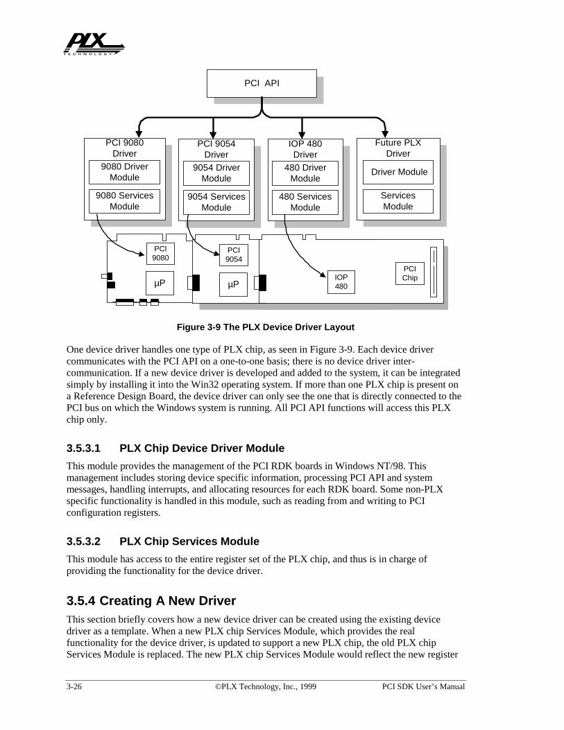
3-26 ©PLX Technology, Inc., 1999 PCI SDK User’s Manual
One device driver handles one type of PLX chip, as seen in Figure 3-9. Each device drivercommunicates with the PCI API on a one-to-one basis; there is no device driver inter-communication. If a new device driver is developed and added to the system, it can be integratedsimply by installing it into the Win32 operating system. If more than one PLX chip is present ona Reference Design Board, the device driver can only see the one that is directly connected to thePCI bus on which the Windows system is running. All PCI API functions will access this PLXchip only.
3.5.3.1 PLX Chip Device Driver Module
This module provides the management of the PCI RDK boards in Windows NT/98. Thismanagement includes storing device specific information, processing PCI API and systemmessages, handling interrupts, and allocating resources for each RDK board. Some non-PLXspecific functionality is handled in this module, such as reading from and writing to PCIconfiguration registers.
3.5.3.2 PLX Chip Services Module
This module has access to the entire register set of the PLX chip, and thus is in charge ofproviding the functionality for the device driver.
3.5.4 Creating A New DriverThis section briefly covers how a new device driver can be created using the existing devicedriver as a template. When a new PLX chip Services Module, which provides the realfunctionality for the device driver, is updated to support a new PLX chip, the old PLX chipServices Module is replaced. The new PLX chip Services Module would reflect the new register
PCI API
9080 ServicesModule
9080 DriverModule
PCI 9080Driver
9054 ServicesModule
9054 DriverModule
PCI 9054Driver
ServicesModule
Driver Module
Future PLXDriver
PCI9080
µP
PCIIC
µP
PCI9054
480 ServicesModule
480 DriverModule
IOP 480Driver
PCIChipIOP
480
Figure 3-9 The PLX Device Driver Layout

PCI SDK User’s Manual ©PLX Technology, Inc., 1999 3-27
set of the PLX chip and would support the existing PCI API by accessing the appropriate registerson the new PLX chip based on the PCI API function requested.
The PLX chip Device Driver Module would need some modifications to create a new PCI devicedriver. When a new API function is introduced, the Device Driver Module has to be modified tosupport the API the function.
3.5.5 Device Driver FeaturesThe Win32 device driver supports the sharing of interrupts between many PLX RDK boards. Thedevice driver uses one interrupt line on the PCI bus that all PLX RDK boards share to interruptthe host PC. The interrupt service routine determines which board caused the interrupt andservices the interrupt from the board.
The device driver supports event logging into the system log file. When the device driverdetermines an error in operation, it updates the system event log file with the appropriateinformation concerning the cause of the error. This log file can be used to debug the device driverwhen the device driver is started at boot time. This file contains the reasons why the device driverwas not loaded and started.
3.5.6 Distribution of PLX Device Drivers and PLXApi.Dll FileA Windows application, which uses PCI API functions from the PCI SDK package, requires 2things:
1. the PlxApi.dll file installed in the system-wide path; and
2. PLX Windows device driver(s) installed properly and started.
It is legal to distribute the PlxApi.dll and device driver files, i.e. Pci9080.sys,Pci9054.sys and Iop480.sys, however it is ILLEGAL to distribute the entire PCI SDKwithout proper authorization by PLX. Customers must choose their own installation methods,such as using InstallShield® software to create installation disks, so that the device driver(s) andthe DLL file can be correctly installed to their designated locations.
3.5.6.1 Installation of PlxApi.dll File
The PlxApi.dll file should be installed to:
• Windows\System directory on Windows 98; or
• WinNT\System32 directory on Windows NT.
Note: “ Windows\” and “ WinNT\” directories mentioned in the above two lines are the defaultinstallation paths for Windows 98 and Windows NT respectively. Therefore, it has to bedetermined at run time by the installation program where the Windows 98 or Windows NTdirectory is really located and it is strongly recommended that the above paths NOT be hard-coded in the installation program. In InstallShield® terminology, the above “Windows\” and“ WinNT\” are denoted as <WINDIR>.
3.5.6.2 Installation of PLX Device Driver
The installation of a device driver involves the following steps:
• Copy relevant files to their proper destination locations; and

3-28 ©PLX Technology, Inc., 1999 PCI SDK User’s Manual
• Set up registry entries on the Windows NT system (Refer to section 2.2.2.2.3 on page 2-12for registry entry description).
3.5.6.2.1 Installation of PLX Device Drivers On Windows NT
1. Copy the device driver file (Pci9080.sys, Pci9054.sys, or Iop480.sys) toWinNT\System32\Drivers directory. The device driver files are located at<INSTALLPATH>\Win32\Driver\WinNT\<DriveName>\i386\free directory, whereDriveName is Pci9080, Pci9054, or Iop480;
2. Add the following registry entries (DriverName = Pci9080, Pci9054, or Iop480)
Under HKEY_LOCAL_MACHINE\System\CurrentControlSet\Services, add:
• Services\<DriverName>\CommonBufferSize = 65536 in decimal, data typeREG_DWORD;
• Services\<DriverName>\ErrorControl = 1, data type REG_DWORD;
• Services\<DriverName>\Start = 2, data type REG_DWORD;
• Services\<DriverName>\Type = 1, data type REG_DWORD;
• Services\<DriverName>\MaxSglTransferSize = 1048576 in decimal, data typeREG_DWORD;
• Services\<DriverName>\MaxPciBus = 3, data type REG_DWORD
• Services\<DriverName>\EventLogLevel = 2, data type REG_DWORD
• Services\<DriverName>\SupportedIDs = Dev0Vend Dev1Vend …, data typeREG_SZ. Dev0 and Dev1 are the four hexadecimal letters for the device IDs, Vend is thefour hexadecimal letters for the vendor ID. One example is “908010B5 040110B5”.One pair of device ID and vendor ID must be separated from another pair by a space.There is no tailing space at the end of the string.
• Control\Session Manager\Memory Management\SystemPages = 80000 indecimal, data type REG_DWORD.
The registry key <DriverName> is the name of the executable without the .sys suffix.
In order for the Event Viewer under Windows NT to retrieve the messages logged by the PLXdevice drivers, the following registry values must be added as well.
Under HKEY_LOCAL_MACHINE\System\CurrentControlSet\Services\ , add:
• EventLog\System\<DriverName>\EventMessageFile =%SystemRoot%\System32\IoLogMsg.dll;%SystemRoot%\System32\drivers\<DriverName>.sys, data type REG_EXPAND_SZ;
• Services\EventLog\System\<DriverName>\TypesSupported = 7, datatype REG_DWORD;
3.5.6.2.2 Installation of PLX Device Drivers On Windows 98
1. Copy the device driver file (Pci9080.sys , Pci9054.sys , or Iop480.sys ) toWindows\System directory. The device driver files are located at

PCI SDK User’s Manual ©PLX Technology, Inc., 1999 3-29
<INSTALLPATH>\Win32\Driver\WDM\<DriveName>\i386\free directory, whereDriveName is Pci9080, Pci9054, or Iop480;
2. Copy the setup information file (INF) PciSdk.inf to Windows\Inf\Other directory.The PciSdk.inf file is in the <INSTALLPATH>\WIN32\Driver\WDM directory.
The PciSdk.inf must be modified first to include customized device and vendor IDs. WhenWindows is rebooted, the operating system will detect a new PCI card and should use the INF fileto assign the correct driver to handle the PCI card. Refer to Windows documentation for INF filesor consult book Inside The Microsoft Windows 98 Registry written by Ghnter Born, published in1998 by Microsoft Press, ISBN 1-57231-824-4.

3-30 ©PLX Technology, Inc., 1999 PCI SDK User’s Manual
This page is intentionally left blank.

PCI SDK User’s Manual ©PLX Technology, Inc., 1999 4-1
4. Real Time Operating System Support
4.1 General InformationThis PCI SDK contains VxWorks BSP for PCI 9054RDK-860 and CompactPCI 9054RDK-860boards. We will provide a VxWorks BSP for IOP 480RDK in the near future. Please send anemail if you are interested in VxWorks BSP for IOP 480RDK to [email protected]
If you are interested in developing a driver for other RTOS, then you can use almost all of theIOP API library functions from this version of the PCI SDK. The IOP API library is a set offunctions that can be called from within a RTOS. The RTOS code needs to call thePlxInitApi() function to initialize the PLX API. This will integrate the IOP API with yourRTOS. You may use this chapter as a reference.
4.2 Getting StartedThis chapter assumes that you are familiar with PLX PCI 9054RDK or CompactPCI 9054RDK-860 reference design boards, PLX PCI SDK 3.0, and WindRiver’s Tornado. Please refer to thePLX PCI 9054RDK-860 Hardware Reference Manual or CompactPCI 9054RDK-860 Hardwarereference Manual for more details about the PLX reference design boards.
4.3 Minimum RequirementsMinimum requirements for the VxWorks IOP Porting Kit Extension for PCI/CPCI 9054RDK-860:
• PLX PCI 9054RDK-860 or CompactPCI 9054RDK-860 reference design board;
• PLX PCI SDK v3.0;
• Windows NT or Windows 98 based PC;
• WindRiver Tornado v1.0.1 or v2.0 Integrated Development Environment;
• Windows HyperTerminal using Xmodem protocol. (Baud rate 38400, 8 data bits, no parity, 1stop bits, no flow control)
4.4 Installation• Turn the power off on your Windows PC.
• Install either the PLX PCI 9054RDK-860 or CompactPCI 9054RDK-860 reference designboard or your PCI 9054 based prototype board in an empty PCI slot in your PC.
• Turn your PC on.
• Install the PLX PCI SDK and the Tornado software, and
• reboot your PC.
Make a plx9054-860 directory in <TORNADO_INSTALLPATH>\tornado\target\config\
directory (TORNADO_INSTALLPATH is where you have installed the Tornado software). The“<INSTALLPATH>\Rtos\VxWorks BSP” contains two folders: “PCI 9054RDK-860” (for the

4-2 ©PLX Technology, Inc., 1999 PCI SDK User’s Manual
PCI 9054RDK-860 board) and “CPCI 9054RDK-860” (for the CompactPCI 9054RDK-860board). Copy the appropriate files from the “<INSTALLPATH>\Rtos\VxWorks BSP”subdirectory into <TORNADO_INSTALLPATH>\tornado\target\config\ directory.
4.5 What’s Included?<TORNADO_INSTALLPATH>\tornado\target\config\plx9054-860 directory will includethe following source code files:
1. API860_vw.a: this is the PLX API library object file.
2. rominit.s, sysalib.s, sysserial.c, ppc860sio.c, syslib.c files initializeand configure the Motorola MPC860, connect SCC1 interrupt handler to handle interruptfrom RXD1 pin in MPC860 port PA15, load VxWorks kernel and setup communicationprotocol with HyperTerminal or Tornado Host Shell.
NOTE:
In rominit.s file insert a line “#define BSP_CPCI9054” for PLX CompactPCI9054RDK-860, insert a line “#undef BSP_CPCI9054” for PCI 9054RDK-860.
3. plxvwdrv1.c, plxvwdrv2.c files initialize and configure the PCI 9054 chip, initialize thePLX API library, DMA resource manager, and connect interrupt handler for externalinterrupt IRQ1 pin in MPC860 from LINTO of PCI 9054 and IDMA2 interrupt handler forIDMA request from DREQ1 in MPC860 Port PC14.
4. plxvwapp1.c, plxvwapp2.c files create the sample test application. These samplesdemonstrate how to use the PLX API library to test Direct Master and DMA capabilities ofthe PCI 9054 chip and IDMA capability of the MPC860.
5. usrconfig.c file: In usrRoot() routine : Insert the line “plxdemo();” before the line“shellInit(..);” in order to run the plxdemo as shown in figure 1. Insert the line“plxinit();” before the line “taskSpawn(..)”, so that PCI 9054 chip will be initializedcorrectly after rebooting vxWorks_rom and it will allow you to download a new flash imageusing PLXMon 99.
6. VxWorks_rom (ELF format) and VxWorks_rom.hex (S record format) are the ROM codethat can communicate with the Tornado Host Shell.
7. VxWorks.res_rom (ELF format) and vxWorks.res_rom.hex (S record format) are thestandalone ROM code, acts as a VxWorks target shell. VxWorks.res_rom code calls theplxdemo program. plxdemo allows you to test the Direct Master, DMA and IDMA featuresfrom the Windows HyperTerminal.
8. makefile is the makefile to make last two set of ROM files.
9. Plxdemo.make creates the vwPlxDemo object file. This file can be loaded from the TornadoHost Shell into the local RAM on the PCI 9054RDK-860 or CompactPCI 9054RDK-860board.
10. Config.h:
• #define TARGET_SHELL to generate vxWorks.res_rom;
• #undef TARGET_SHELL to generate vxWorks_rom.

PCI SDK User’s Manual ©PLX Technology, Inc., 1999 4-3
4.6 Which VxWorks ROM Image Should I Use?Two special versions of the PCI 9054 RDK boot code are provided in the directory<TORNADO_INSTALLPATH>\tornado\target\config\plx9054-860.
1. VxWorks_rom.hex is the ROM code that can communicate with the Tornado Host Shell.
2. VxWorks.res_rom.hex is the standalone ROM code, which acts as a VxWorks target shell.
If you don’t have WindRiver Tornado tools yet, you can follow section 4.7.2.1 to download thevxWorks.res_rom.hex to the reference design board and exercise the plxdemo program fromthe HyperTerminal connected to the serial Port.
If you have WindRiver Tornado tools available, you can follow section 4.7.2.2 to downloadvxWorks_rom.hex, use plxdemo.make to make vwPlxDemo file, download this file to the PCI9054RDK-860’s or CompactPCI 9054RDK-860’s RAM, and execute the plxdemo program fromthe Tornado Shell and Target server console connected to the serial Port.
If you don’t have a PCI 9054RDK-860 or CompactPCI 9054RDK-860 board, and you like tointegrate the PCI 9054 chip into your design, please refer to section 4.5 and make the necessarymodifications to the files listed there.
4.7 PLX VxWorks BSP/PLX API DemonstrationThis section will show the user how to use the PLX VxWorks BSP (Board Support Package),download the VxWorks boot ROM and application program images included in the PLX PCISDK v3.0, and use the PCI 9054 chip under the VxWorks Real Time Operating System (RTOS).
4.7.1 Updating the PCI 9054RDK-860 or CompactPCI 9054RDK-860 onboard FLASHStart the PLXMon 99 utility (included in the PLX PCI SDK). Select Command from the pulldown menu. Click on “Download to IOP”. Choose a file you want to download (please refer tosection 3.3, you can pick either vxWorks_rom.hex or vxWorks.res_rom.hex S record files).Choose “FLASH Device” as your Device Type. Select “S record” as your Image Type. Selectmemory Offset in Hex as “00000” and hit “Download” to update your FLASH to VxWorks bootROM.
Note: It is very important that you refer to PLXMon 99 User’s Manual before reprogramming theFLASH.
4.7.2 PLX API functions DemonstrationThe VxWorks BSP demonstration consists of two parts. The first part assumes that you have noTornado and no Target Server. The second part assumes that you have the Tornado Host Shell.
4.7.2.1 Stand alone VxWorks Target Shell Demo (No Tornado and noTarget Server present)
Update the PCI 9054DK-860’s or CompactPCI 9054RDK-860’s FLASH withvxWorks.res_rom.hex, you can execute the plxdemo without Tornado tools running on yourhost system.

4-4 ©PLX Technology, Inc., 1999 PCI SDK User’s Manual
1. Attach a serial cable from the PCI 9054DK-860 or CompactPCI 9054RDK-860 board to theserial port of the host development system (your PC). The RS232 port communicates viaHyperTerminal using Xmodem protocol. (Baud rate 38400, 8 data bits, no parity, 1 stop bits,no flow control).
Now you can use the plxdemo program from the HyperTerminal as shown in Figure 4-1.You have six options. By selecting 0 through 4,you can run one of the following tests: DirectMaster, Block DMA, SGL DMA, Shuttle DMA, and IDMA. Select 5 to do the multitaskdemo. Select 6 if you want to go into VxWorks target shell.
2. From shell, You can run PLX IOP API functions, examples:
• type "PlxUserWrite(2,0,1)" to turn on PLX RDK LED
• type "PlxUserWrite(2,0,0)" to turn off PLX RDK LED
3. From Shell, type “reboot” as will do a local reset and go back to test menu.
4. This standalone ROM is used purely for demonstration only, You need to get Tornado toolsfrom WindRiver to be able to recompile the sample source programs running under VxWorksRTOS. We will discuss how to modify and recreate new application program in section 4.8.
4.7.2.2 Tornado VxWorks Host Shell Demo
Update the PCI 9054DK-860 or CompactPCI 9054RDK-860 onboard FLASH withvxWorks_rom.hex. You will have Tornado target agent active when you reboot from thisROM. The target agent in the ROM will talk to the Target Server through the serial port.Following steps will guide you through these processes.
Figure 4-1 Stand Alone VxWorks Target Shell Demo Screen

PCI SDK User’s Manual ©PLX Technology, Inc., 1999 4-5
1. Attach a serial cable from the PCI 9054DK-860 or CompactPCI 9054RDK-860 board to theserial port of the host development system. The RS232 port communicates using Baud rate38400, 8 data bits, no parity, 1 stop bits, no flow control.
2. In Host Tornado Integrated Development Environment, select “Tools” from the pull downmenu, choose “Target Server”, then “Configure...” as shown in Figure 4-3.
3. At the “Configure Target Servers” dialog box, enter the following information for the givenfields: - “Description”: Configuration1, “Target Server Name”: plx1.
4. Select the “Change Property” item to be: Back End, and enter the following information forthe given fields: - “Available back Ends”: wdbserial, “Serial Port”: this depends on yoursystem, “Speed”: 38400, “Log File”: User specified.
5. Select the “Change Property” item to be: Core file and symbols, and perform the following,select the “File” radio button, and then<TORNADO_INSTALLPATH>\tornado\target\config\plx9054-860\vxWorks_rom.(Please see Figure 4-4).
Figure 4-2 Reboot the Stand Alone VxWorks Target Shell Demo

4-6 ©PLX Technology, Inc., 1999 PCI SDK User’s Manual
6. Select the “Change Property” item to be: Virtual Console, and select the “use Target ServerWindows as Virtual Console” radio button. See Figure 4-5.
Figure 4-3 Back End Property Page
Figure 4-4 Core File and Symbols Property Page

PCI SDK User’s Manual ©PLX Technology, Inc., 1999 4-7
7. Select the Launch button, the following text window should appear (see Figure 4-6):
8. If the previous output text is displayed, the host tornado target server is successfully talkingto the target agent on the boot ROM and you can continue to step 9. If not, re-check yourconfiguration information and launch the target server again.
Figure 4-5 Virtual Console Property Page
Figure 4-6 Tgtsvr - Console

4-8 ©PLX Technology, Inc., 1999 PCI SDK User’s Manual
Note: If the local bus of the PCI 9054RDK-860 or CompactPCI 9054RDK-860 board ishung, then re-launching the target server will fail. You need to reset the target system if thishappens.
9. In Tornado, select the Tools menu title, and choose the Shell… menu item.
10. At the Shell Launch dialog box, select the OK button.
11. A Shell window should be displayed with a -> prompt, type “lkup”, if you see the symbolsfor PLX IOP API functions listed in PLX PCI SDK (examples: PlxBusPciRead(),PlxDmaIsr(), etc.), you know the PLX vxWorks BSP boot ROM has been installedcorrectly.
12. At the Shell prompt, type “cd <TORNADO_INSTALLPATH>\target\config\plx9054-860”, then perform the following commands to reset standard input, standard output, andstandard error to virtual I/O channel 0 (in our case, it will go to target server console), alsosend logging output to the same virtual device. (refer to WindRiver Tornado User’s guide)
Í vf0=open(“/vio/0”,2,0)
Í ioGlobalStdSet(0,vf0)
Í ioGlobalStdSet(1,vf0)
Í ioGlobalStdSet(2,vf0)
Í logFdAdd(vf0)
or you can type“ < start ” to save some time. (“start” is a script file included )
13. From shell, You can run PLX IOP API functions, examples:
• type "PlxUserWrite(2,0,1)" to turn on PLX RDK LED
• type "PlxUserWrite(2,0,0)" to turn off PLX RDK LED
Figure 4-7 Tornado Shell Prompt

PCI SDK User’s Manual ©PLX Technology, Inc., 1999 4-9
14. At the Shell prompt, type “ld < vwPlxDemo” and press <Enter> key to load the Plx Demoprogram object code into the PCI 9054RDK-860 or CompactPCI 9054RDK-860 on boardRAM. See Figure 4-7.
15. At the Shell prompt ->, type “plxdemo” then press <Enter> key to start executing the PLXdemo program, the target server console will show the main test menu as shown in Figure4-8. From here, you can select from one of the seven choices: Direct Master, Block DMA,SGL DMA, Shuttle DMA, IDMA, multitasking and Exit. Figure 4-9 shows an examplewhere, test #5, Multitasking was selected.
Figure 4-8 Tgtsvr - Console No. 1
Figure 4-9 Tgtsvr - Console No. 2

4-10 ©PLX Technology, Inc., 1999 PCI SDK User’s Manual
4.8 How to rebuild the BSP and Application images?This section will show the user how to rebuild the VxWorks boot ROM, driver and applicationprogram from the source code included in this SDK under the WindRiver Tornado IntegratedDevelopment Environment.
4.8.1 Setup the makefile to build PLX VxWorks Boot ROMCopy the makefile included into the “<TORNADO_INSTALLPATH>\target\config\plx9054-860” directory. Now start the Tornado. You will see the entry “Make PLX9054-860” under theTornado “Project” menu item. Choose “Make Plx9054-860”, then “VxWorks Target”, theneither “vxWorks_rom.hex” to build Host shell version bootrom, or choose“vxWorks.res_rom.hex” to build resident stand alone boot ROM. Other entries are not fullytested in this release.
Note:
1. Modify Config.h to add “#define TARGET_SHELL” and generate vxWorks.res_rom,and add “#undef TARGET_SHELL” to generate vxWorks_rom.
2. In rominit.s insert a line “#define BSP_CPCI9054” for PLX CompactPCI9054RDK-860,insert a line “#undef BSP_CPCI9054” for PCI 9054RDK-860.
4.8.2 Setup the custom project to build PLX demo application1. In Tornado, select the Project menu title.
2. In the Customize Builds dialog box, choose Add button, and Browse button to open theplxdemo.make file, edit the Menu Text window, Build target window as shown in Figure4-10 and Figure 4-11. This completes the setup for building the VxWorks application.
3. “Plxdemo vwPlxDemo” to create application image vwPlxDemo.
Figure 4-10 Customize Builds Screen No. 1

PCI SDK User’s Manual ©PLX Technology, Inc., 1999 4-11
4. “Plxdemo clean” to remove image vwPlxDemo and related object files.
4.9 Tornado 1.0.1 and Tornado 2.0 compatibilityWindRiver provides compatibility between Tornado 2.0 and 1.0.1. However, you may have to dosome minor configuration changes in Tornado 2.0 to make it compatible with Tornado 1.0.1
1. After start Tornado 2.0, go to Tools-Options-Project, Check the ”Show Tornado 1.0.1 menuitem” box, this will causes a customize item “standard BSP Build” to be added to the Build
Figure 4-11 Customize Builds Screen No. 2
Figure 4-12 Options

4-12 ©PLX Technology, Inc., 1999 PCI SDK User’s Manual
menu. This allows you to perform Tornado 1.0.1-style builds in BSP directories, to useexisting Tornado 1.0.1-style Build menu items, and to create additional Build menucustomizations. (Figure 4-12)
2. Copy and modify usrconfig.c file from<TORNADO_INSTALLPATH>\tornado20\target\config\all.
3. Tornado supports virtual I/O to the host from target applications. “Redirect target I/O“redirect the target global stdin,stdout, and stderr to the target server. “Create ConsoleWindow” create a virtual console window on the target server host for target I/O. “Redirecttarget Shell” starts a console window into which the target shell’s standard input,output, anderror will be redirected.
Figure 4-13 Build VxWorks

PCI SDK User’s Manual ©PLX Technology, Inc., 1999 4-13
Figure 4-14 Configure Target Servers

4-14 ©PLX Technology, Inc., 1999 PCI SDK User’s Manual
This page is intentionally left blank.

PCI SDK User’s Manual ©PLX Technology, Inc., 1999 5-1
5. RDK Software Quick ReferenceThe information below should be used as a guide to the PCI SDK software requirements for eachPLX RDK board.
5.1 IOP 480RDKThe table below describes the memory requirements of the PCI SDK for the IOP 480RDK.
Item IOP 480RDK
SDRAM Address 0x0000 0000 –> 0x01FF FFFF(32MB)
FLASH Type ATMEL AT49LV040
FLASH Address 0xFFF8 0000 –> 0xFFFF FFFF(512KB)
FLASH Image Offset at which toreprogram the FLASH
0x0006 0000 (If the user has abigger FLASH image, this has tobe decreased to proper offset.)
EEPROM Type 93CS66LEN
Memory space used by ROM code 0x0000 0000 –> 0x0003 FFFF
Memory space used by RAM code(PCI SDK Samples)
0x0004 0000 –> 0x0007 FFFF
Direct Master to PCI memoryspace Address
0x4000 0000 –> 0x4FFF FFFF(256MB)
Direct Master to PCI IO spaceAddress
0x5000 0000 –> 0x5FFF FFFF(256MB)
IOP 480 Configuration RegisterBase Address
0x5000 0000 (default and EEPROMsettings)
IOP 480 Configuration RegisterBase Address in PCI SDK
0x3000 0000 (re-initialized fromdefault and used in SDK)
IOP 480 Serial Port Unit BaseAddress
0x1000 0000
Memory space recommend foruser’s use.
0x0008 0000 -> 0x01FF FFFF(31.5MB)
Users, who have upgraded the PCI SDK and intend to use it with an existing PLX RDK, mustfirst reprogram the configuration EEPROM connected to the PLX chip. Skipping this step cancause unpredictable behavior of the PCI SDK. If you have purchased the PCI SDK with a PLXRDK then there is no need to upgrade the EEPROM because it was programmed at the factorybefore shipping. The following diagram shows the default EEPROM settings for the RDK.
Table 5-1. Basic Information About IOP 480RDK

5-2 ©PLX Technology, Inc., 1999 PCI SDK User’s Manual
5.2 PCI 9054RDK-860The table below describes the memory requirements of the PCI SDK for the PCI 9054RDK-860.
Item PCI 9054RDK-860
SDRAM Address 0x0000 0000 –> 0x01FF FFFF(32MB)
FLASH Type AT49LV040(default as shipped)
AM29F040 also supported insoftware
FLASH Address 0xFFF0 0000 –> 0xFFF7 FFFF(512KB)
FLASH Image Offset at which toreprogram the FLASH
0x0000 0000
Memory space used by ROM code 0x0000 0000 –> 0x0003 FFFF
Memory space used by RAM code(PCI SDK Samples)
0x0004 0000 –> 0x0007 FFFF
Direct Master to PCI memory 0x4000 0000 –> 0x40FF FFFF
Figure 5-1. Configuration EEPROM Settings for the IOP 480RDK
Table 5-2. Basic Information About PCI 9054RDK-860

PCI SDK User’s Manual ©PLX Technology, Inc., 1999 5-3
Item PCI 9054RDK-860
space Address (16MB)
Direct Master to PCI IO spaceAddress
0x5000 0000 –> 0x50FF FFFF(16MB)
PCI 9054 Register Address 0x3000 0000 -> 0x3000 01FF
Memory space recommend foruser’s use.
0x0008 0000 -> 0x01FF FFFF(31.5MB)
Users, who have upgraded the PCI SDK and intend to use it with an existing PLX RDK, mustfirst reprogram the configuration EEPROM connected to the PLX chip. Skipping this step cancause unpredictable behavior of the PCI SDK. If you have purchased the PCI SDK with a PLXRDK then there is no need to upgrade the EEPROM because it was programmed at the factorybefore shipping. The following diagram shows the default settings for the RDK.
5.3 CompactPCI 9054RDK-860The table below describes the memory requirements of the PCI SDK for the CompactPCI9054RDK-860.
Figure 5-2. Configuration EEPROM Settings for the PCI 9054RDK-860

5-4 ©PLX Technology, Inc., 1999 PCI SDK User’s Manual
Item CompactPCI 9054RDK-860
SDRAM Address 0x0000 0000 –> 0x01FF FFFF(32MB)
SBSRAM Address 0x2000 0000 –> 0x2007 FFFF(512KB)
FLASH Type AT49LV040(default as shipped)
AM29F040 also supported insoftware
FLASH Address 0xFFF0 0000 –> 0xFFF7 FFFF(512KB)
FLASH Image Offset at which toreprogram the FLASH
0x0000 0000
Memory space used by ROM code 0x0000 0000 –> 0x0003 FFFF
Memory space used by RAM code(PCI SDK Samples)
0x0004 0000 –> 0x0007 FFFF
Direct Master to PCI memoryspace Address
0x4000 0000 –> 0x40FF FFFF(16MB)
Direct Master to PCI IO spaceAddress
0x5000 0000 –> 0x50FF FFFF(16MB)
PCI 9054 Register Address 0x3000 0000 -> 0x3000 01FF
Memory space recommend foruser’s use.
0x0008 0000 -> 0x01FF FFFF(31.5MB)
Users, who have upgraded the PCI SDK and intend to use it with an existing PLX RDK, mustfirst reprogram the configuration EEPROM connected to the PLX chip. Skipping this step cancause unpredictable behavior of the PCI SDK. If you have purchased the PCI SDK with a PLXRDK then there is no need to upgrade the EEPROM because it was programmed at the factorybefore shipping. The following diagram shows the default settings for the RDK.
Table 5-3. Basic Information About CompactPCI 9054RDK-860

PCI SDK User’s Manual ©PLX Technology, Inc., 1999 5-5
5.4 PCI 9080RDK-401BThe table below describes the memory requirements of the PCI SDK for the PCI 9080RDK-401B.
Item PCI 9080RDK-401B
SDRAM Address 0x0000 0000 –> 0x00FF FFFF(16MB)
SRAM Address 0x1000 0000 –> 0x1007 FFFF(512KB)
FLASH Type AM29F040
FLASH Address 0xFFF8 0000 –> 0xFFFF FFFF(512KB)
FLASH Image Offset at which toreprogram the FLASH
0x0006 0000 (If the user has abigger FLASH image, this has tobe decreased to proper offset.)
Memory space used by ROM code 0x1000 0000 –> 0x1003 FFFF
Memory space used by RAM code 0x1004 0000 –> 0x1007 FFFF
Figure 5-3. Configuration EEPROM Settings for the CompatctPCI 9054RDK-860
Table 5-4. Basic Information About PCI 9080RDK-401B

5-6 ©PLX Technology, Inc., 1999 PCI SDK User’s Manual
Item PCI 9080RDK-401B
(PCI SDK Samples)
Direct Master to PCI memoryspace Address
0xB800 0000 –> 0xBFFF FFFF(8MB)
Direct Master to PCI IO spaceAddress
0xB000 0000 –> 0xB7FF FFFF(8MB)
PCI 9080 Register Address 0x2000 0000 -> 0x2000 01FF
Memory space recommend foruser’s use.
0x0 -> 0x00FF FFFF (16MB)
Users, who have upgraded the PCI SDK and intend to use it with an existing PLX RDK, mustfirst reprogram the configuration EEPROM connected to the PLX chip. Skipping this step cancause unpredictable behavior of the PCI SDK. If you have purchased the PCI SDK with a PLXRDK then there is no need to upgrade the EEPROM because it was programmed at the factorybefore shipping. The following diagram shows the default settings for the RDK.
5.5 PCI 9080RDK-860The table below describes the memory requirements of the PCI SDK for the PCI 9080RDK-860.
Figure 5-4. Configuration EEPROM Settings for the PCI 9080RDK-401B

PCI SDK User’s Manual ©PLX Technology, Inc., 1999 5-7
Item PCI 9080RDK-860
DRAM Address 0x1000 0000 –> 0x10FF FFFF(16MB)
SRAM Address 0x0000 0000 –> 0x0007 FFFF(512KB)
FLASH Type AM29F040 (IOP programming only)
FLASH Address 0xFFF8 0000 –> 0xFFFF FFFF(512KB)
FLASH Image Offset at which toreprogram the FLASH
0x0000 0000
Memory space used by ROM code 0x0000 0000 –> 0x0003 FFFF
Memory space used by RAM code(PCI SDK Samples)
0x0004 0000 –> 0x0007 FFFF
Direct Master to PCI memoryspace Address
0x4000 0000 –> 0x40FF FFFF(16MB)
Direct Master to PCI IO spaceAddress
0x5000 0000 –> 0x50FF FFFF(16MB)
PCI 9080 Register Address 0xC000 0000 -> 0xC000 01FF
Memory space recommend foruser’s use.
0x1000 0000 -> 0x10FF FFFF(16MB)
Users, who have upgraded the PCI SDK and intend to use it with an existing PLX RDK, mustfirst reprogram the configuration EEPROM connected to the PLX chip. Skipping this step cancause unpredictable behavior of the PCI SDK. If you have purchased the PCI SDK with a PLXRDK then there is no need to upgrade the EEPROM because it was programmed at the factorybefore shipping. The following diagram shows the default settings for the RDK.
Table 5-5. Basic Information About PCI 9080RDK-860

5-8 ©PLX Technology, Inc., 1999 PCI SDK User’s Manual
5.6 PCI 9080RDK-SH3The table below describes the memory requirements of the PCI SDK for the PCI 9080RDK-SH3.
Item PCI 9080RDK-SH3
DRAM Address for SH3 access 0x0C00 0000 –> 0x0CFF FFFF (16MB)
DRAM Address for PCI 9080access
Not Supported
SRAM Address for SH3 access 0x0900 0000 –> 0x0903 FFFF (256KB)
SRAM Address for PCI 9080access
0x4000 0000 –> 0x4003 FFFF (256KB)
EPROM Type TMS27C010A-10
EPROM Address for SH3 access(if boot device)
0x0000 0000 –> 0x0001 FFFF (256KB)
EPROM Address for PCI 9080access
Not Supported
FLASH Type MBM29LV160B-90
FLASH Address for SH3 access 0x0000 0000 –> 0x001F FFFF (2MB)
Figure 5-5. Configuration EEPROM Settings for the PCI 9080RDK-860
Table 5-6. Basic Information About PCI 9080RDK-SH3

PCI SDK User’s Manual ©PLX Technology, Inc., 1999 5-9
Item PCI 9080RDK-SH3
(if boot device)
FLASH Address for SH3 access(if non-boot device)
0x0100 0000 –> 0x011F FFFF (2MB)
FLASH Address for PCI 9080access
Not Supported
FLASH Image Offset at which toreprogram the FLASH
0x0000 0000
Memory space used by ROM code 0x0C00 0000 –> 0x0C03 FFFF and
0x0900 0000 -> 0x0900 0FFF
Memory space used by RAM code(PCI SDK Samples)
0x0900 1000 –> 0x0900 FFFF
Direct Master to PCI memoryspace Address for SH3 access
0x0A00 0000 –> 0x0A0F FFFF (1MB)
Direct Master to PCI IO spaceAddress for SH3 access
0x0B00 0000 –> 0x0B0F FFFF (1MB)
PCI 9080 Register Address forSH3 access
0x0800 0000 -> 0x0800 01FF
Memory space recommended foruser’s use for SH3 access.
0x0901 0000 -> 0x0903 FFFF (192KB)
Memory space recommended foruser’s use for PCI 9080 access.
0x4001 0000 -> 0x4003 FFFF (192KB)
Users, who have upgraded the PCI SDK and intend to use it with an existing PLX RDK, mustfirst reprogram the configuration EEPROM connected to the PLX chip. Skipping this step cancause unpredictable behavior of the PCI SDK. If you have purchased the PCI SDK with a PLXRDK then there is no need to upgrade the EEPROM because it was programmed at the factorybefore shipping. The following diagram shows the default settings for the RDK.

5-10 ©PLX Technology, Inc., 1999 PCI SDK User’s Manual
5.7 PCI 9080RDK-RC32364The table below describes the memory requirements of the PCI SDK for the PCI 9080RDK-RC32364.
Item PCI 9080RDK-RC32364
DRAM Virtual Address 0x0010 0000 –> 0x004F FFFF(4MB)
SRAM Virtual Address 0x0000 0000 –> 0x000F FFFF(1MB)
EPROM Type M27C801-100
EPROM Virtual Address 0xBFC0 0000 –> 0xBFC7 FFFF(512KB)
EPROM Image Base Address 0x0000 0000
Virtual memory space used byROM code
0x0000 0000 –> 0x0003 FFFF
Virtual memory space used byRAM code (PCI SDK Samples)
0x0004 0000 –> 0x0007 FFFF
Direct Master to PCI memory 0x1500 0000 –> 0x15FF FFFF
Figure 5-6. Configuration EEPROM Settings for the PCI 9080RDK-SH3
Table 5-7. Basic Information About PCI 9080RDK-RC32364

PCI SDK User’s Manual ©PLX Technology, Inc., 1999 5-11
Item PCI 9080RDK-RC32364
virtual space Address (16MB)
Direct Master to PCI IO virtualspace Address
0x1600 0000 –> 0x16FF FFFF(16MB)
PCI 9080 Register VirtualAddress
0x1400 0000 -> 0x1400 01FF
Virtual Memory space recommendfor user’s use.
0x0008 0000 -> 0x004F FFFF(4.5MB)
Due to hardware design, the configuration EEPROM on this RDK does not work. So, theconfiguration EEPROM is not provided. However, the original hardware design for the serialEEPROM is 93CS56.

5-12 ©PLX Technology, Inc., 1999 PCI SDK User’s Manual
This page is intentionally left blank.

PCI SDK User’s Manual ©PLX Technology, Inc., 1999 I
Appendix A. Index
A
AppMain............................... 3-6, 3-7, 3-20, 3-21
B
BEM ....................................................................3-2, 3-3, 3-12, 3-13, 3-14, 3-15, 3-16, 3-17, 3-19, 3-20, 3-21
BemMain ...............................................3-7, 3-20Block DMA .......................... 3-8, 3-9, 3-10, 3-12Boot up code...................................2-7, 3-5, 3-22BSP......................................................................
1-1, 2-4, 2-17, 3-1, 3-2, 3-3, 3-4, 3-5, 3-6, 3-7,3-12, 3-21, 3-22, 3-23
C
CompactPCI.............................. 1-3, 2-5, 5-3, 5-4
D
Diab Data, Inc. Compiler..................1-3, 2-7, 2-8Direct Master .......................................................
3-6, 5-1, 5-2, 5-3, 5-4, 5-6, 5-7, 5-9, 5-10, 5-11
Direct Slave .................................................. 2-17
E
Endian............................................................. 3-1Exception vector table .................................... 3-5
G
GNU compiler .........................................1-3, 2-7
I
I2O................................................................... 1-1IBM 401 EVB................................................. 1-3IBM High C/C++ PowerPC Cross-Compiler . 1-3IDT/c Cross Compiler.......................1-3, 2-7, 2-8IOP 480................................................................
1-2, 1-3, 2-4, 2-10, 2-13, 2-14, 2-16, 3-8, 3-13, 3-14, 3-16, 3-17, 3-19, 5-1
IOP 480RDK ................................... 1-3, 2-7, 5-1ISR ...................................... 3-5, 3-10, 3-11, 3-23
L
LED................................................ 2-7, 3-1, 3-22
M
Microprocessor ................................ 1-4, 3-4, 3-5MiniBSP ............................... 2-6, 2-17, 3-5, 3-22MPC860......................................... 1-3, 2-7, 2-17
P
PCI 9054RDK-860 .......................... 1-3, 2-5, 5-2PCI 9080RDK-401B........................ 1-3, 2-5, 5-5PCI 9080RDK-860 ................... 1-3, 2-5, 5-6, 5-7PCI 9080RDK-RC32364 ........ 1-3, 2-5, 2-7, 5-10PCI 9080RDK-SH3 .................. 1-3, 2-5, 2-7, 5-8PCI API DLL.........................................3-3, 3-25PCI BIOS.................................................2-5, 3-6PLXMon 99 .........................................................
...1-1, 1-2, 2-1, 2-4, 2-5, 2-6, 2-10, 2-11, 2-14, 2-17, 3-1, 3-3, 3-7, 3-12, 3-20, 3-21, 3-24, 3-25
Power Management ......................................2-16Protocols .......................................................3-14
R
Registry........................................ 2-5, 2-12, 2-16
S
SGL DMA ..................................... 2-16, 3-8, 3-9Shuttle DMA................2-14, 2-16, 3-8, 3-9, 3-11
U
UART ..........................3-6, 3-7, 3-12, 3-21, 3-23
W
WDM ........................................... 2-1, 2-10, 3-25

II ©PLX Technology, Inc., 1999 PCI SDK User’s Manual
This page is intentionally left blank.