
Paul D. Sclavounos, MIT, Dept. of Ocean Engineering ...
32
TANK TESTING VS COMPUTATIONAL FLUID DYNAMICS CFD! IN SHIP DESIGN Paul D. Sclavounos, MIT, Dept.of Ocean Engineering, Cambridge MA 5ungeun Kim, Boston Marine Consulting Inc., Cambridge AA L Introduction Computational fluid dynamics CFD! isplaying an increasingly important role as a tool in ship design. The last two decades have witnessed rapid growth in the development of computational algorithtns forthe simulation of a broad variety of ship f1ows. Fueled by the advent fast micro- processors, ship fiow computer programs are progressively finding their way to desktop PC's and into the toolbox of naval architects. Tank testing isa necessary step in ship design and this state of affairs isunlikely to be seriously challenged inthe near future, Yet, the frequency and extent to which tank testing islikely tobe used will be challenged bycomputational methods which have been properly verified- debugged, validated compared to physical results, accredited- accepted as valid design tools and transitioned - used bypeople other than their developers. A survey of such methods in various stages ofdevelopment was presented byBeck, Reed and Rood 996! [1].Larsson and Baba 996! [2]presented a review of the use of viscous CFD in predicting the ship wake and resistance. Recent progress towards the computation of potential flow wave ship interactions isreviewed by Sclavounos 996! [3]. The present article isnot intended to be a survey of ship flow computational methods orof theattributes of their respective solution algorithms. Interested readers should refer to the articles listedabove andthe references therein. Instead this studywiII address areas in ship hydrodynamic design where CFD has made considerable inroads. The primary accomplishments and challenges faced by computation will be identifled. Finally, emphasis will be placed on the ship flow computational method SWAN Ship Wave ANalysis! developed by the authors and their associates [cf.Sclavounos et. al. 996'! [4]]. Several of itsapplications in ship design will be discussed. The paper isorganized as follows, A variety of ship flows of interest indesign are identified and a general discussion of the successes and challenges faced by tank testing and CFD iscarried out. Various types of ship hulls are identified and theperformance and use of specific computational methods in theirhydrodynamic design is addressed. 2. Ship Wave Pattern Knowledge ofthe ship wave pattern via tank testing or CFD isimportant in ship design in a variety of ways. For example, the accurate prediction of the wake trailing a ship isessential forthe evaluation of the ship wave resistance, The ship wake and itssignature are essential attributes of modern naval hull forms. Moreover, the wave elevation along the waterline of high-speed vessels may play animportant rolein the design of the ship waterjet propulsion units. The ship wave pattern isaffected both byviscous and ideal effects. Along most of the ship waterline and away from the ship wake, the ship Kelvin wave pattern may be modeled byassuming that water is anideal fluid,Near theship stern and in itswake, vorticity generated within theship boundary layer, the propulsion mechanism and by the stern geometry plays an important role in defining the ship surface wake. 325
Transcript of Paul D. Sclavounos, MIT, Dept. of Ocean Engineering ...

TANK TESTING VS COMPUTATIONAL FLUID DYNAMICS CFD!IN SHIP DESIGN
Paul D. Sclavounos, MIT, Dept. of Ocean Engineering, Cambridge MA5ungeun Kim, Boston Marine Consulting Inc., Cambridge AA
L Introduction
Computational fluid dynamics CFD! is playing an increasingly important role as a tool inship design. The last two decades have witnessed rapid growth in the development of computationalalgorithtns for the simulation of a broad variety of ship f1ows. Fueled by the advent fast micro-processors, ship fiow computer programs are progressively finding their way to desktop PC's andinto the toolbox of naval architects.
Tank testing is a necessary step in ship design and this state of affairs is unlikely to beseriously challenged in the near future, Yet, the frequency and extent to which tank testing is likelyto be used will be challenged by computational methods which have been properly verified-debugged, validated � compared to physical results, accredited- accepted as valid design tools andtransitioned - used by people other than their developers. A survey of such methods in variousstages of development was presented by Beck, Reed and Rood �996! [1]. Larsson and Baba �996![2] presented a review of the use of viscous CFD in predicting the ship wake and resistance. Recentprogress towards the computation of potential flow wave ship interactions is reviewed bySclavounos �996! [3].
The present article is not intended to be a survey of ship flow computational methods or ofthe attributes of their respective solution algorithms. Interested readers should refer to the articleslisted above and the references therein. Instead this study wiII address areas in ship hydrodynamicdesign where CFD has made considerable inroads. The primary accomplishments and challengesfaced by computation will be identifled. Finally, emphasis will be placed on the ship flowcomputational method SWAN Ship Wave ANalysis! developed by the authors and their associates[cf. Sclavounos et. al. �996'! [4]]. Several of its applications in ship design will be discussed.
The paper is organized as follows, A variety of ship flows of interest in design are identifiedand a general discussion of the successes and challenges faced by tank testing and CFD is carriedout. Various types of ship hulls are identified and the performance and use of specificcomputational methods in their hydrodynamic design is addressed.
2. Ship Wave Pattern
Knowledge of the ship wave pattern via tank testing or CFD is important in ship design in avariety of ways. For example, the accurate prediction of the wake trailing a ship is essential for theevaluation of the ship wave resistance, The ship wake and its signature are essential attributes ofmodern naval hull forms. Moreover, the wave elevation along the waterline of high-speed vesselsmay play an important role in the design of the ship waterjet propulsion units.
The ship wave pattern is affected both by viscous and ideal effects. Along most of the shipwaterline and away from the ship wake, the ship Kelvin wave pattern may be modeled by assumingthat water is an ideal fluid, Near the ship stern and in its wake, vorticity generated within the shipboundary layer, the propulsion mechanism and by the stern geometry plays an important role indefining the ship surface wake.
325
2,1 Tank Testing
Tank tests are effective in evaluating ship wakes since the wave elevation over the entirefree surface may be easily measured by a variety of experimental techniques. The challenge facedby experiments is the scaling of the measured ship wake to full scale, where the high Reynoldsnumber alters appreciably the properties and evolution of the free surface turbulent flow comparedto laboratory measurements. The comparison of laboratory and full-scale ship wakes is necessaryfor the development ofbetter scahng laws.
The measurement of the portion of the ship wave pattern not affected appreciably by viscouseffects is very reliable and is widely used to verify and validate CFD methods, discussed next.
2.2 CFD
~ 0 0200 012G
0 O'15
0 0100 GC40
0 000-0 0040
-0 GMG
.0 012C
0 015 4 35 .5 .2 .2 -1 5 -1.040 %20 000 02C 04Cx/L
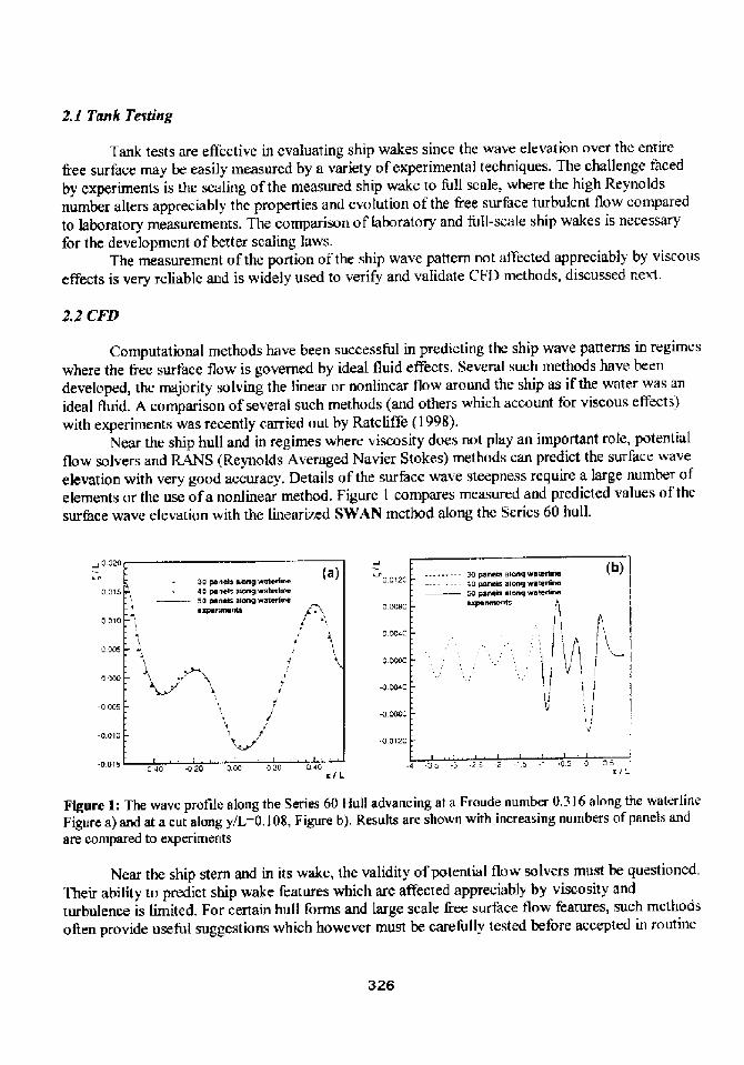
Figure 1: The wave profile along the Series 60 Hull advancing at a Froude number 0.316 along the waterlineFigure a! and at a cut along y/L&,108, Figure b!. Results are shown with increasing numbers of panels andare compared to experiments
Near the ship stern and in its wake, the validity of potential flow solvers must be questioned,Their ability to predict ship wake features which are affected appreciably by viscosity andturbulence is limited, For certain hull forms and large scale &ee surface flow features, such methodsoken provide useful suggestions which however must be carefully tested before accepted in routine
326
Computational methods have been successful in predicting the ship wave patterns in regimeswhere the free surface flow is governed by ideal fluid effects. Several such methods have beendeveloped, the majority solving the 1inear or nonlinear flow around the ship as if the water was anideal fluid. A comparison of several such methods and others which account for viscous effects!with experiments was recently carried out by Ratcliffe �998!.
Near the ship hull and in regimes where viscosity does not play an important role, potentialflow solvers and RANS Reynolds Averaged Navier Stokes! methods can predict the surface waveelevation with very good accuracy, Details of the surface wave steepness require a large number ofelements or the use of a nonlinear method. Figure 1 compares measured and predicted values of thesurface wave elevation with the linearized SWAN method along the Series 60 hull.

design. A number of methods which account for viscous and free surface etfects are underdevelopment for this purpose.
Far from the ship and in regimes where viscosity is not important, potential flaw methodswhich solve the free surface flow equations without introducing numerical dissipation have beenvery successful in predicting the ship Kelvin wake. Figure 2 compares predictions of SWAN-1 withKelvin wake measurements by Lindenmuth, Ratcliffc and Reed �991! for a naval combatantknown as the 541S Hull.
v L
Figure 2i Contour plot of the v ave proflIe around the 54 I 5 hull advancing at a Froude number 0.4I. Thebottom ha1f of the figure compares the measured and predicted kelvin wake spectrum as a function of thewavenumber
Several interesting conclusions may be drawn from this comparison, supporting the SWAN-1 predictions on one hand and pointing to its limitations on the other. The SWA%-1 Kelvin wakecomputations may be seen to converge w ith increasing numbers of panels and to be capable tobetter resolve flow details as the mesh density increases. Moreover, the measured and predictedKelvin wake spectra, plotted at the bottom of the figure, are seen to agree well over-the smalI andmoderate wavenumber regime. The agreement over the short wavenurnber regime is not satisfactoryand is attributed to viscous and nonlinear effects arising from the ship wake where free-surfaceturbulence can no longer be ignored,
Related to the ship wave pattern measurement and prediction, is the evaluation of the shipnominal and effective wake for use to design ship propulsors. The literature on this subject isextensive and this subject will not be addressed in the present article. However, it is worth noting
327

that most of the RANS methods under development for the prediction of the ship wake, areevolutions of methods originally develo~ for the prediction of ship propeller wakes.
3. Sbip Resistance
The evaluation of the resistance of a ship by analytical or computational means remains theHoly Grail of ship hydrodynamics. Since the l 898 Mitchell thin-ship theory and a century ofadvances in theoretical and computational ship hydrodynamics, the evaluation of the resistance o fmany vessels with the accuracy demanded by industry is still the purview of tank testing,
However, while modern CFD methods are not capable to predict the ship service speed towithin a &action of a knot, they may offer valuable assistance to the ship designer on how tominimize ship resistance and improve hull form design.
Here, it is necessary to defme and discuss the resistance components of conventional andhigh-performance ship hulls, and identify those that stand to benefit from improved tank testingtechniques and CFD methods,
3. S Frictiona 8esisianee
This is the resistance component obtained by treating the wetted surface of the ship hull as aflat plate and using the lT'1C friction Line for the relevant Reynolds number to evaluate thekictional drag. Areas where CFD may improve the prediction of the frictional resistance is in theevaluation of the ship wetted surface which may differ appreciably from its static value for hullswith overhangs at the bow an stern. This is typically the case in sailing yacht design,
The frictional resistance evaluated as defined above, is largely dependent on the Reynoldsnumber and to a far lesser extent on the Froude number. The latter dependence arises from thevariation of the ship wetted surface and the influence of the Froude number upon the FormResistance, discussed below. The frictional resistance using the static wetted surface is oAensubtracted Rom the total niodel resistance measured in tank tests, in order to obtain the remainder,often referred to as the Residuary Resistance.
The contribution of CFD in this process is to better predict the dynamic wetted surface andon certain occasions the influence of wave effects upon the form factor. Both these effects arecomplex to identi fy via pure tank testing,
3.Z Residuary Resistance
The simplest definition of the Residuary Resistance, adopted in the present article, is thedifference of the total resistance and the flat plate fictional resistance evaluated using the staticwetted surface. Under this definition the kictional resistance is purely Reynolds number dependent,with all Froude and some Reynolds number effects transferred to the Residuary Resistance. If thedynamic wetted surface is used, e.g. estimated by a CFD method, some Froude number effects areincluded in the frictional resistance,
Tank testing, ofien evaluates the Residuary Resistance as described above, namely using thestatic wetted surface to determine the frictional component, On certain occasions dynamic effectsmay be accounted for by sinking and trimming the model to their values at the vessel cruisingspeed. Thereafter, it is left with the ship designer to identify the various components of theResiduary Resistance, either via further tank testing, e.g. low-Froude number runs to determine the
328

form resistance using Prohska's method, experience or CFD. AII these are discussed in more detailbelow. The primary components of the Residuarv Resistance are:
a Wave Resistancea Form Resistance
a Induced Resistance
3,3 Wave Resisraace
The wave resistance is defined as the component of the Residuary Resistance which dependsprimarily on ideal fiuid effects and is therefore Froude number dependent. 'I his is the component ofresistance which may be evaluated by standalone potential flow CFD methods, When available viacomputation, the wave resistance may be of great value to the designer particularly for ship hu! lscruising at high speeds.
Identifying with accuracy the wave resistance from a tank measurement is not easy, unlessthe form and residuary resistance components are known for similar hulls, experience or furthertank testing. As discussed below, this may not always be a feasible or inexpensive task,
Therefore. the evaluation of the wave resistance from linear or nonlinear potential flow CFDmethods is of great value to ship designers. Several such linearized and some nonlinear methodshave been developed and have shown considerable promise in evaluating the wave resistance ofcruiser and transom stern ships. as well as sailing yachts cf, [3],[4]].
A fully nonlinear potential flow solution will generally produce a more accurate predictionof the wave resistance. However. equally important to the selection of a nonlinear wave resistancemethod, is the development of a robust solution algorithm. Discretization errors must be identifiedand controlled via systematic convergence tests for a base linearized method, prior to an attempt toinclude nonlinear effects which are often delicate to model numerically.
Moreover, from the point of a view of the ship designer, it is important to identify thevarious sources of nonlinearity in the wave resistance of ships. At moderate and high speeds theyare:
a Vessel sinkage and trimcr Nonlinear Variation of the Ship Wetted Surface
Nonlinear Variation of Pressure along the Ship Hull
Several of these effects may be approximated with good accuracy by linearized methods likeSWAN. The vessel sinkage and trim and the respective wave resistance may bc determined fromthe iterated execution of a linearized CFD method. Thc same applies to the approximation of thenonlinear variation of the ship wetted surface, Finally, a wave resistance method like SWAN, whichdoes not introduce numerical dissipation into the computation of the surface wave profile, may beused to evaluate the wave resistance &om a wave cut analysis [cf. Nakos and Sclavounos �993!].This technique was pioneered by Eggers, Sharma and Ward �967! as a very reliable means ofidentifying the ship wave resistance experimentally.
Later in this section the implementation of the techniques discussed above will bedemonstrated with the linearized potential flow CFD method SWAN for the evaluation of theResiduary Resrstance of ships, including nonlinear effects,
However, the comparison of these SWAN CFD predictions with experiments is prematurebefore the two remaining components of resistance are discussed. In ship design, an effort toevaluate the ship wave resistance with a CFD method with high accuracy is often misguided when
329

the Form and Residuary Resistance components are important and often hard to determine throughtank testing or via the use of CFD methods.
3.4 Form Resistance
It is common practice in the marine hydrodynamics and ship design literature to define thiscomponent of resistance as the remainder when the sum o f the Frictional and Wave Resistance asdefined above, are subtracted from the total resistance measured in a tank test.
For conventional ships which cruiser stems, the Form Resistance is often a small yetimportant component which scales primarily with the Reynolds number. This is the fundamentalassumption of Froude's scaling law which is widely practiced with success by the ship designcommunity, especially for ships with conventional hull shapes cruising at moderate speeds.
The precise determination of the Farm Resistance, or its form factor, is far from a trivial taskeither experimentally or by using advanced infinite flow CFD methods. The Form Resistancedepends critically on the viscous and turbulent flaw features near the ship stern, which are known tovary drastically for various hull forms and stern shapes. Moreover, at high speeds the FormResistance gains a dependence on the Froude number due to the influence of free surface effectsupon the Frictional Resistance through the variation of the wetted surface! and upon the viscousflow features near the ship stern,
Therefore, the estimation of the Form Resistance via tank testing is oAen more art 1.hanscience, particularly when it comes to the scaling of tank measurements of resistance to the fullscale vessel. Through experience, experimental facilities have developed empirical methods toaccurately determine the Form Resistance for classes of ships or sailing yachts, the full scaleperformance of which is known, This experience is aAen translated into a correlation caeflicientwhich when included into the scaling law produces full scale values of the ship resistance oreffective horsepower acceptable by industry.
Similar empiricism is frequently present but not widely advertised in CFD methods,particularly when it comes to the selection of the solution algorithm and the choice of thecorresponding discretization parameters, It is the authors' view that such empiricism in CFD isjustifiabl, as long as it is practiced in an open manner. The free surface flows treated by the currentCFD methods are complex and the marine hydrodynamics and ship design community stand to bothbenefit from an open communication on the degree to which empiricism is practiced both inexperiments and computation.
3.5 Induced Resistance
The Form Resistance of high-speed vessels with streamlined huHs and transom stems ariseslargely from the flow separation around the transom section. Vorticity is generated and shed on thefree surface and the ship wake generating a coinponent of drag which may be significant anddepends critically on the ship speed and the design of the stern region. Because of the evidentanalogy to the origins of the induced resistance of three dimensional lifting surfaces, thc FormResistance is for this class of vessels is here referred to as Induced Resistance,
There exists no clear demarcation between the stern shapes for which the fluid mechanicsdescribed in the previous paragraph becomes dominant, relative to the fluid mechanics responsiblefor the more conventional Form Resistance discussed in the previous section. Yet, for the class afhigh-speed mono or multi-hull vessels with transom stems the classification of this component asInduced Resistance is more appealing.
330

!t is clear that a portion of the Induced Resistance as defined above, belongs to the WaveResistance as evaluated by potential flow CFD methods or via wave cut analysis in tank testing.Yet, the significant portion of it which is of viscous origin cannot be accounted for by a linear ornonlinear potential flow solver, This becomes evident from the discrepancy between tankmeasurements of the total resistance relative to the sum of the Frictional Resistance and the WaveResistance evaluated by potential flow CFD methods like SWAN. This difference, defined here asthe Induced Resistance, depends on both viscous and free surface effects and therefore must scalewith both the Reynolds and Froude numbers,Extrapolating the Induced Resistance to full scale remains one of the primary challengesfaced by fluid dynamicists, CFD developers and ship designers. By virtue of its complexity, thisscaling law will need to draw upon the combined used of tank testing and CFD. Its practicalsignificance is hard to overstate. Several high-speed vessels are under consideration for naval andcommercial use and the need exists for their full-scale resistance to be extrapolated Rom tanktesting and computation. In light of the speed and scale of these vessels, progress towards the betterdetertnination of their resistance is of undeniable value.
4. Ship Resistance Computations with SWA1V
This section presents comparisons between measurements and computations of theResiduary Resistance of various vessels, using the CFD method SWAN. The various components ofresistance are separated as described in Section 3. Namely, the &ictional resistance, evaluated usingthe ITTC 57 line assuming that the flow is turbulent along the entire ship length, is subtracted fromthe measured resistance. The wave resistance is determined from the SWAN-I steady-state! orSWAN-2 time-domain! potential flow solvers, allowing for the vessel sinkage and trim. In the caseof the sailing yachts, the dynatnic wetted surface of the yacht has been take~ into account both inthe evaluation of the Frictional Resistance increased wetted surface! and the Wave Resistance elongated ship hull for the same displacement!. The treatment of the Form or Induced Resistance isdiscussed on a case per case basis.
b! Pressore integration a! Pressure integration + watehtne tenn0 0045
0 0040IhO 0 0035
~ 0030
~ 0025
0 0020
U statS!V otots!
Figure 3: Wave resistance coefficient of an IACC yacht, The convergence of the SWAN-2 computati<mswith increasing numbers of panels is illustrated for the linearized method solid line!. The approximateaccount of nonlinear effects dashed line! arising From the evaluation of the variable wetted surface is seen toimprove the wave resistance prediction.
331

Figure 3 compares the Residuary Resistance of a 1995 America's Cup yacht cruising uprightber of 0,3. At each speed the yacht is allowed to sink and trim and the resistance isat a Froude num r o, . t eac s
determined at the converged values of these offsets as computed y t e poten ia owSWAN-2 Jcf, 3]. At high speeds, the wetted surface of the yacht increases appreciably over its staticvalue due to the hull overhangs near the bow and stern. This apparent lengthening of the wettedlength of the yacht has been taken into account in an iterated execution of SWAN-2 at high Froudenumbers leading to an improved prediction of the wave resistance.
The agreement demonstrated in Figure 3 is an example on how a linearized potential flowsolver like SWAN-2 can iccount for essential nonlinear effects in the wave resistance leading touseful predictions for yacht design. After accounting for the effects of sinkage and trim and theincrease of the wetted surface at high Froude numbers, the Form Resistance, was extracted from thetank tests and found to be relatively insensitive to the Froude number for all the coinputations
Figures 4a and 4b illustrate the steady wave pattern and Residuary Power of the FastS 'phull, a 770 ft 40knot containership being considered for service across the Atlantic. The FastShip 'isanexampleoias 'p u wi awi eaui hi h ll 'th 'd and shallow transom stern and therefore with a significantInduced Resistance component. The Residuary Resistance was evaluated as the suin of
i %1Figure 4a: !3tea ]v waVe pattern nnd panel ineSh Of the 13aat!3hip
I 3COCI30
~ g
XKO I I-
' 32U tiInatS]
Figure 41: SWA'V-1 Residuary power prediction for the FastShip '
332

the Wave Resistance computed by SWAN-I and an Induced Resistance component that was foundto be significant. Its value was determined as a function of the geometry of the transom section, theship sinkage and trim and correlation with experiments.
This is an example of the synergy between tank testing and CFD in identifying themagnitude of a resistance component that is very complex to estimate from first principles, Bysubtracting the Wave Resistance as evaluated by SWAN-I, it became apparent that the remainingcomponent, the induced Resistance, was both significant and dependent upon a particulargeometrical feature of the ship hull, the shape of her transom section at the sunk and trimmedposition. As was the case with the lACC yacht example, the Induced Resistance of the FastShip' 'was found to be relative Jy constant across the speed range shown in Figure 4b.
The same conclusions may be drawn from Figure 5 which compares the ResiduaryResistance of a Series 64 hull computed by SWAN-2 with the experimental measurements carriedout by Hugh and Yeh �964!. This evaluation was part of a design study conducted at BMC for atri-maran vessel intended to cruise at Froude nuinbers ranging from 0.4 to1.4,
00
Figure 5i Residuary resistance computations for a Series 64 hu11 with the SWAN-2 method and comparisonswith the experimental measurements in the high-Froudwnumber regime.
Unlike the resistance computations for the FastShip", the results illustrated in Figure 5 fallin the regime where the total resistance coefTicient decreases with increasing speed, In this Froudenumber range the Wave Resistance is a decreasing portion of the total resistance, when compared tothe Frictional and Induced Resistance, It is interesting to note that in the limit of high Froudenumbers, the wave resistance tends to zero with the remaining two components frictional 4induced! becoming almost equal in the limit,
The Series 64 study illustrates an important aspect of the total resistance of high-speedvessels, namely, it consists of the frictional component which becomes of increasing importanceand of the induced resistance which may be of comparable magnitude. The estimation of itsmagnitude as well as its scaling to vessels of large size, may be carried out from the combined useof tank testing as well as current and future developments in CFD technologies,
333

5. Ship Seakeepiag
The prediction of the motions and wave induced loads on ships and floating structures in asea state is one of the unqualified successes of theoretical and computational ship hydrodynamics.as witnessed by the popularity of strip theory and of recent potential flow CFD methods. Acomprehensive survey of recent developments iri this area mav be found in [1].
The primary reason for this state of affairs in ship seakeeping, is the reduced influence ofviscous effects on the unsteady forces exerted upon floating structures hy ambient waves. Anexception is the importance of viscous effects in the determination of the damping mechanismgoverning the rolling motion of certain ships. There exist other such examples, yct drag models,based on Morison's equation, have proven very reliable. Otherwise, viscosity in seakeeping if farreduced compared to its leading role in the ship resistance problem.
S.l Tank Testing
Established tank testing techniques exist for the evaluation nf the seakeeping properties of avariety of ships. The most common are usually conducted in towing tanks or wave basins equippedwith wavemakers capable of generating monochromatic or random wave trains. The standard outputfrom such experiments include the vessel Response Amplitude Operators RAO's!, namely the ratioof the ship-motion/ambient-wavc amplitudes in monochromatic waves, The subsequent use oflinear system theorv, permits thc study of the vessel responses in a variety of wave spectra anddesign conditions.
More specialized seakeeping tank testing techniques involve the measurement of the vesseladded-wave resistance. the vessel response in extreme v aves and in conditions likely to causecapsizing and the measurement of wave induced impact and structural ]oads upon models whichhave been properly instrumented,
A large body ot'experiincnts is available. Moreover, our understanding of the basic physicsinvolved in the ship seakeeping problem is at a very advanced state. The same applies to recentCFD methods which are increasingly capable to simulate some o f the most complex wave inducedeffects, Consequently the use of computation is increasingly gaining ground as a reliable andnecessary tool for the design of ships designed to withstand severe weather conditions.
5.2 CFD
Strip theory. it still the most widely used analytical/computational method for the evaluationof the seakeeping properties of ships by theoretical means. Its simplicity and effectiveness for manyship forms and wave conditions are two of the reasons. Yet, its limitations can be quite severe andare weH documented. Examples are the prediction of the ship motions at high speeds or in followingwaves, seakeeping prediction for ships with transom stems, the evaluation of the wave inducedstructural loads in v aves of moderate and large steepness. Finally, the capabilities of strip theoryare quite limited when it is used to predict the seakeeping of modern multi-hull vessels v here thehydrodynamic interaction between the hulls is of importance in design.
The primary shortcoming of strip theory arises form its approximate two-dimensionaltreatment of the flow along the ship hull, but in particular near its ends, This limitation wasrecognized by several researchers in the 60's and 70's but the complexity of the unsteady tlowaround a realistic ship hull and the lack of powerful computers until the early 80's prevented theemergence of three-dimensional potential flow Cl'D methods.
334

This state of affairs started changing rapidly in the mid-80's when several powerful three-dimensional panel methods were developed for the treatment of the seakeeping of stationarystructures and ships. A complete account of these developments may be found in [I j,
In this article we present examples from the performance and use in design of the SWANCFD method, which has been used extensively of the study of the seakeeping properties of severalhull forms, A complete account of the range of applications of the SWAN CFD method in ship andoffshore platform design is presented in I Sclavounos et.al. �996!].
Figure 6 illustrates the SWAN computations of the heave and pitch RAO's of the Fast Ship"hull and their correlation with experiments in waves of moderate steepness.
E 1,4
4 0 12«4IZ 44 1.06.
E 14
0 1616
X
6.6666 6 16 T [Bjr Bl
Figure 6: Comparison of the heave and pitch RAO values for the FastShip evaluated with the methodsSWAN-1 and SWAN-2. Comparisons with experimental measurements shows good agreement.
12.03.0
10.025
6.0
� 15 60«1
4010
00 0.00.5 1 0 1 5 2 0 2.5 0.5 1.0 15 20 251./ L X/L
335
Figure 7: Comparison of the heave and pitch RAO values for the high-speed containership Snowdriftadvancing at a Frou4e number 0.325. Comparisons with experiments shows the superior performance of thenonlinear SWAN predictions over their linear counterparts.

The comparison ol the SWAN heave and pitch RAO predictions with experiments for ahigh-speed containership in steep waves is illustrated in Figure 7. where the linear and nonlinearversions of the SWAN CFD method are seen to deviate a lot, The nonlinear method is seen tocorrelate very well with experiments, confirming the validity of a nonlinear potential flow CFDmethod in modeling the seakeeping of ships in steep waves.
An attractive attribute of a three-dimensional C I 0 panel method, like SWAN-2, is its abilityto model complex ship hull geometries. Figure 8 illustrates the steady wave pattern generated by ageneric catamaran vessel cruising at three speeds, or at Fr=0.3, 0.55 and O.SO. It is evident fromFigure 8 that important interaction effects may persist between the two hulls that a three-dimensional CFD method can model.
Fn~ 0.80
Fnac OJN
Figure 8: Kelvin wave pattern generated by a catamaran vessel cruising from moderate to high speeds.
336

C!oO
5'4
034
O.o
IZ
0
3
1.00.50.5 O.e 0.7 0.9
F�= U/ gL!
25
6 5 4CL
K 2.0
Qg 1.5IDZ
0.0 10 15 201.5 201.0
UL3.iVL
Figure 9a-d: a! Wave resistance coefficient as a function of speed of a catamaran with various demi-hullseparation ratios. b! Roll RAO for a catamaran advancing at a Fr � 0.8 for two separation ratios. c!-d!. Heaveand Pitch RAO's for a catamaran at various separation ratios and two speeds.
337
The sensitivity of the wave resistance, roll, heave and pitch RAO's on the hull separation tobeam ratio is illustrated in Figure 9, The wave resistance predicted by SWAN-2 may be seen toincrease with decreasing separation, indicating destructive interference for this catamaranconfiguration, The roll RAO is seen to display a drasticaHy different behavior as a function of thewavelength-to-length ratio as the vessel advances at a Froude number 0.8 in beam waves. Thehydrodynamic interaction between the hulls also affects the vessel heave and pitch RAO's in headwaves. It is evident from Figure 9 that decreasing the hull separation introduces significantinteraction effects which tend to decrease the heave and pitch RAO's for smaller separations and toshift their resonance to longer waves or lower frequencies! as the speed increases from a Fr=0.55 toa Fr=0.8. More details are presented in Kring et. al. �997!.

These computations illustrate the usefulness of a CFD seakeeping method like SWAN-2 inthe design of conventional and modern ship concepts. The accuracy, robustness and efficiency ofthe method allows the easy evaluation of the ship performance in waves and he study of severalattributes of the ship design. This is particularly true for multi-hull vessels considered for leisure orcommercial markets. Their seaworthiness is a very attractive design attribute. It may be achieved ina variety of ways, namely the selection of an appropriate hull shape, the use of a single or multiplehulls with optimal spacing for a given displacement or the design of appendages which act to reducethe vessel responses and structural loads in severe weather, In this endeavor, the use of CFD can bean invaluable addition to the toolbox of the ship designer.
6. Conclnsion
The article addressed the role of tank testing vs. CFD is ship hydrodynamic design. Areview of fluid dynamic issues and widely accepted approximations, practices and trends in tanktesting and in thc development of CFD methods was carried out. Two areas of ship hydrodynamicdesign were addressed in some detail a! the evaluation of the ship wake and resistance in calni waterand b! the ship seakeeping in waves. In the first area, tank testing plays a central role for theevaluation of the ship wake and resistance. Yet, recent developments in potential and viscous flowCFD are beginning to generate very reliable predictions and trends of value to ship designers,
In ship seakeeping, recent potential flow CFD methods are beginning to show great pronuseas alternatives to tank testing, The reduced importance of viscous effects and the ability oI thesemethods to treat complex ship hull geometries and configurations increase their value as designtools for the new gener ation of high-performance vessels for which design databases and experienceare both limited.
The relative merits and interaction between tank testing and CFD were underscored bypresenting and discussurg examples from the application of the potential liow CFD method SWANto several ship and yacht design studies.
7. Acknowledgements
Financial support for the research projects which led to he development of SWAN has beenprovided by the Office of Naval Research under the direction of Dr. Edwin Rood, Dr. PatrickPurtell and Dr. Art Reed! and Det NorskeVeritas. Several of the results presented in this article havebeen obtained from design studies carried out by Boston Marine Consulting Inc. for the marineindustry.
S. References
Beck, R. F, Reed, A. M. and Rood, E. P. �996!, "Application of Modern NumericalMethods in Maririe Hydrodynamics", SHAME Transrrclions. Vol. 104, pp,519-537.Larsson, L. and Baba, E. �996!, "Ship Resistance and Flow Computations", in AdvancesinMarine Hydrodynamics, M. Ohkusu, Editor. Computational Mechanics Computations.Sclavounos, P. D. �996!, 'Computation of Wave Ship Interaction", in Advance@in ivlarineHydrodynamics, M. Ohkusu, Editor. Computational Mechanics Computations.Sclavounos, P. D., Kring, D. C., Huang, Y., Mant7aris, A., Kim, S. and Kim, Y. �997!, "AComputational Method As An Advanced Tool of Ship Hydrodynamic Design", SNAMETransactions, Vol. 105.
338

Ratcliffe, T. �998!, "Validation of Free Surface Reynold's Averaged Navier Sokes andPotential Flow Codes", Proceedings, 22 Symposium on Naval Hvdrodynamics.Lindenmuth, W. T., RatclNe, T. J. and Reed, A. M. �991!, "Comparative Accuracy ofNumerical Kelvin Wake Code Predictions", Wake-Off. DTRC Report 91/004, BethesdaMD,Nakos, D. E. and Sclavounos, P. D. �994!, 'Kelvin Wakes and Wave Resistance of Cruiserand Transom Stern Ships", Journal ofShip Research, Vol. 38, No, 1, pp,9-29.Eggers, K. W. H., Sharma, S, D. and Ward, L. W. �967!, "An assessment of someexperimental methods for determining the wavemaking characteristics of a ship form",Transactions of SNAME, VoL 7S.Hugh and Yeh �964!. "Series 64 Resistance Experiments on High-Speed DisplacementForms", SNAMF. Chesapeake Meeting.Kring, D. C., Mantzaris, D, A.. Tcheou, G. B. and Sclavounos, P. D,�997!, "A Time-Domain Seakeeping Simulation for Fast Ships", Proceedings of FAST 97 Conference,Sydney Australis.
339

FORM PARAMETER APPROACH TGTHE DESIGN OF FAIR HULL SHAPES
Dr.-Jng. 5tefan Harri es, Technical University of Berlin, Berlin, GermanyProf. em. Dr,-Ing. Dr. h.c. Horst Nowacki, Technical University of Berlin, Berlin, Germany
Abstract
This paper contributes to the field of preliminary ship design by introducing a new approach tothe geometric modeling of hull forms. The approach is based on form parameters, i.e., design relevantdescriptors of the envisioned shapes. B-spline curves and surfaces are utilized to mathematicallyrepresent a hull's geometry, The modeling process is viewed as an optimization problem in whichfairness measures are applied as quality criteria, form parameters are met as equality constraints and R-spline vertices are treated as free variables.
Replacing the currently prevailing design methodology of purely interactive point manipulation,the new parametric approach provides the means for fast and accurate form generation and variationwhile intrinsically yielding excellent fairness � thus providing the key prerequisites for the systematiciinprovement of a ship's hydrodynamic performance.
Introduction
In computer aided ship hull design CASHD! the modeling of a hull's geometry is anundertaking which requires know-how and experience in both naval architecture and geometricmodeling � the mathematical representations having largely replaced lines plans drawn with splinesand ducks. The prime objective of the hull definition process is to develop a geometric description ofthe hull form such that
l. all relevant physical and geometrical characteristics � i.e,, form parameters likedisplacement, center of buoyancy, waterplane area, center of flotation, angle of entrance ofthe design waterline etc. � are met and
2. an acceptable shape quality � often expressed by fairness � is achieved.Primarily driven by the underlying mathematics, the current methodology of most CASHD
systems is based on interactive shape generation. Typically points � e.g. the vertices of a R-spline'sdefining polygon or polyhedron � need to be manually positioned in three-dimensional space in ahighly concerted manner. Conventionally, a naval architect produces an initial shape. He or she thenevaluates the hull form in terms of its various derived properties. This means that the current design'sactual form parameters are analyzed and compared to desired values and the fairness is judged fromcurvature plots or simply from a sharp but subjective! look at the ship lines. The designer then has tomodify and assess the geometry repeatedly. Once finished, further changing the geometry either toaccommodate new form requirements or to systematically improve the shape to the benefit of, forinstance, hydrodynamic performance is a tedious task since fairness has to be brought about by hand,and interactively introduced modifications usually propagate into considerable parts of the hull.
Within this paper a more problem-oriented approach shall be presented which follows theclassic naval architect's parainetric design technique building on work presented by D.W. Taylor, G.Weinbluin and others in the first half of this century In parametric hull design the prime features of thehull shape are defined via geometric descriptors called form parameters. A ship's geometry is
341

described in tcrnis of'longitudina! curves � s<>-called biisic curves lil e tlie sec i<>n'i1 area curse,i»d th<design waterline. The basic curves are modeled 1'rom f'<>rm paraincicr input. ideally conn<i»i»g iil.information needed to pr<>duce a hull's sliap». sec e g, kwil. 1'�'!!. Reed and Nowiicki. !'�A'!� uller and Aughcy, 1'�7'!, Now«el'i, .'rcutz. Munch»>eyer, 1'377!, 'vfu<>chir>eyer, >cl>«bcri a»c
vacki. I'�'!!. Vigure 1. C'onvention;d >nodcfing c!ockx>,isc! x s,form p.irameter desi»n coimterclocl wise!
Instead of conveiiti»»ally «c»crating a shape and dcrii iiig its pr<>periies iifiervviir<ls;is ill«stratedby the clockuise process in t~< urc 1, in t<>rin piirarnctci desigii tile of>ject's required properties arcspecified tirst � i,e quantified numerically � a»d tlleil its sit«pe is computed accordiiig t<> thesespecificati<>ns, scc counterclockwise process in figure l. ln tliis w;iy. rather than coping v ith theunderlying mathematics, tlic naval;irchitect is free to think lines «iid In<11 form as expressed. by theirtorrn parameters. Form par,u»eters can thus be regarded as high-level dcsig>n clcnicnts: the! ai>e lievocabulary with which to I ormulate design ideas.
In th» sections to come. the»cvvly devel<>ped approach to th» parametric desi >n of shili hiil!forms will be presented. K nevv method for mod»ling planar 8-spline curves will be desciibed..'~,generic formulation and several sclcctcd examples will b» pro< ided. S«bsc<lue»tly, a new skiiiningmethod for the generation of' I'air t3-sp inc surfaces will be proposed. 1'he quality and faiiness <it' thcresulting shapes v.ill be demonstrated for the desigii of a last monoh«ll. documenting thc functtonalitiof allsucccssive design steps. Finally, a brief outlook will hc given with respect to the riicthod'sapplicability to CFD-based hydrodynamic optimization of hull forms within 'i tully-'iutomaticsynthesis model.
Parametric design of ship hull forms
I ocusing nn hare liulls without;ipp»nda>cs as depicted in igurc 2. the modclin~ prt>cess issubdivided into three consecutive steps as shown iii figure 3, sec I la>ries. I'!'!8'!:
Param»tric design of« suitable set of' longitudinal t><rsi<: cia ve<.2. Paranietric modeling of a sufficient set of desi>» s«:lt<>»s d»rived from the basic c«ri es.3. >eneration of a sniall set ot'si<rfac<» >vhich interpolate the design sectio»s.
342

I'inure Z. Hare hull without appendages along with global C'artesiatt ci>ordinate systein >' -axis pointing to port! � l'orm paran>ct»r red»signed mot>ohuff DJ
Z" step 3" step1" step
Vigurc 3. Steps of the shape definition pn>cess
343
'f'wefvc longitudinal, planar curves consiitut» the set of' basic curv»s currently provided for th»design of bare hulls, sc» tables I and 2. Adequate sub-sets can be flexibly coinbincd such that tl>e ntivalarchitect is free to choose the sct of basic curves depending on his or her p irti»ular design task. Thebasic curves of thc t'ast round-bilg» monohull Dl � the parcn hull ol he D-Series by th» Berlin Xt1odelBasin VVv'S Jacobscn and Kracht, l 992! � arc shown in li«ur» 4, th» curves having been derived tronithe original offset reprcsci>tatio» ri»gl»»ting th< small flat keel in DJ s middle body. Figurc l displaysthe f'orm paran>»ter redesign monohull Dl without deadwood and appendage»
l:ach basic curv» is deftn»d by its individual s»t of' forn> paramet»rs. All curves are thoroughlyspc»ified in non-diin»nsionaliz»d form in l-[arries, i998!. f!u» to its in>portancc for design andhydrodynamics, the I»ngtl> of'thc design waterline L», was selected as the univ»rsal reference length.
The sectional area curve.'>.1 .' is depicted as a r»pr»scntative»varnpl» in figurc 0, the abscissabeing the non-dime>>si<>t>al longitudinal ci>i>rdin ite x =x,, /�, and tl>» ot<linate being deftn»d by> = A x!/Ar v'here 4 r is thc ar»a of th» maximum transverse secti<>r> at design draft. A set of'iip tt>24 form paraineters is utiliz»d f<>r n>odeling th» s»»tii>nal area curve. »oiitaiuing importai>t quantitieslike displacerneiit. position of maxitnum section. »»ntcrs of buoyancy. slop»s at th» aft and forw'>rdperp»ndicu lars.
Basic curves generally comprise three s»ginents: a curved. portion for tli» run a straight part tnti>e middle and again a cursed portion for thc»nirance � though th» straight part inight vanish, L'achcurved portion is modeled froin a flexibf» s»t of' up to l.f f'orin paran>ct»rs, representing positional,integral and dif'ferential shape requirements «s illustrated in figure 6 f' or th»»ntrancc segmei>t of',>,4 '.
A coinpletely curv»d design section alt>ng with its geometric parameters is defined in figiire 7Oi>ly the port side is depicted since center line symmetry is assumed. lt may b» i>bscrvcd from figur»s

Table 2. Sct of sc«ondary basic. curvesTahle 1. Set ot primary basic curves
07
0 6
0 6
0 4
0
02
0,1
CPC
OO 0,' � '!! 04 00 06 0' 06 05 10AP
Figure 4, ltasic curves ol monohull DI dcrii cd fton> original geometry-The monohull does not feature I" 0'5 and FOB; CAB and . Al' arc omitted
Parametric design of planar curves
B-split> e>.A>nong the many availabl«mathematical techniques tb» 8-splines are outstanding du» to the t
many advantageous features like local shape control, cc>r>vcx hull propetty and invariat>c«und«rcoordinate system transformation Shapes with axis-parallel portions and surfaces that. are ' tl>%cd ir
344
> attd 7 that the very sa»ac g«ncric curve par;>meters are en>ploy«cl tc>r both th«segments ol basiccurves and the design sections. Th«current set of'generic form parameters is presented in tablD '
l rom the mathcrnatica! point nf vieiv. the curve gcncrati<>n problcnt is the same for basic curvesand design sections, i.e., planar curves need to he found which simultaneously satisfy a set nf chose>>form parameters. IIowever. there is a decisive semantic diffcrcnc«between the ntodcling nf thc tive>types of curves: Laying out the basic curves essentially means pr»pc>ring; h» menia i>lc<» t<>r th«hull~bile creating th«design sections n>cans real>zi»>; Ae el»rig» idea.

various directions can he vasily handled and. consequently, ir>ost state nf the art modeling system»support the B-spline technique.
SAC 6 I,CI'1,3
I I,r. 0
CeC,C
0 I
06
0 5
04
C,3
para641 Iurp
E 'iI Q r r
e.4. I
00 00 00 QI r.,/ 23 04 C' 06 ~ 0,6Ql '52 03 4,5 0 ~
/, /. /,/
0, 08 0. 00 10
Fp
Figure 5. Definition of a geiieric sectional area Figure 6. Form paranieters for planar curvecurve I.xainple Sit for a container carrier design illustrated for entrance segment of .'>'<t
345
8-splines have been the subject ot nunicrous publications - sec e g. I 1<ogcrs and Adams, 1991>!,and Nowacki, 131oor and Olel siewicz. 1995! � and shall be discussed here only as iieeded tounderstand the new parametric design principles and to get acquainted with tlie nomenclature u»ed.
A B-spline curve is defined as a piecewise continuous curve which results from the linearsuperpositi<>n of I control points, the so-called vertices of the defining polygon
I!!
multiplied by their correspoiitling blending f'unction» %�tr!. the so-called basis spline». It is aparainetric curve here in two-dimensional space!
r r! ra ip r! = =g V, '<',I r!, m>k I3!
J r!!where the curve parameter varies between a lower and an upper hound, often 0 < < I, determiningthe beginning and the end of the curve. 'I'he basis spiincs,V� r! are ordinary polynontials of order kand inay he expressed by the recursive formulae of de Boor, Cox and Mansfield, see e.g. Nowacki,Hloor and Oleksiewicz, 1995!. A knot vector fornis an integral part of' thc 8-spline definition. Itspecifies the paranieterization ol' the basis and. hence, directly inliuence» the properties of the curve.Accordingly, the knot vector decides on the cia»sification of 13-splincs.
I/or thc parametric design probleni open uniform B-spline curves UBS! werc selected lorseveral reasons: Open 8-spline curves interpolate the first and last vertex of'their defining polygonwhich is knov'n as the end point interpolation property. At these eiid points the open H-spline curve is

tangential to its polygon's first and last segment, known as the end tangency property. Uniform knotvectors are the convenient choice unless the extra freedoin of non-uniform knot spacing is needed.
Table 3. Set of generic form parameters for planar curve designM,rthertt,rtienl deteriptiun Ccllatl;lllltForm parirmeter
Xrr =X[, o! I' n nit ron at beg i nning B Zrr
Vrr Vir=V,�
x, =xi,,1 Poartron al cnd E
Vri
Iiiir open I3 apline dircctlv vraTungi:nt angle at iiCgnimng B
di T,ingent angle at end E for iipen li-aplinc directly vra ia- »i-i,.v .v
7 ."urvalure al beginning B xa! 'a
"+ v"!rvrtlr x =,i, x I j, vlc
I" a
:uivatuie ut end E xl v> x> 'iirt �.=� x,'+ v,-'!
,raxi = � ' f Vx � ZV'!CI -r v�x, � t�x,
g Area bettveerr curve and x-axrr
..d=,w, =-,- J ~ -<!.dr.y�.�- �.,Centroid iil arealtirat order momen j
10xc
II,yc d = M, = � J vx' � xy'! y cir + ! yj xi
3b
x, =xi,,Inrerpolation of'nn intermediatepoint I
13 x
Vr =g,,33
Fn = � ',." + .' dt �!
346
Mathematical model for form parametric design of planar curves
Conventionafly, a H-sp ine's vertices V, are positioned within a highly interactive process asalready discussed. The designer is able to anticipate the approximate shape of the curve from thedefining polygon. Yet, so as to obtain the desired geonietry the control points inust be cautiouslyrepositioned by hand, Simultaneously fulfilling several form paraineters as specified in table 3 isextremely time-consuming if not impossible! to achieve manually.
The lnodeling problem pursued here therefore rather reads: Find an open B-spline curve ofgiven order k, nuinber of vertices m and specified knot vector such that a flexible set of selected formparameters is accurately met, ln addition the resulting curve also needs to display good shape qualitywhich means that the curve ought to be fair.
Apparently, a computational model has to be employed to solve this problem. Following anearlier work for Bezier curves presented by Nowacki, Liu and I.O, 1990!, fairness measures can besuccessfully utilized as problein-oriented criteria in whose terms the quality of a curve may be
quantified. Parametric fairness criteria En of planar curves are defined by

with n = I, 2. 3, .... Employing these fairness criteria as measure of merit and selecting some nr all ofthc form parameters given in table 3, parametr!c curve design can be viewed as an equality constrainedoptimization problem: Dctermiiic thc coordinates of the unknown vertices V, of the 8-spline curve�fi! hy rniniinizing the functi<!nal
I ' = e! F, + e, E. < ', F., � .Min. -I!subIcct to all or several of the following equality constraints
h, =x�� x�=D, Ai !!
Ili =x,�! � x!; =0 -is> � ! !!
A. =a � a =0, h =a � a =0,J
h, =C'�-c'�
h�� iI ���,< � 3,, =- 0 .h!,! � � M, � x,. A,,�,��� 0, h�=- M, � t,. ~I,,�,,�= 0,h!, =x r, ! � x, � !!, h�=! i< !-!, = 0.
Thc above equality constraiiiis h, correspond to the form parameters su!r!rnartzed in table I;indillustrated in figures 6 a!id 7. Table 3 also gives closed form expressions for computing the area .Ibetween a parametric ciirvc ! ! and the x-axis as well as the area's first <>rdcr moments. Tliedifferent fairness criteria in equation �! can b» selected and prioritized by means of their respectiveweighting factors e!, e, and e, as will be discussed shortI>, see figure 8.
The coordinates of the first and last vertex may be readily computed f'rom the simple equalityconstraints h! to h<, utilizing the B-spline s end point interpolation propert>. I urther making use of'the B-spline's end tangency propert>, constraints h, to h, tor the tangent angles at both ends may bc
= ;3= ::,'. '- i = : != '.� '-.jwhere x, and x are the unknown distances between the f~rst two and the last two vcriice».re»pectively,
By employing Lagrange inultipliers 2., w 0 for the re!r!aining equality constraints h. t<i h�anunconstrained minimization problem and hence free variational problem can bc established:
F = F+ P2,h, =Min. f7!!e!'.!i]
whose unknowns are the coordinates of the B-spline's f'rce vertices and the I..agrangc multiplicrs f<ir allincorporated forir! paranieters, I'resuming an unbounded feasible domain, the first order necessa.rycondition I' or a local cxtremurn is
IVF � 0. Q
i.e., the gradient of the functional equals the null vector. This leads to;in equation system whi<.h, ingeneral. is non-linear and needs to be solved numerically, 'I'hc Newton-Raphson algorithm wa» used asa standard procedure froni ' Press et al� 1992!. It is importani. to note, however, that both coni ergence
347
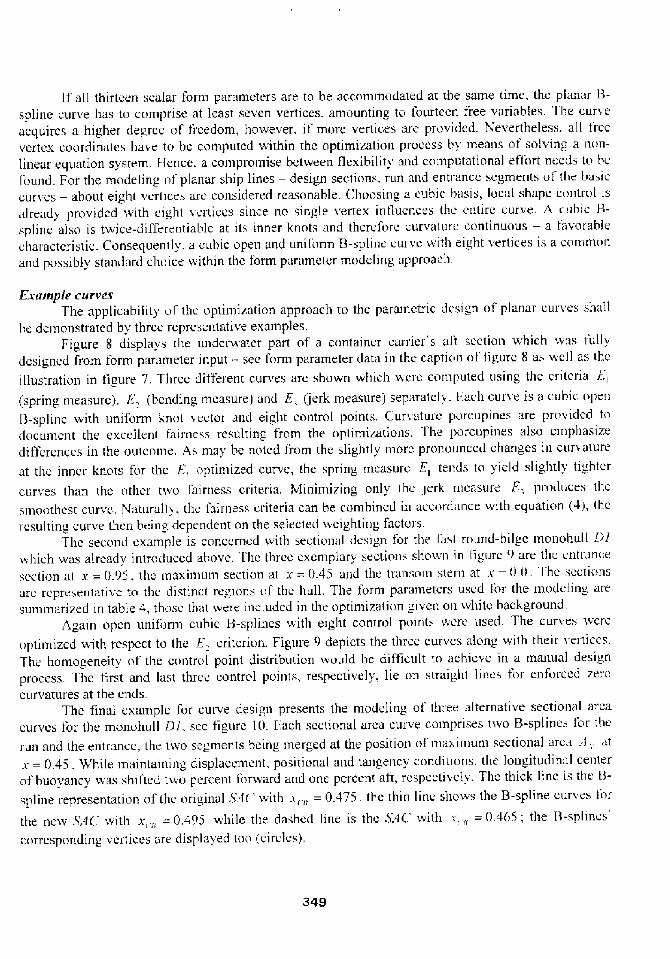
and outcottte depend on a teasonablc initial guess for the vertex coordinat»s to b» contputed, see 'Httrries, I 998! tor an elaborate discussion.
.0 02
0 02
~ i4
Kl
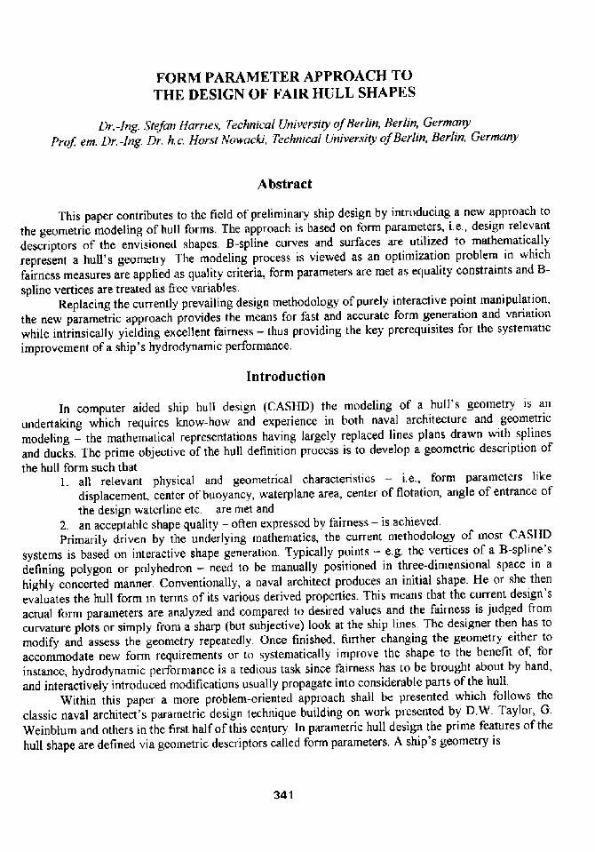
Figure 7. Eorm parameters tor a generic design section�Example att section of a corttaitter carrier
El E2
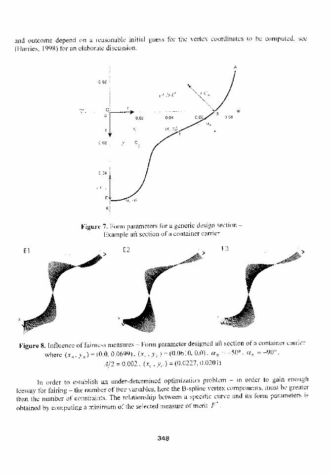
Figure 8. Itttluencc of fairnc»s measures � l ortn parameter designed at't section of a container carrierivherc x�, i �! = �.0, 0. �99!, x,, y, ! = �.06 l 0. 0.0!, rx�-= � s !'. rx,, = � 90
.0/2 = 0.002, x,, p,. ! = !, 27, !.020 l!
In order to cstublislt att uttder-deterrnincd optimization problem � in order to gain «tn>ughlceivay for fairing � the number of lrcc variables, herc the 8-spline vertex compo»e»ts, »tost be gretttcrthan the nutttbcr of cottstraittts. The relationship between;> spccittc cutie and its fornt parameters isobtained by computing a minimum ol'thc selected measure of tncrit f
348
lf all thirteen scalar form parameters are to be acconimodated at tbe same time, thc planar �-spline curve has to comprise «t least seven vertices, amounting to fourteen free variables. The curieacquirc» a higher degree of freedom, however. if morc vertices are provided. Yeverthe!ess. all freevert»x. coordinates have to be computed within the optimization process hy means of solving a n<in-linear equation system, I-Ience. a compromise between flexibility arid coinputationaI effhr needs to bcfound. For the modeling ol planar ship lines � design sections, run and entrance segments of the ba»i»curves � about eight vertices ar»»onsidered reasonable. :hoosing a cubic basis, local »hapc control i»«Iready provided with eight vertices since no single vertex influence th» ciitirc curve. A cubic H-spline also is twice-differentiable at its inner knots and therefor» curvature continuous � a I'avorablecharacteristic. Consequently, a cubic open and unif'orm B-splin» curve ivith eight vertices is a conim<inand possibly standard choice iiithin the form paramelcr modeling ipproach.
Fxample carvesThe applicability ol th» optirniz«tion approach to the parametric design of planar curi es sh«11
hc demonstrated by three representative examples.Figure 8 displays the underwater part of a container carri»r's alt section which iv«s r'ullv
designed from form parameier iriput � »ee form parameter dara iii the caption <if flgure I3 a» v ell as theillustration in figure 7. Tliree ditferent curves are shown which v ere ccmputed using the criteria l;, spring n«easure!, I:, bending measure! and F., jerk measure! separatcli. I.ach curve is a cubic openI3-sp!ine with uniform knot iector and eight control point». Curvatur» porcupines are pr»iidcd todocument the excellent fairness resulting from the optimizations. The porcupines also emphasizedifferences in the outcome, As may be noted from the slightly inore pronounced changes in curiatureat thc inner knots for the l..', optimized curve, thc»pring in»asure F., teiids to yield slightly ti< htcrcurves than the other tivo fairness criteria. Minimizing only the jerk measurer., prodiice» thesmo<ithest curve, IUaturally, the f'airne»s criteria can be combined in a»c»rd«nce with equation �'!, tliciiesulting curve thcii being dependent on the selected weighting, factors.
Thc second example is conc<.mud with sectioii«l desi >n for the last round-bilge monohull L>liihich was already introduced above. flic three cxcniplary sectio»» showii in figurc '! are th<. cntr«ncesection at x = 0,' . thc maxinium secti<in at x = ! 43 and th» tr u>sorn stern at x = !.0. 'I'h» sccti<>nsarc rcpr»sent«tive to the distinct regions of thc hull. The forin parameters u»cd I' or the modeling «resummarized in table 4, th»»c that were included in the optiniization given oii white background.
Again open uniform cubic B-splines with eight control points w»rc used. The curves ivcreoptimized ivith respect to the E. criterion. Figure 9 depicts the three curves along with their i eiciccs.The honiogeneity of the c<introl point distribution would be difficult to achieve in a manual designprocess. The first and last three control points, respectively, lie oii straight lines for enforced zerocurvatures at the ends.
Thc final exainple for curve design presents the modeling of three alternative sectional areacurves lor the rnonohull Dl, see figure 10. E;ach sectional area cuiie coinprises iwo B-spline» I' or therun and the entrance. the tivo segments heing merged at the position»f'maximum sectional area:>, «tx = 0.45. While maintaining displaccmciit, positional and tangency conditions, the longitudin;il ceiiterof buoyancy ivas»hiftcd iivo percent f'orward and one percent aft, resp»»tiiel>. The thick linc is the B-spline representation of the original h4 ivith i,.« � � 0.475, the thin linc shows the B-spline curves I'»rthe neiv &f ". with x, �== 0.49> v bile tlie dashed line is th» XA .' with x, « � � 0.468; the B-splines'corresponding vertices are displayed ton circle»!.
349

'I'able 4. Sets of form paratneters lor ntodelingthe entrance, maximum and aft section of monohull Di
I ntmpn nm t'r 5 'I llt I'frt I I I 0 II'0I-ntr,tnrn I r,ln nn1
I'I rtr Inn .It Irnyn»ltn '
fl l!�5
Ir It!nit;It n'I I
! 0
t,mr nrtt nnsf.,lr �0 tn trr. t Dn k
� If 0'0 I:rt gi' ~ t,m! fn,n Dnd
ln I lllr!n';0 In L11111
nt !nlnrr tn r ntl L
I!nlWDI'I! IIDVD Inrt W.tx15 0 r ! !I 1 I 0
I 1! t 'I rrl' n I I n I n nl
0 l!I! !D'I
I CI--f f
',0
D5
04
03
02
01
CD 0" 01 �: nn .5 � Dr Dtl O' '' - I.iAP FP
Figure l0. Variatiott of !'AC' f' or rnonohull l! ' byshifting the longitudinal center of bt oyancy�1 1igher level tnult.i-segntent B-spline curves
Figure 9. B-spline curves a td their vertices dots!for underwater part of'entrance, maximum and aft
sectio n of' mono hu1 1 D 1
All H-spline curves arc cubic;tnd cotnprise eight vertices. fhe F., criterion was selected as thcsole measure of tnerit. instead ol' optimizing the two B-spline curves of' each .'!'AC' sepa .atcl~, thecurves are combined tn a hi Cher level ntulti-segment curve to be optin»zcd as a whole. Siniilarly, allother basic curves are also treated as multi-segment curves v herc the entrance, straight nirldlc fit'present! and run segtnent are handled in a concerted nanner, see �larries and Abt, 1 !'!'!! for details.
The,h'AC' vari; tion example nicely dcntottstrates that form parameters can be selected andchanged as needed ivithout aff'ecting an> other fornt parameter. within certain lintits form parameterscan be modified and controlled independently Harrics. 1'!QS!.
350

Surface generation
Fair sAinning inrerpolarionWithin the parainetric approach the process ot' designing a vessel is subdivided into three
consecutive steps, thus reducing the complexity of free-form surface design to thc level <if' curveniodeling � see f<gure 3. While in thc first two steps planar curves � ilic hasic curv»s defining thedesired shape and the design sections fiving the ac ual g>eomctry are modeled from 1'orm parametersas discussed above, a surface representation is produced in th» third step bx ineans of a new techiiiquewhich shall be presented below.
An excellent procedure for establishing a inathernatically closed surtacc representation 1'roin anordered set of curves is the skinning> algorithin as introduced by Woodward, 1986 and 1<>88!. ltproduces a 8-spline surfa»c by interpolating a set of transverse curves � thc so-called skin curve!, herca set of q design sections g ii! pararnetrically generated in step , see figure 3. Skinning's basicidea stenis fron1 lofting. 1 owe>, er, th» bl»nding is done with respect to thc control polygons of thc skincurves rather than v ith respect to the skin curves themselves. A new sct <If so-called longitudinal 8-spline curves is gcn»rated sucli that the vertices of the transverse 13-spline curves arc interpolated «tprc-selected parameter values The vertices of the longitudinal curves ar» then employed as thed»fining polyhedron ot a J3-spline surface which contains the skin curves as iso-paraincter lines.
I,et
.Y ii. v! rr Irr � I
/' i<,v! = g < ,v! = PPP�V, i!.A'� < ! li, v!
denote thc 8-spline surface to be coinputed, L'�being its yet unknown»ontrol points. Since the design
s»ctions 0 ii! are to be interpolated h>, F .v!, n r<iws of verti»cs, oider k and the knot vectorused for sectional design are readily chosen for the surface's transverse direction n. For itslongitudinal direction v one m;iy use n columns of vertices, order l and a different knot vector
The interpolating condition readsrrr � I rr � I rrr-I
F u,i ! = Q Q P�h � v ! Y� u! = Q 1;"v',� i ! = ! u'1 �<!!I ! � I I
v hich has to b» fulf<lled;it selected parameter values v, = « ns . z ith d = 0, ..., q � 1. liquation �0!is known as the skinning c<indition. Equating coefficients wc conclude that for each rowi = 0, .... ni � 1 the relation
g P,V, v ! � 1'
must h<ild f<ir all parameter values < with i' � 0..., q � 1. 1hc surface generation problem c;inther»for» b» broken down to determining m longitudinal B-spline curves
rr � Ii., i! � PP A',, v!.
351

eacli witli n unknown vertices P where i = cons ., such hat the q related vertices I' ol all skin
curves are interpolated at i�, i:,, ..., v,, and i... rcspcetiv«ly. The in. n resulting vertices l-'�<>I'all
longitudinal B-spline curve» l., v! then tnakc up th«polyhedron of the skinning surface F u, i ! .Traditional sl'inning algorithms solve the linear equation systems set up from equation I I!
separately for each ' artesian «ompone<>l and row hy row, sce e.u. X<>ivacki. 13loor and !fcksiciv>cz,I <!95!. I>sualfy the parameter values i, at whicti the interpolations sha!I take place are clio»cn tocoincide v,ith the 13-splin«s' kn<>t», i>i this v,ay unf'avorahly prccmptiiig thc surface's longitudinalparamcterization unless thc skin curves happen to bc ordered morc or fcs» «quidistantly.
Alternatively. I'airncss criteria may bc utilized for computing the longitudinal curves i, i ! hyextending the proposed optimization technique for planar curve design to the modeling of »pa««curries. The interpolation pr<>hlcm then becomes: Find a longitudinal 8-»pline curve L, i ! such tli;it;ithree-din>ensional parametri« fairncss critcri<>n is ntinimized, say
~. ,= JI ,',:l' � �'l. ",!'I i �.>!
' r
v hile the � q � 2! ! equality constraintsh, =- x, va!,r, = i!. h, = v, v,! � 3, - !. h =- =, i�! �: =-- 0, �4!
for all u' � 1... �q � 2. are sin>ulf<rn<ousl>< fulfilled at freel>»elected parameter vtilue» i,. I'hcdetermination of thc first vertex <>' = 0! and last vertex <J = q � I! is trivial, since tli««nd I>oint
interpolation propertY can b» put t<> use. I he other vertices P�of all l<>ngitudinal B-spline <l>««««rve»are computed nutnerically I'or each rov, i = <:on~i, just like the vertices of tlie paranietcr desi n«<fplanar B-spline curves, i.c.. by means of optintization,
Despite higher computational effort, this new skinn>ng approach has scv«ral advanta «s over itstraditional counterpart: 'I'hc longitudinal nuinber of vertices n hecoiue» in<lcpcndcnt of the n«rnb«r ot'skin curves q as Ion < as n > q to ensure leeway I'or optirnizati<>n. Th» longitudirial B-spline curvesbeconae inherently fair whi«li has an indirect fairiiig effect on the sl'inning surface; thc appro.ich w;isconsequently called fair ski]>ning. No additional information � for instan«««nd «ondition» � need to h«provided and the longitudinil pararnetcrization of the surface can be chosen;is desired, e.g. «nif'ortu,
ExampIe Surface.sTlie various steps <>I' the skinning interpolation are illustrated In figurc 11, dispfai iiig the
surface generation for thc undcrw;itcr portion of the fast round-hil<'e ni<>n<>hull Ol. I'cn d«sign s««<ion»plus a hov, coiitour were form para<»«ter dcsianed;is cubic 13-»plinc eurYcs, making up the set <>I'sl'incurx es shoxvn in picture I. f-'or e;ich 13-spline curve a unit'orm knot i««tor,>rid «ight vertices were «»ed.'I'hc defining p<>lygons of'.ill skin cut'ics are sh<>wn in pictut«2 Eight h>ngitudinal «uhi«. B-spliiiccurves with uniform knot vectors Yiefc coniputed»uch tllat th« lhr«e-di>nensional F., criterion wa»ininimizcd and the vertices of the ski>i ciirves v ere interpolated, scc picture 3. A total of <5 vertice»v;as clio»en for each longifud>nal curve. the defilling polygotls arc displ;ived irl picture 4. [ he defining<polyhedron of thc resulting hi-cubic 13-spline surf'ace is illustrat«d i>i picture 5. the vcrtice» <>f the 8-spline surface heing the v«r>»amc as those of th» longitudinal <'.«rvcs by premise. Isolin«s <>t' tflcresulting B-spline»urface arc present«d in f>gure 12,
352

4
5
Figurc 11. Steps ot the lair skinning interpolation Figure 12. Perspective. side and top views ol the� Design sections and bow contour for underwater skinning 8-spline surlacc for underv ater part ot
part of monohull 0/ monohul 1 Ol
Figure 13. Comparison oi 1'ully form parameter designed monohulls � Vlonohull Ol initial! andautomatically derived vessel varied! with decreased was e resistance
1 igure 2 depicts the final form parameter generated surfaces for both the und«rwater part andthe freeboard of Dl. The follov ing basic curves were used for this design task: 5'A .', D!Vi.. 'T' .',DF ,', TAJ3 at the design water!inc and Thf.' at the center plane curve, see again tables ] anrt 2. Bodyplans of two alternatii c vessels arc suhniitted in ftgure 13. the sections heing derived from intersecting,the surfaces with planes x,, =- const,
It shall bc pointed out that absolutely no manual vertex manipulations >vere performed: ratherall shapes werc purely derived from t'orm parameter input, Given quantitics like displacement, centerof buoyancy, v aterplane area and center of flotation werc rtiet with an accuracy of around 0.1 in. '1 hc
353

modeling examples required only a few C.'PU-seconds on a curt»«i I'C' with a 300 MIIz 1'ciitiumprocessor for the an entire liull and considerably less for a singl» cur~e. Addition;il examples ni;iy befound in Harrics and Abt, 1997!, Harrics, I'!98! and Harries rued Abt. 1999!, the former tiii> beingmore elaborate with regard to ship design problems, the latter focusing <>o sailing yachts.
Design scenarios
Geometric modelingParametric curve and surface design requires that values lor form paramctcrs b» knoiiii. In
general a naval architect m;iy not be able to immediately spccit'i all form parameters ncctlcd t<»i>odclan entire hull geometry frortt scratch. liow:ver. thc introduced r»«them«tical model permits t >at anifornt parameters beyond a small set nf necessary mainly positional! parameters may bc lef't n> bcdetermined from the optimization if unknown «t the beginiiing. They can then be nu>dificd andreintroduced into the i>ptimization so as to gradually build up the final shape.
Frequently a design task starts lrom an available parent hull. In this case thc cxistini> i esse! «; inbc analyzed for its forin parameter content and subsequently redesigncd iiithout any difficulties a» hasbeen done for the example monoltuII i! l. Systematically varying the geometry then beconies a matteroI simply and intuitively changing the values of selected parameters.
r4pproach to formal itydrod! namic optimization'fhis also opens the path to the second and optional! design sc»nario ot forinal hydri>din;ii«ic
optimization. In the proposed pararnctric design method a bull s gcomciri is created from its <lie»etgeometric properties, deterniining the vessel's hydrostatic conditions, I'lic g»i>crated shapes accui;itclymeet all spccitied form parameters «nd intrinsically acquit»»xccllcnt f'iirnes». Both t'eatures arc keiprercquisites for the systematic optimization of a hull's most import«i>t indirect properties � i.c., itsvarious hydrod!namic qualities like resistance, propulsion and sea-kecping � and. conscqucntli, ihcparametric method is well-suited for integration into a synthesis mndel of formal hydn>dynami».optimization.
The synthesis model for hydri>dynamic design as presented bi Harrics. 19'!8! coiit,iii>s fourstages;
Form generation via paramctnc design.2. Fluid dynamic analysis by means of numerical floiv simulatinn.
Design evaluation � for instance in terms of v'ave resistance,4. Systematic variation driven by non-linear programming.I he optimization process contlnerl«es with an initial set ol free form p iramctcrs, i,»., the free
variables of the hydrodynamic design problem. This set ot form paramct»rs is used as input to ]he firststage � shape design in v hich the hull is pararnctrically gener itcd within an inner optimization loopas discussed throughout this paper. The hull geometry is then passed on to the second stage � shapeanalysis in v hich th» flow tield is computed using a state of the art C'omputational Fluid Dynamics CFD! code. At the third stage � shape evaluation � the performance ot The current hulI is dctcrmined.yielding a hyclrodynamic inc«sure oI rncrii by which to assess the geotnctry, At the t'ourth stage�shape variation � the nteasure of nterit is exainined to decide on a proinising «hange t>f Ihc freevariables according to th» chosen optimization strategy. In I-Iarries. 1998'! a multidintensionalconjugate gradient method is used in coir>binatiori v ith a CJoldcn Se«tioii line search. Neiv ialucs forthe frcc form parameter are thus devised and then transferred to th» geoinetric ntodcling process. Thenext round of the hydrodynamic optimization loop is started. In I.he cnd, a local optimum is found andthe process is terininatcd.
354

Following this procedure an example wave resistance minimization was perforined lor thc fastntonohull Dl at its design speed F�= i!,433, see Harries, 1998! for a comprehensive discussion. '1 hcwave resistance vvas computed with the non-linear potential t!ow code of the CI'D system SHII'FLOWby Larsson et al., ]990! after a careful reliability study had revealed good accuracy ol' rankingalternative hulls of the D-Series correctly Harries and Schulze, 1997!. ln figure 13 the body plans <>tthe initial design and a variation developed within the forrnal optimizatioii are shown. The geometricchanges deduced automatically display meaningful features like bulbous shapes close to the forwardperpendicular, decreased angle of entrance of the design waterline and increased breadth of ihctransom. The displacement and the waterplane area were kept constant during the optiinization bymeans of simply freezing these important form parameters. promising reductions in resistance could beachieved. Compared to the initial hull the varied design given in figure 13 1'or instance encounters 7",~oless wave resistance and 4.5"fo less total resistance at I;, = 0.433.
Naturally, the acconiplished iniprovements can only be as reliable as the computational niodclemployed io analyze the flow field. One should therefore not expect the full advantage predicted andexperimental validation studies are still required to prove the validity of C'.FD-based hydrodynaniicoptiniization.
Conclusion
A iiew approach to the parametric design of ship hull forms has been presented. The shape ofthe envisioned hull is specifie in terms of its desired form parameters from which basic curves arelaid out. The basic curves then contain all information needed to derive a design section at anylongitudinal position. An ordered set of design sections is created and then interpolated to produce anaccurate and mathematically closed surface description.
Coinpared to previous methods major iniprovements are:l. A 13-splincs curve representation is utilized which provides high flexibility and alkiws flor
the accommodation of an> desired number and meaningful combination ot tormparaiueters.
2. Fairness criteria are applied at thc carly stage of shape definition rather than at the laterstage of shape evaluation.
3. All important planar curves � the longitudinal basic curves and the representative designsections � are modeled in a unified way via optimization.
4. 'I he common set of' basic curves is extended by several more longitudinal curves whiclimay bc included depending on the modeling problein.
5. A new skinning interpolation for the generation of 8-spline surfaces is introduced whiclialso eniploys fairness from a functional point of view.
6, '1 he entire process of hull shape generation is supported by forni parameters without ihcneed for a designer s interaction, e.g. manual point control,
7. The approach is thus well applicable to fully automatic hydrodynatr>ic optimization.Ncverthdess, further research is required to develop the form parameter approach to its full
potential, J<egarding curve optimization for instance inequality constraints should bc taken int >account � e.g. to confine dcsigii sections to lic inside the hull's maximum pcrrnissible draft and beamand outside given hard points which may originate for example front prcdctcrntincd containerpositions or structural considerations. Vforcover, the parametric methods mi>st be extended to complexhull forms which also feature bulbous bows, stern bulbs etc. These substantial design elenienis haveyct to bc suitably paramctcrizcd and adequately integrated.
355

References
I"ullcr, A.L. and Aughey, M.F:. �977!, "Coinputcr Aided Ship Hull Definition at the NavalShip Engineering Center', .4'p'mpo»iunt for Ctnnpttt<'r-rf t<le<l Hul! Surfttc< l>ejinitiort, Annapolis.MD, USA.Hurries, 'S. �998!, "I'arametric Design anti Flydrod! namic !ptiniization of' Ship llull I'<irms'.Ph.o. Thesis, lnstitut lur Schiffs-und Meerestechnik, '1'e< hni sche t 'nt»er»itiit Berlin, ier<ita<1!",published at Mensch k Buch Verlag, Berlin, 1998.Ilarrics, S, and Abt, C. �999!, 'Parametric Design aiid Opiiinization of Sailing '<'acht»',Proceeding» of the s'iVAMEChc»apeake Sailing !'atht Sytnpo»iuni. Annapolis. MD, I iSA.Harrics, S. and Abt, C. ] 9'�!, "Paran>etric Curve Design applying Fairite»s Criteria',lnternati<inal Ifrorkslu<P on Ci eating F<tir un<1 Shape-Pr<'»ervini.' 'ttr»<'»and Surface<. IvctworkFair»hape, Berlin/Pot»dam. germany; published at Tcubner, 19'!8.IIarries. S. and Schulzc, D, �997!. "Nunterical Investigation ol a S! stcinatic Model Scrie» forthe Design ol Fast Monohulls", FALSI'9 - -tth international Conf<!r<nt< e on i.'«it,h'e<sTranspot talion, Vol. I, Sydney. Australia.Jacobscn. A, and Kracht, A.M. �992!, ' D-'Series, Systeniatic Evperiments vvith Models of'I'astTwin-Screw Displacement Shi ps",,5'<Yrf ME Vol, 100.Kwik, K..H. Ic�9!, "Zur Mathematischen Darstellung von Schiffslinien On the Mathematic;tlRepresentation of Ship I.ines!", in ierman!, Sehifj<'technik, Band 16, I lcf't 83.Larsson, L.; Broberg, L�Kim, K.-J, and Zhang, D.H. �990!, "A Method for Resist;incc andFlow Prediction in Ship Design", SPUME Transaction», Vol. 98,Munchmcyer, I.C.; Schubert. C. <and Nowacki, H. �97'!!. "Interactive Design of I air ! lullSurfaces using 13-splincs", C'ontlruter,41rpli<'ation» iii the At<ton<ation <ij Shili!:artf !lier«tirntand.4'hip Oe»i!<n ill, IFIP, North-Holland I'ublishin < Con<patt!.Nowacki, H,; Creuti, Ci. and Munchmcycr, F.C. �977!. "Ship l.ines Creation by :omputcrObjectives. M<:thod», and Results", .iJ'nipo»ium on t"ompttt<o'-~li<letl Hull .5'urfa<:e D<. j<ntt<otuAnnapolis, MD. I IS A,Nowacki. FI.; 1 iu, I!. and Lii, X. �990!, 'I'airing Bezicr curves with constraints", C«utliuter:Ii<letl geometric Oe»ign 7, North-Holland.Nowacki, I I.; 13loor. M,I,Ci. and Oleksiev icz, B. L'ds.! �995'I, 'Computational <eomctr! f<irShips". world 92'<ientifi<:, London.Press, W.H.; et al. �992!, 'Ntimcrical Recipes in C - 'I he Art ol Scientific Computin ". 2ndedition, Cambridge hiiversit> Press.Reed. A.M. and No»vacki, I I. �974!, "Inieractive Creati<in of Fair Ship Lines"..Jot<rn<tl <ij ShipRe»ear <.'h. Vol. 18. No. 2.Rogers. D,I'. and Adorns, J A. �990!. "Mathematical I fcntents for Computer iraphics". 2<i<iedition, Mc 'rani'-Hi ll, Nevv E'or k.'A'oodv ard, C.D. < 1986!, -Methods for Cross-Sectional Design of I3-spline Siirfaces .F URO rlUP111 .'S'<86, North-I lolland Publ., Amsterdam.'<Voodward, C.D. �988!, "Skinning techniques for interactive B-spline surface interpolation', '<nnput< r-. Iitl< «'De»i< n, Vol<une 20, No. 8.
6i.
9,
10.
12
13.
16.
17.
356
It is the authors firm believe that the f<irm parameter approach i<i the design of fair huff »hapcswill play an important role in establishing a modern hull design nicthodology to the benefit <>f I'asterpreliminary an better hydrodynamic design,