Parts Assembly by Throwing Manipulation with a One-Joint...
6
Parts Assembly by Throwing Manipulation with a One-Joint Arm Hideyuki Miyashita, Tasuku Yamawaki and Masahito Yashima Abstract— The present paper proposes the learning control method for the throwing manipulation which can control not only the position but also the orientation of the polygonal object more accurately and robustly by low-degree-of-freedom robotic arm. We show experimentally the validity of the proposed control method with the one-degree-freedom robotic arm. We also demonstrate the usefulness of the throwing manipulation by applying it to sorting task and assembly task on experiments. I. INTRODUCTION In the present logistics systems or automated assembly lines, many conveyors and vehicles are used for transporting packages or parts, which make the speed of the physical distribution and the production flow be slow and the plant and equipment costs be high. Transportation by throwing objects can produce the following advantages: (1) mechanical equipments are simplified or less required; (2) flexibility of the systems is enhanced; and (3) the transportation processes are speeded up [3]. We consider the applications of the throwing manipulation to transporting, orienting, sorting and assembling various types of objects. Fig. 1 shows one of the application examples, in which a one joint robotic arm throws objects with various orientation carried by a belt-conveyer and sorts them with appropriate orientation in a storage pallet with an array of nests, each nest holding a single object. The objects in the storage pallet will be then stored in a warehouse or will be grasped by a robot gripper in assembly lines. Instead of a manipulation of an object with grasp, the throwing manipulation has drown attention recently in the field of robotics [1], [7], [8], [9], [10]. This is because the throwing manipulation cannot only manipulate the object outside the movable range of the robot, but also manipulate the position and orientation of the object arbitrarily by a robotic arm with fewer control inputs. Lynch et al [5], [6] present the motion planning for the dynamic manipulation such as throwing an object and propose the open-loop controller based on nonlinear opti- mization techniques. However, they do not aim at throwing the object accurately and robustly. The experimental results show that the controller is subject to the modeling error and sensing error. Aboaf [2] applies a learning control method to the throwing of a point mass object to overcome these problems. However, constraints on dynamical robot system and actuator’s performance limits, etc are not considered to find control inputs. The authors [7] propose the control method for throwing point mass object accurately, which The authors are with Dept. of Mechanical Systems Engineering, National Defense Academy of Japan, 1-10-20, Hashirimizu, Yokosuka, JAPAN {g47091, yamawaki, yashima}@nda.ac.jp Storage pallet Object Throwing Arm Fig. 1. Application of the throwing manipulation combines the learning control techniques and the nonlinear optimization techniques. As far as I know, there has been no work which takes into consideration the orienting a polygonal object accurately by a throwing manipulation, which is very important in the case of sorting and assembling various types of objects, as shown in Fig. 1. The present paper proposes a learning control method for the throwing manipulation which can control not only the position but also the orientation of the polygonal object more accurately and robustly to uncertainties. We show experimentally the validity of the proposed control method and the feasibility of assembly process by the throwing manipulation. The paper is organized as follows: In Section III we study the dynamical constraint on the throwing manipulation. Section IV presents the motion planning by optimization, and Section V proposes the learning control method. Finally, Section VI presents experiments with a one-degree-freedom robotic arm. II. NOTATION AND ASSUMPTIONS We consider a throwing manipulation of a polygonal rigid- object by the rotational one-degree-of-freedom robotic arm in the vertical plane, as shown in Fig. 2. A reference frame x-y is fixed at the pivot point of the robotic arm. The gravitational acceleration −g< 0 acts in the −y direction. The position and orientation of the object in the x-y frame is described as (x, y, φ). The angle of the arm is θ, which is set to 0 deg when the arm is horizontal. The top surface of the arm intersects with the pivot point. The arm throws the object by counterclockwise rotation. It is assumed that the thrown object is captured by a storage pallet fixed at a goal without slipping, rolling or rebounding in order to simplify the analysis. A frame u-v is located on the center of mass of the object, where the +v direction is opposite to gravity when the arm angle is θ =0. The moment of inertia of the object and its The 2010 IEEE/RSJ International Conference on Intelligent Robots and Systems October 18-22, 2010, Taipei, Taiwan 978-1-4244-6676-4/10/$25.00 ©2010 IEEE 43
Transcript of Parts Assembly by Throwing Manipulation with a One-Joint...
Parts Assembly by Throwing Manipulation with a One-Joint Arm
Hideyuki Miyashita, Tasuku Yamawaki and Masahito Yashima
Abstract— The present paper proposes the learning controlmethod for the throwing manipulation which can control notonly the position but also the orientation of the polygonal objectmore accurately and robustly by low-degree-of-freedom roboticarm. We show experimentally the validity of the proposedcontrol method with the one-degree-freedom robotic arm. Wealso demonstrate the usefulness of the throwing manipulationby applying it to sorting task and assembly task on experiments.
I. INTRODUCTION
In the present logistics systems or automated assemblylines, many conveyors and vehicles are used for transportingpackages or parts, which make the speed of the physicaldistribution and the production flow be slow and the plantand equipment costs be high. Transportation by throwingobjects can produce the following advantages: (1) mechanicalequipments are simplified or less required; (2) flexibility ofthe systems is enhanced; and (3) the transportation processesare speeded up [3]. We consider the applications of thethrowing manipulation to transporting, orienting, sorting andassembling various types of objects.
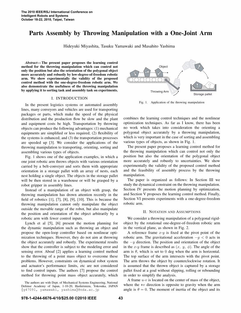
Fig. 1 shows one of the application examples, in which aone joint robotic arm throws objects with various orientationcarried by a belt-conveyer and sorts them with appropriateorientation in a storage pallet with an array of nests, eachnest holding a single object. The objects in the storage palletwill be then stored in a warehouse or will be grasped by arobot gripper in assembly lines.
Instead of a manipulation of an object with grasp, thethrowing manipulation has drown attention recently in thefield of robotics [1], [7], [8], [9], [10]. This is because thethrowing manipulation cannot only manipulate the objectoutside the movable range of the robot, but also manipulatethe position and orientation of the object arbitrarily by arobotic arm with fewer control inputs.
Lynch et al [5], [6] present the motion planning forthe dynamic manipulation such as throwing an object andpropose the open-loop controller based on nonlinear opti-mization techniques. However, they do not aim at throwingthe object accurately and robustly. The experimental resultsshow that the controller is subject to the modeling error andsensing error. Aboaf [2] applies a learning control methodto the throwing of a point mass object to overcome theseproblems. However, constraints on dynamical robot systemand actuator’s performance limits, etc are not consideredto find control inputs. The authors [7] propose the controlmethod for throwing point mass object accurately, which
The authors are with Dept. of Mechanical Systems Engineering, NationalDefense Academy of Japan, 1-10-20, Hashirimizu, Yokosuka, JAPAN{g47091, yamawaki, yashima}@nda.ac.jp
Storage pallet
Object
Throwing Arm
Fig. 1. Application of the throwing manipulation
combines the learning control techniques and the nonlinearoptimization techniques. As far as I know, there has beenno work which takes into consideration the orienting apolygonal object accurately by a throwing manipulation,which is very important in the case of sorting and assemblingvarious types of objects, as shown in Fig. 1.
The present paper proposes a learning control method forthe throwing manipulation which can control not only theposition but also the orientation of the polygonal objectmore accurately and robustly to uncertainties. We showexperimentally the validity of the proposed control methodand the feasibility of assembly process by the throwingmanipulation.
The paper is organized as follows: In Section III westudy the dynamical constraint on the throwing manipulation.Section IV presents the motion planning by optimization,and Section V proposes the learning control method. Finally,Section VI presents experiments with a one-degree-freedomrobotic arm.
II. NOTATION AND ASSUMPTIONS
We consider a throwing manipulation of a polygonal rigid-object by the rotational one-degree-of-freedom robotic armin the vertical plane, as shown in Fig. 2.
A reference frame x-y is fixed at the pivot point of therobotic arm. The gravitational acceleration −g < 0 acts inthe −y direction. The position and orientation of the objectin the x-y frame is described as (x, y, φ). The angle of thearm is θ, which is set to 0 deg when the arm is horizontal.The top surface of the arm intersects with the pivot point.The arm throws the object by counterclockwise rotation. Itis assumed that the thrown object is captured by a storagepallet fixed at a goal without slipping, rolling or reboundingin order to simplify the analysis.
A frame u-v is located on the center of mass of the object,where the +v direction is opposite to gravity when the armangle is θ = 0. The moment of inertia of the object and its
The 2010 IEEE/RSJ International Conference on Intelligent Robots and Systems October 18-22, 2010, Taipei, Taiwan
978-1-4244-6676-4/10/$25.00 ©2010 IEEE 43

r
l
x
y
d
u
v
lAlB
A
B
θ
MAN
MB
g
Fig. 2. Notation for throwing manipulation
mass are J and m, respectively. The polygonal object makesline contact with the arm surface, and the vertices of thecontacting edge are A and B. The distance in the directionof u between the object center of mass and the vertices Aand B are lA and lB , respectively. The height of the centerof mass from the arm surface is d. The distance between theobject center of mass and the pivot point is l. When the armis horizontal, the x location of the object center of mass inthe reference frame is r.
The stoppers with a sharp edge are rigidly attached to thetop surface of the arm to stop the object from sliding on thesurface. We assume that there are no friction between theobject and the stoppers.
III. THROWING MANIPULATION
The motion of a throwing manipulation is divided broadlyinto two phases before and after an object’s release.
A. Motion before Object’s Release
The motion of the object relative to the arm is constrainedin order not to slip, roll or break contacts before the object’srelease. The motion of the arm is also constrained by thejoint actuator performance.
1) Object Constraints: Since the object does not slide onthe arm surface by the stoppers, we consider only the verticalmotion with respect to the arm surface and the rolling motionabout the vertices A and B.
The normal reaction force N acting on the object can bedescribed as
N = mrθ − mdθ2 + mgcθ (1)
The reaction moment MA and MB from the arm abouteach vertex A and B can be described as, respectively,
MA = Jθ − mlArθ + md2θ
+ mlAdθ2 + mdrθ2 − mlAgcθ − mdgsθ (2)
MB = Jθ + mlBrθ + md2θ
− mlBdθ2 + mdrθ2 + mlBgcθ − mdgsθ (3)
where sθ = sin θ and cθ = cos θ.To achieve the stable throwing, the robotic arm has to
accelerate such that there is no relative motion between the
object and the arm before the object’s release, which iscalled the dynamic grasp. We take into account the followingconstraints to achieve the dynamic grasp.
(i) Contact Constraints; which make the object maintainthe contact with the surface of the arm.
N(t) > 0 (4)
(ii) Un-rolling Constraints; which prevent the object fromrolling about the vertices A and B.
MA(t) < 0 (5)MB(t) > 0 (6)
2) Arm Constraints: The arm is subject to the constraintson the actuator performance and the robot mechanism.
(i) Joint Angle Constraints
θmin < θ(t) < θmax (7)
To release the object in the right half space, we setθmax = π/2 and θmin = −π/2, respectively.
(ii) Actuator’s Torque-Velocity Limits
θmin < θ(t) < θmax (8)τmin < τ(t) < τmax (9)
τmax = ξ(θmax) (10)
where (10) shows the relationship between the max-imum torque and maximum velocity of an actuator,which is determined by the actuator’s operation range.
B. Motion after Object’s Release
After the object’s release, the object’s motion duringa free-flight is determined by the arm’s state (θt, θt), athrowing radius lt at a release point and a flight time tf .
Since we have four variables (θt, θt, lt, tf ) as parametersin the throwing manipulation, the one-joint robotic arm cancontrol four object’s state variables in a six-dimensionalplanar state space (x, y, φ, x, y, φ) through one throwing.
In this paper, in addition to the object’s position andorientation (x, y, φ), we choose the vertical velocity y ata goal as the controlled object’s variables. By specifyingan appropriate velocity y, we can find object paths withvarious loci which reach to the same object’s position andorientation, which helps to plan the object’s path so as toavoid obstacles in front of the goal. We can also adjust animpact velocity at landing. The condition for the velocity atthe goal expands the feasibility of various throwing tasks.
We define the object’s state variables in a flight time tf ,which can be controlled by the one-joint robotic arm, as
z = [ x(tf ), y(tf ), φ(tf ), y(tf ) ]T = g(u) ∈ �4, (11)
which can be expressed by free-flight ballistic equationsusing parameters u = [ θt, θt, lt, tf ]T ∈�4.
The object’s four state variables z is uniquely de-termined by specifying the four-dimensional parameters(θt, θt, lt, tf ), and vice versa. If we move the robotic armso as to achieve the arm’s state (θt, θt) at a release point,
44
then the object on the arm surface at a throwing radius lt canbe thrown to a desired state z in a time tf after the object’srelease. In the next section, we present the motion planningof the robotic arm.
IV. MOTION PLANNING
For a given initial state of the object and the roboticarm, the motion planning problem is to find a robotic arm’strajectory to throw the object to the goal state under theconstraints on the dynamic grasping and robotic arm motion.
A. Joint Trajectory Parameterization with B-splines
We use uniform cubic B-splines to represent the jointtrajectory since the continuity of the trajectory betweenadjacent B-spline segments is guaranteed [4].
The motion time interval [0, tt] from the start of the arm’smotion until just before the object’s release is divided into nknots with evenly spaced in time, ∆t, such as t0(=0) < t1 <· · · < tn(= tt). The joint trajectory θi(t) (i = 0, 1, · · · , n)on each interval [ti, ti+1] is expressed by
θi(s) =i+2∑
j=i−1
θjBj(s) (12)
where t(s) = ti + s∆t, (0≤ s≤ 1), and θj and Bj(s) arethe control points and basis functions of the uniform cubicB-spline. The final joint angle is equivalent to the throwingangle such as θn = θt.
The release time tt (= tn =n∆t) can be freely chosen. Fora given n, ∆t is free. Since the cubic B-splines lie withinthe convex hull formed by the control points θj , the jointtrajectory (12) passes near the control points. To obtain anoptimal arm trajectory, we optimize the control points
θ = [ θ−1, θ0, · · · , θn+1 ]T ∈ �n+3 (13)
and the time ∆t (< ∆tmax) including some of the joint’sinitial and final states by formulating the motion planningproblem as a constrained optimization programming prob-lem. We show the constraints and objective function of theoptimization programming problem below.
B. Finite-dimensional ConstraintsTo prevent the robotic arm from violating the constraints
on the dynamic grasping due to unknown disturbances whichare not shown in the nominal model and from saturatingcontrol inputs, we find the joint trajectories which satisfyconstraints (4)∼(9) with sufficient tolerance. We introducemargin variables ∆N, ∆MA, ∆MB, ∆θ, ∆θ, ∆τ into eachconstraints, respectively, and maximize the magnitudes of themargin variables in the optimization problem.
We rewrite the dynamic grasping constraints (4)∼(6) byusing margin variables ∆N, ∆MB > 0, ∆MA < 0. Inaddition, substituting (12) into them yields finite-dimensionalconstraints sampled at the knot points t0, · · · , tn as
N(θi,θi,θi
)> ∆N, i = 0, · · · , n (14)
MA
(θi,θi,θi
)< ∆MA, i = 0, · · · , n (15)
MB
(θi,θi,θi
)> ∆MB, i = 0, · · · , n (16)
Similarly, the arm’s motion constraints (7)∼(9) can beconverted into finite-dimensional constraints by using marginvariables ∆θ, ∆θ, ∆τ > 0 as follows:
θmin+∆θ < θi < θmax−∆θ, i=0, · · · , n (17)
θmin+∆θ < θi < θmax−∆θ, i=0, · · · , n (18)
τmin+∆τ <τ(θi,θi,θi
)<τmax−∆τ, i=0, · · · , n (19)
where the joint torque τ is expressed by the motion equationof the robotic arm, which is
τ(θi,θi,θi
)= JR(θi)θi + h(θi, θi) (20)
where JR is the inertia matrix and h represents the gravity,friction force and reaction force from the object.
C. Objective Function
Since the throwing manipulation is generally dynamic andfast and needs larger joint driving torques, it is easy forthe object to roll on the surface of the arm or to breakcontacts with the arm during the manipulation by violatingthe dynamic grasp constraints. We are greatly concerned withmaking the throwing manipulation more robust and stable todisturbances and trajectory errors, etc.
In order that the constraints on the dynamic grasping andthe arm’s motion can be satisfied with sufficient tolerance,we maximize the margin variables
d =[∆N ∆MA ∆MB ∆θ ∆θ ∆τ
]T ∈ �6 (21)
in the optimization problem shown below.
D. Optimization Programming Problem
For a given object’s goal state zd, we find an optimal armtrajectory by solving the following optimization problem.
max :12dT Wd (22)
subj. to: zd = g(u) (23)c ≤ 0 (24)
θ0 = 0 (25)
find: θ and ∆t
Eq. (22) is the objective function to maximize the marginvariables, where W is a weight matrix. The free-flightmodel is used as the equality constraint (23). The inequalityconstraints shown in Section. IV-B are combined as shownin (24). As boundary conditions, the initial angular velocityis specified by (25). In contrast, the initial angle and thefinal angle and velocity are derived from this optimization.We use sequential quadratic programming (SQP) to solvethe nonlinear programming. Once we find the arm trajectoryparameters (θ, ∆t), we can calculate the joint trajectoryusing (12).
45

-0.2 -0.1 0 0.1 0.2 0.3 0.4 0.5
-0.2
-0.1
0
0.1
0.2
0.3
0.4
x [m]
y [
m]
Goal
Fig. 3. Throwing manipulation found by the optimization.
0 0.1 0.2
0
0 0.1 0.20
5
10
θ [r
ad/s
]
0 0.1 0.2-300
-150
0
150
θ [r
ad/s
2]
θ [r
ad]
-π/4
-π/8
π/8
θt = 0.346 radθt = 9.28 rad/s
Time [sec]Time [sec] Time [sec]
θo = -0.596 rad tt = 0.199 sec
Fig. 4. Arm trajectories found by the optimization.
E. Simulation Results
Consider a throwing manipulation of a rectangular objectto a goal. The parameter values of the object and robotic armare described in Section VI. The optimization programmingproblem is formulated with n = 10. Since a local optimumfound by SQP depends on the initial guess, SQP is solvedwith many different initial guesses given at random.
Fig. 3 shows the simulation result found by the opti-mization which represents the motions of the object androbotic arm. The object is thrown to the goal (x, y, φ) =(0 m, 0.4 m, 150 deg) with the velocity y = 0. We assumethat the object lands at the storage pallet located at the goalwithout slipping and rebounding to simplify the analysis.
Fig. 4 shows the corresponding arm trajectories, whichhave the initial state (θ0, θ0) = (−0.596 rad, 0 rad/s) andfinal state (θt, θt) = (0.346 rad, 9.28 rad/s) at a release timett =0.199 s, respectively. The arm is maximally deceleratedat the release time to set the object free instantaneously.After the release time, the robot arm is moved with the jointacceleration at the release time until the arm stops, which isnot described in Fig. 4.
Fig. 5 shows the arm trajectories obtained for differentinitial guesses. The arm trajectory in Fig. 4, which has themaximum value of the objective function, is chosen amongthem.
V. LEARNING CONTROL
If we have an exact throwing model, then we can obtainan optimal arm trajectory to throw an object to the goalby using the motion planning method discussed in the
0 0.1 0.2 0.3 0.4 0.5 0.6 0.7 0.8 0.9 1-1
-0.5
0
0.5
1
[rad]
Time [sec]
θ
Selected trajectory
Fig. 5. Arm trajectories found for different initial guesses, where ∆tmax =100 msec.
previous section. To model the throwing manipulation systemaccurately, we are required not only to implement parameteridentification whenever the change of the object, but also toconsider the dynamics of the interaction between the robotand the object, as well as the correction of the vision sensoretc. In general, it is impossible to obtain exact models.
In the present paper, instead of raising accuracy of anapproximate model itself, we overcome the problems of themodel with errors by applying an iterative learning controlmethod to the throwing manipulation.
A. Introduction of Virtual Goal
To find an optimal arm trajectory, instead of setting anobject’s goal state zd for the optimization programmingproblem, we introduce a virtual goal state zd, which isupdated at each throwing trial in order that the robotic armcan throw the object to the goal state zd as closely aspossible. The basic idea of the learning control using thevirtual goal is shown in [2].
The virtual goal is obtained as follows. The error betweenthe goal state zd and the actual state z is given by
ej = zd − zj (26)
where j denotes the trial number.According to the value of the error, the virtual goal zj+1
d
of the j+1th throwing is updated as
zj+1d = zj
d + Kei (27)
where the diagonal matrix K is gain parameters.Replacing the goal state zd in the left-hand side of (23)
with the virtual goal state zd, we find an optimal arm tra-jectory by solving iteratively the optimization programmingproblem (22)-(25) at each throwing trial.
B. Learning Control Algorithm
The algorithm of the learning control is shown below.1) The optimization programming problem is solved to
obtain the arm trajectory for the first throwing (j = 1).In the same manner described in step 5 and 6, we makethe robotic arm throw the object and measure the actualobject state z1 with a camera.
2) We calculate the error ej of the j th throwing by using(26). If the error norm is greater than the value of thethreshold, we move to the next step. Otherwise we
46

assume that the arm succeeds in throwing the objectto the goal, and the learning control is terminated.
3) The virtual goal zj+1d is updated by using (27).
4) The optimization programming problem is solved toobtain the arm trajectory for the j+1 th throwing.
5) To throw the object, the robotic arm is controlledwith a PD-compensator so that the arm can track thetrajectory obtained in step 4.
6) We measure several positions and orientations of theflying object with the camera and estimate the object’sballistic trajectory through the least square approxima-tions. We obtain the actual object state zj+1 from theestimated trajectory and return to step 2.
VI. EXPERIMENT
A. Throwing Robot System
We have developed the throwing robot system which canperform the throwing in the vertical plane as shown inFig.6. The aluminum arm is centrally-mounted and 62 cmlong and 15 cm wide plate. The arm is controlled with PDcompensators and is driven by the AC motor with a harmonicdrive gear, which has the maximum torque τmax =18 Nm andthe maximum speed θmax = 4π rad/s. The throwing radiuscan be changed by adjusting the position of a thin plate onthe arm surface. The object on the plate is constrained with2 mm high stoppers so as not to slide on the arm surface.
We use a rectangular parallelepiped wooden block as theobject whose mass and size are 29 g and 6 cm×3 cm×3 cm,respectively. The moment of inertia of the wooden block isestimated on the assumption that the block is homogenousand symmetrical. We measure the positions of markers puton the object during the flight with a camera at a rate of1 kHz to estimate the object trajectory. The concave storagepallet of wood is fixed at a goal in the vertical plane.
B. Experimental Results
The goal state zd is set to (0 m, 0.4 m, 150 deg, 0 m/s).Fig. 7 shows the transitions of the error norms of the position,orientation and vertical velocity at the goal. The value of theerror norm is reduced gradually by repeating the learning.The error norm of the 10th throwing is less than 2.5 mm, 0.1deg and 0.01 m/s, respectively. These experimental resultsshow that the proposed method enables the robotic arm tothrow the object to the goal accurately. Fig.8 shows the
Storage pallet
Arm
Motor
Object
Fig. 6. Throwing robot system
1 2 3 4 5 6 7 8 9 100
0.01
0.02
0.03
1 2 3 4 5 6 7 8 9 100
0.03
0.06
1 2 3 4 5 6 7 8 9 100
0.04
0.08
Trial number i
Po
sitio
n e
rro
r
[m
]
Orie
nta
tio
n e
rro
r
[ra
d]
Ve
locity e
rro
r
[m
/s]
Fig. 7. Transitions of error norm of object’s state at the goal
0 0.02 0.04 0.06 0.08 0.1 0.12 0.14 0.16 0.18 0.2 0.22
0
π/4
θ [r
ad
]
0 0.02 0.04 0.06 0.08 0.1 0.12 0.14 0.16 0.18 0.2 0.220
2
4
6
8
10
π/8
-π/8
-π/4
θ [r
ad/s
]
Time [s]
i=10 (final trial)
i=10 (final trial)
i=1 (1st trial)
i=1 (1st trial)
Fig. 8. Arm trajectories found by the optimization at each trial
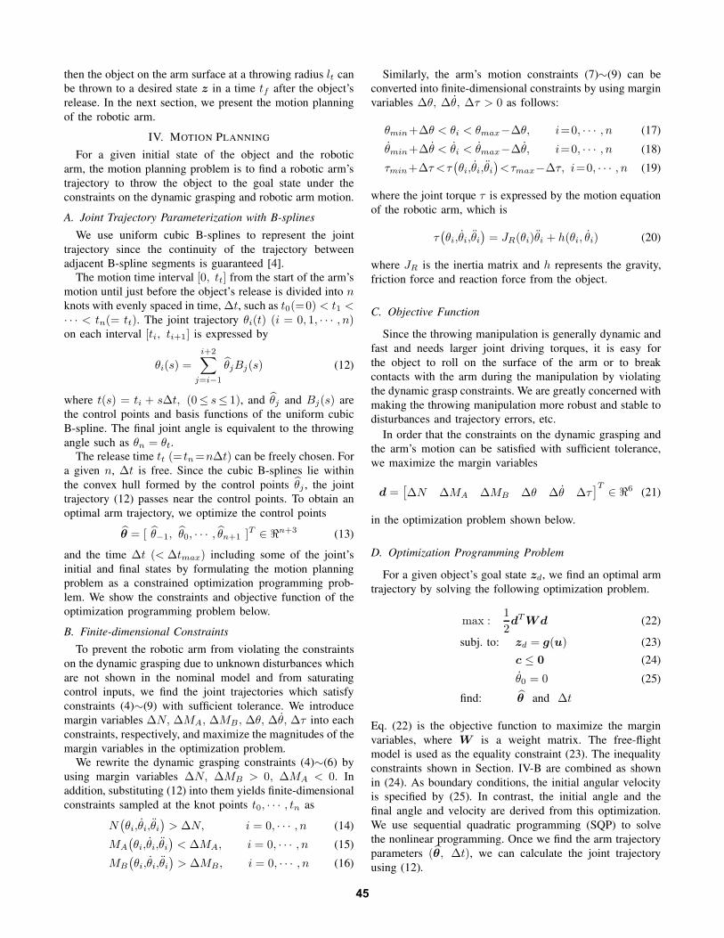
transitions of arm trajectories found by the optimization ateach iteration. The trajectories are modified by repeating thelearning. Fig. 9 shows snapshots of the successful throwingmotion.
In this experiment, it is crucial for the stable and robustthrowing to keep the un-rolling constraint about the vertex Aof the object. In order that the un-rolling constraint (5) canhold and the object will not start rolling on the arm surface,we find the robotic arm trajectory so that the margin ∆MA
become sufficiently large in the optimization problem.
C. Application to Sorting/Assembly Tasks (Attached Video)
The first video shows the trial throwing motion in theiterative learning mentioned above. By repeating the throw-ing, the robotic arm succeeds in throwing the object into thestorage pallet with the zero vertical velocity, which is locatedon the apex point of the object’s ballistic trajectory.
The second video shows the sorting task in which therobotic arm throws three objects into storage pallets withan appropriate orientation, as shown in Fig. 10. In the firstthrowing (Fig. 10(a)), the zero vertical velocity is set at thefirst goal. On the other hand, in the second throwing (Fig.10(b)) we set the negative vertical velocity at the second goal.The object reaches the pallet with descending after passingthrough the apex point of the ballistic trajectory. In the third
47
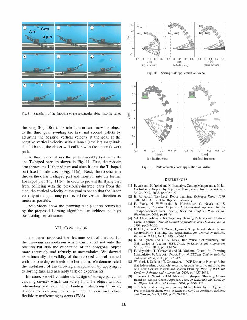
Fig. 9. Snapshots of the throwing of the rectangular object into the pallet
throwing (Fig. 10(c)), the robotic arm can throw the objectto the third goal avoiding the first and second pallets byadjusting the negative vertical velocity at the goal. If thenegative vertical velocity with a larger (smaller) magnitudeshould be set, the object will collide with the upper (lower)pallet.
The third video shows the parts assembly task with H-and T-shaped parts as shown in Fig. 11. First, the roboticarm throws the H-shaped part and slots it onto the T-shapedpart fixed upside down (Fig. 11(a)). Next, the robotic armthrows the other T-shaped part and inserts it into the formerH-shaped part (Fig. 11(b)). In order to prevent the flying partfrom colliding with the previously-inserted parts from theside, the vertical velocity at the goal is set so that the linearvelocity at the goal may put toward the vertical direction asmuch as possible.
These videos show the throwing manipulation controlledby the proposed learning algorithm can achieve the highpositioning performance.
VII. CONCLUSION
This paper proposed the learning control method forthe throwing manipulation which can control not only theposition but also the orientation of the polygonal objectmore accurately and robustly to uncertainties. We showedexperimentally the validity of the proposed control methodwith the one-degree-freedom robotic arm. We demonstratedthe usefulness of the throwing manipulation by applying itto sorting task and assembly task on experiments.
In future, we will consider the design of storage pallets orcatching devices which can surely hold the object withoutrebounding and slipping at landing. Integrating throwingdevices and catching devices will help to construct robustflexible manufacturing systems (FMS).
y [m
]
-0.1 0 0.1 0.2 0.3
-0.1
0
0.1
0.2
0.3
0.4
-0.1 0 0.1 0.2 0.3 -0.1 0 0.1 0.2 0.3
x [m]x [m] x [m]
(a) 1st throwing (b) 2nd throwing (c) 3rd throwing
Fig. 10. Sorting task application on video
-0.1 0 0.1 0.2 0.3 0.4
-0.3
-0.2
-0.1
0
0.1
0.2
0.3
0.4
-0.1 0 0.1 0.2 0.3 0.4
x [m] x [m]
y [
m]
(a) 1st throwing (b) 2nd throwing
Fig. 11. Parts assembly task application on video
REFERENCES
[1] H. Arisumi, K. Yokoi and K. Komoriya, Casting Manipulation, MidairControl of a Gripper by Impulsive Force, IEEE Trans. on Robotics,Vol.24, No.2, 2008, pp.402-415.
[2] E. W. Aboaf, Task-Level Robot Learning, Technical Report 1079,1988, MIT Artificial Intelligence Laboratory.
[3] H. Frank, N. W-Wojtasik, B. Hagebeuker, G. Novak and S.Mahlknecht, Throwing Objects - A bio-inspired Approach for theTransportation of Parts, Proc. of IEEE Int. Conf. on Robotics andBiomimetics, 2006, pp.91-96.
[4] Y-C Chen, Solving Robot Trajectory Planning Problems with UniformCubic B-Splines, Optimal Control Applications and Methods, Vol.12,1999, pp.247-262.
[5] K. M. Lynch and M. T. Mason, Dynamic Nonprehensile Manipulation:Controllability, Planning, and Experiments, Int. Journal of RoboticsResearch, Vol.18, No.1, 1999, pp.64-92.
[6] K. M. Lynch, and C. K. Black, Recurrence, Controllability, andStabilization of Juggling, IEEE Trans. on Robotics and Automation,Vol.17, No.2, 2001, pp.113-124.
[7] H. Miyashita, T. Yamawaki and M. Yashima, Control for ThrowingManipulation by One Joint Robot, Proc. of IEEE Int. Conf. on Roboticsand Automation, 2009, pp.1273-1278.
[8] W. Mori, J. Ueda and T. Ogasawara, 1-DOF Dynamic Pitching Robotthat Independently Controls Velocity, Angular Velocity, and Directionof a Ball: Contact Models and Motion Planning, Proc. of IEEE Int.Conf. on Robotics and Automation, 2009, pp.1655-1661.
[9] T. Senoo, A. Namiki and M. Ishikawa, High-speed Throwing MotionBased on Kinetic Chain Approach, Proc. of IEEE/RSJ Int. Conf. onIntelligent Robotics and Systems, 2008, pp.3206-3211.
[10] T. Tabata, and Y. Aiyama, Passing Manipulation by 1 Degree-of-Freedom Manipulator, Proc. of IEEE Int. Conf. on Intelligent Roboticsand Systems, Vol.3, 2003, pp.2920-2925.
48