Part 1: Introduction/Motivation and Hardware Platformspeters/courses/eecs369/docs/l2-Lecture1... ·...
22
Information Processing in Sensor Networks Peter Scheuermann and Goce Trajcevski Dept. of EECS Northwestern University Email: (peters, goce) @eecs.northwestern.edu Web: http://www.eecs.northwestern.edu/~peters 1 Tel. 847-491-7141 2 Part 1: Introduction/Motivation and Hardware Platforms
Transcript of Part 1: Introduction/Motivation and Hardware Platformspeters/courses/eecs369/docs/l2-Lecture1... ·...

Information Processing in Sensor NetworksPeter Scheuermann and Goce Trajcevski
Dept. of EECS
Northwestern UniversityEmail: (peters, goce) @eecs.northwestern.edu
Web: http://www.eecs.northwestern.edu/~peters
1
Tel. 847-491-7141
2
Part 1:Introduction/Motivation and Hardware
Platforms

3
The Vision Behind Sensor Networks
Embed numerous distributed sensor nodes to onitor and interact with physical world
Exploit spatially and temporally dense, in situ,ensing and actuation
etwork these devices so that they can ordinate to perform higher-level identification d tasks.
ptimize and adapt runtime behavior across distributed system, taking advantage of signed in heterogeneity
4
A Rich Ecology of Platforms: Static, Mobile, Flying, Wearable, Submersible…
dusa MK-2 (UCLA)
RagoBot (UCLA)
otes (UCB)
iBadge (UCLA)
Data Mule(UCLA)
Heliomote(UCLA)
MOTE
STARGATE
PACKBOT
Path Planning
Data Storage
StarGate(Intel)
Helicopter Imager(UCLA)

5
CHARACTERISTICS OF WSNs
Large number of nodes (100s, and even 1000s)Nodes need to be close to each other – communication rangeDensities as high as 20 nodes/m3Asymmetric flow of information, from sensor nodes to sinkCommunications are triggered by queries or eventsLimited amount of energy (in many applications it is impossible to
replace or recharge)Low cost*, size, and weight per nodeProne to failuresMore use of broadcast communications instead of point-to-pointNodes do not have a global ID such as an IP addressThe security, both on physical and communication level, is more limited than in classical wireless networks
6
DIFFERENCES FROM AD-HOC NETWORKS
Number of sensor nodes can be several orders of magnitude higherSensor nodes are densely deployed and are prone to failuresThe topology of a sensor network may change frequently due to node failure and node mobilitySensor nodes are limited in power, computational capacities, and memoryMay not have global ID like IP addressNeed tight integration with sensing tasks

7
Canonical Sensor and Actuator Node
In the future, all integrated on a single chip!
sensors CPU radio
battery
oustic, seismic, ge, magnetic, etc.
interface
Electro-magnetic interface
Limited energy supply
actuatorFar cry from generpurpose computer
CPUs8 b / 8 MHz to 32 b / 400 MStorage2 KB - 64 MB RAM1 MB - 1 GB FlashNo diskRadio38 Kbps / 10 m - 802.11b /mPower30 mW - 3 W
8
Processing System: Memory
Considerations: Speed, capacity, price, power consumption, memory protection
SRAM: typical, 0.5KB-64MB
Typical power consumption
retained: ~100ua; read/write: ~10ma if separate chip
retained: 2ua-100ua, read/write:~5ma if in core
DRAM: high power consumption in retained mode
EEPROM:4KB-512KB, often used as program store
Flash: 256KB-1GB or beyond
Typically used when SRAM power is down and for buffering data Large flashes are outside of core

9
Sensor SubsystemMultiple types of sensors may be used:
Environmental: pressure, gas composition, humidity, light…
Motion or force: accelerometers, rotation, microphone, piezoresistive strain, position…
Electromagnetic: magnetometers, antenna, cameras…
Chemical/biochemical
Digital or analog output
Components:
Transducer
Analog signal conditioning circuits
Analog to digital converter (ADC)
Digital signal processing
10
Transceiver (Radio)
Transceiver unit implements the procedures to convert bits to be transmitted into radio frequency (RF) waves and recovers them at other end. Energy efficiency measure : the energy required to transmit or receive one bit
joules/bit
signal propagation and interference characteristics
difference between receive power versus transmit power
antenna design issues : omnidirectional versus directed

11
Actuation System
Types:
Leds, buzzers, motors, sliders, pumps, gears, solenoids…
Energy consumption (idle: O(uW); active ~1-40 mW)
Startup time (~1ms-1000ms or higher)
Higher voltage planes and noise
Coupling:
Opto-coupler for control
communications, with
encoders for feedback
12
Trade-offs among Nodes
Cap
abili
ties
Size, Power Consumption, Cost
MICA Mote
XYZ
StarGate
•Microprocessor (32b)•Broad Band radio•High performance sensors•Short relative lifetime at continuous operation
•Microcontroller (8 – 16b)•Narrow Band radio•Low bit rate, low performance sensors•Long relative lifetime at continuous operation

13
Design Principles
Key to Low Duty Cycle Operation: Sleep – majority of the time
Wakeup – quickly start processing
Active – minimize work & return to sleep
Transceiver –when not active it is in idle state or sleep stateIdle state—ready to receive but not currently receiving anything
14
Sleep
Majority of time, node is asleep >99%
Minimize sleep current through Isolating and shutting down individual circuits Using low power hardware
Need RAM retentionRun auxiliary hardware components from low speed oscillators (typically 32kHz) Perform ADC conversions, DMA transfers, and bus operations while
microcontroller core is stopped

15
Energy Efficiency vs. Duty Cycling Efficiency
MoteATMega128: CC1000
gate PA255o: 802.11b
CPU Radio
Energy per computation
Sleep Power Startup Cost
Energy per bit
Idle Power StarCo
4 nJ/instr (8b)
31 mJ/beamform30 uW
4 ms
7.2 uJ430 nJ/b 7 mA
Low(~ 10 ms
1.1 nJ/instr (32b)
1 mJ/beamform20 mW
10.6 ms
4.17 mJ90 nJ/b 160 mA
High(~ 10 s)
16
Energy Savings and Overheads for Sleep Modes
If component remains active, energy spent for uselessly idling is:
1( )a c tiv e a c tiv e ev e n tE P t t
Putting the component into sleep mode requires power consumption (Pactive+Psleep)/2 and Psleep
s consumed until tevent , then energy spent is:
1( ) / 2 ( )d ow n a c tive sleep even t do w n sleepP P t t P
17
Energy Savings and Overheads for Sleep Modes
nergy saving:
1 1( ) ( ( ) / 2 ( )s a v e d a c tiv e e v e n t d o w n a c tiv e s le e p e v e n t d o w n sE P t t P P t t P
Additional overhead required to activate the component:
( ) / 2overhead up ac tive sleepE P P
utting component into sleep mode is only beneficial if Eoverhead < Esaved
1
1( ) ( )
2a c tive sleep
even t d o w n u pa c tive sleep
P Pt t
P P
18
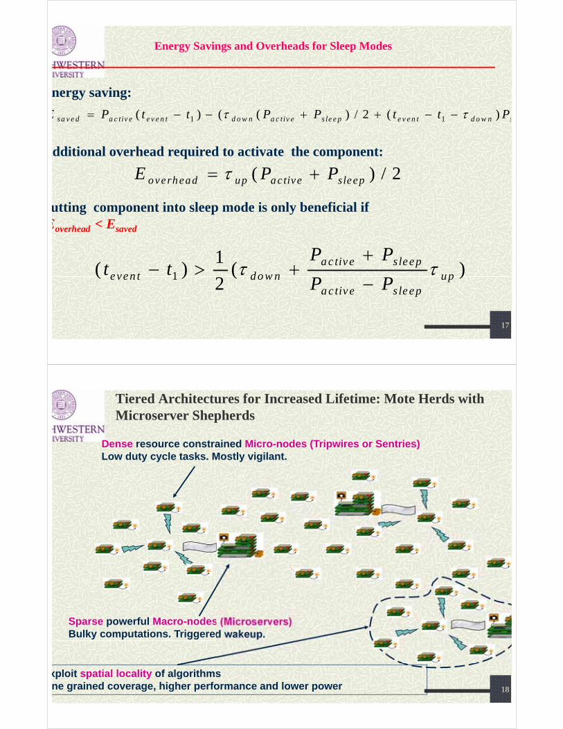
Tiered Architectures for Increased Lifetime: Mote Herds with Microserver Shepherds
Dense resource constrained Micro-nodes (Tripwires or Sentries)Low duty cycle tasks. Mostly vigilant.
Sparse powerful Macro-nodes (Microservers)Bulky computations. Triggered wakeup.
xploit spatial locality of algorithmsne grained coverage, higher performance and lower power

19
Diversity of Application Characteristics
Seismology Ecology Battlefield
Sampling Rate KHz < Hz KHzSampling Density Km Meters MetersSample resolution 24 bit 8 bit 8 bitSpatial Extent 100 Km2 1 Km2 10 Km2
Estimation Fidelity High High HighLatency Minutes-Days Hours-Months SecondsLifetime Months Years WeeksAccess Cost Medium Medium HighPlatform Cost High Medium \High HighPlatform mobility No Yes YesWhere is the answer needed? Centrally Centrally DistributedNature of Task Source Field Source
…Are there reusable architectures, platforms, design tools,run-time services, estimation algorithms etc.?
20
Typical Sensing Application
Periodic Data Collection Network Maintenance Majority of operation
Triggered Events Detection/Notification Infrequently occurs
But… must be reported quickly and reliably
Long Lifetime Months to Years without changing batteries Power management is the key to success
Design principles Sleep: majority of the time (>99%)
Need to optimize for this! Wakeup: quickly start processing Active: minimize work & return to sleep
sleep
processingdata acquisitioncommunication
Po
wer
Time
From Polastre et. al.at Hot Chips 2004
21
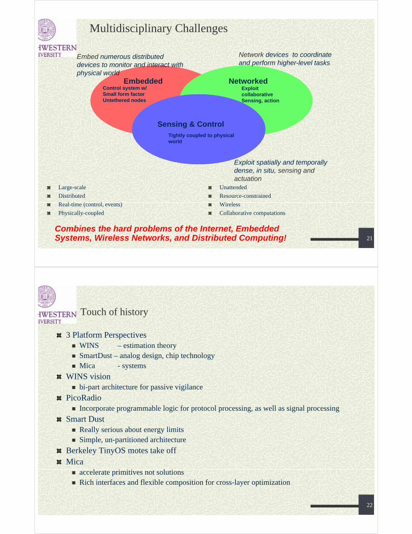
Multidisciplinary Challenges
Large-scale
Distributed
Real-time (control, events)
Physically-coupled
Embedded Networked
Sensing & Control
Control system w/Small form factorUntethered nodes
ExploitcollaborativeSensing, action
Tightly coupled to physical world
Embed numerous distributed devices to monitor and interact with physical world
Network devices to coordinate and perform higher-level tasks
Exploit spatially and temporally dense, in situ, sensing and actuation
Unattended
Resource-constrained
Wireless
Collaborative computations
Combines the hard problems of the Internet, EmbeddedSystems, Wireless Networks, and Distributed Computing!
22
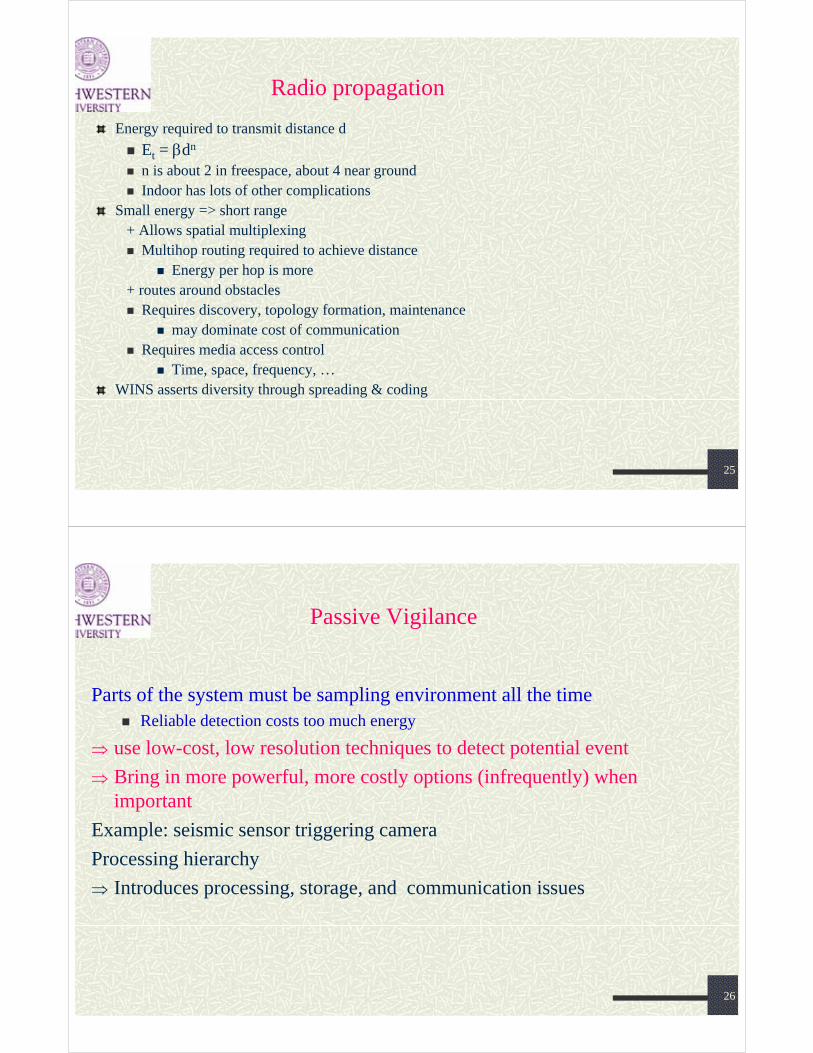
Touch of history
3 Platform Perspectives WINS – estimation theory SmartDust – analog design, chip technology Mica - systems
WINS vision bi-part architecture for passive vigilance
PicoRadio Incorporate programmable logic for protocol processing, as well as signal processing
Smart Dust Really serious about energy limits Simple, un-partitioned architecture
Berkeley TinyOS motes take offMica accelerate primitives not solutions Rich interfaces and flexible composition for cross-layer optimization

23
Emergences of WINS
1994 Pottie and Kaiser propose Low Power Wireless Integrated Microsensor LWIM nodes built around 1996
DARPA Sensit ProgramLate 97-98 handhelds emerge palm ITSY, BWRC PicoRadio, Srivastava UCLA, Chandrakasan MIT, … Matchbox PCs Bluetooth promised
Berkeley SmartDust 1999 WeC mote offshoot
SCADDS (USC/UCLA) pc104s & tags00 Mote / TinyOS platformsWINS ng finally appears in Linux for Sensit02 Mica NEST OEP creates de facto platform03 Bluetooth revival
24
WINS case for distributed sensor nets
Must distribute to detect reliably regardless of $ All signals decay with distance (r^2) + absorption, scattering, dispersion, …even with line
of sight Often need to track multiple objects Obstructions, clustering
Detection and estimation theory observables {Xj} – sample outputs of sensors
target signal plus background noise & interference features {fk} – reduced representation of observations
Fourier, LPC, wavelet coefficients hypotheses {hi} – presence/absence based on estimates of feature set Choose hi if P(hi | {fk} ) > P(hj | {fk} ) for j != i Complexity: dimensions of feature space, # hypotheses=> More observations, rather than more processing per observation=> Short range means better SNR=> Fewer targets (hypotheses) in range of set of sensors=> Nearly homogeneous over small regions Reliability: number of independent observations and SNR
25
Radio propagation
Energy required to transmit distance d
Et = dn
n is about 2 in freespace, about 4 near ground Indoor has lots of other complications
Small energy => short range+ Allows spatial multiplexing Multihop routing required to achieve distance
Energy per hop is more+ routes around obstacles Requires discovery, topology formation, maintenance
may dominate cost of communication Requires media access control
Time, space, frequency, …WINS asserts diversity through spreading & coding
26
Passive Vigilance
Parts of the system must be sampling environment all the time Reliable detection costs too much energy
use low-cost, low resolution techniques to detect potential event
Bring in more powerful, more costly options (infrequently) when important
Example: seismic sensor triggering camera
Processing hierarchy
Introduces processing, storage, and communication issues

27
WINS node architecture
Two-part architecture
Combine network performance info, synch, BW reservations, into data messages
Morphed into Sensoria automotive telematics
www.sensoria.comObserve variant on classical partitioning
28
SENSOR NODE FEATURES (Generic)
Processor/Radio Board MPR300CB
Speed 4 MHz
Flash 128K bytes
SRAM 4K bytes
EEPROM 4K bytes
Radio Frequency 2.4 GHz, 916MHz or 433MHz
Data Rate 40 kbits/sec
Power 0.75 mW
Radio Range 100 feet
Power 2 x AA batteries; Solar Energy

29
Mica“Open
Experimental Platform”
Sensor Motes Timeline
WeC“Smart Rock”
Rene’“Experimentation”
Dot“Scale”
Spec“Mote on a
chip”
Telos“Integrated Platform”
Mica2Dot
Mica2
200620052004200320022001200019991998
IMote
MicaZ
Stargate 2.0&
IMote2
Stargate
30
Examples for Sensor Nodes
ckwell WINS
Smart Dust
JPL Sensor Webs
Dust

31
Examples for Sensor Nodes
MICA Mote
Rene Mote
weC Mote
Dot Mote
32
Current Platforms: 1st Generation
Mica2DOT (2003) 16Kb program mem RFM TR1000 (CSMA/ASK) Lightweight and small
Mica2 & Cricket platform (2003) 128Kb program mem ChipconCC1000 (CSMA/FSK) 40Khz Ultrasounders (Cricket only)
MicaZ (2004) & Telos (2005) 802.15.4/Zigbee stack Spread Spectrum radio handles multipath better Integrated antenna (Telos only)

33
Current Platforms: 2nd Generation
Imote (2003) & Imote2
Higher processing power Bluetooth & 802.11 capable (Imote2 only)
Stargate (2005) & Stargate 2.0 Pentium class processor Linux OS => easy development (C/C++) More processing capabilities => energy intensive 802.11 capable
34
The Mote Family
From Polastre et. al.at Hot Chips 2004

35
Berkeley Motes (Details)
36
MICAz PlatformMicroprocessor: Atmel ATmega128L
• 7.3728 MHz clock• 128 kB of Flash for program memory• 4 kB of SRAM for data and variables• 2 UARTs (Universal Asynchronous Receive and Transmit)• Serial Port Interface (SPI) bus• Dedicated hardware I2C bus
Radio: Chipcon’s CC2420 (IEEE 802.15.4) 250 kbit/sxternal serial flash memory: 512 Kb xbow estimates > 100000 samples1-pin expansion connector Eight 10-bit analog I/O 21 general purpose digital I/O
User interface: 3 programmable LEDsowered by two AA batteries 1850 mAh capacity
Logger Flash
ATMega128LcontrollerAnalog I/ODigital I/O
Freq. Tunable Radio
51-Pin
Exp
ansio
n C
on
necto
r
Antenna
MMCX connector
LE
Ds

37
Telos Platform
Robust USB interface
Integrated antenna (30m-125m)
External antenna capability (~500m)
High Performance 10kB RAM, 48 KB ROM
12-bit ADC and DAC (200ksamples/sec)
Hardware link-layer encryption
38
Telos by MOTEIV.com
Single board philosophy
Robustness, Ease of use, Lower Cost
Integrated Humidity & Temperature sensor
First platform to use 802.15.4
CC2420 radio, 2.4 GHz, 250 kbps
Motorola HCS08 processor
Lower power consumption, 1.8V operation, faster wakeup time
40 MHz CPU clock, 10K RAM; 48K Flash
50m indoor; 125m outdoor ranges
39
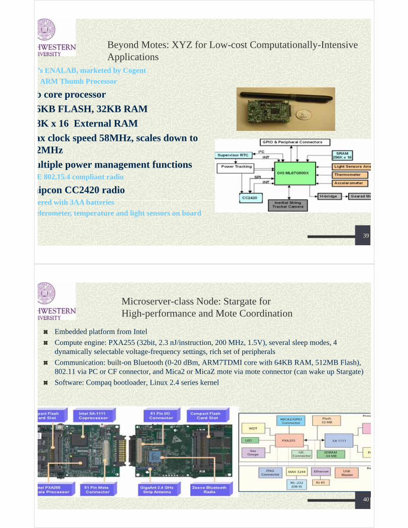
Beyond Motes: XYZ for Low-cost Computationally-Intensive Applications
’s ENALAB, marketed by Cogent
I ARM Thumb Processor
b core processor
6KB FLASH, 32KB RAM
8K x 16 External RAM
ax clock speed 58MHz, scales down to 2MHz
ultiple power management functionsE 802.15.4 compliant radio
hipcon CC2420 radioered with 3AA batteries
elerometer, temperature and light sensors on board
40
Microserver-class Node: Stargate forHigh-performance and Mote Coordination
Embedded platform from Intel
Compute engine: PXA255 (32bit, 2.3 nJ/instruction, 200 MHz, 1.5V), several sleep modes, 4 dynamically selectable voltage-frequency settings, rich set of peripherals
Communication: built-on Bluetooth (0-20 dBm, ARM7TDMI core with 64KB RAM, 512MB Flash), 802.11 via PC or CF connector, and Mica2 or MicaZ mote via mote connector (can wake up Stargate)
Software: Compaq bootloader, Linux 2.4 series kernel

41
SENSOR NETWORKS FEATURES
APPLICATIONS: Military, Environmental, Health, Home, Space Exploration, Chemical Processing, Volcanoes, Mining, Disaster Relief….
SENSOR TYPES: Seismic, Low Sampling Rate Magnetic, Thermal, Visual, Infrared, Acoustic, Radar…
SENSOR TASKS:Temperature, Humidity, Vehicular Movement, Lightning Condition, Pressure, Soil Makeup, Noise Levels, Presence or Absence of Certain Types of Objects, Mechanical Stress Levels on Attached Objects, Current Characteristics (Speed, Direction, Size) of an Object ….
42
Sensor Types
Light Thermopile Ultraviolet IR Visible Light Color sensors
MagneticSound Ultrasound
AccelerometersTemperature sensorsPressure sensorsHumidityTouch sensors
2.25 inMicrophone
Accelerometer
Light TemperaSounder
Magnetometer
1.25 in

43
Dot Weather Boards
“Dot” sensorboards (1” diameter)
HoneyDot: Magnetometer
Resolution: 134 Gauss
Ultrasonic Transceiver
Weather Station
44
Applications of Stargate
Seismic monitoring, personal exploration rover, mobile micro-servers, networked info-mechanical systemshierarchical wireless sensor networks
[NIMS, UCLA][Robotics, CMU] [NESL, UCLA]
[CENS, UCLA] [Intel + UCLA]