
Par2: a Spatial Mechanism for Fast Planar, 2-dof, Pick-and ...
11
HAL Id: lirmm-00305178 https://hal-lirmm.ccsd.cnrs.fr/lirmm-00305178 Submitted on 23 Oct 2008 HAL is a multi-disciplinary open access archive for the deposit and dissemination of sci- entific research documents, whether they are pub- lished or not. The documents may come from teaching and research institutions in France or abroad, or from public or private research centers. L’archive ouverte pluridisciplinaire HAL, est destinée au dépôt et à la diffusion de documents scientifiques de niveau recherche, publiés ou non, émanant des établissements d’enseignement et de recherche français ou étrangers, des laboratoires publics ou privés. Par2: a Spatial Mechanism for Fast Planar, 2-dof, Pick-and-Place Applications Cédric Baradat, Vincent Nabat, Olivier Company, Sébastien Krut, François Pierrot To cite this version: Cédric Baradat, Vincent Nabat, Olivier Company, Sébastien Krut, François Pierrot. Par2: a Spatial Mechanism for Fast Planar, 2-dof, Pick-and-Place Applications. Fundamental Issues and Future Research Directions for Parallel Mechanisms and Manipulators, Sep 2009, Montpellier, France. pp.10. lirmm-00305178
Transcript of Par2: a Spatial Mechanism for Fast Planar, 2-dof, Pick-and ...

HAL Id: lirmm-00305178https://hal-lirmm.ccsd.cnrs.fr/lirmm-00305178
Submitted on 23 Oct 2008
HAL is a multi-disciplinary open accessarchive for the deposit and dissemination of sci-entific research documents, whether they are pub-lished or not. The documents may come fromteaching and research institutions in France orabroad, or from public or private research centers.
L’archive ouverte pluridisciplinaire HAL, estdestinée au dépôt et à la diffusion de documentsscientifiques de niveau recherche, publiés ou non,émanant des établissements d’enseignement et derecherche français ou étrangers, des laboratoirespublics ou privés.
Par2: a Spatial Mechanism for Fast Planar, 2-dof,Pick-and-Place Applications
Cédric Baradat, Vincent Nabat, Olivier Company, Sébastien Krut, FrançoisPierrot
To cite this version:Cédric Baradat, Vincent Nabat, Olivier Company, Sébastien Krut, François Pierrot. Par2: a SpatialMechanism for Fast Planar, 2-dof, Pick-and-Place Applications. Fundamental Issues and FutureResearch Directions for Parallel Mechanisms and Manipulators, Sep 2009, Montpellier, France. pp.10.�lirmm-00305178�

Proceedings of the Second International Workshop on Fundamental Issues and Future Research Directions for Parallel Mechanisms and Manipulators
September 21–22, 2008, Montpellier, France N. Andreff, O. Company, M. Gouttefarde, S. Krut and F. Pierrot, editors
1
Par2: a Spatial Mechanism for Fast Planar, 2-dof, Pick-and-Place Applications
CEDRIC BARADAT, VINCENT NABAT FATRONIK France - Cap Omega
Rond-point Benjamin Franklin - CS 39521 34960 Montpellier Cedex 2, France <cbaradat, vnabat>@fatronik.com
OLIVIER COMPANY, SEBASTIEN KRUT, FRANÇOIS PIERROT LIRMM – UMR 5506 CNRS - University Montpellier II
161 rue Ada, 34392 Montpellier Cedex 5, France <company, krut, pierrot>@lirmm.fr
Abstract: This paper introduces a new two-degree-of-freedom parallel manipulator producing two translations in the vertical plane. The classical drawback of the existing robots built to realize those dof is their lack of rigidity along the transversal axis. Indeed, these architectures cannot be lightweight and stiff at the same time. The proposed architecture is a spatial mechanism which guarantees a good stiffness along the transversal axis. This parallel architecture is composed by two actuated kinematic chains, and two passive chains built in the transversal plane. The key feature of this robot comes from those passive chains which are linked to the frame using coupled revolute joints. This coupling system guarantees the functioning of the robot by constraining the platform to stay in one plane. The stiffness analysis presented in this paper shows that the robot can be lighter and stiffer than a classical 2 dof mechanism. A prototype of this robot has been built and the preliminary tests show that accelerations of 23 g can be achieved while keeping a low tracking error.
1 Introduction The first parallel mechanism is attributed to Gough with
its well-known platform [1] and Stewart [2] created a flight simulator few years later using a similar architecture. Thanks to actuators located close to the frame, the dynamic capabilities of these mechanisms are high compared to serial robots. These machines have six degrees of freedom (dof).
However, all robotized tasks do not need six dof. Brogardh proposed a classification [3] giving the necessary number of dof for different industrial tasks. Generally, pick-and-place applications need four dof: three translations and one rotation around a vertical axis. Nevertheless, some simple operations need only two degrees of freedom in order to transfer a part from a working area to another one (e.g. conveyors). A lot of 2 dof parallel mechanisms have been developed (see § 2), but all of them are built as planar mechanisms, or more precisely built “in a plane”. However, even if the robot motion is done in that plane, a minimum stiffness has to be guaranteed in the direction perpendicular to the plane to limit vibrations; being stiff in the direction perpendicular to the plane means resisting to bending and torsion effects and leads to high-inertia, high-mass parts.
This paper presents a new architecture developed to perform 2-dof pick-and-place, that is providing a planar motion, but not being designed in a plane. The key issue in this work is to look for a lightweight mechanism for planar motion, stiff enough in all directions to sustain very high accelerations.
First of all, this paper presents a few existing 2 dof parallel robots. Then, a complete description of the new architecture is done and its modeling is presented. Finally, the prototype and the first experimental tests realized with the robot are presented.
2 A Few Existing Mechanisms Most 2 dof robots used in industry for pick-and-place
operations make 2 translations and maintain the orientation of the platform constant. Besides the obvious solution of serial chain (2 prismatic joint), several solutions involving closed kinematic chains have been proposed, and most of them resort to a planar parallelogram (a Π joint [4]1) to create the constraint which keeps the moving platform orientation constant.
The mechanism described by Brogårdh in [5] (Figure 1) has a Π link situated between the prismatic drives and the end-effector. Figure 1b and 1c show two different representations for the Π linkage. Figure 1b shows the complete representation, 4 cylindrical joints in closed chains. Figure 1c shows the simplified representation of the linkage.
Equivalent mechanisms can also be created using rotational drives instead of prismatic drives, as shown in Figure 2. Figure 2-a shows a solution where a moving platform is constrained by two Π joints, and actuated by a serial R-R chain (R stands for revolute joint); Figure 2-a shows an equivalent solution where the actuation is made with a planar closed chain and the constrain with a modified set of 2 Π joints (aiming at singular positions avoidance).
It is also possible to actuate directly the Π joints, for example by acting on them with R-P-R chains as in figure 3 (P stands for prismatic joint), resulting in a smaller moving platform but creating high bending forces in the parts. 1 Kinematic chain description: R stands for revolute joint, P for prismatic joint, and Π for Π joint. The joint is measured when the letter is underlined, and is actuated when the letter is in bold type.

2
Finally the over-constrained mechanism proposed by Liu [6] uses Π linkages to join the platform with two prismatic actuators placed in vertical position (Figure 4: the design concerns a machine-tool with a moving table as 3rd axis).
Figure 1: constant orientation platform and prismatic drives
(a) (b)
Figure 2 : constant orientation platform and rotational drives
Figure 3 : actuating the Π linkages
Figure 4 : Over-constrained mechanism with prismatic drives
3 Planar or Spatial Mechanisms for Planar Motion? Obviously, the easiest way to obtain a 2-translation planar
motion is to resort to a serial P-P chain (A1 in Table1); however, acceleration and speed will be limited by the capabilities of linear drives (the mechanism cannot amplify anything), and the moving parts has to sustain bending forces. A serially actuated R-R chain, together with an additional parallel chain to create the kinematic constrain (A2) may offer better speed (depending on the arms’ length), but will suffer from too large moving masses (one actuator has to be carried; heavy parts are needed to sustain bending forces). Adding one chain offers the possibility to move the second actuator back to the frame (A3) and shares the actuation between the left chain and the parallelogram; bending problem still exists for forces perpendicular to the plane of motion. Finally, one may think in separating “actuation” and “constraint”: the mechanism (A4) has a parallel linkage made of two R-S-S chains which provide the driving forces onto the moving platform (in the plane of motion), and a constraint chain able (i) to keep the platform orientation constant and (ii) to sustain the forces perpendicular to the plane and all three moments (again, this last chain has to be designed with heavy elements able to sustain bending).
TABLE 1: A few classical mechanisms able to produce the
necessary 2 dof
A1 – Cartesian structure A2 – Serial structure with embedded
parallelograms
A3 – Parallel structure with embedded parallelograms
A4 - Parallel structure with auxiliary parallelograms
The cornerstone of this paper is to analyze the possibility
to take advantage of non-planar mechanisms for designing robots with planar motion; more precisely, the idea is to look for ways to support the 3 moments (Mx, My, Mz) and the force perpendicular to the plane of motion (Fy) in a different manner. Table 2 shows a few possible solutions: - in (B1), a chain is added “out of the motion plane” and
supports My (the chain is a passive R-(SS)2, Delta-like chain); the parts remaining “in the plane” still have to sustain the remaining forces and moments;
R P R
Pla
tfor
m
Π
R
Π
P R
Fra
me
y
z
x
Π
Π P
Fra
me
P Pla
tfor
m
(a) representation of mechanism
P R
Pla
tfor
m
R F
ram
e
R
R
R
R
Π
R R
(b) joint and loop graph
(c) joint and loop graph using the
Π joint representation
Fra
me
Pla
tfor
m
P
P
P
x y
z
x
y z
x
y z
x
y z
3
- in (B2), the left chain supports Fy and Mz thanks to an outer arm made with 4 links with S joints at each end; comparing with (A3), each element of this outer arm works only in tension-compression and not in bending;
- in (B3), a Delta-like mechanism is modified: the arm on the right-hand side is actuated, but the two arms on the left-hand side are passive, and linked together to a single actuation chain; a motion of this chain results in identical motions for both passive chains of the left-hand side;
- in (B4), previous idea is pushed a step further; 4 passive chains arranged as for Par4 mechanisms are coupled two-by-two and driven by two actuated chains; here, both passive on the left-hand side move in identical way (and the same is true on the right-hand side);
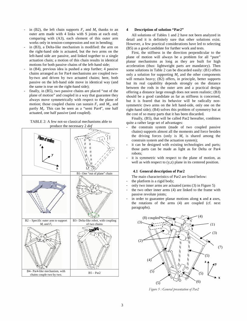
- finally, in (B5), two passive chains are placed “out of the plane of motion” and coupled in a way that guarantee they always move symmetrically with respect to the plane of motion; those coupled chains can sustain Fy and My, and partly Mz. This can be seen as a “semi Par4”, one half actuated, one half passive (and coupled).
TABLE 2: A few not-so classical mechanisms able to
produce the necessary 2 dof
B1- One “out of plane” chain
B2 – Specific outer arm to support
Mz and Fy B3– Delta-like robot, with coupling
of two chains
B4– Par4-like mechanism, with
chains couple two by two. B5 – Par2
4 Description of solution “Par2” All solutions of Tables 1 and 2 have not been analyzed in
detail and it is definitely sure that other solutions exist. However, a few practical considerations have led to selecting (B5) as a good candidate for further work and tests.
First, the stiffness in the direction perpendicular to the plane of motion will always be a problem for all “pure” planar mechanisms as long as they are built for high acceleration (thus: lightweight parts are mandatory). Then some solutions in Table 2 can be discarded easily: (B1) offers only a solution for supporting My and the other components will remain heavy; (B2) offers, in principle, better supports but its real capability depends strongly on the distance between the rods in the outer arm and a practical design offering a distance large enough does not seem realistic; (B3) should be a good candidate as far as stiffness is concerned, but it is feared that its behavior will be radically non-symmetric (two arms on the left hand-side, only one on the right-hand side); (B4) solves this problem of symmetry but at the cost of so many parts that it has been discarded.
Finally, (B5), that will be called Par2 hereafter, combines quite a rather large set of advantages: - the constrain system (made of two coupled passive
chains) supports almost all the moments and force besides the driving forces (only is Mz is shared among the constrain system and the actuation system);
- it can be designed with existing technologies and parts; those parts can be made as light as for Delta or Par4 robots;
- it is symmetric with respect to the plane of motion, as well as with respect to (y,z) plane in its centered position.
4.1 General description of Par2 The main characteristics of Par2 are listed below:
- the platform is a rigid body; - only two inner arms are actuated (arms (3) in Figure 5) - the two other inner arms (4) are linked to the frame with
passive revolute joints; - in order to guarantee planar motions along x and z axes,
the rotations of the arms (4) are coupled (cf. next paragraphs).
Figure 5 : General presentation of Par2
(7)
(1)
(2)
(3)
(3)
(4)
(4)
(5)
(5)
(5)
(5)
(6)
(8) coupled
x
y z
z
x
y
4
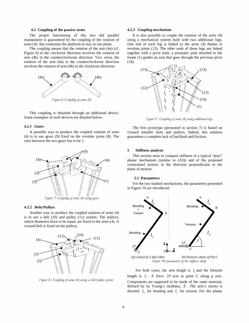
4.2 Coupling of the passive arms The proper functioning of this two dof parallel
manipulator is guaranteed by the coupling of the rotation of arms (4): this constrains the platform to stay in one plane.
The coupling means that the rotation of the arm (4a) (cf. Figure 6) in the clockwise direction involves the rotation of arm (4b) in the counterclockwise direction. Vice versa, the rotation of the arm (4a) in the counterclockwise direction involves the rotation of arm (4b) in the clockwise direction.
Figure 6: Coupling of arms (4)
This coupling is obtained through an additional device. Some examples of such devices are detailed below:
4.2.1 Gears
A possible way to produce the coupled rotation of arms (4) is to use gears (9) fixed on the revolute joints (8). The ratio between the two gears has to be 1.
Figure 7: Coupling of arms (4) using gears
4.2.2 Belts/Pulleys
Another way to produce the coupled rotation of arms (4) is to use a belt (10) and pulley (11) system. The pulleys, which diameters have to be equal, are fixed to the arms (4). A crossed belt is fixed on the pulleys.
Figure 8 : Coupling of arms (4) using a belt/pulley system
4.2.3 Coupling mechanism
It is also possible to couple the rotation of the arms (4) using a mechanical system built with two additional legs. One end of each leg is linked to the arms (4) thanks to revolute joints (13). The other ends of these legs are linked together with a pivot joint; a prismatic joint attached to the frame (1) guides an axis that goes through the previous pivot (14).
Figure 9 : Coupling of arms (4) using additional legs The first prototype (presented in section 7) is based on
crossed metallic belts and pulleys. Indeed, this solution guarantees a complete lack of backlash and friction.
5 Stiffness analysis This section aims to compare stiffness of a typical “pure”
planar mechanism (similar to (A3)) and of the proposed constrained system, in the direction perpendicular to the plane of motion.
5.1 Parameters For the two studied mechanisms, the parameters presented
in Figure 10 are introduced.
(a) classical 2 dof robot (b) Passive chain of Par2
Figure 10: parameters of the stiffness study
For both cases, the arm length is al and the forearm
length is fl . A force 2F acts at point C along y axis.
Components are supposed to be made of the same material, defined by its Young’s modulus, E . The arm’s inertia is denoted bI for bending and tI for torsion. For the planar
z
fl
Bending +
Torsion
C
B
A
2F
al
C
B
A
2Fβ
Bending
Tension
al
flBending
xy
(4a) (4b)
(4) (4)
(2)
(9)
(3) (1)
(3)
(4) (11) (11) (10)
(2)
(12) (12)
(13) (13)
(1)
(14)

5
mechanism, the forearm is supposed to have the same inertias as the arm.
5.2 Study of a classical planar mechanism The force 2F creates bending in the forearm, and
bending plus torsion in the arm. The bending effect on the arm creates a small displacement of point B (and consequently, of point C):
3
1 3a
b
F l
EIδ = (1)
When the arm is supposed to be infinitely rigid, the bending effect on the forearm creates a small displacement of point C:
3
2 3f
b
F l
EIδ = (2)
Under the torsion effects, if the shear modulus is noted G , the arm is twisted by an angle aα such as:
* *
*a f
at
l F l
G Iα = (3)
which results, under the assumption of small displacements, in an additional displacement of point C:
3
* *
*a f
ft
l F ll
G Iδ = (4)
Thus, those three effects can be combined to get the total displacement of point C along the y axis:
2 33
/ 3 3a f fa
C yb t b
F l l F lF l
E I G I E Iδ = + + (5)
5.3 Study of Par2 mechanism The external force creates tension in the forearm, bending
in the arm and some deformation in the coupling mechanism (Figure 11).
Figure 11: Forces applied on the passive chains
The force 2F creates a tension force in the
forearm: / cosF β ; this tension leads to the following
deformation:
cos
ff
F ll
S Eδ
β= (6)
In addition, the bending of the arm creates a small displacement of point B in the direction of the forearm:
3
/1 3cosa
Bb
F l
EIδ
β= (7)
If the coupling mechanism stiffness in torsion is denotedη , and considering it is loaded with a torque equals
to / cosaF l β , an additional small displacement of point B in
the direction of the forearm can be expressed as:
/ 2 cosa
B a
F llδ
η β= (8)
Finally, the deformations are in the direction of the forearms. It leads to a small displacement of point C expressed as follow:
( )3 2
/ /1 / 2 cos3
f a aC y f B B
b
F l F l F ll
S E EIδ δ δ δ β
η= + + = + + (9)
5.4 Simplified case study In order to compare the two previous studies, the
following hypotheses are done: - the arm (and forearm in the case of the planar
mechanism) is a cylindrical pipe, with external and internal diameters denoted D and d ;
- for the proposed mechanism, forearm is made of two cylindrical tubes, with external and internal diameters denoted 'D and 'd .
- 2f al l=
It leads to:
4 4 4 4
, 232 64t b t b
D d D dI I I I Iπ π− −= = ⇒ = = (10)
For material as steel ( 112E e Pa= ; 108G e Pa= ) or
aluminum alloys ( 106.9E e Pa= ; 102.7G e Pa= ), we can assume that:
5
2E G≈ (11)
Thus, the displacement of point C in the case of a planar mechanism can be given as follow:
3 3 3 3
/
5
24 8 3f f f f
C y
Fl Fl Fl Fl
E I E I E I E Iδ = + + = (12)
Regarding the Par2 mechanism, the cross section of both
cylinders is given by:
( )2 22 ' '4
S D dπ= − (13)
Let’s assume that the cylinders for Par2 are 4 times smaller than the one used for the classical mechanism (ensuring the proposed mechanism is well suited for high speed):
1 1' and '
4 4D D d d= =
This gives an overall cross section 8 times smaller:
( )2 2
32S D d
π= −
Thus, the tension in a forearm can be expressed:
2F β
cosF
β
cosF
β
Bδ
Bδ
6
( )2 2
32cos f f
f
F l F ll
S E D d Eδ β
π= =
− (14)
The bending is computed by the following expression:
( )3 33
/1 4 4
32cos
3 24 12f fa
Bb
Fl FlF l
EI E I E D dδ β
π= = =
− (15)
It is worth noting that:
- the effect of arm bending on the displacement of point C is 24 times smaller than the total displacement in the case of the planar mechanism
- the effect of forearm tension can reasonably be neglected2 compared to the effect of arm bending
- it is then sufficient to select a coupling mechanism with a correct stiffness in torsion to guarantee that the proposed mechanism is as stiff, or even stiffer than the equivalent planar mechanism.
If the coupling mechanism is a belt-and-pulley system,
its stiffness can be analyzed, in first approximation, as follows:
- Deformation of the belt blδ (only the free length bl that
is not in contact on the pulleys …):
b bb
b b
F ll
S Eδ = (16)
where bF is the force on the belt, bS the section of the belt
and bE its Young modulus
- Resulting small angular displacement of the pulley:
bp
p
l
r
δα = (17)
with br , the radius of the pulley
- Equivalent stiffness:
2b p b b p
p b
F r S E r
lη
α= = (18)
Then,
2
/ 2 cos b aB
b b p
F l l
S E rδ β
=
(19)
In conclusion, the deformation of point C in the case of the Par2 mechanism can be expressed as follows:
3 2 3 2
/ 3 3f a a a a
C yb b
F l F l F l F l F l
S E EI EIδ
η η= + + ≈ + (20)
2 Indeed, even with a forearm 8 times lighter than for the planar mechanism, the tension effect remains very small compared to the bending effect:
( )( )
4 4
2 2 2/1
12f
B f
D dl
D d l
δδ
−=
−, ( )22 22 2D D e De e De− − = − ≈
( ) ( )( ) ( )2 24 24 4 4 2 32 4D D e D D e D D De D e− − = − − ≈ − − ≈
2
/1
24f
B f
l D
l
δδ
≈
(if 360D e m−= and 1fl m= ,
/1
0.1f
B
lδδ
< )
In order to have a numerical comparison between the two studied cases, we propose to consider the following case study:
D = 60 mm d = 50 mm E = 6.9 e10 Pa G = 2.7 e10 Pa. In addition, concerning the Par2 robot, we assume that:
112bE e Pa=
( )6 25 20 0.25bS e m mm mm−= ×
0.1pr m=
0.1bl m=
The obtained numerical results are: - classical planar mechanism: 6
/ / 44.6 /C y F e m Nδ −=
- Par2 mechanism: 6/ / 4.3 /C y F e m Nδ −≈
Those simple calculations show that even with lighter
parts, Par2 is able to offer stiffness 10 times higher than a classical planar mechanism.
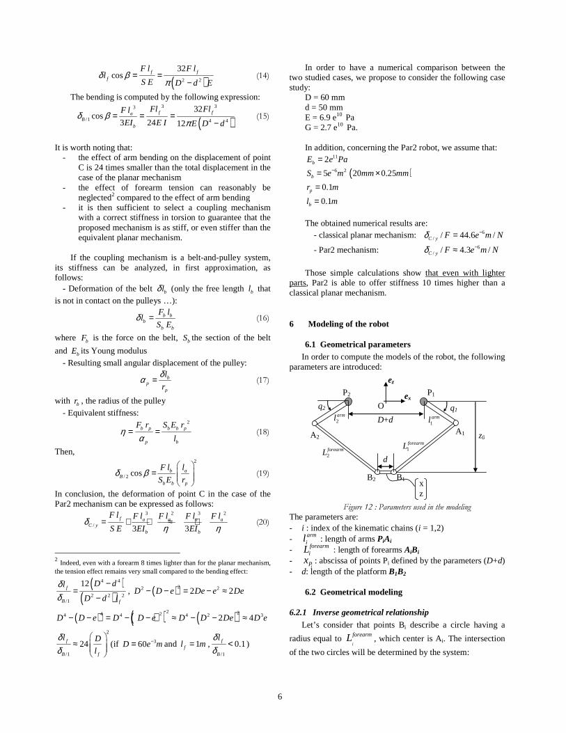
6 Modeling of the robot
6.1 Geometrical parameters In order to compute the models of the robot, the following
parameters are introduced:
D+d
z0
q1
x z
O
ez
ex
d
2arml
2forearmL
1arml
1forearmL
q2
P2 P1
A1 A2
B2 B1
Figure 12 : Parameters used in the modeling
The parameters are: - i : index of the kinematic chains (i = 1,2) - arm
il : length of arms PiAi - forearm
iL : length of forearms AiBi -
iPx : abscissa of points Pi defined by the parameters (D+d) - d: length of the platform B1B2
6.2 Geometrical modeling
6.2.1 Inverse geometrical relationship
Let’s consider that points Bi describe a circle having a
radius equal to i
forearmL , which center is Ai. The intersection
of the two circles will be determined by the system:

7
1 1 1 2 1 1
2 2 2 2 02 2
( ( cos( ))² ( sin( ))²
( ( cos( ))² ( sin( ))²
arm arm forearmp
arm arm forearmp
x x l q z l q L
x x l q z l q L
− + + + = − + + + =
(21)
It leads to a classical resolution:
.sin( ) .cos( ) 0 ( 1,2)i i i i iI q J q K i+ + = = (22)
With :
( )( )
2
2
2 ; 2 2 .
.4
2 .
i
i
i i
arm armi i i P i
armi P i
forearmP P i
I zl J ( x x h) l
d²K x² x ² l x h
x x h.x z² L
= = − −
= + + + +
− − + −
(23)
Using the variable ( )tan / 2i it q= leads to the resolution
of system (21):
2arctan i ii
i i
I ∆q
K J
− ± = −
(24)
Where i i i i∆ I ² J ² K ²= + −
Note that the correct solution for each joint value is determined by selecting the one placed in the good quadrant.
6.2.2 Forward geometrical relationship
This calculation can be done by writing the system (21) in the following form:
( )( )
2
1forearm
a a
forearmb b
(x x )² (z z )² L ²
(x x )² (z z )² L ²
− + − =
− + − =
(25)
With:
1 21 1 2 2
1 1 2 2
cos cos2 2,
sin sin
arm arma P b P
arm arma b
d dx x l . (q ) x x l . (q )
z l . (q ) z l . (q )
= − + + = − + − = − = −
(26)
The difference between the two equations of (25) leads to:
2x zα β= + (27)
where,
( ) ( )1
2 2
2 1
2
,
2
a b
a b
forearm forearma b a b
a b
z z
x x
x ² x ² z ² z ² L L
(x x )
α
β
−= −
−
− + − + −=
−
(28)
Then, it is possible to write the first equation of (25) using expression (27). It gives the following polynomial equation:
0z² zϕ ψ λ+ + = (29)
Thus, z is calculated by solving equation (29). This resolution will give two solutions for z. The correct one will be kept by choosing the lower value. It is now possible to determine the value of x thanks to equation (27).
6.2.3 Kinematical modeling
The kinematical modeling consists in calculating the jacobian matrix that can be defined by two matrices, such as:
= -1x qJ J J (30)
Those two matrices can be determined by using the equiprojectivity propriety of the velocities in the forearms:
. .i i i i=i iA BV A B V A B (31)
where iAV and
iBV are the vectors giving respectively the
velocities of points Ai and Bi.
It leads to the following result:
1 1 1 1
2 2 2 2
. .
. .x z
x z
=
x
A B e A B eJ
A B e A B e (32)
and
( )
( ) ( )1 1 1 1
2 2 2 2
. 0
0 .
y
yq
×=
×
−
A B P A e
A B P A eJ (33)
6.3 Simplified dynamic modeling In order to make the choice of the robot actuation, the
torques to be delivered by the motors have to be determined. An estimation of this torque can be obtained by computing a simplified dynamic model of the robot [8]. Note that this simplified modeling assumes that friction is negligible and the effects of the passive chains are neglected. The required torque is the sum of the torques due to the effects of the actuator, the kinematic chain and the platform:
act kin pla= + +τ τ τ τ (34)
The following development includes many simplifications that are not detailed in this document, but are explained in [9].
6.3.1 Torque due to the actuator
The torque due to the motor and reducer is given by: act act= ɺɺτ I q (35)
with qɺɺ , vector of the joint accelerations
actI , matrix of inertias expressed in the frame at the output
of the reducer
6.3.2 Torque due to the kinematic chain
Figure 13: Modeling of a kinematic chain
The contribution of the kinematic chain on the actuation torque is function of:
Arm inertia and mass ( )cosarm arm arm Gg l= −ɺɺτ I q q M (36)
with
q , vector of the joint positions iq (i = 1,2)
Mforearm
0≈forearmi
Marm
lG
G
2forearmm

8
Gl , distance between the rotation axis and the center of mass
G
armM , vector of the masses of the arms
armI , inertia of the arm
g , gravity acceleration
The mass of the forearm is split in two parts and artificially considered on both ends of the forearm, which means half of the mass is transferred and the end of the arm, and the other half is transferred on the platform [10].
( )( )cos 2 armforearm forearm forearm ig l= −ɺɺτ I q q M (37)
with
forearmI , inertia of the forearm
i
arml , length of one of the arms (assuming that 1 2arm arml l= )
forearmM , vector of the masses of the forearms
Finally, the torque due to the kinematic chain is:
( )
( )( )cos
cos 2i
kin arm arm G
armforearm forearm
g l
g l
= −
+ −
ɺɺ
ɺɺ
τ I q q M
I q q M (38)
6.3.3 Torque due to the platform (and the load) plaτ
The torque due to the platform and the two forearms is given by:
( )( )Tpla pla forearm= + +ɺɺτ J M M x g (39)
with
J , the Jacobean matrix of the robot
plaM , vector of the mass of the platform (and the load)
ɺɺx , acceleration of the robot in the Cartesian space
6.3.4 Total torque Finally, the torque required to set the move to the end-effector is:
( )( )( )
( )( )
cos
cos 2
arm arm G
armforearm forearm i
Tpla forearm
g l
g l
= −
+ −
+ + +
ɺɺ
ɺɺ
ɺɺ
τ I q q M
I q q M
J M M x g
(40)
All those models give indispensable tools for the design
and for the control of the robot. Thus, thanks to all these studies, a prototype of the mechanism has been built and some tests have been performed to validate the good behavior of robot running at very high accelerations.
7 Prototype and experimentations
7.1 Research of the geometrical parameters using optimization
The design of fast mechanisms requires optimization of the actuation but also optimization of the mechanical design
because of huge efforts and constraints produced by the motion of the end-effector.
The specifications of the problem are the following: a motion with a 2 kg payload along an “Adept cycle” path of 700mm length and 25mm height, in less than 0.25s. The equivalent velocity and acceleration of the platform are respectively 8m.s-1 and 300 m.s-2 (about 30G).
The chosen actuators are TPM50 Alpha motors coupled with gears having a reduction ration of 21. Note that during a high acceleration motion of an actuated system, a part of the torque given by the motors is consumed by the acceleration of the geared-motor itself. This effect has been taken into account.
An optimization of the geometrical parameters has been done. The aim is to determine the best dimensioning of the robot based on the actuator characteristics and the required robot. The results of this optimization are given in the following figure.
-0.6 -0.4 -0.2 0 0.2 0.4
-0.8
-0.6
-0.4
-0.2
0L0.825 l0.375 D0.25 z0-0.9 Vel14.6263 T261.4288
X (m)
Y (m
)
0 50 100 150 200 2500
200
400
600
Velocity (rpm)
Tor
que
(N.m
)
Max Torque 483 N.m
0 1 2 30
5000
10000
Power (W)
Motor
11180
Max
4924
Blue/green: torque used to accelerate the mobile structure
Red/black: torque used to accelerate the mobile structure and the actuators
Figure 14: Results of the optimization with a pick-and-place motion (Adept cycle 25-700-25 mm) obtained with an acceleration of 300 m.s-2.
The optimized parameters are: � Length of arms: 0.375 m � Length of forearms : 0.825 m � Center-to-center distance of actuators: 0.350 m � Center-to-center distance of platform: 0.100 m � Working height: -0.9 m
The maximum consumed power of the actuators is
4924W, which is lower than the limits given by the manufacturer (11180W). The maximum torque involved by a pick-and-place motion (25-700-25 mm) is 483 N.m and the maximum rotational speed is about 140 rpm.
7.2 Prototype design The robot has been designed using the characteristics
details previously. Figure 15 shows a CAD model.

9
Figure 15 : CAD model of the Par2 robot
A particular attention has been paid to the design of the coupling system. As described previously, the chosen solution uses metallic belts which have to be tensed using a mechanism detailed at the following figure.
Figure 16 : CAD model of the coupling system
Figure 17 : CAD details of the robot
The two actuated arms are made of carbon fiber. The
moving platform and the ball joints of the passive chains are made of aluminum alloy. The balls used in the actuated chains are made of titanium alloy in order to avoid fatigue phenomenon. Note that the parts of this prototype have been
designed thanks to FEM analyses. This design led to the manufacturing of the prototype presented in Figure 18.
Figure 18 : Prototype of the Par2
7.3 Preliminary experimental validation The first validations of the robot have been done with
“low power” drives (i.e. peak current of 20A). Thus, the results detailed below are done while reaching the peak current of the drives, which represents an Adept cycle having the following characteristics:
- size : 25/700/25 mm - Acceleration : 230 m/s² - Velocity: 8.5 m/s - Cycle time : 0.31 s - No payload
The following figures show the motor position errors,
and the command and real position realized by the motor 1.
0 500 1000 1500 2000-0.8
-0.6
-0.4
-0.2
0
0.2
0.4
0.6
0.8
time (ms)
mot
or p
ositi
on e
rror
(°)
Figure 19 : motor position errors while performing a 23 g motion
0 500 1000 1500 200010
20
30
40
50
60
70
80
time (ms)
join
t po
sitio
n (°)
Red: commanded position, blue: measured position
Figure 20 : commanded and measured joint positions
Actuated arm Motor
platform
Ball in aluminum alloy (passive chains)
Ball in titanium alloy (actuated chains)
Metallic belts
Tension mechanism

10
This experimental validation shows that the motor
position errors remain small, whereas the robot performs high acceleration and is used with the drives closed to their limits.
The next step of this validation is to implement new drives able to deliver the maximum current that can be consumed by the motors (40 A). The final goal is to reach accelerations close to 400 m/s², with a payload of 1 kg.
8 Conclusion This paper has presented Par2, a new concept of two-
degree-of-freedom parallel manipulator. This robot, built as a spatial mechanism, produces planar, 2dof, motions of its end effector. It is composed by four kinematic chains: two of them link the actuators to the platform and are placed in the same plane (the plane of motion of the end effector). The two other ones, built in a perpendicular plane, are passive and are connected to the frame using coupled revolute joints. This coupling system guarantees the functioning of the robot as it constraints the platform to stay in one plane. This robot has the particularity to be lightweight and stiff at the same time. Indeed, it is shown that, compared to the classical existing mechanisms, a Par2 architecture can be lighter and ten times stiffer. Finally, a prototype has been built, and the preliminary tests show that the robot has a good behavior. Indeed it has reached an acceleration of 23 g while keeping a low tracking error. This kind of acceleration allow to achieve a cycle of 700 mm in 0.31s, and an Adept cycle of 300 mm in 0.24s,
The future work realized on this robot will consist in reaching higher dynamics (i.e. 40g with a payload of 1 kg) and to measure the vibrations involved by this king motions. The final goal will be to control those vibrations in order to improve the behavior of the robot even if it performs extreme accelerations. References [1] V. E. Gough, “Contribution to discussion of papers on
research in Automotive stability, control and tyre performance”, in Proc. Auto. Div., Institute of mechanical engineering, 1956-1957.
[2] D. Stewart, “A platform with 6 degrees of freedom” , in Proc. Inst. Mech. Ing., 1965, pp. 371-386, vol. 180, (part 1,15).
[3] T. Brogardh, “PKM Research – important issues, as seen from a product development perspective at ABB robotics”, in Workshop on Fundamental Issues and Future Research Directions for Parallel Mechanisms and Manipulators. Quebec City, Quebec, Canada, October, 2002
[4] J.M. Hervé, "Analyse structurelle des mécanismes par groupes de déplacements", Mechanism and Machine Theory, Vol. 13, pp. 437–450, 1978
[5] T. Brogårdh, Patent # US 6,301,988 B1, "Device for relative movement of two elements", 2001
[6] X. J. Liu, J. Kim , "Two novel parallel mechanisms with less than six dofs and the applications", in Proceedings of
the Workshop on Fundamental Issues and Future Research Directions for Parallel Mechanisms and Manipulators, Quebec City, Quebec, Canada, October , pages 172–177, 2002
[7] R. Clavel, "Dispositif pour le déplacement et le positionnement d’un élément dans l’espace", Brevet Suisse n° 672 089
[8] W. Khalil, E. Dombre, “Modeling, identification and control of robots”, Editions Hermes Panton, 2002
[9] V. Nabat, “Robots parallèles à nacelle articulée. Du concept à la solution industrielle pour le pick-and-place”, thèse de doctorat, Université Montpellier 2, 2007
[10] F. Pierrot, P. Dauchez , A. Fournier, "Hexa: a fast six-dof fully parallel robot", in proc. Of IEEE ICAR: International Conference on Advanced Robotics, Pise, Italy, pp. 1159-1163, June 19-22, 1991


![Mechanism design for parallel manipulators robot, Delta; Gosselin and Angeles studied a planar 3-DOF parallel manipulator [3] that possesses 8-bar linkages with 2 ternary links connected](https://static.fdocuments.us/doc/165x107/5b006e0e7f8b9a952f8ce30b/mechanism-design-for-parallel-robot-delta-gosselin-and-angeles-studied-a-planar.jpg)


