PAPER Electromagnetic Design of a PM Synchronous Generator for a 20 kW Ultra-low Head Hydro Turbine
10
1 Abstract— Despite the technical requirements associated with building a tidal power station there is a considerable amount of sites identified in Portugal suitable for this purpose however most of them imply an unbearable investment due to the low revenue in the short term that discourages the investors. The revenue of a tidal power plant is mainly related with the initial capital invested on the acquisition of the generators and on the profit obtained, highly dependent on the generator efficiency. This project aims to execute the electromagnetic design of a permanent magnet synchronous generator for a 20 Ultra-low Head Turbine that surpass the electromechanical characteristics of the Ginlong PMG-20K, the most profitable solution for the Portuguese sites with tide currents under /. Keywords— Tidal Power, Electromagnetic Design, Permanent Magnet Synchronous Generator, Winding Harmonics, Rotor Losses I. INTRODUCTION ue to the availability, the hydropower renewable energies are a priority to the Portuguese economic strategy, especially the Tidal Energy: electric power production using the water movement (currents) generated by tides. Despite the set of disadvantages related with the construction tidal power plants there is an identified group of locations in Portugal that respect these constraints and are available to receive this technology. Since the capital costs are a major factor on any renewable energy project and this technology often does not have fast economic revenue, the tidal energy production relies on its ability to be a complement on other forms of energy since its power production is easily predictable and it can be an auxiliary when the others are not available. The identified sites on the portuguese coast have different characteristics but the focus will only be given to locations where the currents are strongly influenced by tide action and the maximum speed is close to 3 /. The capital costs of a plant project are highly dependent on the costs of the generators and electric components used, Costa (2013) in his master thesis [1] made a study to find the cheapest solution to this type of sites. He made a research on the market and concluded that the generator produced by Ginlong Technologies, the Ginlong This project was performed under the Specialization Project course on the Masters in Electrical Power Engineering at Norwegian University of Science Technology supervised by the professor Robert Nilssen and continued in the PMG-20K in a direct drive system was the solution that would produce more energy and at the same time guaranteed the greatest revenue to the investor. A. Aims and Objectives The main goal of this project is to design a generator with electromechanical characteristics in the range of 100 , 550 and 20 and that at the same time surpass the Ginlong PMG-20K, at least in one of the following features: higher efficiency, smaller volume, lower material costs. In order to achieve the previous features the project is divided in two separate parts consisting on two specific objectives: Objective 1: Optimization – Create a software to calculate the optimal generator winding arrangement and geometric dimensions To a given number of slots, poles, phases, layers and material electric characteristics the program randomly generates various combinations of winding arrangements and parts dimensions, such as the length of the rotor yoke, magnet, air gap, stator and slot mouth width. The simplified models of the generator calculate the values for the objective functions: the generated torque using the model of Strous (2010) [2], the balanced condition using the model of Delgado (2009) [3], the rotor losses using the model of Fornasiero (2010) [4], the generator volume and the material costs. The optimization algorithm outputs the optimum solution for the winding arrangement and geometric dimensions. Objective 2: Verification – Build a generator model and simulate the electromagnetic operation This part consists on using the optimal solution of the winding arrangement and geometric dimensions to design the generator on a computer aided design program and simulate the generator electromagnetic operation on finite element software. II. THEORETICAL BACKGROUND AND MODELING The working operation of a permanent magnet synchronous generator is linked and associated to a full set of electromagnetic laws and principles used to create a model for dissertation to obtain the Master Degree on Electrical and Computer Engineering at Técnico Lisboa, supervised by the professor Paulo Branco and co-supervised by the professor Robert Nilssen. Electromagnetic Design of a PM Synchronous Generator for a 20kW Ultra-Low Head Hydro Turbine Diogo André Gonçalves Oliveira, Instituto Superior Técnico, October 2016, Lisbon, Portugal D
-
Upload
diogo-goncalves-oliveira -
Category
Documents
-
view
19 -
download
0
Transcript of PAPER Electromagnetic Design of a PM Synchronous Generator for a 20 kW Ultra-low Head Hydro Turbine

1
Abstract— Despite the technical requirements associated with
building a tidal power station there is a considerable amount of
sites identified in Portugal suitable for this purpose however most
of them imply an unbearable investment due to the low revenue in
the short term that discourages the investors.
The revenue of a tidal power plant is mainly related with the initial
capital invested on the acquisition of the generators and on the
profit obtained, highly dependent on the generator efficiency.
This project aims to execute the electromagnetic design of a
permanent magnet synchronous generator for a 20 𝒌𝑾 Ultra-low
Head Turbine that surpass the electromechanical characteristics
of the Ginlong PMG-20K, the most profitable solution for the
Portuguese sites with tide currents under 𝟑 𝒎/𝒔.
Keywords— Tidal Power, Electromagnetic Design, Permanent
Magnet Synchronous Generator, Winding Harmonics, Rotor
Losses
I. INTRODUCTION
ue to the availability, the hydropower renewable
energies are a priority to the Portuguese economic
strategy, especially the Tidal Energy: electric power
production using the water movement (currents) generated by
tides. Despite the set of disadvantages related with the
construction tidal power plants there is an identified group of
locations in Portugal that respect these constraints and are
available to receive this technology. Since the capital costs are
a major factor on any renewable energy project and this
technology often does not have fast economic revenue, the tidal
energy production relies on its ability to be a complement on
other forms of energy since its power production is easily
predictable and it can be an auxiliary when the others are not
available.
The identified sites on the portuguese coast have different
characteristics but the focus will only be given to locations
where the currents are strongly influenced by tide action and
the maximum speed is close to 3 𝑚/𝑠. The capital costs of a
plant project are highly dependent on the costs of the generators
and electric components used, Costa (2013) in his master thesis
[1] made a study to find the cheapest solution to this type of
sites. He made a research on the market and concluded that the
generator produced by Ginlong Technologies, the Ginlong
This project was performed under the Specialization Project course on the
Masters in Electrical Power Engineering at Norwegian University of Science Technology supervised by the professor Robert Nilssen and continued in the
PMG-20K in a direct drive system was the solution that would
produce more energy and at the same time guaranteed the
greatest revenue to the investor.
A. Aims and Objectives
The main goal of this project is to design a generator with
electromechanical characteristics in the range of 100 𝑟𝑝𝑚,
550 𝑉 and 20 𝑘𝑊 and that at the same time surpass the
Ginlong PMG-20K, at least in one of the following features:
higher efficiency, smaller volume, lower material costs.
In order to achieve the previous features the project is divided
in two separate parts consisting on two specific objectives:
Objective 1: Optimization – Create a software to calculate the
optimal generator winding arrangement and geometric
dimensions
To a given number of slots, poles, phases, layers and material
electric characteristics the program randomly generates various
combinations of winding arrangements and parts dimensions,
such as the length of the rotor yoke, magnet, air gap, stator and
slot mouth width. The simplified models of the generator
calculate the values for the objective functions: the generated
torque using the model of Strous (2010) [2], the balanced
condition using the model of Delgado (2009) [3], the rotor
losses using the model of Fornasiero (2010) [4], the generator
volume and the material costs. The optimization algorithm
outputs the optimum solution for the winding arrangement and
geometric dimensions.
Objective 2: Verification – Build a generator model and
simulate the electromagnetic operation
This part consists on using the optimal solution of the winding
arrangement and geometric dimensions to design the generator
on a computer aided design program and simulate the generator
electromagnetic operation on finite element software.
II. THEORETICAL BACKGROUND AND MODELING
The working operation of a permanent magnet synchronous
generator is linked and associated to a full set of
electromagnetic laws and principles used to create a model for
dissertation to obtain the Master Degree on Electrical and Computer
Engineering at Técnico Lisboa, supervised by the professor Paulo Branco and co-supervised by the professor Robert Nilssen.
Electromagnetic Design of a PM Synchronous
Generator for a 20kW Ultra-Low Head Hydro
Turbine
Diogo André Gonçalves Oliveira, Instituto Superior Técnico, October 2016, Lisbon, Portugal
D
2
the most important phenomena occurring in these machines and
to build the optimization software. Despite that only the
electromagnetic operation is being described it is also
important to remember that as an electromechanical device the
generator electric phenomena have also mechanical
implications.
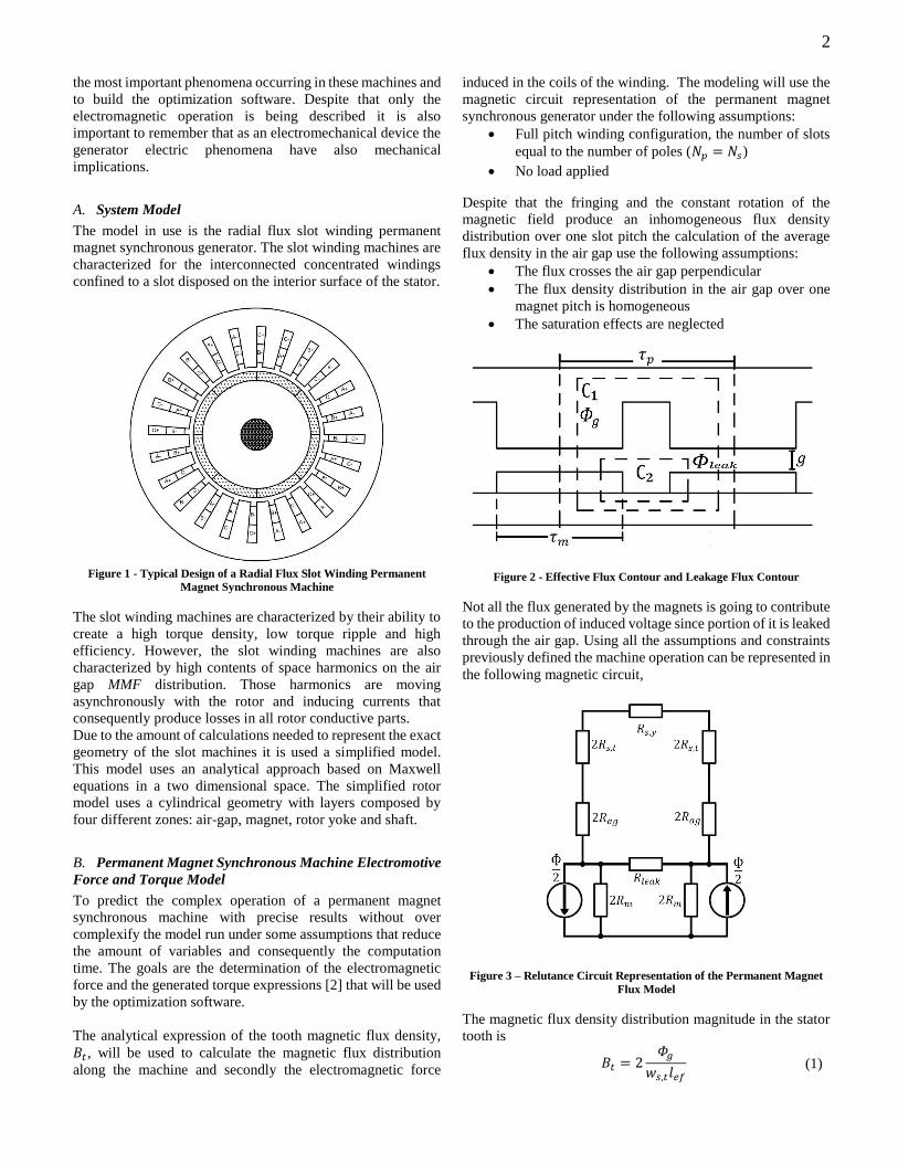
A. System Model
The model in use is the radial flux slot winding permanent
magnet synchronous generator. The slot winding machines are
characterized for the interconnected concentrated windings
confined to a slot disposed on the interior surface of the stator.
Figure 1 - Typical Design of a Radial Flux Slot Winding Permanent
Magnet Synchronous Machine
The slot winding machines are characterized by their ability to
create a high torque density, low torque ripple and high
efficiency. However, the slot winding machines are also
characterized by high contents of space harmonics on the air
gap MMF distribution. Those harmonics are moving
asynchronously with the rotor and inducing currents that
consequently produce losses in all rotor conductive parts.
Due to the amount of calculations needed to represent the exact
geometry of the slot machines it is used a simplified model.
This model uses an analytical approach based on Maxwell
equations in a two dimensional space. The simplified rotor
model uses a cylindrical geometry with layers composed by
four different zones: air-gap, magnet, rotor yoke and shaft.
B. Permanent Magnet Synchronous Machine Electromotive
Force and Torque Model
To predict the complex operation of a permanent magnet
synchronous machine with precise results without over
complexify the model run under some assumptions that reduce
the amount of variables and consequently the computation
time. The goals are the determination of the electromagnetic
force and the generated torque expressions [2] that will be used
by the optimization software.
The analytical expression of the tooth magnetic flux density,
𝐵𝑡 , will be used to calculate the magnetic flux distribution
along the machine and secondly the electromagnetic force
induced in the coils of the winding. The modeling will use the
magnetic circuit representation of the permanent magnet
synchronous generator under the following assumptions:
Full pitch winding configuration, the number of slots
equal to the number of poles (𝑁𝑝 = 𝑁𝑠)
No load applied
Despite that the fringing and the constant rotation of the
magnetic field produce an inhomogeneous flux density
distribution over one slot pitch the calculation of the average
flux density in the air gap use the following assumptions:
The flux crosses the air gap perpendicular
The flux density distribution in the air gap over one
magnet pitch is homogeneous
The saturation effects are neglected
Figure 2 - Effective Flux Contour and Leakage Flux Contour
Not all the flux generated by the magnets is going to contribute
to the production of induced voltage since portion of it is leaked
through the air gap. Using all the assumptions and constraints
previously defined the machine operation can be represented in
the following magnetic circuit,
Figure 3 – Relutance Circuit Representation of the Permanent Magnet
Flux Model
The magnetic flux density distribution magnitude in the stator
tooth is
𝐵𝑡 = 2𝛷𝑔
𝑤𝑠,𝑡𝑙𝑒𝑓 (1)

3
The continuous movement of the rotor will produce a change
on the magnetic field inducing a voltage in the stator coils. The
induced voltage EMF will be derived under the following
assumptions:
Balanced three phase system
The induce voltage is purely sinusoidal
𝐵𝑡(𝜃) = 𝐵𝑡 cos(𝜃) (2)
The flux linkage is given by
𝜆𝑡(𝑡) = 𝑁𝑛∬𝐵𝑡(𝜃) 𝑑𝑆𝑡𝑆
(3)
The induced voltage is
𝐸𝑡(𝑡) = −
𝑑𝜆𝑡(𝑡)
𝑑𝑡= −𝑁𝑛𝑙𝑒𝑓𝑟𝑟𝑜𝑡
1
𝑁𝑝
−2𝐵𝑡 cos(𝜃)
𝑑𝑡
(4)
The expression for the EMF induced in a single coil is given by
𝐸𝑡(𝑡) = 2𝜔𝑚𝑁𝑛𝑙𝑒𝑓𝑟𝑟𝑜𝑡𝐵𝑡sin (𝜔𝑒𝑡) (5)
The total EMF induced in a phase winding is the sum of the
voltages across the coils but because the winding assigned to
each phase is distributed in the stator slots the EMF induced on
different slots are not in phase and their sum is less than the
numerical sum therefore this effect can be translated as a factor,
the winding factor 𝑘𝑤, and the expression is given by
𝐸𝑝ℎ(𝑡) = 2𝑁𝑠𝑁𝑝ℎ
𝑘𝑤𝜔𝑚𝑁𝑛𝑙𝑒𝑓𝑟𝑟𝑜𝑡𝐵𝑡𝑠𝑖𝑛 (𝜔𝑒𝑡)
(6)
Using the previous expression it is possible to calculate the
applied output torque
𝑇 = 3√2𝑁𝑠𝑁𝑝ℎ
𝑘𝑤𝑁𝑛𝑙𝑒𝑓𝑟𝑟𝑜𝑡𝐵𝑡𝐼𝑝ℎ𝑐𝑜𝑠(𝜑) (7)
C. Winding Harmonics Model
The current on the coils of a generator originates a magnetic
interaction between the phase windings creating a magnetic
field that generates a magnetomotive force in the air gap. The
harmonics of the air gap MMF, also called space harmonics,
have undesirable effects on the generator operation.
Given the possible dispositions and arrangements of a winding
it is used a simplified procedure that allows a general method
for the calculation of the harmonics. The method [3] is based
on the conductor density distribution for each coil located on
the interior surface of the stator.
For a single coil the conductor density distribution is defined as
𝐶𝑛 =𝑁𝑛𝑏𝑠
(8)
, where 𝑏𝑠 is the stator slot mouth and 𝑁𝑛 is the number of turns
per coil. The conductor density distribution signal is defined by
the sense of the current flowing in the coil, as shown in Figure
4.
Each coil is defined by the following parameters:
Coil Axis 𝑥𝑛: middle point of the coil across the stator
coordinate system.
Coil Span 𝛼: distance between two coils centers.
Figure 4 – Planar Configuration of Stator and Rotor of a Fractional Slot
Generator
Using the complex Fourier analysis to calculate the conductor
density distribution for a series of coils the contributions of all
the coils have to be summed. The winding W consists of 𝑐
number of coils then the conductor density distribution is
𝐶𝑤(𝑥) = ∑ 𝐶𝑤 𝑒−𝑗2𝜈𝑑𝑥
∞
𝜈=−∞
(9)
, where v-th harmonic complex conductor distribution 𝐶𝑤 is
𝐶𝑤 =
= −2𝑗𝑁𝑛𝜋𝑑
(sin (
𝑘𝑏𝑠2)
𝑘𝑏𝑠2
)∑𝑠𝑖𝑛 (𝑘𝛼
2) 𝑒−𝑗𝑘𝑥𝑛
𝑐
𝑛=1
(10)
Using the conductor density distribution and the current in the
winding to calculate the air gap magnetic flux density for a
single coil:
𝐵𝑔(𝑥, 𝑡) =𝑗µ0𝑘𝑔
𝑖𝑝ℎ(𝑡)𝐶𝑛(𝑥)
=𝑗µ0𝑘𝑔
𝑖𝑝ℎ(𝑡) ∑ 𝐶𝑛(𝑥)𝑒−𝑗𝑘𝑥
∞
𝑘=−∞
(11)
,where 𝑔 is the air gap length.
Using the follow simplifications:
Number of coil turns: 𝑁𝑛
Coil Position at 𝑥𝑛
Narrow slot-mouth, 𝐾𝑏𝑠 ≈ 1
𝐵𝑔(𝑥, 𝑡) = 𝑖𝑝ℎ(𝑡)∑4µ0𝑘𝑔
𝑁𝑛𝜋𝑑
∞
𝑘=1
𝑠𝑖𝑛 (𝑘𝛼
2) cos (𝑘(𝑥
− 𝑥𝑛))
(12)

4
The air gap MMF is obtained by the relation with the magnetic
field strength:
𝐹𝑔(𝑥, 𝑡) = 𝑔𝐻𝑔(𝑥, 𝑡) =𝑔
µ0𝐵𝑔(𝑥, 𝑡)
(13)
For a group of coils connected in series the expression for the
air gap MMF is
𝐹𝑤(𝑥, 𝑡)
= 2𝑁𝑛𝑖𝑛(𝑡) ∑1
𝜈
∞
𝜈=−∞
(∑ 𝑠𝑖𝑛 (𝑘𝛼
2) cos (𝑘(𝑥
𝑐
𝑛=1
− 𝑥𝑛)))
(14)
The total magnitude of the air gap MMF harmonics is obtained
summing the expression for the total amount of coils connected
in series per phase
|𝐹��| = ( ∑ |𝐹𝑤 𝑟(𝑥, 𝑡)|
𝑛𝑢𝑚𝑏𝑒𝑟 𝑜𝑓 𝑝ℎ𝑎𝑠𝑒𝑠
𝑟=1
)
(15)
D. Rotor Losses Model
Permanent magnet machines with slot windings are usually the
solution used for direct drive applications because of their high
torque density, low torque ripple and high efficiency however
they also have a high content of space harmonics that mainly
cause losses. The model [4] in usage simplifies the geometry of
the materials composing the rotor to concentric cylindrical
layers and the expressions used to determine the losses are
Fourier series expansions of the Bessel functions.
The rotor losses are calculated using the four layers straight-
lined model neglecting the border effects in the machine along
𝐿𝑥, being the 𝐿𝑥 = 2𝜋𝑟𝑠𝑡𝑎𝑡,𝑖𝑛 where 𝑟𝑠𝑡𝑎𝑡,𝑖𝑛 is the stator inner
radius. Each one of the four regions are composed by the
following materials:
1. Region I: Air Gap
2. Region II: Magnet
3. Region III: Rotor Yoke
4. Region IV: Shaft
Each air gap MMF harmonic induces an alternate current in
the air gap region linear along the 𝑧 axis. That source is
assumed to be a linear current density with the following
expression,
𝐾𝑠 (𝑥) = 𝐾𝑠𝑒𝑗𝜋𝑥/𝜏𝜐 = 𝑘|𝐹��
𝑣=𝑣𝑛| 𝑒𝑗𝜋𝑥/𝜏𝜐
(16)
Figure 5 – Four Layer Rotor Regions
Applying the Maxwell´s equations using the magnetic vector
potential ��:
∇2�� − 𝑗𝜔𝜇0𝜎�� = 0
(17)
The magnetic vector potential �� can be expressed in terms of
two other functions ��(𝑥) and ��(𝑦) and due to the symmetry
the currents only have component on z :
��(𝑥, 𝑦) = ��(𝑥)��(𝑦)𝑢𝑧
(18)
In the air-gap region:
𝐴𝑧𝐼 (𝑥, 𝑦) = ��(𝑥)��(𝑦)
(19)
𝐴𝑧𝐼 (𝑥, 𝑦) = (𝑐1
��𝑒𝑗𝑐 𝐼𝑥 + 𝑐2
��𝑒−𝑗𝑐 𝐼𝑥) (𝑐3
��𝑒��𝐼𝑦
+ 𝑐4��𝑒−𝑐
𝐼𝑦)
(20)
In order to determine the coefficients it is necessary to fix
some boundary conditions. Along the surface at 𝑦 = 0, where
the linear current density follow:
𝐻𝑡𝐼 (𝑥, 𝑦 = 0) = 𝐾��(
𝑥)
(21)
1
𝜇𝐼��(𝑥)��𝐼(��3
𝐼 − ��4 𝐼) = ��𝑠𝑒
𝑗𝜋𝑥/𝜏𝜐
(22)
At the boundary between the regions I and II the following
equations are true,
{
𝐻𝑡
𝐼(𝑥, 𝑦𝑔) = 𝐻𝑡𝐼𝐼(𝑥, 𝑦𝑔) ⇔
1
𝜇𝐼𝜕��𝑧
𝐼 (𝑥, 𝑦)
𝜕𝑦|𝑦=𝑦𝑔
=1
𝜇𝐼𝐼𝜕��𝑧
𝐼𝐼(𝑥, 𝑦)
𝜕𝑦|𝑦=𝑦𝑔
��𝑛𝐼(𝑥, 𝑦𝑔) = ��𝑛
𝐼𝐼(𝑥, 𝑦𝑔) ⇔ −𝜕��𝑧
𝐼 (𝑥, 𝑦)
𝜕𝑥|𝑦=𝑦𝑔
= −𝜕��𝑧
𝐼𝐼(𝑥, 𝑦)
𝜕𝑥|𝑦=𝑦𝑔
(23)
,where 𝐻𝑡 is the tangential component of H and 𝐵𝑛 is the normal
component of B.
Note: The relations between the coefficients ��3𝐼𝐼 and ��4
𝐼𝐼are
obtained by these equations as for all the other regions.
Using the surface loss density function to calculate the losses
in each region,
𝑞𝑖 =𝜔2𝜎𝑖2
∫ �� 𝑖�� 𝑖∗𝑑𝑦𝑦𝑖
𝑦𝑖−1
(24)
The total rotor losses, in 𝑊, are given by

5
𝑃𝑟_𝑙𝑜𝑠𝑠 = 𝑟𝑟𝑜𝑡 ∗ 𝑙𝑒𝑓 ∗∑𝑞𝑖
4
𝑖=1
(25)
,where 𝑟𝑟𝑜𝑡 is the rotor radius and 𝑙𝑒𝑓 is the machine depth
length.
III. OPTIMIZATION SOFTWARE DEVELOPMENT
The best solution for a certain machine should be given by its
ability to fit the constraints predefined by the designer. This
challenge can be translated to mathematic language as an
optimization problem where the constraints identified by the
designer are the objective functions. Due to the problem
characteristics the optimization algorithm in use is the Genetic
Algorithm [5] and the objective functions for this generator are:
1. Maximization of Generated Torque
2. Minimization of Rotor Losses
3. Balanced Electrical Phase System
4. Minimization of Generator Volume
5. Minimization of Generator Material Costs
A. Optimization Problem Definition
For the given machine model was defined an individual
composed by two genome parts:
1. Winding Arrangement
2. Geometric Dimensions
Each one of them is defined separately although they are part
of a single genome and it is used by the Genetic Algorithm as
the unit that classifies each individual.
1. Winding Arrangement:
For a given number of slots, poles, phases and layers there is a
search space with a respective dimension. Due to the
characteristics of the slot winding it is possible to calculate the
total number of feasible arrangements using the equation that
gives the number of possible circular permutations with
repeated elements since:
the stator has no right or left end;
any slot can be the first one;
the repeated elements are the positive and negative
coil sides per phase.
For example:
Single Layer Winding with 12 slots:
randperm(12) = [ 1 6 2 4 3 5 ]
Table 1 – Coil Sides of a 12 Slot, 3 Phase, Single Layer Winding
Correspondence to Number Variables
Variables Coil Sides
1 +𝐴
2 +𝐵
3 +𝐶
4 −𝐴
5 −𝐵
6 −𝐶
2. Components Geometric Dimensions:
Not every part of the machine has its size defined because it
can be obtained from other parts sizes or is arbitrarily defined
due to its lower relevance on the model defined.
On the rotor the components defined are:
Rotor yoke length
Magnets: width and length
Air gap length
On the stator the component defined is:
Slot-mouth width
And additionally for the whole machine is also defined:
Machine length
The components geometric dimensions are defined using a
function that generates a random integer value.
3. Genome Configuration:
Using an example of 6 slots, 3 phases and 2 poles, single
layer an individual can have the following genome:
+
𝐴
−
𝐶
+
𝐵
−
𝐴
+
𝐶
−
𝐵
1
20
80
5
10
20
B. Objective Functions
Each one of the objective functions is a mathematical
translation of the constraints the designer puts on the generator:
1. [Maximization] Generated Torque:
𝑇 = 3√2
𝑁𝑠𝑁𝑝ℎ
𝑘𝑤𝑁𝑛𝑙𝑒𝑓𝑟𝑟𝑜𝑡𝐵𝑡𝐼𝑝ℎ𝑐𝑜𝑠(𝜑)
(26)
The objective is to maximize the main torque production.
2. [Minimization] Total Rotor Losses:
𝑟𝑙𝑜𝑠𝑠𝑒𝑠 =∑ ∑𝜔2𝜎𝑖2
∫ �� 𝑖�� 𝑖∗𝑑𝑦𝑦𝑖
𝑦𝑖−1
𝑛𝑢𝑚 𝑜𝑓 𝑟𝑒𝑔𝑖𝑜𝑛𝑠
𝑖=1
∞
𝑣=1
(27)
The objective is to minimize the losses on the rotor, increasing
the efficiency of the machine and decreasing the damage on the
materials.
3. Balanced Condition:

6
For the balanced condition is created a quantitative
classification that evaluate the magnetic balance created by the
winding arrangement.
Using the example of a 3-phase winding with conductor density
distribution of the winding per phase,
𝐶𝑛𝑝ℎ(𝑥) = ∑ 𝐶𝑛𝑝ℎ𝑣 𝑒−
𝑗2𝑣𝑑𝑥
∞
𝑣=−∞
(28)
Supplied by a balanced sinusoidal current of frequency ω.
The total stator surface current density is,
𝑗𝑠(𝑥, 𝑡) = 𝑖𝑠𝑎(𝑡)𝐶𝑛𝑎(𝑥) + 𝑖𝑠𝑏(𝑡)𝐶𝑛𝑏(𝑥)
+ 𝑖𝑠𝑐(𝑡)𝐶𝑛𝑐(𝑥) (29)
⇔ 𝑗𝑠(𝑥, 𝑡) = 𝑅𝑒 {√2𝐼�� [∑{(𝐶𝑛𝑎𝑣 + 𝑒−
2𝜋3𝑣𝐶𝑛𝑏
𝑣
∞
𝑣=1
+ 𝑒2𝜋3𝑣𝐶𝑛𝑐
𝑣 ) 𝑒− 𝑗2𝑣𝑑𝑥
+ (𝐶𝑛𝑎𝑣 ∗ + 𝑒−
2𝜋3𝑣𝐶𝑛𝑏
𝑣 ∗
+ 𝑒2𝜋3𝑣𝐶𝑛𝑏
𝑣 ∗) 𝑒𝑗2𝑣𝑑𝑥}] 𝑒𝑗𝜔𝑡}
From this expression it is possible to take two others that are
necessary conditions for the balanced condition:
{𝐶𝑛𝑎
𝑣 + 𝑒− 2𝜋3𝑣𝐶𝑛𝑏
𝑣 + 𝑒2𝜋3𝑣𝐶𝑛𝑐
𝑣 = 𝑅𝑒𝑎𝑙
𝐶𝑛𝑎𝑣 ∗ + 𝑒−
2𝜋3𝑣𝐶𝑛𝑏
𝑣 ∗ + 𝑒2𝜋3𝑣𝐶𝑛𝑏
𝑣 ∗ = 0
(30)
The objective is to minimize this function because unbalanced
machines may cause losses and damage on the machine. In this
model the value 0 for balanced condition is strictly necessary
to guarantee the generator operation mode without adding any
supplementary converters.
4. [Minimization] Volume:
𝑣𝑜𝑙 = 𝑙𝑒𝑓 ∗ 𝜋(𝑟𝑡𝑜𝑡𝑎𝑙)
2
(31)
, where 𝑟𝑡𝑜𝑡𝑎𝑙 is the dimension of the outter radius of the stator.
The objective is to minimize the volume of the machine and
consequently its weight.
5. [Minimization] Material Costs:
𝑝 = 𝑤𝑖𝑟𝑜𝑛 ∗ 𝑝𝑖𝑟𝑜𝑛 + 𝑤𝑝𝑚 ∗ 𝑝𝑝𝑚 + 𝑙𝑐𝑜𝑝𝑝𝑒𝑟
∗ 𝑝𝑐𝑜𝑝𝑝𝑒𝑟
(32)
, where 𝑤𝑖𝑟𝑜𝑛, 𝑤𝑝𝑚 and 𝑙𝑐𝑜𝑝𝑝𝑒𝑟 are the weight of iron and
permanent magnet of the machine and the length of the copper
wire respectively multiplied by the price per weight 𝑝𝑖𝑟𝑜𝑛
and 𝑝𝑝𝑚and price per length 𝑝𝑐𝑜𝑝𝑝𝑒𝑟.
IV. GENERATOR DESIGN AND TESTING
The goal is to design a permanent magnet synchronous
generator with electromechanical characteristics in the range
of:
- Rotation Speed: 100 𝑟𝑝𝑚
- Nominal Voltage: 550 𝑉
- Nominal Output Power: 20 𝑘𝑊
The electromechanic characteristics desired for the
synchronous machine, especially the rotation speed, provide
information to calculate the best combination of number of
poles, slots and phases for the generator. These characteristics
are used as a guide and every decision made takes in account
the solutions that could provide the best performance possible.
A. Generator Design Characteristics
Number of Phases:
The utilization of power electronic converters should be
avoided in a system that is desired to be direct drive. Since the
connection is made to the grid, three-phase system, then the
output of the generator should also be three-phase, therefore
𝑁𝑝ℎ = 3
Number of Poles and Slots:
The reference number of poles for a machine operating at
100 𝑟𝑝𝑚 is
𝑁𝑝 =120𝑓
𝑛=120.50
100= 60 𝑝𝑜𝑙𝑒𝑠
Despite the fundamental winding factor being lower when
using double layer when compared with the one layer also the
self and mutual inductances are lower, the EMF is more
sinusoidal, the harmonic content on MMF, the eddy current
losses and the overload torque capability are lower. Looking
for the best performance on a machine the advantages of using
the double layer winding are superior to the ones given by using
the one layer winding. The higher number of slots per pole per
phase, 𝑞, the more sinusoidal the magnetomotive force and
consequently the lower torque ripple and higher efficiency but
there isn´t a proportional relation between 𝑞 and the
fundamental winding factor. Because the winding assigned to
each phase is distributed in the stator slots the EMF induced on
the different slots are not in phase and their sum is less than the
numerical sum, the winding factor should be the biggest
possible to potentiate the EMF induced. The Figure 6 shows
how the fundamental winding factor depends on the number of
slots per pole per phase.
The fundamental winding factor is maximum in three points
that correspond to three different numbers of slots per pole per
phase. Taking in account that :
1. The number of coils/windings must be
multiple of the number of phases
2. The number of coils/windings is equal to the
number of slots.
Despite the fact that the fundamental winding factor has a
bigger value other combinations with higher number of slots
the combination chosen is 60 𝑝𝑜𝑙𝑒𝑠, 54 𝑠𝑙𝑜𝑡𝑠 because allows
the machine to have characteristics closer to the specified.

7
The number of slots chosen is
𝑁𝑠 = 54 𝑠𝑙𝑜𝑡𝑠
and the number of poles is
𝑁𝑝 = 60 𝑝𝑜𝑙𝑒𝑠
being the value for the synchronous speed, as previously
calculated, 𝑛 = 100 𝑟𝑝𝑚.
B. Software Run
The values of the machine structure previously calculated
will be used on the software to run tests to determine the best
possible solution for the machine design and construction.
Some features of the software input data can not be determined
by auxiliary calculations, such as material characteristics,
winding type remanent and flux density for the permanent
magnets, so they will be tested to find the solution that fits
better the machine requirements. At the end it will be presented
the final solution, with components sizes and winding
arrangement, that will be a guide for the machine design.
For the best solution the score of the objective functions:
- Generated Torque: 2 406 𝑁𝑚
- Rotor Losses: 320 𝑊
- Balanced Condition: 0 - Volume: 0,0823 𝑚3
- Material Costs: 2 881€
The geometric dimensions and the ending arrangement are:
- Air gap length: 1 𝑚𝑚
- Magnets: length: 29,2 𝑚𝑚
- Rotor yoke length: 112,0 𝑚𝑚
- Shaft length: 35 𝑚𝑚
- Magnet width: 12,3 𝑚𝑚
- Slot-mouth width: 10,1 𝑚𝑚
- Machine length (depth): 114,7 𝑚𝑚
- Winding Arrangement:
A
-
A
A
C
-
C
C
B
-
B
B
A -
A
A
C -
C
C
B -
B
B
A -
A
A
C -
C
C
B -
B
B -
A
A -
A -
C
C -
C -
B
B -
B -
A
A -
A -
C
C -
C -
B
B -
B -
A
A -
A -
C
C -
C -
B
B -
B
Also some other useful values were obtained from the
simulation:
- Number of coil turns: 84
- Power Factor: 0.8
These values will be used on the following sections as a
guideline to design the machine and test its electrical operation,
simulated in a finite element software as showed by the results
in Figure 7.
C. Simulation
Working in discrete time problem the main concern should be
the step time used because it affects the quality of the final
results. Knowing that the machine have repeated electrical
cycles in every rotation, the study will take advantage of that
repetitions and will only be focused on one electrical cycle. A
full electrical cycle for this machine corresponds to the
following mechanical interval angle,
𝜃 =2
𝑁𝑝 𝛾 =
2
60∗ 360 = 12° (33)
For a complete electrical cycle the rotor has to rotate 12°
(mechanical degrees). Taking this calculation in account the
step chosen was 0,1° and the total number of samples taken
from the simulation is 120.
Figure 6 - Fundamental Winding Factor vs Number of Slots per Pole per Phase [7]

8
The number of symmetries in the winding layout for a certain
number of poles and slots is given by the greatest common
divisor of those numbers
𝑠𝑦𝑚𝑚𝑒𝑡𝑟𝑖𝑐 𝑝𝑎𝑟𝑡𝑠 = 𝐺𝐶𝐷(60,54) = 6 (34)
Using the symmetries, the study of the electrical operation can
be reduced to a smaller part of the machine,
54 𝑠𝑙𝑜𝑡𝑠 ÷ 6 𝑠𝑦𝑚𝑚𝑒𝑡𝑟𝑖𝑐 𝑝𝑎𝑟𝑡𝑠= 9 𝑠𝑙𝑜𝑡𝑠/𝑠𝑦𝑚𝑚𝑒𝑡𝑟𝑖𝑐 𝑝𝑎𝑟𝑡
(35)
The simulation runs and calculates the magnetic flux density
along the entire machine showing the results as can be seen in
Figure 7. This distribution corresponds to the stationary study
when the rotor as an rotation angle of 0°.
Figure 7 - Magnetic Flux Density Norm Distribution
Using a parameterized curve crossing in each one of the
predetermined nine consecutive teeth of the machine, as
exemplified in one tooth on Figure 8, and calculating the radial
magnetic flux density across that line.
Figure 8 - Parameterized curve on the generator tooth
The results unit is Wb/m because the model is two dimensional
meaning that, for example, a measure of 2 Wb/m in a machine
with depth of 1 m gives a radial magnetic flux density of 2 Wb.
These results correspond to the magnetic flux simulated in two
dimensions and further calculations are required to obtain the
generator characteristics descried in the following steps:
Multiply each magnetic flux density per meter sample
by the generator depth giving the magnetic flux density
(𝛷𝐵)
Figure 9 - Magnetic flux vs rotor mechanical degree
Knowing the symmetries on the winding layout assign
each tooth of the machine with the correspondent
magnetic flux density
Calculate the derivative of the magnetic flux density of
each tooth (𝑑𝛷𝐵
𝑑𝑡)
Multiply the resultant value by the number of winding
turns, calculating the electromotive force (𝑒𝑚𝑓)
Assign each tooth with the respective winding phase
and direction (as in the winding layout arrangement)
Sum the electromotive force of teeth corresponding to
same winding phase (𝑒𝑚𝑓𝐴,𝑒𝑚𝑓
𝐵,𝑒𝑚𝑓
𝐶)
Figure 10 – Electromotive force of each phase vs rotor mechanical degree
9
Calculate the complex electromotive force of the
generator
𝑒𝑚𝑓𝑡𝑜𝑡 = 317 ∗ √3 ≈ 550 𝑉
(36)
The electromechanical specifications desired for the generator
are fulfilled:
- Rotation speed: 100 𝑟𝑝𝑚
The generator rotor rotation speed is given by relation
of the number of pole pairs and electric frequency from
the grid, the generator rotates at the specified speed.
- Nominal voltage: 550 𝑉
The nominal voltage is given by the peak value of the
complex electromotive force produced by the generator.
This chapter shows in detail that specific generator
characteristic and the value is around the nominal
voltage specified.
- Nominal output power: 20 𝑘𝑊 The nominal output power is calculated using the
nominal voltage
𝑃 = 𝑒𝑚𝑓𝑡𝑜𝑡 ∗ 𝐼𝑝ℎ ∗ 𝑝𝑓 = 550 ∗ 48 ∗ 0.8 = 21 120 𝑊
For simplification purposes the generator designed will further
on be designated as PLF PMSG20K.
As referred previously, the studies made by Costa (2003) [1] in
his master thesis determined the permanent magnet
synchronous generator Ginlong PMG-20K to be the cheapest
solution and also the one to guarantee a higher revenue. The
further comparisons between both generators should take in
account that the PLF PMSG20K is a designed generator with
reference values and the Ginlong PMG-20K is an already
commercialized machine.
The calculation of the copper losses are described and the
losses of magnetic parts in Strous (2010) [2] as following stated
𝑃𝑚𝑎𝑔 =𝜎𝑚𝜔𝑚
2 𝜋2𝑓2𝐵𝑚𝑎𝑥2
6𝑉𝑚
(37)
𝑃𝐶𝑢 = 𝑁𝑝ℎ𝑅𝑝ℎ𝐼𝑝ℎ2
(38)
Summing up all losses
𝑃𝑙𝑜𝑠𝑠𝑒𝑠 = 𝑃𝑟𝑜𝑡 + 𝑃𝐶𝑢 = 258,9 + 360,2 = 619,1 𝑊
(39)
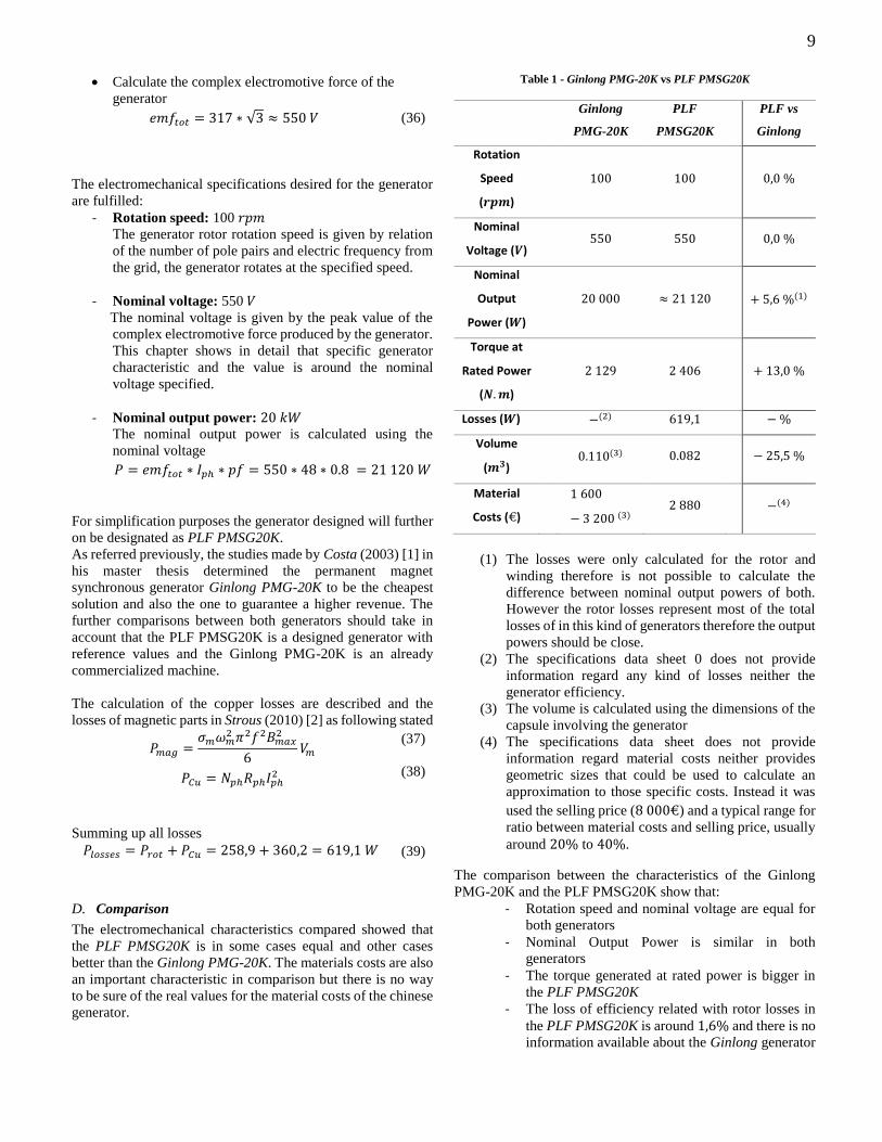
D. Comparison
The electromechanical characteristics compared showed that
the PLF PMSG20K is in some cases equal and other cases
better than the Ginlong PMG-20K. The materials costs are also
an important characteristic in comparison but there is no way
to be sure of the real values for the material costs of the chinese
generator.
Table 1 - Ginlong PMG-20K vs PLF PMSG20K
Ginlong
PMG-20K
PLF
PMSG20K
PLF vs
Ginlong
Rotation
Speed
(𝒓𝒑𝒎)
100 100
0,0 %
Nominal
Voltage (𝑽)
550 550
0,0 %
Nominal
Output
Power (𝑾)
20 000 ≈ 21 120
+ 5,6 %(1)
Torque at
Rated Power
(𝑵.𝒎)
2 129 2 406
+ 13,0 %
Losses (𝑾) −(2) 619,1 − %
Volume
(𝒎𝟑)
0.110(3) 0.082
− 25,5 %
Material
Costs (€)
1 600
− 3 200 (3) 2 880
−(4)
(1) The losses were only calculated for the rotor and
winding therefore is not possible to calculate the
difference between nominal output powers of both.
However the rotor losses represent most of the total
losses of in this kind of generators therefore the output
powers should be close.
(2) The specifications data sheet 0 does not provide
information regard any kind of losses neither the
generator efficiency.
(3) The volume is calculated using the dimensions of the
capsule involving the generator
(4) The specifications data sheet does not provide
information regard material costs neither provides
geometric sizes that could be used to calculate an
approximation to those specific costs. Instead it was
used the selling price (8 000€) and a typical range for
ratio between material costs and selling price, usually
around 20% to 40%.
The comparison between the characteristics of the Ginlong
PMG-20K and the PLF PMSG20K show that:
- Rotation speed and nominal voltage are equal for
both generators
- Nominal Output Power is similar in both
generators
- The torque generated at rated power is bigger in
the PLF PMSG20K
- The loss of efficiency related with rotor losses in
the PLF PMSG20K is around 1,6% and there is no
information available about the Ginlong generator

10
- The PLF PMSG20K is 25% smaller than the
Ginlong PMG-20K
- The material costs of the prototype version of the
PLF PMSG20K are in the range of the
commercialized version of the Ginlong PMG-20K.
V. CONCLUSION
The results obtained on the electromagnetic simulation are very
close to the ones obtained from the modeling. The results were
used to make further calculations that allowed a more reliable
comparison between the Ginlong PMG-20K and the PLF
PMSG20K. The generators have the same electromechanical
characteristics operating both at 100 𝑟𝑝𝑚, 550 𝑉 and 20 𝑘𝑊
making them competitors for the same market. Despite having
the same elctromechanical characteristics the PLF PMSG20K
generates more torque than the Ginlong generator and also have
rotor losses around 619 𝑊.Despite being possible to discuss
this value, it leads to a decrease of 2, 9% on the generator
efficiency which have a minor impact considering the main role
that the rotor losses play on the total losses in the generator.
Looking to the geometry of both generators it is possible to
verify that the PLF PMSG20K has a bigger radius but at the
same time a smaller depth. Further conclusions about the
internal geometry are not available because that is not
described in the Ginlong specifications data sheet. The
decrease on 25% of the volume is considerable and represents
a great chance of also reducing the generator weight.
Taking in account the positive results on the comparison made
with the Ginlong generator it is possible to verify that the
production of the PLF PMSG20K mainly relies on the material
costs. Despite not having conclusive values for the material
costs for the active parts of the Ginlong PMG-20K it is possible
to verify that both generators are in the same range of costs
even considering the prototype version of the generator
projected..
REFERENCES
[1] COSTA, A.(2013), Soluções de Geração para Aproveitamentos
Hidroelétricos das Correntes com Criação de Queda, Dissertation to obtain the Master Degree, University of Lisbon,
Instituto Superior Técnico, Lisbon, Portugal [2] STROUS, I. (2010), Design of a Permanent Magnet Radial Flux
Concentrated Coil Generator for a Range Extender Application,
Dissertation to obtain the Master Degree, Delft University of
Technology, Faculty of Electrical Engineering, Mathematics and Computer Science, Delft, Netherlands
[3] DELGADO, D. (2009), Automated AC Winding Design,
Disseration to obtain the mAster Degree, University of Manchester, Faculty of Engineering and Pgysical Sciences,
Manchester, United Kingdom
[4] FORNASIERO, E. (2010), Advanced Design of Direct Drive PM Machines, Dissertation to obtain the Doctor of Philosophy
Degree, University of Padova, Department of Electrical
Engineering, Padova, Italy
[5] MITCHELL, M. (1999), An Introduction to Genetic Algorithms,
Fifth edition, MIT Press, Massachusetts, United States of
America
[6] GINLONG, GL-PMG-20K Specification Sheet, [ONLINE]
Available at: http://www.ginlong.com/wind-turbine-pmg-pma-
permanent-magnet-generator-alternator-GL-PMG-20k.htm/. [Acessed September 2014]
[7] MEIER, F. (2008), Permanent Magnet Synchronous with
Non_Overlapping Concentrated Windings for Low-Speed direct Drive Applications, Dissertation to obtain the Doctor of
Philosophy degree, Royal Institute of Technology, Scholl of
Electrical Engineering, Stockholm, Sweden


![Selected TES Hydro Generators · Selected TES Hydro Generators. PROJECT LOCALITY TYPE QUANTITY [PC] OUTPUT [kVA/kW] SPEED [RPM] VOLTAGE [V] YEAR OF PRODUCTION Bulhary Synchronous](https://static.fdocuments.us/doc/165x107/5fd5a7ca6d38c230f01e1dd7/selected-tes-hydro-generators-selected-tes-hydro-generators-project-locality-type.jpg)