pak-blast-100 manual - GEMPLER'S · PDF filesetup instructionsbeforeoperatingthepak-blast...
36
08.05.04 FOR YOUR SAFETY, THE SAFETY OF FELLOW WORKERS AND EQUIPMENT LONGIVITY, READ, UNDERSTAND AND ABIDE BY ALL CAUTION NOTES, COMPLETE ALL INITIAL HOOKUP AND SETUP INSTRUCTIONS BEFORE OPERATING THE PAK-BLAST SPRAYER PAK-BLAST-100 MANUAL RECORD YOUR PAK-BLAST SERIAL NUMBER HERE INCLUDE IT IN ANY FACTORY CORRESPONDENCE
Transcript of pak-blast-100 manual - GEMPLER'S · PDF filesetup instructionsbeforeoperatingthepak-blast...

08.05.04
FOR YOUR SAFETY, THE SAFETY OF FELLOW WORKERS ANDEQUIPMENT LONGIVITY, READ, UNDERSTAND AND ABIDE BYALL CAUTION NOTES, COMPLETE ALL INITIAL HOOKUP ANDSETUP INSTRUCTIONS BEFORE OPERATING THE PAK-BLASTSPRAYER
PAK-BLAST-100MANUAL
RECORD YOUR PAK-BLAST SERIAL NUMBER HERE
INCLUDE IT IN ANY FACTORY CORRESPONDENCE
REAR'S MANUFACTURING COMPANY 1-800-547-8925 2140 PRAIRIE RD EUGENE, OR97402
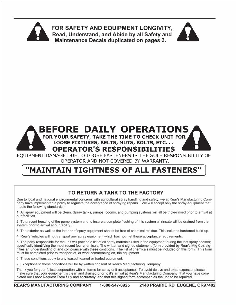
FOR SAFETY AND EQUIPMENT LONGIVITY,Read, Understand, and Abide by all Safety andMaintenance Decals duplicated on pages 3.
TO RETURN A TANK TO THE FACTORYDue to local and national environmental concerns with agricultural spray handling and safety, we at Rear's Manufacturing Com-pany have implemented a policy to regulate the acceptance of spray rig repairs. We will accept only the spray equipment thatmeets the following standards:1. All spray equipment will be clean. Spray tanks, pumps, booms, and pumping systems will all be triple-rinsed prior to arrival atour facilities.2. To prevent freezing of the pump system and to insure a complete flushing of this system all rinsate will be drained from thesystem prior to arrival at our facility.3. The exterior as well as the interior pf spray equipment should be free of chemical residue. This includes hardened build-up.4. Rear's vehicles will not transport any spray equipment which has not met these acceptance requirements.5. The party responsible for the unit will provide a list of all spray materials used in the equipment during the last spray season;specifically identifying the most recent four chemicals. The written and signed statement (form provided by Rear's Mfg Co), sig-nifies an understanding of and compliance with these contitions. The list of chemicals must be included on this form. This formmust be completed prior to transport of, or work commencing on, the equipment.6. These conditions apply to any leased, loaned or traded equipment.7. Exceptions to these conditions will be by written consent of Rear's Manufacturing Company.Thank you for your fullest cooperation with all terms for spray unit acceptance. To avoid delays and extra expense, pleasemake sure that your equipment is clean and drained prior to it's arrival at Rear's Manufacturing Company; that you have com-pleted our Labor Request Form fully and accurately; and that this signed form accompanies the unit to be repaired.
�
Read th�s manual completely before operat�ng: follow all safety �nstruct�ons.
Safety is a primary concern in the design and manufacture of our products. Unfortunately, our efforts to provide safe equipment can be wiped out by a single careless act of an operator.
In addition to the design and configuration of equipment, hazard control and ac-cident prevention are dependent upon the awareness, concern, prudence and proper training of personnel involved in the operation, transport, maintenance and storage of equipment.
It has been said, the best safety device is an informed, careful operator. We ask you to be that kind of an operator. It is the operator’s responsibility to read and understand all safety and operating instructions in the manual and to follow these. Accidents can be avoided.
Working with unfamiliar equipment can lead to careless injuries. Read this manual and the manual for your tractor before assembly or operation, to acquaint yourself with the machines. If this machine is used by any person other than the owner or is loaned or rented, it is the owner’s responsibility to make certain that the operator has instruction for the safe and proper use of the machinery and that the operator reads and understands the operator’s manuals.
Know your controls and how to stop the tractor, engine, and implement quickly in an emergency. Read this manual and the one provided with the tractor.
Train all new personnel and review instructions frequently with existing workers. A person who has not read and understood all operating and safety instructions is not qualified to operate the machine. An untrained operator exposes himself and bystanders to possible serious injury or death.
Do not allow children to operate this machine.
Sprayer Safety: Operator Tra�n�ng
READ THE OPERATOR’S MANUAL
READ THE OPERATOR’S MANUAL
READ THE OPERATOR’S MANUAL
Rears Manufactur�ng Company Inc. 800 547 8925
��
Never operate the tractor and implement until you read and completely understand this manual, the tractor operator’s manual, and each of the safety messages found on the safety decals on the tractor and the implement.
Personal protection equipment, including a hard hat, safety glasses, safety shoes, and gloves are recommended during assembly, installation, operation, adjustment, maintenance, repair, removal, or transport of this implement. Do not allow long hair, loose fitting clothing or jewellery to be around moving parts.
Tractors, with or without implements, can often be noisy enough to cause per-manent, partial hearing loss. We recommend that you wear hearing protection on a full-time basis if the noise in the operator’s position exceeds 80db. Long-term exposure to noise over 85db can cause severe hearing loss. Long-term exposure to noise over 90db may cause permanent, total hearing loss. NOTE: Hearing loss from loud noise (from tractors, chain saws, radio earphones) is cumulative over a lifetime without hope of natural recovery.
Operate the implement only with a tractor equipped with an approved Roll-Over-Protection-System (ROPS). Always wear your seat belt. Serious injury or even death could result from falling off a tractor– particularly during a turnover, when the operator could be pinned under the tractor.
Operate only in daylight or good artificial light.
Ensure the implement is properly mounted and in good operating condition.
Safety shielding and safety decals must be properly installed and in good condition.
Sprayer Safety: Preparat�on
���
Read th�s manual completely before operat�ng: follow all safety �nstruct�ons.
Implement operating power is supplied from the tractor’s PTO. Refer to your tractor manual for PTO engagement and disengagement instructions. Always operate the implement at its required PTO speed: either 540 or 1000 rpm. Know how to stop the tractor and implement quickly in case of an emergency. Keep children away at all times.
When engaging the PTO, the engine RPM should always be low. Once engaged, raise the PTO speed to the implement’s required operating speed: either 540 or 1000 rpm.
Check the tractor master shield over the PTO stub shaft. Make sure it is in good con-dition and fastened securely to the tractor. Purchase a new shield if the old shield is damaged or missing. A tractor salvage yard is a good source for older tractors.
Tractors without a live PTO need to be equipped with an over-running PTO clutch at-tachment, available through most farm equipment suppliers. NOTE: the addition of an over-running PTO clutch attachment will change the length of the PTO driveline required. Pay extra attention to the instructions on PTO driveline installation.
Sprayer Safety: Start�ng & Stopp�ng
Rears Manufactur�ng Company Inc. 800 547 8925
�v
Never provide agricultural chemicals to anyone unless that person has been properly trained or licensed.
Make certain the entire manufacturer’s label appears on the chemical container. Always follow the manufacturer’s instructions for storage, handling, and application.
Before a spraying operation is started the spray system should be rinsed and all nozzles, screens, and strainers cleaned. The best time to rinse and clean the spray system is at the END of daily operations, before storing the implement for the night. If cleaning is conscientiously included in day-end procedures, rinsate and the disposal of cleaning solution can easily be incorporated into your spray plan. Be careful if re-applying rinse solution to treated area: do not exceed the maximum rate for which the chemical is labeled.
Wear proper protective equipment when adding chemicals to the spray tank. The area where you are mixing must have adequate ventilation: powders, dust, and granuals can become airborn when adding to the spray tank; concentrated vapors can pose health or flammability hazards.
Mix only enough chemical for the particular job. Preventing chemical surplus is the best way to prevent a disposal problem.
Be aware of meteorological conditions and plan spray applications during opportune times. High winds and low humidity will increase drift and adversely affect your spray program.
Be alert for nozzle clogging and changes in nozzle patterns. Use strainers and nozzle screens appropriate for your water source and chemical use.
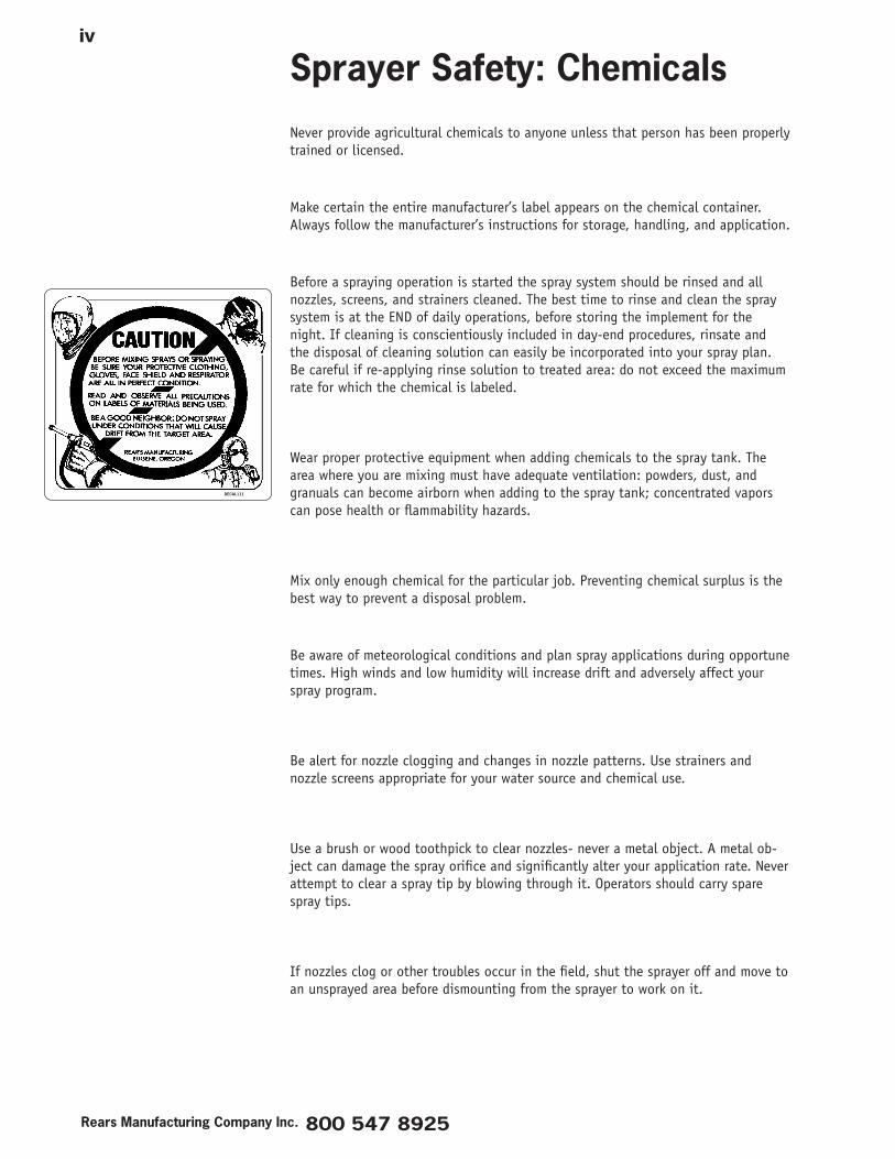
Use a brush or wood toothpick to clear nozzles- never a metal object. A metal ob-ject can damage the spray orifice and significantly alter your application rate. Never attempt to clear a spray tip by blowing through it. Operators should carry spare spray tips.
If nozzles clog or other troubles occur in the field, shut the sprayer off and move to an unsprayed area before dismounting from the sprayer to work on it.
Sprayer Safety: Chem�cals
�
Read this manual completely before operating: follow all safety instructions.
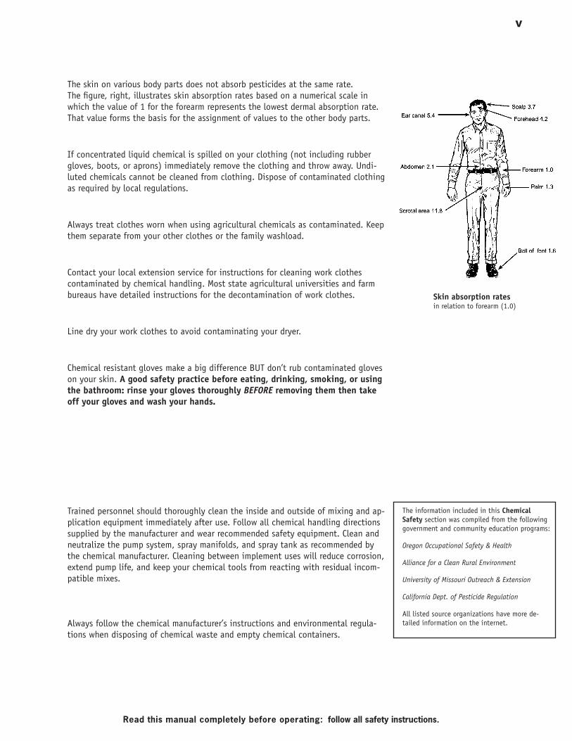
Skin absorption ratesin relation to forearm (1.0)
The skin on various body parts does not absorb pesticides at the same rate. The figure, right, illustrates skin absorption rates based on a numerical scale in which the value of 1 for the forearm represents the lowest dermal absorption rate. That value forms the basis for the assignment of values to the other body parts.
If concentrated liquid chemical is spilled on your clothing (not including rubber gloves, boots, or aprons) immediately remove the clothing and throw away. Undi-luted chemicals cannot be cleaned from clothing. Dispose of contaminated clothing as required by local regulations.
Always treat clothes worn when using agricultural chemicals as contaminated. Keep them separate from your other clothes or the family washload.
Contact your local extension service for instructions for cleaning work clothes contaminated by chemical handling. Most state agricultural universities and farm bureaus have detailed instructions for the decontamination of work clothes.
Line dry your work clothes to avoid contaminating your dryer.
Chemical resistant gloves make a big difference BUT don’t rub contaminated gloves on your skin. A good safety practice before eating, drinking, smoking, or using the bathroom: rinse your gloves thoroughly BEFORE removing them then take off your gloves and wash your hands.
Trained personnel should thoroughly clean the inside and outside of mixing and ap-plication equipment immediately after use. Follow all chemical handling directions supplied by the manufacturer and wear recommended safety equipment. Clean and neutralize the pump system, spray manifolds, and spray tank as recommended by the chemical manufacturer. Cleaning between implement uses will reduce corrosion, extend pump life, and keep your chemical tools from reacting with residual incom-patible mixes.
Always follow the chemical manufacturer’s instructions and environmental regula-tions when disposing of chemical waste and empty chemical containers.
The information included in this Chemical Safety section was compiled from the following government and community education programs:
Oregon Occupational Safety & Health
Alliance for a Clean Rural Environment
University of Missouri Outreach & Extension
California Dept. of Pesticide Regulation
All listed source organizations have more de-tailed information on the internet.
Rears Manufactur�ng Company Inc. 800 547 8925
v�
Install and secure all guards and shields before starting or operating.
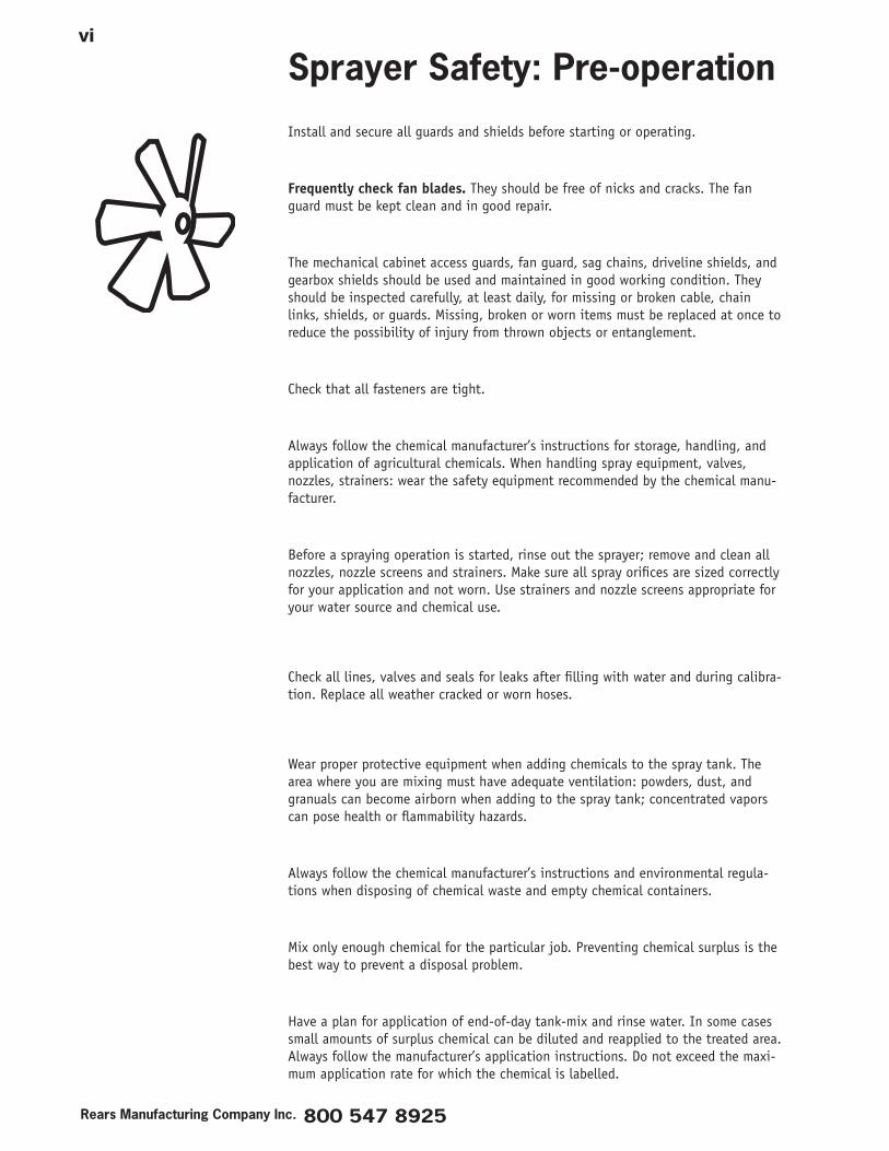
Frequently check fan blades. They should be free of nicks and cracks. The fan guard must be kept clean and in good repair.
The mechanical cabinet access guards, fan guard, sag chains, driveline shields, and gearbox shields should be used and maintained in good working condition. They should be inspected carefully, at least daily, for missing or broken cable, chain links, shields, or guards. Missing, broken or worn items must be replaced at once to reduce the possibility of injury from thrown objects or entanglement.
Check that all fasteners are tight.
Always follow the chemical manufacturer’s instructions for storage, handling, and application of agricultural chemicals. When handling spray equipment, valves, nozzles, strainers: wear the safety equipment recommended by the chemical manu-facturer.
Before a spraying operation is started, rinse out the sprayer; remove and clean all nozzles, nozzle screens and strainers. Make sure all spray orifices are sized correctly for your application and not worn. Use strainers and nozzle screens appropriate for your water source and chemical use.
Check all lines, valves and seals for leaks after filling with water and during calibra-tion. Replace all weather cracked or worn hoses.
Wear proper protective equipment when adding chemicals to the spray tank. The area where you are mixing must have adequate ventilation: powders, dust, and granuals can become airborn when adding to the spray tank; concentrated vapors can pose health or flammability hazards.
Always follow the chemical manufacturer’s instructions and environmental regula-tions when disposing of chemical waste and empty chemical containers.
Mix only enough chemical for the particular job. Preventing chemical surplus is the best way to prevent a disposal problem.
Have a plan for application of end-of-day tank-mix and rinse water. In some cases small amounts of surplus chemical can be diluted and reapplied to the treated area. Always follow the manufacturer’s application instructions. Do not exceed the maxi-mum application rate for which the chemical is labelled.
Sprayer Safety: Pre-operat�on
v��
Read th�s manual completely before operat�ng: follow all safety �nstruct�ons.
Be aware of the meteorological conditions and plan spray applications during op-portune times. High winds and low humidity will increase drift and adversely affect your spray program.
Avoid spraying near lakes, streams, pastures, population areas (houses, schools, playgrounds, hospitals) beehives or sensitive non-target crops. Always spray downwind from these sensitive areas and do not spray during adverse wind or low humidity conditions.
Follow your sprayer lubrication schedule.
Rears Manufactur�ng Company Inc. 800 547 8925
v���
The use of this equipment is subject to certain hazards which cannot be protected against by mechanical means or product design. All operators of this equipment must read and understand this entire manual, paying particular attention to safety and operating instructions, prior to use. If there is something in this manual you do not understand, ask your supervisor, dealer, or call the manufacturer.
Most accidents occur because of neglect or carelessness. Keep all helpers and bystanders at least several hundred feet away from the operating implement. Only properly trained people should operate this machine. Keep children away at all times.
The majority of accidents invlolve entanglement on a driveline, and operators being knocked off the tractor by low hanging limbs and run over. Accidents are most likely to occur with untrained operators or machines that are loaned or rented to someone who has not read the owner’s manual and is not familiar with the implement.
Always stop the tractor, set the brake, shut off the engine, remove the ignition key before dismounting the tractor. Never leave equipment unattended with the trac-tor running.
Never place any part of your body in the mechanical compartment with tractor engine running or before you are sure all motion has stopped. Stay clear of all moving parts.
Do not reach or place yourself under equipment until it is blocked securely.
Engage the PTO at low RPM and then bring the PTO speed up to operating speed.
Do not engage the implement PTO with the tractor and implement at right angles. Lessen strain on drivetrain by starting PTO when tractor and implement are in-line.
PAKBLAST AND PULBLAST UNITS: Never engage the fan at high speed.
POWERBLAST UNITS: When engaging the fan clutch the engine speed should be 1000RPM. Engaging the clutch at this speed, not greater or less, will ensure long clutch life.
Do not disengage the PTO while turning.
Take all possible precautions when leaving unit unattended: disengage PTO, set parking brake, stop engine, and remove key from ignition.
Sprayer Safety: Operat�on
�x
Read th�s manual completely before operat�ng: follow all safety �nstruct�ons.
Do not allow riders on the implement or tractor at any time. There is no safe place for any riders.
Disengage PTO and place transmission into neutral before attempting to start the engine.
Do not operate unless all personnel, livestock, and pets are out of your application area. Never direct discharge toward anyone. Keep children away at all times.
Inspect the entire machine periodically as indicated in the maintenance section of this manual. Look for loose fasteners, worn or broken parts, pinched hydraulic hoses, and leaky or loose fittings. Make sure all pins have cotter pins and washers. Serious injury may occur from not maintaining this machine in good working order. Install and secure all guards and shields before starting or operating.
Keep hands, feet, hair, and clothing away from all moving parts.
This implement is designed for use only on tractors with 540/1000 RPM power-take-off. DO NOT EXCEED YOUR IMPLEMENT’S RATED PTO SPEED.
If possible when applying chemical, work your way up-wind through your applica-tion area. By approaching the application such that drift goes into already treated rows the amount of chemical that will be blown onto the operator is reduced.
Be alert for nozzle clogging and changes in nozzle patterns. If nozzles clog or other troubles occur in the field, shut the sprayer off and move to an unsprayed area before dismounting from the tractor.
Rears Manufactur�ng Company Inc. 800 547 8925
x
Never try to unclog a nozzle by blowing through it. Always carry extra spray tips.
Never operate tractor and implement under trees with low hanging limbs: the op-erator can be knocked off the tractor and run-over.
Stay alert for holes, rocks and roots in the terrain and other hidden hazards. Keep away from drop-offs.
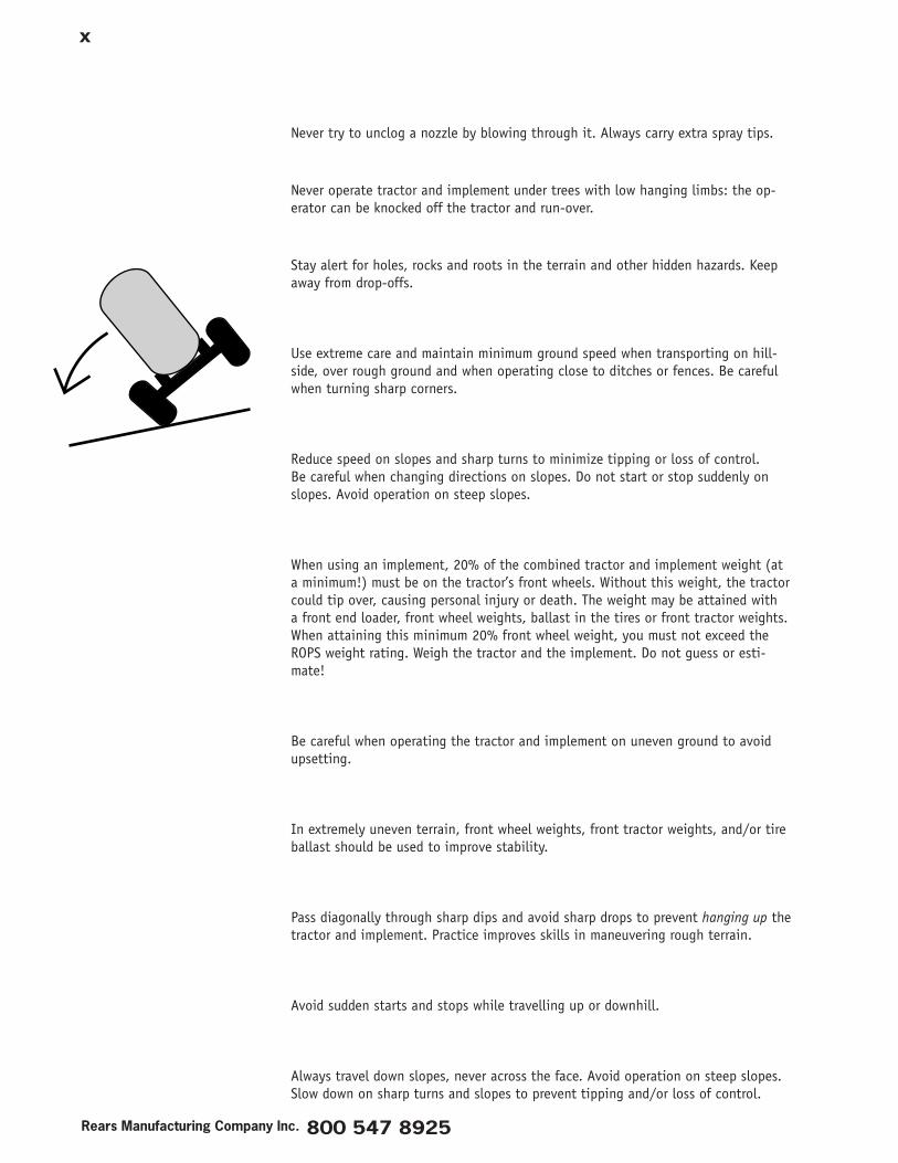
Use extreme care and maintain minimum ground speed when transporting on hill-side, over rough ground and when operating close to ditches or fences. Be careful when turning sharp corners.
Reduce speed on slopes and sharp turns to minimize tipping or loss of control. Be careful when changing directions on slopes. Do not start or stop suddenly on slopes. Avoid operation on steep slopes.
When using an implement, 20% of the combined tractor and implement weight (at a minimum!) must be on the tractor’s front wheels. Without this weight, the tractor could tip over, causing personal injury or death. The weight may be attained with a front end loader, front wheel weights, ballast in the tires or front tractor weights. When attaining this minimum 20% front wheel weight, you must not exceed the ROPS weight rating. Weigh the tractor and the implement. Do not guess or esti-mate!
Be careful when operating the tractor and implement on uneven ground to avoid upsetting.
In extremely uneven terrain, front wheel weights, front tractor weights, and/or tire ballast should be used to improve stability.
Pass diagonally through sharp dips and avoid sharp drops to prevent hanging up the tractor and implement. Practice improves skills in maneuvering rough terrain.
Avoid sudden starts and stops while travelling up or downhill.
Always travel down slopes, never across the face. Avoid operation on steep slopes. Slow down on sharp turns and slopes to prevent tipping and/or loss of control.
x�
Read th�s manual completely before operat�ng: follow all safety �nstruct�ons.
Failure to follow proper procedures when mounting a tire on a wheel or rim can produce an explosion which may result in serious injury or death.
Do not attempt to mount a tire unless you have the proper equipment and experi-ence to do the job.
Inflating or servicing tires can be dangerous. Whenever possible, trained personnel should be called to service and/or mount tires.
Always order and install tires and wheels with appropriate capacity to meet or exceed the anticipated weight to be placed on them.
Sprayer Safety: T�res
Rears Manufactur�ng Company Inc. 800 547 8925
x��
Good maintenance is your responsibility. Poor maintenance is an invitation to trouble.
Follow good shop practice. Keep service area clean and dry. Be sure electrical out-lets and tools are properly grounded. Use adequate light for the job at hand.
Make sure there is plenty of ventilation. Never operate gas/diesel engines in a closed building. The exhaust fumes may cause asphyxiation.
When handling spray equipment, pumps, valves, nozzles, strainers: wear the safety equipment recommended by the chemical manufacturer. Before working on the equipment, be certain the components are clean and neutralized as instructed by the chemical manufacturer.
Before working on this machine, disengage the PTO, shut off the engine, set the brakes and remove the key from the ignition.
Be certain all moving parts on tractor and implement have come to a complete stop before attempting to perform maintenance.
Never work under equipment unless it is blocked securely.
When performing any service or maintenance, always use personal protection de-vices such as eye, hand and hearing protection.
Trained personnel should throughly clean the inside and outside of equipment im-mediately after use. Follow all chemical handling directions supplied by the manu-facturer and wear recommended safety equipment. Clean and neutralize the pump system, spray manifolds, and spray tank as recommended by the chemical manu-facturer. Cleaning between implement uses will reduce corrosion, extend pump life, and keep your chemical tools from reacting with residual incompatible mixes.
Frequently check fan blades. They should be free of nicks or cracks and kept clean.
Periodically tighten all bolts, nuts and screws and check that all cotter pins are properly installed to insure unit is in a safe condition.
Sprayer Safety: Ma�ntenance
x���
Read th�s manual completely before operat�ng: follow all safety �nstruct�ons.
When completing a maintenance or service function, make sure all safety shields and devices are installed before placing the unit back in service.
Remove hydraulic pressure prior to doing any maintenance. Block the implement securely, disengage the PTO, and turn off the engine.
Never use your hands or any part of your body to locate a hydraulic leak. Use a piece of cardboard or wood to pass along the hydraulic line and determine the loca-tion of any leak. Wear protective gloves and glasses. Hydraulic fluid escaping under pressure can penetrate the skin. Openings in the skin and minor cuts are suscep-tible to infection from hydraulic fluid. If injured by escaping hydraulic fluid, see a doctor at once. Gangrene and death can result. Without immediate medical treat-ment, serious infection and reactions can occur.
When disconnecting hydraulic lines, shut off supply: relieve all hydraulic pressure.
Before pressurizing system, inspect all components. Make sure fittings are tight and lines are not worn, kinked or damaged.
After servicing, be sure all tools, parts and service equipment are removed.
Do not allow grease or oil build up on any deck or platform.
Never replace hex bolts with less than grade 5 bolts unless otherwise specified, i.e. shear bolts. Refer to bolt torque chart for head identification markings.
Where replacement parts are necessary for periodic maintenance and servicing, gen-uine factory replacement parts must be used to restore your equipment to original specifications. The manufacturer will not claim responsibility for use of unapproved parts and/or accessories and other damages as a result of their use.
If equipment has been altered in any way from the original design, the manufac-turer does not accept any liability for injury or warranty.
A fire extinguisher and first aid kit should be kept readily accessible while perform-ing maintenance on this or any equipment.
Rears Manufactur�ng Company Inc. 800 547 8925
x�v
Comply with state and local laws governing highway safety and movement of farm machinery on public roads.
The use of flashing amber lights is acceptable in most localities. However, some localities prohibit their use. Local laws should be checked for all highway lighting and marking requirements.
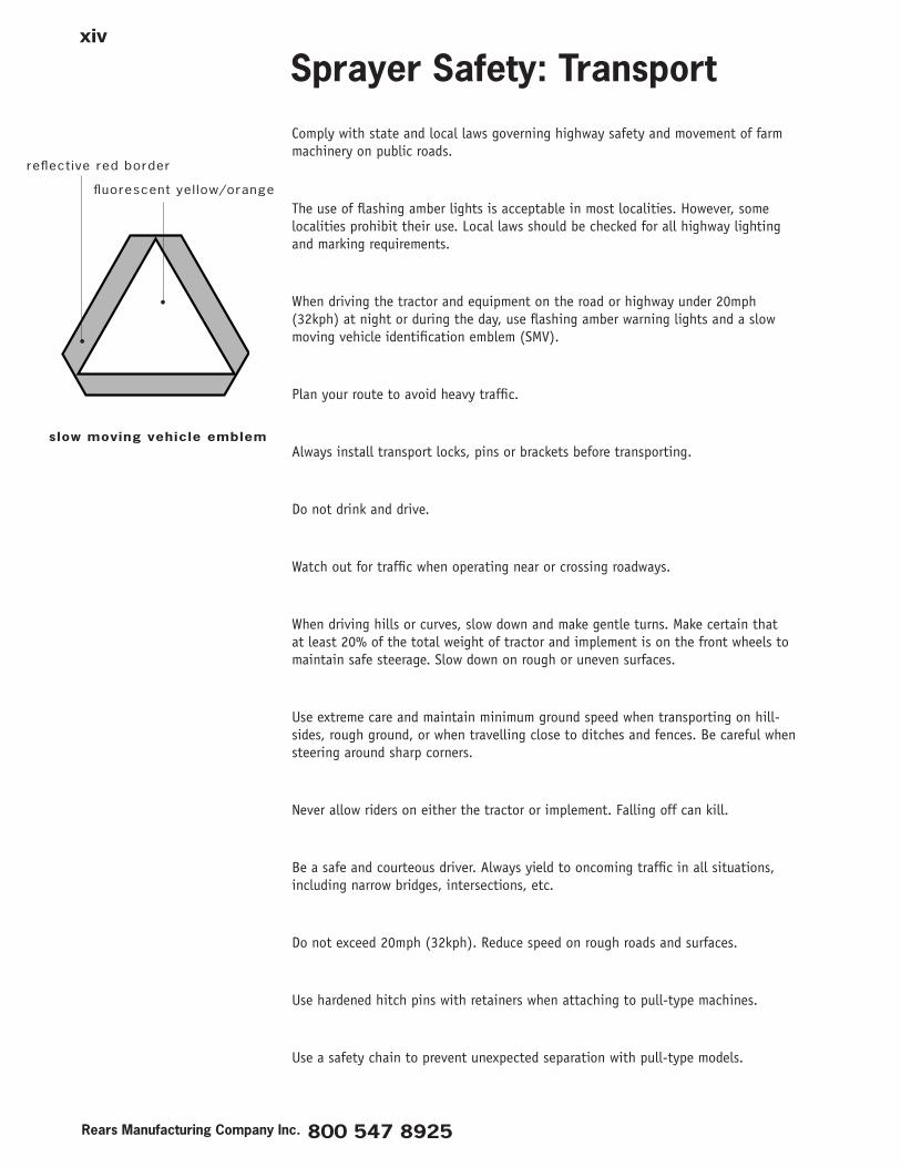
When driving the tractor and equipment on the road or highway under 20mph (32kph) at night or during the day, use flashing amber warning lights and a slow moving vehicle identification emblem (SMV).
Plan your route to avoid heavy traffic.
Always install transport locks, pins or brackets before transporting.
Do not drink and drive.
Watch out for traffic when operating near or crossing roadways.
When driving hills or curves, slow down and make gentle turns. Make certain that at least 20% of the total weight of tractor and implement is on the front wheels to maintain safe steerage. Slow down on rough or uneven surfaces.
Use extreme care and maintain minimum ground speed when transporting on hill-sides, rough ground, or when travelling close to ditches and fences. Be careful when steering around sharp corners.
Never allow riders on either the tractor or implement. Falling off can kill.
Be a safe and courteous driver. Always yield to oncoming traffic in all situations, including narrow bridges, intersections, etc.
Do not exceed 20mph (32kph). Reduce speed on rough roads and surfaces.
Use hardened hitch pins with retainers when attaching to pull-type machines.
Use a safety chain to prevent unexpected separation with pull-type models.
Sprayer Safety: Transport
reflective red border
fluorescent yel low/orange
slow mov�ng veh�cle emblem
xv
Read th�s manual completely before operat�ng: follow all safety �nstruct�ons.
With pull-type units, never unhitch the implement without using the tongue jack. The tongue is very heavy. Attempting to lift the tongue without using the tongue jack could cause personal injury. Overloading the jack can cause failure with pos-sible serious injury or even death.
Trained personnel should thoroughly clean the inside and outside of equipment im-mediately after use. Personnel should wear protective equipment as recommended by the chemical manufacturer.
Before storing the sprayer for an extended period flush the plumbing with a light weight oil mixture with water (approx. 1 gallon of oil for 40 gallons of water). When draining spray manifolds, remove the check-valve cap from the top-most nozzle assembly to release vacuum. Flush pump and system with RV antifreeze solu-tion and leave solution in the pump for storage. Remove nozzle tips and screens and store in a can of light oil to prevent corrosion. Plug the nozzle openings with blanks.
Lubricate as instructed in the maintenance schedule.
Inspect all lines, hoses, valves before storing. Damage to pump and plumbing should be repaired before storage. Make a list of replacement parts needed and order early. For the best performance next season, have your dealer service the machine prior to storage.
Re-paint all parts where the paint has been worn.
Store the implement away from activity.
Do not park equipment where it will be exposed to livestock. Damage to equipment or injury to livestock could result.
Do not permit children to play on or around the implement.
Make sure the parked unit is on a hard, level surface with all safety devices in place and in good working condition. Block up frame to lighten load on tires. Do not deflate tires. Cover tires if exposed to sunlight, grease, or oil.
Sprayer Safety: Storage
Rears Manufactur�ng Company Inc. 800 547 8925
xv�
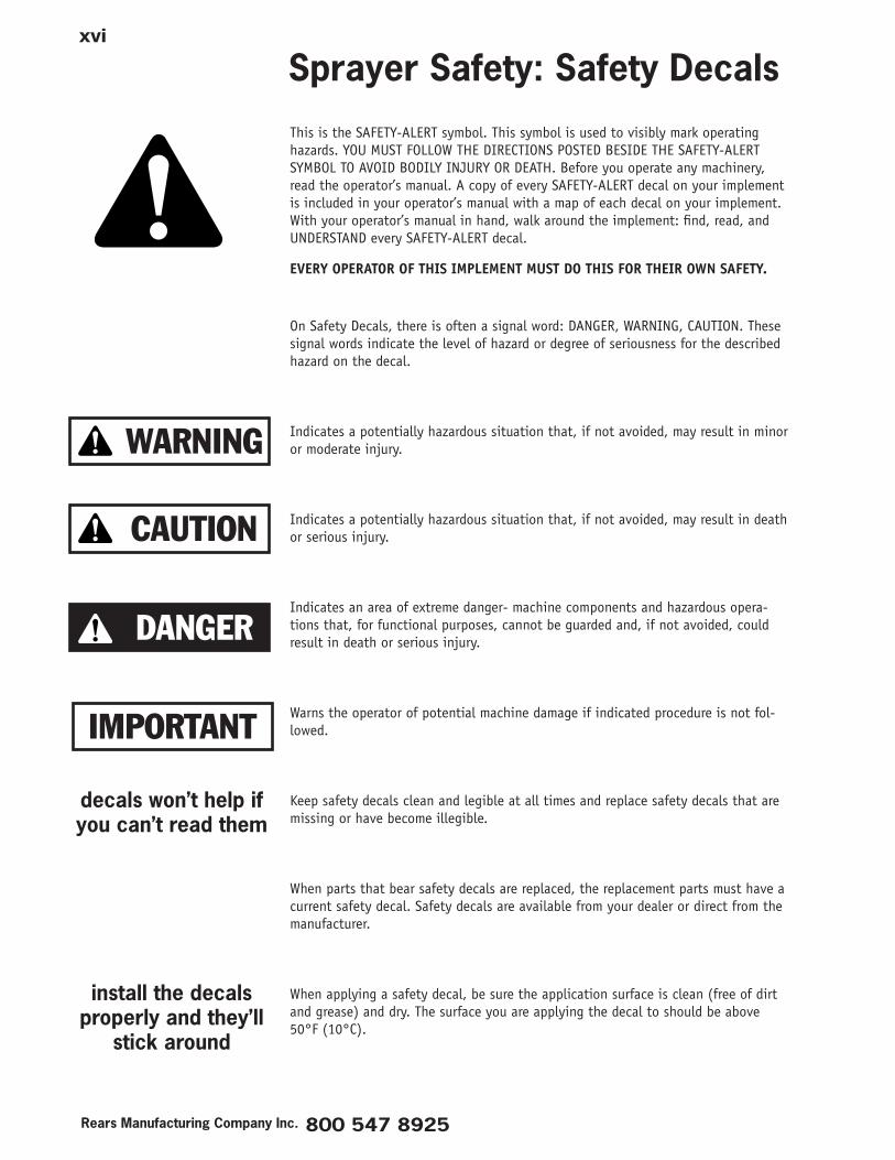
This is the SAFETY-ALERT symbol. This symbol is used to visibly mark operating hazards. YOU MUST FOLLOW THE DIRECTIONS POSTED BESIDE THE SAFETY-ALERT SYMBOL TO AVOID BODILY INJURY OR DEATH. Before you operate any machinery, read the operator’s manual. A copy of every SAFETY-ALERT decal on your implement is included in your operator’s manual with a map of each decal on your implement. With your operator’s manual in hand, walk around the implement: find, read, and UNDERSTAND every SAFETY-ALERT decal.
EVERY OPERATOR OF THIS IMPLEMENT MUST DO THIS FOR THEIR OWN SAFETY.
On Safety Decals, there is often a signal word: DANGER, WARNING, CAUTION. These signal words indicate the level of hazard or degree of seriousness for the described hazard on the decal.
Indicates a potentially hazardous situation that, if not avoided, may result in minor or moderate injury.
Indicates a potentially hazardous situation that, if not avoided, may result in death or serious injury.
Indicates an area of extreme danger- machine components and hazardous opera-tions that, for functional purposes, cannot be guarded and, if not avoided, could result in death or serious injury.
Warns the operator of potential machine damage if indicated procedure is not fol-lowed.
Keep safety decals clean and legible at all times and replace safety decals that are missing or have become illegible.
When parts that bear safety decals are replaced, the replacement parts must have a current safety decal. Safety decals are available from your dealer or direct from the manufacturer.
When applying a safety decal, be sure the application surface is clean (free of dirt and grease) and dry. The surface you are applying the decal to should be above 50°F (10°C).
Sprayer Safety: Safety Decals
WARNING
CAUTION
DANGER
IMPORTANT
decals won’t help �fyou can’t read them
�nstall the decalsproperly and they’ll
st�ck around

REAR'S MANUFACTURING COMPANY 1-800-547-8925 2140 PRAIRIE ROAD EUGENE, OR97402
PAK-BLAST-100 3
REAR'S MANUFACTURING COMPANY 1-800-547-8925 2140 PRAIRIE RD EUGENE, OR97402
4 PAK-BLAST-100
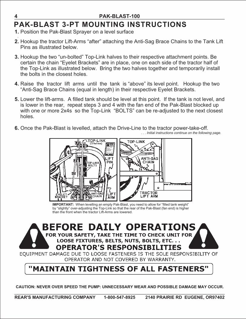
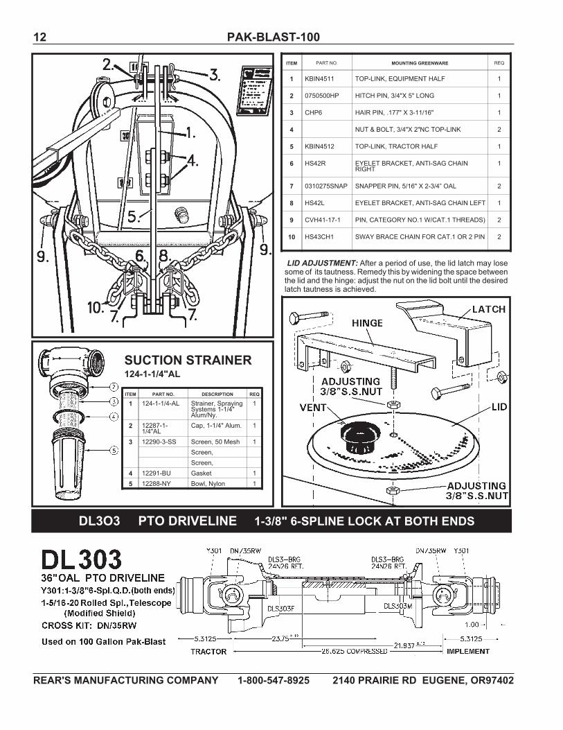
1. Position the Pak-Blast Sprayer on a level surface.2. Hookup the tractor Lift-Arms “after” attaching the Anti-Sag Brace Chains to the Tank LiftPins as illustrated below.
3. Hookup the two “un-bolted” Top-Link halves to their respective attachment points. Becertain the chain “Eyelet Brackets” are in place, one on each side of the tractor half ofthe Top-Link as illustrated below. Bring the two halves together and temporarily installthe bolts in the closest holes.
4. Raise the tractor lift arms until the tank is “above” its level point. Hookup the two“Anti-Sag Brace Chains (equal in length) in their respective Eyelet Brackets.
5. Lower the lift-arms. A filled tank should be level at this point. If the tank is not level, andis lower in the rear, repeat steps 3 and 4 with the fan end of the Pak-Blast blocked upwith one or more 2x4s so the Top-Link “BOLTS” can be re-adjusted to the next closestholes.
6. Once the Pak-Blast is levelled, attach the Drive-Line to the tractor power-take-off.
IMPORTANT: When levelling an empty Pak-Blast, you need to allow for “filled tank weight”by “slightly” over-adjusting the Top-Link so that the rear of the Pak-Blast (fan end) is higherthan the front when the tractor Lift-Arms are lowered.
. . . Initial instructions continue on the following page.
CAUTION: NEVER OVER SPEED THE PUMP: UNNECESSARY WEAR AND POSSIBLE DAMAGE MAY OCCUR.
PAK-BLAST 3-PT MOUNTING INSTRUCTIONS
REAR'S MANUFACTURING COMPANY 1-800-547-8925 2140 PRAIRIE ROAD EUGENE, OR97402
PAK-BLAST-100 5
INITIAL OPERATIONS/PRECAUTIONS(PLEASE READ AND UNDERSTAND THOROUGHLY - BEFORE BEGINNING OPERATIONS)
LUBRICATION:Use TEXACONO.2 CHASSISGREASE or equivalent; apply two (2) shots of grease to each pto u-joint; agitator bear-ings utilize impregnated bronze bushings which require minimal attention, apply grease lightly, stopping when resis-tance is felt... “NEVER OVER GREASE,” excess will enter tank.
BEFORE OPERATING PUMP:1. Fill tank with water above pump level (Open Suction Valve).2. Check/Maintain Pump Oil Level (keep above halfway mark on transparent plastic fill tube).3. Check All Suction Lines For Tightness.4. Check Strainer(s), keep clean and tight.5. Clear Air From Pump and system Lines: fully open relief valve - open discharge to tank and run for several minutesat zero pressure circulating liquid.
TO OBTAIN PUMP PULSATION CONTROL:1. Shutdown pump.2. Relieve system pressure.3. Add air to airdome (40 to 50 psi).4. Start-up pump, attain working pressure.5. Bleed off air “in very small amounts” until pulsation has ceased or is reduced to its minimum.NOTE: If “minimum” pulsation is passed and pulsation begins to “increase” repeat steps 1 through 5. Adjust PressureRegulator to comply with your specific needs.
KEEP SUCTION STRAINER CLEAN:Check and clean Suction Strainer often, ideally between refills, especially when using less than clean ditch or well wa-ter and some harsh chemicals.IMPORTANT: The sole purpose of the suction valve is to shut-off flow if suction strainer requires cleaning while tankhas liquid in it. NEVERCLOSESUCTIONVALVEwhile system is running: pump damage can occur. Operatingwith aClogged Strainer will have Equal Results.
SET-UP handgun or spray boom attachment to be used.
ENGAGE tractor pto/or start gas engine drive. Water flow should show through clear suction hose to pump. Somepressure should show on gauge.
RELIEF VALVE:To ensure proper priming of pump and prevent possible water hammer action that could cause glycerin pressuregauge damage, fully open Relief Valve.
SET A WORKING PRESSURE:Toaccurately set a prescribedworking pressure, handgun/spray boomhas to be on and spraying: Turn the handgun orspray boom on and adjust the relief valve until your working pressure is attained. When handgun/spray boom is turnedoff, the pressure will show an increase at pressure gauge.
AFTER 1 HOUR OF INITIAL OPERATION:Recheck tightness of all nuts and bolts, set-screws, belts, etc., as previously described. It is good practice tomake thischeck each time the machine is being serviced.
CAUTION: NEVER OVER SPEED THE PUMP “UNNECESSARY WEAR AND POSSIBLEDAMAGE MAY OCCUR.” OPERATE AT OR BELOW TRACTOR PTO “540 RPM.”
REAR'S MANUFACTURING COMPANY 1-800-547-8925 2140 PRAIRIE RD EUGENE, OR97402
6 PAK-BLAST-100
SETUP A PUMP AND SYSTEM MAINTENANCE ROUTINEPREVENT DAMAGING CHEMICAL BUILDUP:AFTER DAILY USE, fully open Relief Valve to discharge back to tank. Engage pump and run two or three minutes atZERO pressure on gauge, circulating clean water through the pump several minutes to reduce harmful chemicalbuildup. Proper maintenance will greatly extend the life of hoses, seals, screens, nozzles, pump valves, and dia-phragms, especially when harsh chemical are used. Check and Clean Suction Strainer Screen.
CHECK HOSE LINES & FITTINGS:Check all hose lines and fittings for no-leak tightness.
PUMP:MAINTAIN PUMP OIL LEVEL: Keep pump oil level above half-way mark on filler tube. When low, add a good gradenon-detergent motor oil (30wt).
CHANGING PUMP OIL:Pump oil change should occur every 200 hours or at end of season, whichever comes first. When changing the oil, in-spect the diaphragms and valves: you are looking for diaphragm swelling or stretching and wear check marks, alsovalve seat wear and valve spring fatigue. Refill pump with a good grade non-detergent motor oil (30wt). Rotate theshaft while filling to ensure complete air evacuation from pump body. This oil change andmaintenance check ensuresgreater trouble free operations throughout each season.
SEASONAL STORAGE & WINTERIZING (WARNING: Do Not use Diesel Oil in this process):1. Fully flush system, recirculating “clean” water.2. Fully flush again, recirculating a sufficient ANTI-FREEZE solution.3. Shutdown, leaving sufficient ANTI-FREEZE solution in pump, tank, and throughout system.NOTE: The ANTI-FREEZE solution is determined regarding winter temperatures in your area.
CAUTION: NEVER OVER SPEED THE PUMP “UNNECESSARY WEAR AND POSSIBLEDAMAGE MAY OCCUR.” OPERATE AT OR BELOW TRACTOR PTO “540 RPM.”
REAR'S MANUFACTURING COMPANY 1-800-547-8925 2140 PRAIRIE ROAD EUGENE, OR97402
PAK-BLAST-100 7
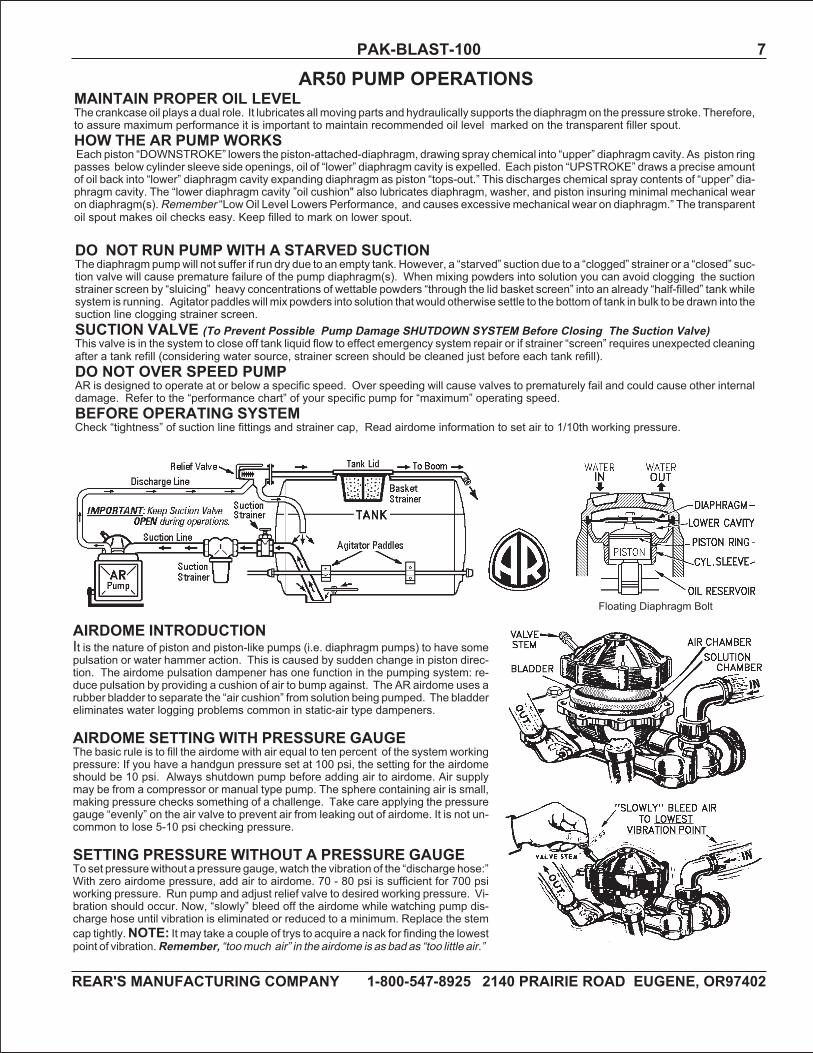
AIRDOME INTRODUCTIONIt is the nature of piston and piston-like pumps (i.e. diaphragm pumps) to have somepulsation or water hammer action. This is caused by sudden change in piston direc-tion. The airdome pulsation dampener has one function in the pumping system: re-duce pulsation by providing a cushion of air to bump against. The AR airdome uses arubber bladder to separate the “air cushion” from solution being pumped. The bladdereliminates water logging problems common in static-air type dampeners.
AIRDOME SETTING WITH PRESSURE GAUGEThe basic rule is to fill the airdome with air equal to ten percent of the system workingpressure: If you have a handgun pressure set at 100 psi, the setting for the airdomeshould be 10 psi. Always shutdown pump before adding air to airdome. Air supplymay be from a compressor or manual type pump. The sphere containing air is small,making pressure checks something of a challenge. Take care applying the pressuregauge “evenly” on the air valve to prevent air from leaking out of airdome. It is not un-common to lose 5-10 psi checking pressure.
SETTING PRESSURE WITHOUT A PRESSURE GAUGETo set pressurewithout a pressure gauge, watch the vibration of the “discharge hose:”With zero airdome pressure, add air to airdome. 70 - 80 psi is sufficient for 700 psiworking pressure. Run pump and adjust relief valve to desired working pressure. Vi-bration should occur. Now, “slowly” bleed off the airdome while watching pump dis-charge hose until vibration is eliminated or reduced to a minimum. Replace the stemcap tightly.NOTE: It may take a couple of trys to acquire a nack for finding the lowestpoint of vibration.Remember, “toomuch air” in the airdome is as bad as “too little air.”
AR50 PUMP OPERATIONSMAINTAIN PROPER OIL LEVELThe crankcase oil plays a dual role. It lubricates all moving parts and hydraulically supports the diaphragmon the pressure stroke. Therefore,to assure maximum performance it is important to maintain recommended oil level marked on the transparent filler spout.HOW THE AR PUMPWORKSEach piston “DOWNSTROKE” lowers the piston-attached-diaphragm, drawing spray chemical into “upper” diaphragm cavity. As piston ringpasses below cylinder sleeve side openings, oil of “lower” diaphragm cavity is expelled. Each piston “UPSTROKE” draws a precise amountof oil back into “lower” diaphragm cavity expanding diaphragm as piston “tops-out.” This discharges chemical spray contents of “upper” dia-phragm cavity. The “lower diaphragm cavity ”oil cushion" also lubricates diaphragm, washer, and piston insuring minimal mechanical wearon diaphragm(s). Remember “LowOil Level Lowers Performance, and causes excessivemechanical wear on diaphragm.” The transparentoil spout makes oil checks easy. Keep filled to mark on lower spout.
DO NOT RUN PUMPWITH A STARVED SUCTIONThe diaphragmpumpwill not suffer if run dry due to an empty tank. However, a “starved” suction due to a “clogged” strainer or a “closed” suc-tion valve will cause premature failure of the pump diaphragm(s). When mixing powders into solution you can avoid clogging the suctionstrainer screen by “sluicing” heavy concentrations of wettable powders “through the lid basket screen” into an already “half-filled” tank whilesystem is running. Agitator paddleswill mix powders into solution that would otherwise settle to the bottomof tank in bulk to be drawn into thesuction line clogging strainer screen.SUCTION VALVE (To Prevent Possible Pump Damage SHUTDOWN SYSTEM Before Closing The Suction Valve)This valve is in the system to close off tank liquid flow to effect emergency system repair or if strainer “screen” requires unexpected cleaningafter a tank refill (considering water source, strainer screen should be cleaned just before each tank refill).DO NOT OVER SPEED PUMPAR is designed to operate at or below a specific speed. Over speeding will cause valves to prematurely fail and could cause other internaldamage. Refer to the “performance chart” of your specific pump for “maximum” operating speed.BEFORE OPERATING SYSTEMCheck “tightness” of suction line fittings and strainer cap, Read airdome information to set air to 1/10th working pressure.
Floating Diaphragm Bolt
REAR'S MANUFACTURING COMPANY 1-800-547-8925 2140 PRAIRIE RD EUGENE, OR97402
8 PAK-BLAST-100
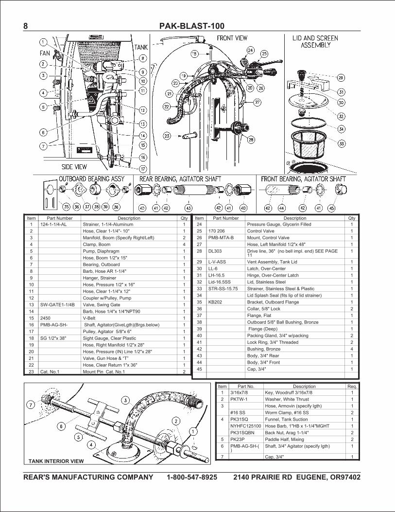
Item Part Number Description Qty1 124-1-1/4-AL Strainer, 1-1/4-Aluminum 12 Hose, Clear 1-1/4"- 10" 13 Manifold, Boom (Specify Right/Left) 24 Clamp, Boom 45 Pump, Diaphragm 16 Hose, Boom 1/2"x 15" 17 Bearing, Outboard 18 Barb, Hose AR 1-1/4" 19 Hanger, Strainer 110 Hose, Pressure 1/2" x 16" 111 Hose, Clear 1-1/4"x 12" 112 Coupler w/Pulley, Pump 113 SW-GATE1-1/4B Valve, Swing Gate 114 Barb, Hose 1/4"x 1/4"NPT90 115 2450 V-Belt 116 PMB-AG-SH- Shaft, Agitator(GiveLgth)(Brgs.below) 117 Pulley, Agitator 5/8"x 6" 118 SG 1/2"x 38" Sight Gauge, Clear Plastic 119 Hose, Right Manifold 1/2"x 28" 120 Hose, Pressure (IN) Line 1/2"x 28" 121 Valve, Gun Hose & “T” 122 Hose, Clear Return 1"x 36" 123 Cat. No.1 Mount Pin Cat. No.1 2
Item Part Number Description Qty24 Pressure Gauge, Glycerin Filled 125 170 206 Control Valve 126 PMB-MTA-B Mount, Control Valve 127 Hose, Left Manifold 1/2"x 48" 128 DL303 Drive line, 36" (no bell impl. end) SEE PAGE
111
29 L-V-ASS Vent Assembly, Tank Lid 130 LL-6 Latch, Over-Center 131 LH-16.5 Hinge, Over-Center Latch 132 Lid-16.5SS Lid, Stainless Steel 133 STR-SS-15.75 Strainer, Stainless Steel & Plastic 134 Lid Splash Seal (fits lip of lid strainer) 135 KB202 Bracket, Outboard Flange 136 Collar, 5/8" Lock 237 Flange, Flat 138 Outboard 5/8" Ball Bushing, Bronze 139 Flange (Deep) 140 Packing Gland, 3/4" w/packing 241 Lock Ring, 3/4" Threaded 242 Bushing, Bronze 443 Body, 3/4" Rear 144 Body, 3/4" Front 145 Cap, 3/4" 1
TANK INTERIOR VIEW
Item Part No. Description Req.1 3/16x7/8 Key, Woodruff 3/16x7/8 12 PKTW-1 Washer, White Thrust 13 Hose, Armovin (specify lgth) 1
#16 SS Worm Clamp, #16 SS 24 PK31SQ Funnel, Tank Suction 1
NYHFC125100 Hose Barb, 1"HB x 1-1/4"MGHT 1PK31SQBN Back Nut, Arag 1-1/4" 2
5 PK23P Paddle Half, Mixing 26 PMB-AG-SH-(
)Shaft, 3/4" Agitator (specify lgth) 1
7 Cap, 3/4" 1
REAR'S MANUFACTURING COMPANY 1-800-547-8925 2140 PRAIRIE ROAD EUGENE, OR97402
PAK-BLAST-100 9
To expedite an order and assure receiving correct part(s), include your Pak-Blast Serial Number, fan style, and fan size
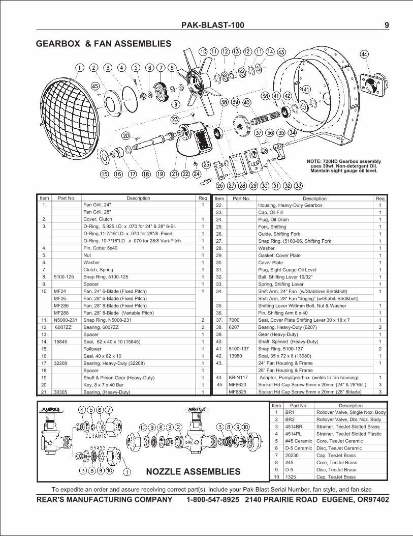
Item Part No. Description Req22. Housing, Heavy-Duty Gearbox 123. Cap, Oil Fill 124. Plug, Oil Drain 125. Fork, Shifting 126. Guide, Shifting Fork 127. Snap Ring, (5100-66, Shifting Fork 128. Washer 129. Gasket, Cover Plate 130. Cover Plate 131. Plug, Sight Gauge Oil Level 132. Ball, Shifting Lever 19/32" 133. Spring, Shifting Lever 134. Shift Arm, 24" Fan (w/Stabilizer Brkt&bolt) 1
Shift Arm, 28" Fan “dogleg” (w/Stabil. Brkt&bolt)35. Shifting Lever W/6mm Bolt, Nut & Washer 136. Pin, Shifting Arm 6 x 40 137. 7000 Seal, Cover Plate Shifting Lever 30 x 18 x 7 138. 6207 Bearing, Heavy-Duty (6207) 239. Gear (Heavy-Duty) 140. Shaft, Splined (Heavy-Duty) 141. 5100-137 Snap Ring, 5100-137 242. 13980 Seal, 35 x 72 x 8 (13980) 143. 24" Fan Housing & Frame 1
28" Fan Housing & Frame44. KBIN117 Adaptor, Pump/gearbox (welds to fan housing) 145 MF6620 Socket Hd Cap Screw 6mm x 20mm (24" & 28"6bl.) 3
MF6825 Socket Hd Cap Screw 6mm x 20mm (28" 8blade) 3
Item Part No. Description Req1. Fan Grill, 24" 1
Fan Grill, 28"2. Cover, Clutch 13. O-Ring, 5.925 I.D. x .070 for 24" & 28" 6-Bl. 1
O-Ring,11-7/16"I.D. x .070 for 28"/8 Fixed 1O-Ring, 10-7/16"I.D. .x .070 for 28/8 Vari-Pitch 1
4. Pin, Cotter 5x40 15. Nut 16. Washer 17. Clutch, Spring 18. 5100-125 Snap Ring, 5100-125 19. Spacer 110. MF24 Fan, 24" 6-Blade (Fixed Pitch) 1
MF26 Fan, 28" 6-Blade (Fixed Pitch)MF286 Fan, 28" 8-Blade (Fixed Pitch)MF288 Fan, 28" 8-Blade (Variable Pitch)
11. N5000-231 Snap Ring, N5000-231 212. 6007ZZ Bearing, 6007ZZ 213. Spacer 114. 15845 Seal, 62 x 40 x 10 (15845) 115. Follower 116. Seal, 40 x 62 x 10 117. 32208 Bearing, Heavy-Duty (32208) 118. Spacer 119. Shaft & Pinion Gear (Heavy-Duty) 120. Key, 8 x 7 x 40 Bar 121. 30305 Bearing, (Heavy-Duty) 1
GEARBOX & FAN ASSEMBLIES
NOTE: 720HD Gearbox assemblyuses 30wt. Non-detergent Oil.Maintain sight gauge oil level.
Item Part No. Description1 BR1 Rollover Valve, Single Noz. Body2 BR2 Rollover Valve, Dbl. Noz. Body3 4514BR Strainer, TeeJet Slotted Brass4 4514PL Strainer, TeeJet Slotted Plastic5 #45 Ceramic Core, TeeJet Ceramic6 D-5 Ceramic Disc, TeeJet Ceramic7 20230 Cap, TeeJet Brass8 #45 Core, TeeJet Brass9 D-5 Disc, TeeJet Brass10 1325 Cap, TeeJet Brass
NOZZLE ASSEMBLIES
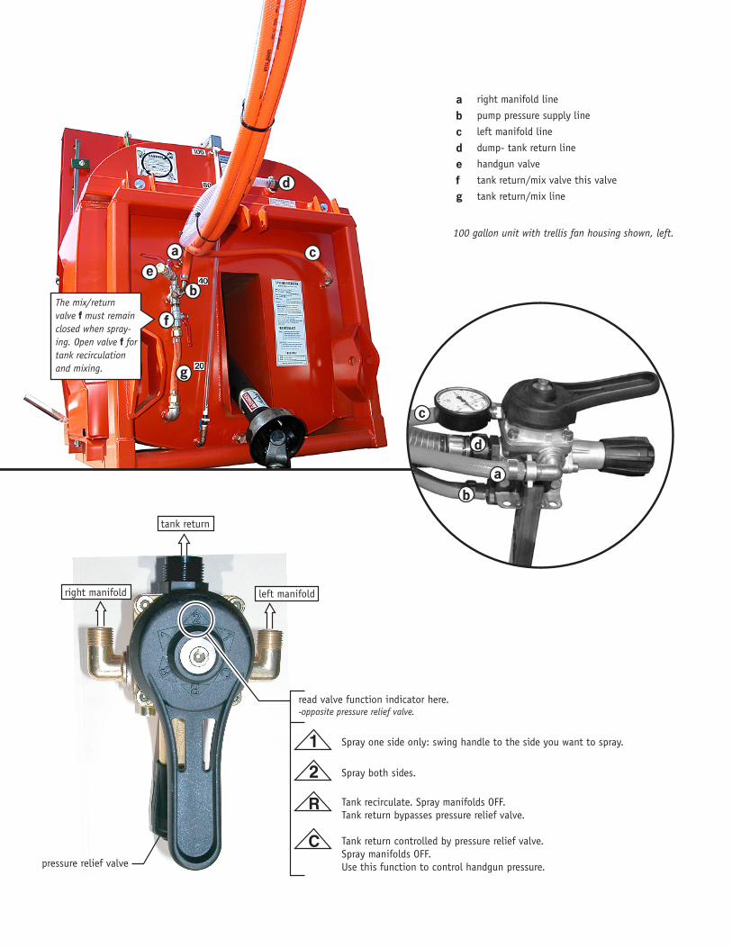
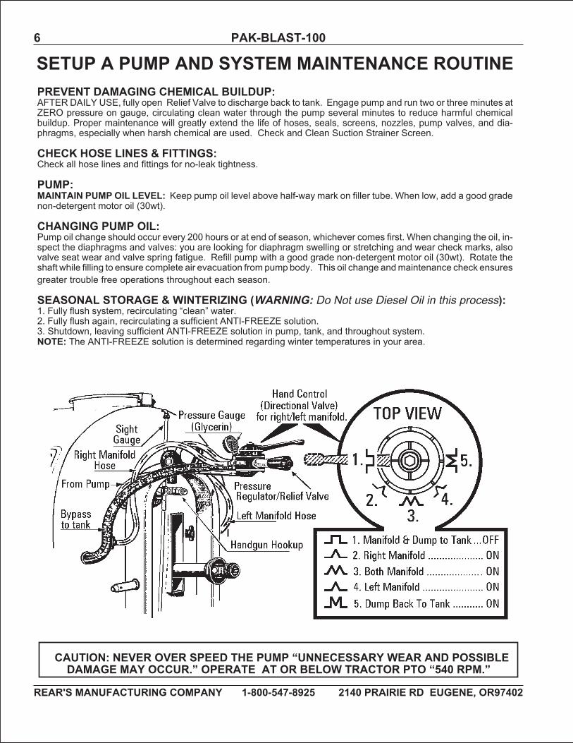
read valve function indicator here.-opposite pressure relief valve.
left manifold
tank return
right manifold
1
2
Spray one side only: swing handle to the side you want to spray.
Spray both sides.
R Tank recirculate. Spray manifolds OFF.Tank return bypasses pressure relief valve.
C Tank return controlled by pressure relief valve.Spray manifolds OFF.Use this function to control handgun pressure.pressure relief valve
c
a
d
b
abcdefg
right manifold line
pump pressure supply line
left manifold line
dump- tank return line
handgun valve
tank return/mix valve this valve
tank return/mix line
100 gallon unit with trellis fan housing shown, left.
c
be
f
g
a
d
The mix/return valve f must remain closed when spray-ing. Open valve f for tank recirculation and mixing.
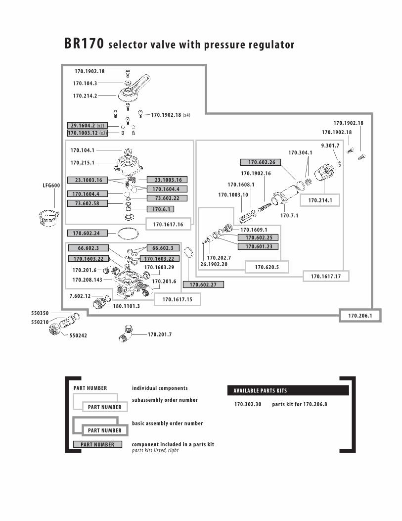
170.1603.22
BR170 selec tor valve with pressure regulator
LFG600
170.1902.18
170.104.3
170.214.2
170.1902.18 (x4)
29.1604.2 (x2)
170.1003.12 (x2)
170.1902.18
170.1902.18
9.301.7170.304.1
170.1902.16
170.1608.1
170.1003.10
170.1609.1
170.202.726.1902.20
170.201.6
170.201.6
170.1603.29
170.208.143
7.602.12
550350
550210
550242
180.1101.3
170.201.7
170.214.1
170.620.5
170.1617.17
170.206.1
170.302.30 par ts kit for 170.206.8
170.7.1
170.104.1
170.215.1
23.1003.16 23.1003.16
170.1604.4170.1604.4
170.602.24
73.602.22
170.602.26
170.602.25
170.601.23
73.602.58170.6.1
170.1617.16
170.1617.15
170.602.27
PART NUMBER
66.602.3 66.602.3
170.1603.22 170.1603.22
PART NUMBER
PART NUMBER
PART NUMBER
individual components
subassembly order number
basic assembly order number
component included in a par ts kitpar ts k its l isted, r ight
AVAILABLE PARTS KITS
REAR'S MANUFACTURING COMPANY 1-800-547-8925 2140 PRAIRIE RD EUGENE, OR97402
12 PAK-BLAST-100
ITEM PART NO. DESCRIPTION REQ
1 124-1-1/4-AL Strainer, SprayingSystems 1-1/4"Alum/Ny.
1
2 12287-1-1/4"AL
Cap, 1-1/4" Alum. 1
3 12290-3-SS Screen, 50 Mesh 1Screen,Screen,
4 12291-BU Gasket 15 12288-NY Bowl, Nylon 1
SUCTION STRAINER124-1-1/4"AL
ITEM PART NO. MOUNTING GREENWARE REQ
1 KBIN4511 TOP-LINK, EQUIPMENT HALF 1
2 0750500HP HITCH PIN, 3/4"X 5" LONG 1
3 CHP6 HAIR PIN, .177" X 3-11/16" 1
4 NUT & BOLT, 3/4"X 2"NC TOP-LINK 2
5 KBIN4512 TOP-LINK, TRACTOR HALF 1
6 HS42R EYELET BRACKET, ANTI-SAG CHAINRIGHT
1
7 0310275SNAP SNAPPER PIN, 5/16" X 2-3/4” OAL 2
8 HS42L EYELET BRACKET, ANTI-SAG CHAIN LEFT 1
9 CVH41-17-1 PIN, CATEGORY NO.1 W/CAT.1 THREADS) 2
10 HS43CH1 SWAY BRACE CHAIN FOR CAT.1 OR 2 PIN 2
DL3O3 PTO DRIVELINE 1-3/8" 6-SPLINE LOCK AT BOTH ENDS
LID ADJUSTMENT: After a period of use, the lid latch may losesome of its tautness. Remedy this by widening the space betweenthe lid and the hinge: adjust the nut on the lid bolt until the desiredlatch tautness is achieved.

REAR'S MANUFACTURING COMPANY 1-800-547-8925 2140 PRAIRIE RD EUGENE, OR97402
14 PAK-BLAST-100
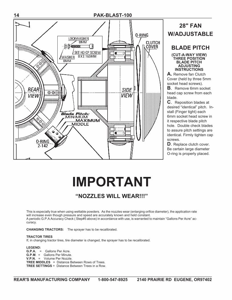
IMPORTANT“NOZZLES WILL WEAR!!!”
This is especially true when using wettable powders. As the nozzles wear (enlarging orifice diameter), the application ratewill increase even though pressure and speed are accurately known and held constant.A periodic G.P.A Accuracy Check ( Step#5 above) in accordance with use, is warranted to maintain “Gallons Per Acre” ac-curacy.
CHANGING TRACTORS: The sprayer has to be recalibrated.
TRACTOR TIRESIf, in changing tractor tires, tire diameter is changed, the sprayer has to be recalibrated.
LEGEND:G.P.A. = Gallons Per Acre.G.P.M. = Gallons Per Minute.V.P.N. = Volume Per Nozzle.TREE MIDDLES = Distance Between Rows of Trees.TREE SETTINGS = Distance Between Trees in a Row.
28" FANW/ADJUSTABLE
BLADE PITCH(CUT-A-WAY VIEW)THREE POSITIONBLADE PITCHADJUSTING
INSTRUCTIONSA. Remove fan ClutchCover (held by three 5mmsocket head screws).B. Remove 6mm sockethead cap screw from eachblade.C. Reposition blades atdesired “identical” pitch. In-stall (Finger tight) each6mm socket head screw init respective blade pitchhole. Double check bladesto assure pitch settings areidentical. Firmly tighten capscrews.D. Replace clutch cover.Be certain large diameterO-ring is properly placed.

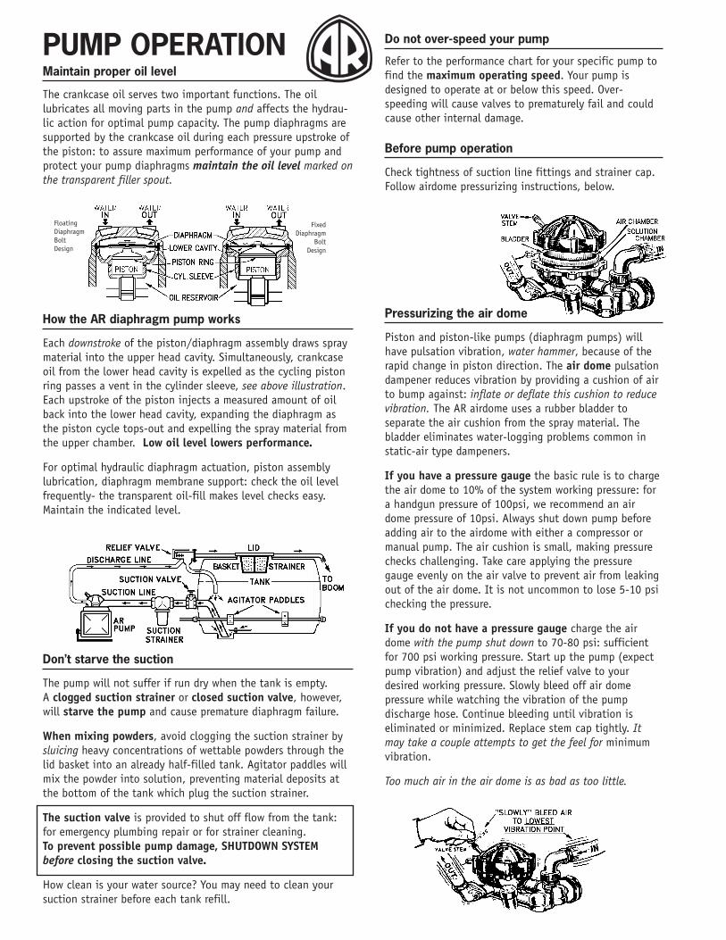
Maintain proper oil level
The crankcase oil serves two important functions. The oillubricates all moving parts in the pump and affects the hydrau-lic action for optimal pump capacity. The pump diaphragms aresupported by the crankcase oil during each pressure upstroke ofthe piston: to assure maximum performance of your pump andprotect your pump diaphragms maintain the oil level marked onthe transparent filler spout.
How the AR diaphragm pump works
Each downstroke of the piston/diaphragm assembly draws spraymaterial into the upper head cavity. Simultaneously, crankcaseoil from the lower head cavity is expelled as the cycling pistonring passes a vent in the cylinder sleeve, see above illustration.Each upstroke of the piston injects a measured amount of oilback into the lower head cavity, expanding the diaphragm asthe piston cycle tops-out and expelling the spray material fromthe upper chamber. Low oil level lowers performance.
For optimal hydraulic diaphragm actuation, piston assemblylubrication, diaphragm membrane support: check the oil levelfrequently- the transparent oil-fill makes level checks easy.Maintain the indicated level.
Don’t starve the suction
The pump will not suffer if run dry when the tank is empty.A clogged suction strainer or closed suction valve, however,will starve the pump and cause premature diaphragm failure.
When mixing powders, avoid clogging the suction strainer bysluicing heavy concentrations of wettable powders through thelid basket into an already half-filled tank. Agitator paddles willmix the powder into solution, preventing material deposits atthe bottom of the tank which plug the suction strainer.
The suction valve is provided to shut off flow from the tank:for emergency plumbing repair or for strainer cleaning.To prevent possible pump damage, SHUTDOWN SYSTEMbefore closing the suction valve.
How clean is your water source? You may need to clean yoursuction strainer before each tank refill.
Do not over-speed your pump
Refer to the performance chart for your specific pump tofind the maximum operating speed. Your pump isdesigned to operate at or below this speed. Over-speeding will cause valves to prematurely fail and couldcause other internal damage.
Before pump operation
Check tightness of suction line fittings and strainer cap.Follow airdome pressurizing instructions, below.
Pressurizing the air dome
Piston and piston-like pumps (diaphragm pumps) willhave pulsation vibration, water hammer, because of therapid change in piston direction. The air dome pulsationdampener reduces vibration by providing a cushion of airto bump against: inflate or deflate this cushion to reducevibration. The AR airdome uses a rubber bladder toseparate the air cushion from the spray material. Thebladder eliminates water-logging problems common instatic-air type dampeners.
If you have a pressure gauge the basic rule is to chargethe air dome to 10% of the system working pressure: fora handgun pressure of 100psi, we recommend an airdome pressure of 10psi. Always shut down pump beforeadding air to the airdome with either a compressor ormanual pump. The air cushion is small, making pressurechecks challenging. Take care applying the pressuregauge evenly on the air valve to prevent air from leakingout of the air dome. It is not uncommon to lose 5-10 psichecking the pressure.
If you do not have a pressure gauge charge the airdome with the pump shut down to 70-80 psi: sufficientfor 700 psi working pressure. Start up the pump (expectpump vibration) and adjust the relief valve to yourdesired working pressure. Slowly bleed off air domepressure while watching the vibration of the pumpdischarge hose. Continue bleeding until vibration iseliminated or minimized. Replace stem cap tightly. Itmay take a couple attempts to get the feel for minimumvibration.
Too much air in the air dome is as bad as too little.
PUMP OPERATION
FloatingDiaphragmBoltDesign
FixedDiaphragm
BoltDesign
After each use
Run pump for five minutes with clean water. These few minutesof flushing are well spent: extend diaphragm life, minimizechemical buildup throughout your spray system.
PUMP MAINTENANCE
After every 200 hours AND at season’s end
Inspect diaphragms for wear marks, swelling, and stretching.See the diaphragm replacement instructions, below.Check valves for spring fatigue and seat wear.Change the oil- the crankcase oil capacity is in your pumpmanual. Use a 30W non-detergent oil. Rotate the pump shaftby hand while filling to evacuate air pockets. With pump level,the crankcase is full when oil level reaches the indicator on thetransparent fill neck. Run pump for 10 minutes under no loadconditions to evacuate remaining air pockets. Recheck oil level.During first field run, check oil color closely. If it should turnmilky, the diaphragms were not correctly seated.
Winter storage
Run pump for five minutes with clean water. Then, with suctionand discharge valves open and the tank empty, run pump fiveminutes to ensure complete drainage of pump heads and lines.A gallon of anti-freeze recirculated through the system and leftin place after shut down completes your winterizing. Allowanti-freeze to replace any possible water in hoses and booms. Ifa handgun is in the system, run anti-freeze through the hoseand handgun, returning the spray into the tank through the lid.Two gallons of anti-freeze may be required to winterize systemswith handgun lines.
HANDLE AGRICULTURAL CHEMICALS WITH CARE
USE THE PERSONAL PROTECTIVE EQUIPMENTRECOMMENDED BY THE CHEMICAL MANUFACTURER
WHEN MAINTAINING SPRAY EQUIPMENT!
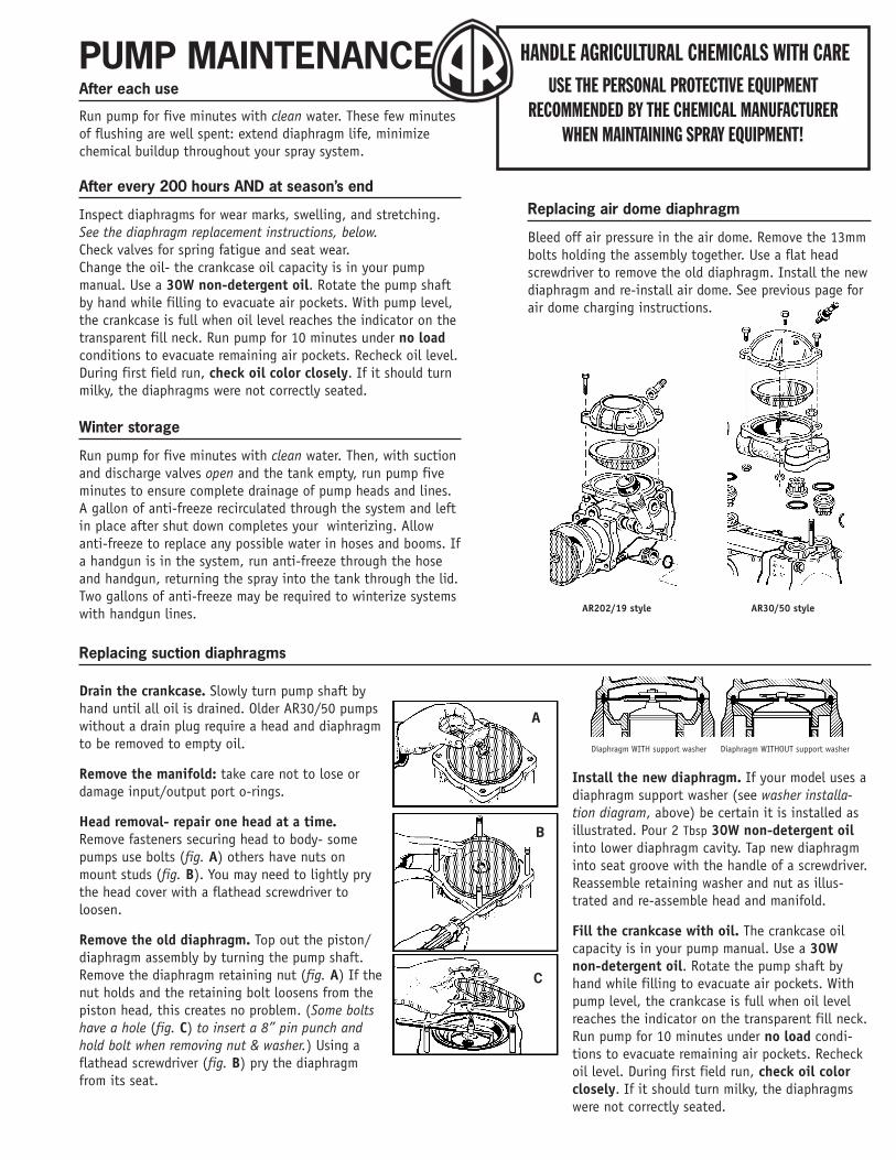
Replacing air dome diaphragm
Bleed off air pressure in the air dome. Remove the 13mmbolts holding the assembly together. Use a flat headscrewdriver to remove the old diaphragm. Install the newdiaphragm and re-install air dome. See previous page forair dome charging instructions.
AR202/19 style AR30/50 style
A
B
C
Replacing suction diaphragms
Drain the crankcase. Slowly turn pump shaft byhand until all oil is drained. Older AR30/50 pumpswithout a drain plug require a head and diaphragmto be removed to empty oil.
Remove the manifold: take care not to lose ordamage input/output port o-rings.
Head removal- repair one head at a time.Remove fasteners securing head to body- somepumps use bolts (fig. A) others have nuts onmount studs (fig. B). You may need to lightly prythe head cover with a flathead screwdriver toloosen.
Remove the old diaphragm. Top out the piston/diaphragm assembly by turning the pump shaft.Remove the diaphragm retaining nut (fig. A) If thenut holds and the retaining bolt loosens from thepiston head, this creates no problem. (Some boltshave a hole (fig. C) to insert a 8” pin punch andhold bolt when removing nut & washer.) Using aflathead screwdriver (fig. B) pry the diaphragmfrom its seat.
Diaphragm WITH support washer Diaphragm WITHOUT support washer
Install the new diaphragm. If your model uses adiaphragm support washer (see washer installa-tion diagram, above) be certain it is installed asillustrated. Pour 2 Tbsp 30W non-detergent oilinto lower diaphragm cavity. Tap new diaphragminto seat groove with the handle of a screwdriver.Reassemble retaining washer and nut as illus-trated and re-assemble head and manifold.
Fill the crankcase with oil. The crankcase oilcapacity is in your pump manual. Use a 30Wnon-detergent oil. Rotate the pump shaft byhand while filling to evacuate air pockets. Withpump level, the crankcase is full when oil levelreaches the indicator on the transparent fill neck.Run pump for 10 minutes under no load condi-tions to evacuate remaining air pockets. Recheckoil level. During first field run, check oil colorclosely. If it should turn milky, the diaphragmswere not correctly seated.
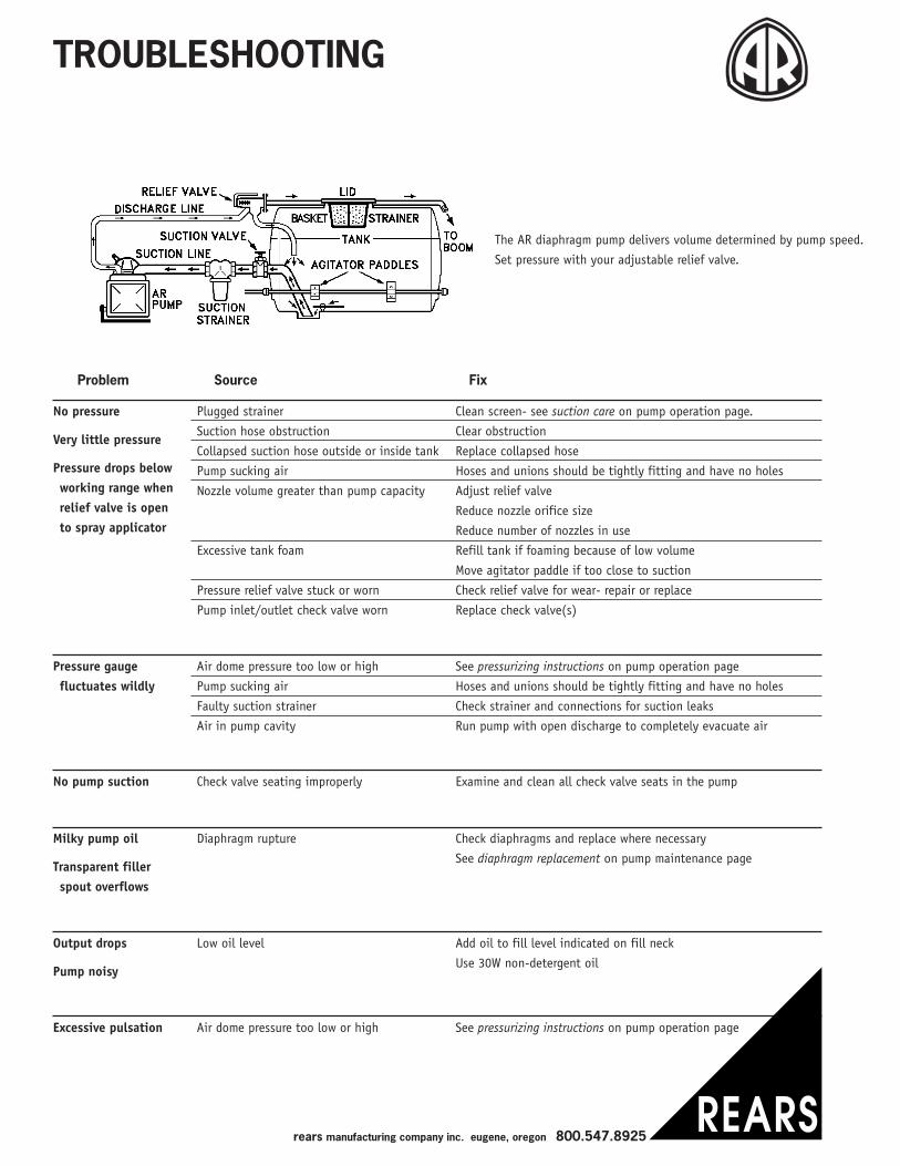
TROUBLESHOOTING
The AR diaphragm pump delivers volume determined by pump speed.
Set pressure with your adjustable relief valve.
Pressure gaugefluctuates wildly
Air dome pressure too low or high
Pump sucking air
Faulty suction strainer
Air in pump cavity
See pressurizing instructions on pump operation page
Hoses and unions should be tightly fitting and have no holes
Check strainer and connections for suction leaks
Run pump with open discharge to completely evacuate air
No pump suction Check valve seating improperly Examine and clean all check valve seats in the pump
Milky pump oil
Transparent fillerspout overflows
Diaphragm rupture Check diaphragms and replace where necessary
See diaphragm replacement on pump maintenance page
Output drops
Pump noisy
Low oil level Add oil to fill level indicated on fill neck
Use 30W non-detergent oil
Excessive pulsation Air dome pressure too low or high See pressurizing instructions on pump operation page
No pressure
Very little pressure
Pressure drops belowworking range whenrelief valve is opento spray applicator
Plugged strainer
Suction hose obstruction
Collapsed suction hose outside or inside tank
Pump sucking air
Nozzle volume greater than pump capacity
Excessive tank foam
Pressure relief valve stuck or worn
Pump inlet/outlet check valve worn
Clean screen- see suction care on pump operation page.
Clear obstruction
Replace collapsed hose
Hoses and unions should be tightly fitting and have no holes
Adjust relief valve
Reduce nozzle orifice size
Reduce number of nozzles in use
Refill tank if foaming because of low volume
Move agitator paddle if too close to suction
Check relief valve for wear- repair or replace
Replace check valve(s)
Problem Source Fix
rears manufacturing company inc. eugene, oregon 800.547.8925
2211 33 44
11 22 33
44 55 66
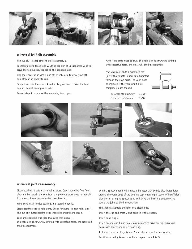
universal joint disassembly
Remove all (4) snap rings in cross assembly 1.
Position joint in loose vice 2. Strike top arm of unsupported yoke to
drive the top cup up. Repeat on the opposite side.
Grip loosened cup in vice 3 and strike yoke arm to drive yoke off
cup. Repeat on opposite cup.
Support cross in loose vice 4 and strike yoke arm to drive the top
cup up. Repeat on opposite side.
Repeat step 3 to remove the remaining two cups.
universal joint reassembly
Clean bearings 1 before assembling cross. Cups should be free from
dirt- and be certain the seal from the previous cross does not remain
in the cup. Smear grease in the clean bearing.
Make certain all needle bearings are seated properly.
Clean bearing seat in yoke arms. Check for burrs (in new yokes also).
File out any burrs: bearing seat should be smooth and clean.
Yoke arms must be true (see true yoke test, above).
If a yoke arm is sprung by striking with excessive force, the cross will
bind in operation.
Note: Yoke arms must be true. If a yoke arm is sprung by striking
with excessive force, the cross will bind in operation.
Where a spacer is required, select a diameter that evenly distributes force
around the outer edge of the bearing cup. Choosing a spacer of insufficient
diameter or using no spacer at all will drive the bearings unevenly and
cause the joint to bind in operation.
You should assemble the joint in a clean area.
Insert the cup and cross 2 and drive in with a spacer.
Insert snap ring 3.
Insert second cup 4 and hold cross in place to drive on cup. Drive cup
down with spacer and insert snap ring.
To loosen cross, strike yoke arm 5 and check cross for free rotation.
Position second yoke on cross 6 and repeat steps 2 to 5.
True yoke test- slide a machined rod
(a few thousandths under cup diameter)
through the yoke arms. The yoke must
be replaced if the yoke won’t slide
completely onto the rod.
55 series rod diameter 1.530”
35 series rod diameter 1.247
Rears Manufacturing Company Incorporated, hereafter referred to as Rears, makes every effort to assure that its products meet high quality and durability standards subject to the provisions hereinafter set forth. Rears does hereby warrant to the original purchaser of each product manufactured by Rears for a period of ninety (90) days from the date of purchase or five hundred (500) hours of operation, whichever occurs first, that such product will be free from defects in material and workmanship under normal use with normal maintenance service. This warranty does not cover component parts of products manufactured by Rears when such component parts are subject to a manufacturer’s warranty. In addition, this warranty does not cover pressure gauges.
THE EXCLUSIVE REMEDY FOR ANY DEFECTS COVERED BY THIS WARRANTY SHALL BE THE OBLIGATION OF REARS TO REPAIR OR REPLACE ANY PARTS OF SAID PRODUCTS WHICH SHALL, WITHIN NINETY (90) DAYS FROM THE DATE OF PURCHASE OR FIVE HUNDRED (500) HOURS OF OPERATION, WHICHEVER OCCURS FIRST, BE DETERMINED TO THE SATISFACTION OF REARS UPON REARS’ EXAMINATION, TO HAVE BEEN THUS DEFECTIVE.
In order to take advantage of this limited warranty the defective product must be returned for examination, freight pre-paid, to Rears or an authorized dealer designated by Rears. Proof of purchase date and explanation of the defect must accompany the returned product.
REARS MAKES NO EXPRESSED OR IMPLIED WARRANTIES OF ANY KIND, INCLUDING THE IMPLIED WARRANTIES OF MERCHANT-ABILITY AND OF FITNESS FOR ANY PARTICULAR PURPOSE OTHER THAN STATED HEREIN.
The limited warranty contained herein shall not apply to any product if it shall have been repaired or altered by personnel not authorized by Rears or if the product shall have been subject to misuse, negligence or accident.
THE REMEDIES PROVIDED HEREIN ARE THE EXCLUSIVE REMEDIES TO THE PURCHASER AND REARS SHALL NOT BE LIABLE TO THE PURCHASER OR ANY OTHER PARTY FOR INCIDENTAL, CONSEQUENTIAL OR SPECIAL DAMAGES OR ANY CAUSE, LOSS, AC-TION, CLAIM OR DAMAGE WHATSOEVER FOR INJURY TO PERSON OR PROPERTY OR ANY CONSEQUENTIAL ECONOMIC OR INCI-DENTAL LOSS RESULTING FROM ANY DEFECT IN MATERIALS OR WORKMANSHIP OF THE PRODUCT SOLD.
Rears will assign to the original purchaser upon request all warranties on component parts if permitted by the manufacturer of such component parts.
Dealer Name
LIMITED WARRANTY
Purchaser Name Purchase Date
Address State/Zip
Model Serial Number
PhoneSales person
City
Address State/ZipCity


![Karachi Sewerage Project (Loans 1001-PAK[SF] & 1002-PAK)](https://static.fdocuments.us/doc/165x107/577ce66d1a28abf10392ca54/karachi-sewerage-project-loans-1001-paksf-1002-pak.jpg)


![PAK-A-PUNCH & KEY BLANK REFERENCE - ABsupply.net · 2015-11-18 · pak-a-punch & key blank reference ... valet an1-an9282 x9/73vb pak-v1 v01 acces pak-90v 90deg ... [-p] pak-v1 v01](https://static.fdocuments.us/doc/165x107/5b3896967f8b9a5a518d9b59/pak-a-punch-key-blank-reference-2015-11-18-pak-a-punch-key-blank-reference.jpg)