
P & S ETHERNET - IT Telkom PWTekofajarcahyadi.dosen.st3telkom.ac.id/.../2017/02/Perte… · ·...
40
Transcript of P & S ETHERNET - IT Telkom PWTekofajarcahyadi.dosen.st3telkom.ac.id/.../2017/02/Perte… · ·...

OVERVIEW
Materi Pra-UTS:
1. Hub, Bridge, & Switch
2. Ethernet
3. VLAN
4. Firewall
5. Disiplin Antrian

TUJUAN
Mahasiswa dapat menjelaskan pengertian dan cara kerja jaringan Ethernet
To have a basic idea what is a Local Area Network
To understand further the Ethernet standards used in LAN technologies
To find out what are the basic factors that can impact an Ethernet delay in a local area network
Mahasiswa dapat mensimulasikan performansi jaringan ethernet dengan simulasi OPNET

READING SECTION
Baca:
Computer Networks A System Approach, Larry L. Peterson, Bruce S. Davie, Section 2.6 (Ethernet 802.3), Hal. 116

ETHERNET (802.3) [TAMBAHAN]
Dikembangkan sejak tahun 1970, oleh Xerox Palo Alto Reasearch Center (PARC)
Ethernet menggunakan metode Carrier Sense CSMA/CD
Cikal bakal Ethernet ALOHA (Dikembangkan oleh University of Hawaii)
“Core idea” dari Ethernet dan ALOHA Algoritma yang mengontrol waktu kapansebuah node dapat transmit
Digital Equipment Corporation dan Intel, bersama dengan Xerox PARCmendefinisikan standard Ethernet 10 Mbps (1978) yang nantinya dikenal denganstandard IEEE 802.3

LOCAL AREA NETWORK
A local area network or LAN is composed of a single or groups of computer networkwhich is locally situated in a geographical area like in a building, either at school, athome, or office. The network is arranged into a certain layout in which computers andnetwork devices are connected together in order for them to communicate known asnetwork topology.
Star topology is one of the network topologies used to layout the wire in connecting theworkstations to a central point like switch. In LAN, switches and cables are the commontransmission medium used to broadcast information from one device (source) to another(destination), and that when Ethernet protocol comes into play.

ETHERNET TECHNOLOGY
The main concept of Ethernet is to interconnect physical devices to transmit data fromsource to destination in order to share data, devices and Internet connection. Thesimplicity and efficiency of Ethernet make it a widely used communication protocol inboth LANs and Wide Area Networks (WANs), has and it continues to evolve.
Just as with human communication, computer networks use rules or protocols ofcommunication for successful message transmission and delivery.

ETHERNET TECHNOLOGY
Ethernet protocol is the common “language spoken” in Layers 1 and 2 of the OSImodel. At the physical layer (Layer 1) Ethernet standards exist for data transmissionover a physical medium, including standards for cable type, cabling distancelimitations, connectors, and voltage. At the data link layer (Layer 2) standardsdetermine how Ethernet frames are transmitted via packets from a source to adestination. An Ethernet switch is a common Layer 2 device used to forward theEthernet frames.
The Institute of Electrical and Electronic Engineers (IEEE) is the organization responsiblefor approving and maintaining industry standards for connections, media requirementsand communication protocols. The organization is necessary to ensure that productsdeveloped by various manufacturers are universally compatible with each other.Standards to improve Ethernet technology have resulted in a faster and more flexiblemethod of data transmission as listed below.

ETHERNET TECHNOLOGY
a. IEEE 802.3i, 10BaseT standard for 10 Mbps Ethernet over unshielded twisted pair(UTP) cable. IEEE 802.3j 10BaseF standard for fiber optic cable
b. IEEE 802.3u, Fast Ethernet or 100Base-xx standard for 100 Mbps over UTP andfiber cable
c. IEEE 802.3ab, 1000BaseT standard for Gigabit Ethernet over twisted pair.
d. IEEE 802.3an, 10GBaseT standard for 10 Gigabit Ethernet over UTP.

ETHERNET TECHNOLOGY
The specifications above means, for example a 1000BaseT Ethernet can transfer datainto a speed of 1000 megabits per second. In opposed to the original design ofEthernet which used the coaxial cable in early 1980s, the 10BaseT Ethernet networkover twisted pair was adopted easily due to the fact that commercial buildingsalready have telephone wiring installed that uses UTP cables. The telephone wiringinstalled has been layout into a star topology, yet coaxial cable has to be layout as abus topology. So, it was cheaper to use UTP cable since the foundation alreadyexisted. The only thing needed was to expand the installed base and that able toleverage the existing building design for telephone wirings.

ETHERNET CABLE STANDARD
Ethernet networks commonly use Category 6 UTP cable, also known as GigabitEthernet standards, shown in Figure 1. The cable can transmit data at speeds of up to1000 Mbps. Category 6 can perform up to 250 MHz in a maximum length of 100meters and is backward compatible with Category 5/5e. The latest UTP cablestandard is the Augmented Category 7, known as Category 7a, which is capable of upto 10 Gbps with 500 MHz performance and improved functionality for minimizingcrosstalk.

STRAIGHT THROUGH CABLE
Ethernet straight-through cable is used to connect two different devices, for example a workstation to a switch
You can determine that a cable is straight-through if like-colored pins in both ends of the cable align with each other
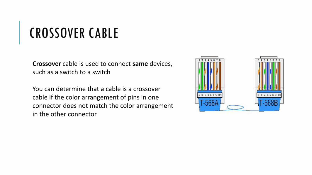
CROSSOVER CABLE
Crossover cable is used to connect same devices, such as a switch to a switch
You can determine that a cable is a crossover cable if the color arrangement of pins in one connector does not match the color arrangement in the other connector

10 MBITS/S DAN 100 MBITS/S STANDARDS
10Base-T 100Base-TX
Media Cat 3, 4, 5 UTP 2 pairs Cat 5 UTP 2 pairs
Max. Segment Length 100 m 100 m
Connector RJ45 RJ45
Standard 802.3 (14) 802.3 (24)

GIGABITS/S STANDARDS
1000Base-T 1000Base-SX 1000Base-LX 1000Base-ZX
Media Cat 5E UTP 4
pairs
850 nm
50µm & 65µm,
Multimode Fiber
1310 nm
50µm Multimode
Fiber
9µm Singlemode
Fiber
1550 nm
Singlemode Fiber
Max. Segment
Length
100 m 500 m (50µm),
220 m (65µm)
10 km (SM)
550 m (MM)
100 km
Connector RJ45 SC/LC SC/LC SC/LC

10GE STANDARDS
10GBase-SR 10GBase-LR 10GBase-ER 10GBase-
SW
10GBase-
LW
10GBase-
EW
Media 850 nm
50µm
Multimode
Fiber
1310 nm
9µm
Singlemode
Fiber
1550 nm
Singlemode
Fiber
850 nm
50µm
Multimode
Fiber
1310 nm
9µm
Singlemode
Fiber
1550 nm
Singlemode
Fiber
Max.
Segment
Length
300 m 10 km 30 km 300 m 10 km 30 km
Connector SC SC SC SC SC SC
PHY LAN LAN LAN WAN WAN WAN

ETHERNET CABLING

PROJECT
I would like to start a small customer care and technical support services businesscalled iCareMore in Monterey, California. The company will start with 15 employees,with 5 employees assigned to departments for Billing, Technical, and Sales. Alldepartments use email, database and web applications on their workstations. TheBilling and Sales departments are located on the first floor. The Technical departmentis on the second floor. Considering I have to double my employees in a few months,would it cause a problem with the network’s performance?

STEP#1
Anda akan membuat sebuah project yang terdiri dari 3 (tiga) scenario.
• Buatlah project dengan nama: NIM_project2
• Buatlah scenario dengan nama: 10Mbps_15
(Kemudian nantinya di duplicate) 10Mbps_30
100Mbps_30
• OK

STEP#2
Setting empty scenario
• Create empty scenario
• Pilih skala jaringan: Office
• X span : 100 m
• Y span : 100 m
• Ethernet technology: Yes

STEP#3
Setup a network
• Gunakan fitur rapid configurationuntuk membuat topologi jaringanseperti gambar di samping
• Center node model: ethernet16_switch
• Prphry node model: ethernet_wkstn
• Link model: 10BaseT
• Center; X: 45 ; Y: 25
• Number: 10
• Radius: 18
Center; X: 45 ; Y: 70
Number: 5
Radius: 15

STEP#4
Application configuration & Profile configuration
• Gunakan Object Palette Tree untuk membuat node:
• Application Config• Profile Config• Server• Link Switch_Lantai1 Switch_Lantai2

STEP#5
Menentukan aplikasi yang akan digunakan pada Application configuration.
• Application configuration Klik kanan Edit attributes
• Application Definitions Default
• OK

STEP#6
Menentukan Profile configuration
Menentukan profile dari setiap aplikasi yang akan digunakan.
• Prifle configuration Klik kanan Edit attributes.
• Profile configuration Edit.
• Next Step#7

STEP#7
Membuat Profile Name
• Billing Profile
• Sales Profile
• Teknis Profile
• Next Step#8

STEP#8
Aplikasi yang akan digunakan pada Billing Profile:
• Database Access (Heavy)
• Email (Heavy)
• Web Browsing (Heavy)
Contoh untuk Billing Profile,
masukkan juga nilai untuk
Sales Profile dan Teknis
Profile sesuai tabel

STEP#9
Konfigurasi server
• Server Klik kanan Edit attributes
• Application: Supported services Edit.
• (Application: Supported services) Table Kolom Rows Isi dengan angka 6
• Isikan enam jenis service seperti gambar di samping

STEP#10
Konfigurasi Divisi Billing
• Pilih kelima workstation pada
divisi Billing (Billing_1 s/d Billing_5) Edit attributes Application: Supported Profiles Edit
• (Application: Supported Profiles) Table Rows 1
• Profile Name Billing Profile OK
• Apply to selected objects OK

STEP#11
• Ulangi Step#10 untuk melakukan konfigurasi pada Divisi Sales dan Divisi Teknis
• Nama profile untuk Divisi Sales dan Divisi Teknis secara berurutan adalah: Sales Profile dan Teknis Profile
• Ctrl+S untuk menyimpan project.

STEP#12
Choosing statistics:
• Klik kanan di bagian kosong Choose Individual DES Statistics
• Pilih Global Statistics Pilih Ethernet Pilih juga HTTP (Traffic Received [packet/sec] & Traffic Sent [packet/sec])
• OK

STEP#13
Duplicating scenario:
• Pada step ini, kita akan membuat scenario kedua, (setelah scenario pertama, 10Mbps_15), yaitu 10Mbps_30 (Menggunakan link 10 Mbps dengan 30 workstation).
• Ganti model Switch_Lantai1 dengan ethernet32_switch (Klik kanan Edit attributes (advanced)
• Pada scenario 2, (seperti perintah soal) jumlah karyawan pada setiap divisi digandakan untuk melihat seperti apa pengaruhnya pada performansi jaringan?
Scenario 2

STEP#14
• Untuk menambahkan workstation pada setiap divisi seperti pada Step#13, silahkan copy paste masing-masing 5 (lima) workstation pada setiap divisi untuk menambahkan 5 (lima) workstation lagi pada tiap2 divisi.
• Untuk copy paste, klik satu workstation, kemudian klik workstation lainnya dengan menekan tombol Ctrl secara bersamaan. Kemudian Ctrl+C Ctrl+V.
• Untuk menambahkan link pada workstation baru menuju Switch_Lantai1 dan Switch_Lantai2, dapat menggunakan “Object Palette”
• Pilih Shared Object Palette ethernet link models 10BaseT
• Cara menghubungkan link ke node Step#15

STEP#15
Menghubungkan link ke node:
• Klik link yang akan dipilih, dalam kasus ini 10BaseT (lingkaran hijau)
• Maka akan muncul keterangan link 10BaseT di sebelah kanan atas (lingkaran merah)
• Klik pada keterangan tersebut (lingkaran merah), kemudian hubungkan link tersebut ke node yang akan dihubungkan
• Klik tombol Esc untuk keluar dari pilihan (link) tersebut

STEP#16
Membuat scenario 3 (Duplicate dari scenario 2):
• Membuat scenario 3 dengan nama 100Mbps_30 (menggunakan link 100 Mbps [100BaseT] dengan jumlah workstation 30 buah) dari scenario 2
• Sekali lagi yang membedakan antara scenario 2 dan 3 adalah semua link yang menghubungkan Switch_Lantai1 ke Switch_Lantai2, Switch_lantai2 ke Server, dan Switch ke semua workstation.
• Untuk mengganti model link tersebut, gunakan select similar links menggunakan langkah yang sama dengan mengganti model Switch
Scenario 3
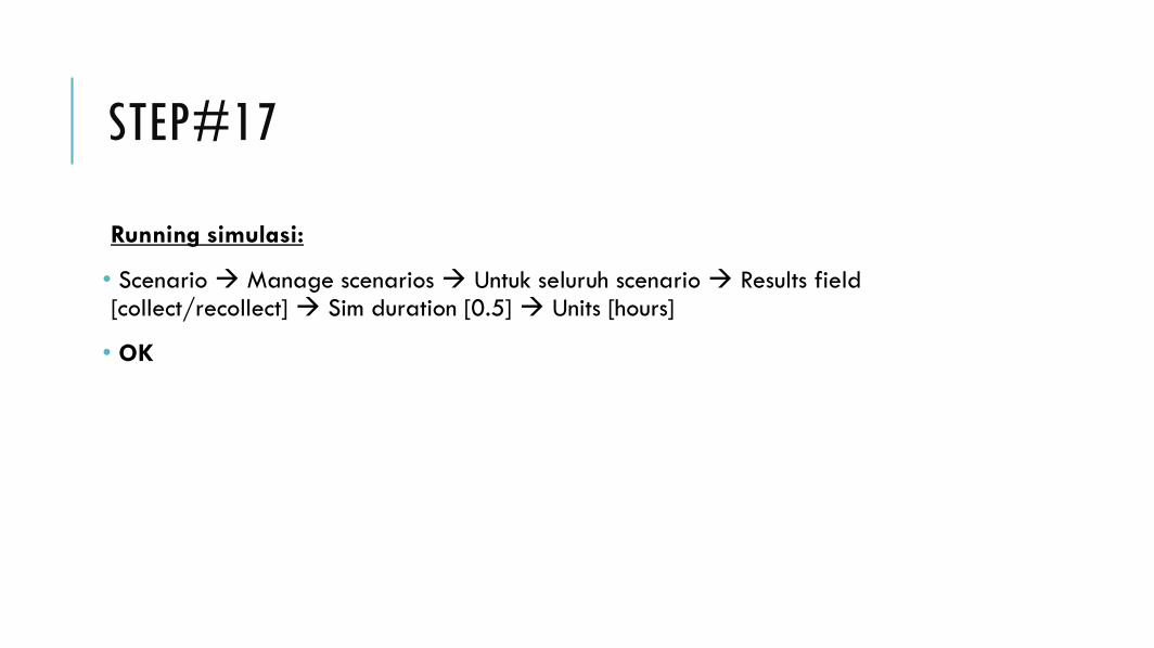
STEP#17
Running simulasi:
• Scenario Manage scenarios Untuk seluruh scenario Results field [collect/recollect] Sim duration [0.5] Units [hours]
• OK

STEP#18
Analisis hasil:
• Traffic Sent (packet/sec)

STEP#19
Analisis hasil:
• Traffic received (packet/sec)

STEP#20
Analisis hasil:
• Overall delay (sec)

TUGAS
1. File project, dengan nama: NIM_project2
2. Analisis grafik hasil simulasi di atas, hubungan antara traffic sent (load) dan traffic received (throughput) packet, serta delay ketiga scenario
3. Apa yang mempengaruhi nilai delay, dan apa akibat dari nilai delay terhadap masing-masing scenario? Jelaskan apa dampak dari penambahan jumlah karyawan terhadap performansi jaringan perusahaan tersebut?
Semakin detil analisis anda, maka semakin baik...

Terima kasih...