
P A I N T S P R A Y I N G E Q U I P M E N T GHIBLI PUMP 10:1 · PDF fileGhibli pump is...
28
PAINT SPRAYING EQUIPMENT Ed. 003 -04/2013 USE AND MAINTENANCE MANUAL www.larius.com II 2 G c IIB T6 A T E X C E R T I F I C A T E ENGLISH GHIBLI PUMP 10:1
-
Upload
nguyenkiet -
Category
Documents
-
view
212 -
download
0
Transcript of P A I N T S P R A Y I N G E Q U I P M E N T GHIBLI PUMP 10:1 · PDF fileGhibli pump is...

P A I N T S P R A Y I N G E Q U I P M E N T
Ed. 003 -04/2013
US
E A
ND
MA
INT
EN
AN
CE
MA
NU
AL
www.larius.com
II 2 G c IIB T6
A t e x C e r t i f i C A t e
ENGLISH
GHIBLI PUMP 10:1

VEGA 5:1
www.larius.com
P33 1:1P31 2:1
VEGA 23:1
GHIBLI 3:1
GHIBLI 30:1GHIBLI 40:1
OMEGA 10:1
OMEGA 23:1OMEGA 30:1
NOVA 20:1NOVA 45:1NOVA 60:1NOVA 68:1
PISTO
N PNE
UMAT
IC TR
ANSF
ER PU
MPS

www.larius.com
P A I N T S P R A Y I N G E Q U I P M E N T
WORKING PRINCIPLE
The pneumatic transfer pumps work with a compressed air motor that moves the piston vertically from top to bottom and viceversa. The product is suctioned by the lower pump and carried to the exit.
The structure of the "pumping unit" (suction valve, pump piston, material seal gaskets) permits the supply ofmaterial when the piston is in the ascending or descending phase.
The flow rate of a pneumatic piston pump depends on the quantity of material that it releases during each cycle and on the number of cycles that it completes (the cycle is the full stroke of the piston in both direc-tions).
Pneumatic piston pumps are divided into two types:
IN-LINE: the pneumatic motor and the pump constitute one single bodyDIVORCED: the pneumatic motor is separated from the pump and the fluid is not in contact with the motor.
ADVANTAGES OF USE
- Air supply- Excellent resistance to abrasion and corrosion- Ability to manage different applications that range from the flow of corrosive fluids to the cleaning fluids- Constant balancing over a wide viscosity range reduces the pressure drop during the run- Larius piston pumps are ATEX certified- Stainless steel or carbon steel models are suitable for most of the applications
PISTON PNEUMATIC TRANSFER PUMPS
Due to a constant product improvement programme, the factory reserves the right to modify technical details mentioned in this manual without prior notice.
This manual is to be considered as an English language translation of the original manual in Italian. The manufacturer shall bear no responsibility for any
damages or inconveniences that may arise due to the incorrect translation of the instructions contained within the original manual in Italian.

Ed. 003 - 04/2013 www.larius.com 1
GHIBLI 10:1
GHIBLI 10:1Q
N
O
P
ABCD
EFGH
L
M
I
RS
T
U
V
WXYZ
AA
AB
WE ADVISE THE USE OF THIS EQUIPMENT ONLY BY PROFESSIONAL OPERATORS.ONLY USE THIS MACHINE FOR USAGE SPECIFICALLY MENTIONED IN THIS MANUAL.
Thank you for choosing a LARIUS S.R.L. product.As well as the product purchased,
you will receive a range of support servicesenabling you to achieve the results desired,
quickly and professionally.
INTRODUCTION ................................................p.1
WARNING ..........................................................p.2
DESCRIPTION OF THE EQUIPMENT ...............p.3
TECHNICAL DATA ..............................................p.4
TRANSPORT AND UNPACKING .......................p.5
SAFETY RULES .................................................p.5
CONDITIONS OF GUARANTEE ........................p.6
EXAMPLES OF USE ..........................................p.6
SETTING-UP ......................................................p.7
OPERATION .......................................................p.7
CLEANING AT THE END OF WORK .................p.7
ROUTINE MAINTENANCE ................................p.8
TROUBLESHOOTING ........................................p.9
MANUAL RESET OF THE PNEUMATIC
MOTOR ..............................................................p.10
DISASSEMBLY OF PNEUMATIC MOTOR .........p.10
DISASSEMBLY OF THE SUCTION
VALVE .................................................................p.11
REPLACEMENT OF THE LOWER
GASKETS ...........................................................p.12
REPLACEMENT OF THE UPPER
GASKETS ...........................................................p.12
PNEUMATIC MOTOR - REF. 9669 .....................p.14
COMPLETE PUMPING GROUP GHIBILI
PUMP 10:1 SPLIT ..............................................p.16
COMPLETE PUMPING GROUP GHIBLI
PUMP 10:1 SPLIT STAINLESS STEEL .............p.18
ACCESSORIES ..................................................p.20
AVAILABLE VERSIONS .....................................p.20
ATEX CERTIFICATION
DESCRIPTION ...................................................p.21
TECHNICAL CHARACTERISTICS ....................p.21
MARKINGS ........................................................p.22
SAFETY INSTRUCTIONS FOR
INSTALLAZION IN HAZARDOUS AREAS .........p.22
EXAMPLE OF INSTALLATION ...........................p.23
CERTIFICATE OF CONFORMITY .....................p.24
Ed. 003 - 04/2013www.larius.com2
GHIBLI 10:1
Read this operator’s manual carefully before using the equipment.An improper use of this machine can cause injuries to people or things.Do not use this machine when under the influence of drugs or alcohol.Do not modify the equipment under any circumstances.Use products and solvents that are compatible with the various parts of the equipment, and read the manufacturer’s warnings carefully.See the Technical Details for the equipment given in the Manual.Check the equipment for worn parts once a day. If any worn parts are found, replace them using ONLY original spare parts.Keep children and animals away from work area.Comply with all safety standards.
It indicates an accident risk or serious damage to equipment if this warning is not followed.
It indicates important recommendations about disposal and recycling process of products in accordance with the environmental regulations.
WARNINGS The table below provides the meaning of the symbols used in this manual in relation to using, earthing, operating, maintaining, and repairing of this equipment.
It indicates wound and finger squashing risk due to movable parts in the equipment.Keep far from moving parts.Do not use the equipment without the proper protection.Before any inspection or maintenance of the equipment, carry out the decompression procedure explained in this manual, and prevent any risk of the equipment starting unexpectedly.
Report any risk of chemical reaction or explosion if this warning has not been given.There is a risk of injury or serious lesion related to contact with the jet from the spray gun. If this should occur, IMMEDIATELY contact a doctor, indicating the type of product injected.Do not spray before the guard has been placed over the nozzle and the trigger on the spray gun.Do not put your fingers in the spray gun nozzle.Once work has been completed, before carrying out any maintenance, complete the decompression procedure explained in this manual.
It is obligatory to wear suitable clothing as gloves, goggles and face shield.Wear clothing that complies with the safety standards in force in the country in which the equipment is used.Do not wear bracelets, earrings, rings, chains, or anything else that may hinder the operator’s work.Do not wear clothing with wide sleeves, scarves, ties, or any other piece of clothing that could get tangled up in moving parts of the equipment during the work, inspection, or maintenance cycles.
Mark any clamps attached to earth cables.Use ONLY 3-wire extension cords and grounded electrical outlets.Before starting work make sure that the electrical system is earthed and that it complies with safety standards.High-pressure fluid from gun, hose leaks, or ruptured components will pierce skin.To help prevent injection or fire, always:- Engage trigger lock when not spraying.- Do not put your hand over the spray tip. Do not stop or deflect leaks with your hand, body or other.- Do not point gun at anyone or at any part of the body.- Never spray without tip guard.- Do pressure relief if you stop spraying or being servicing sprayer and before any maintenance operations.- Do not use components rated less than sprayer Maximum Working Pressure.- Never allow children to use this unit- Brace yourself; gun may recoil when triggered.
If high pressure fluid pierces your skin, the injury might look like “just a cut”, but it is a serious wound! Getimmediate medical attention.
0
0 BAR 0 PSI
FIRE AND EXPLOSION HAZARDSolvent and paint fumes in working area can ignite or explode.To help prevent fire and explosion:• Use equipment ONLY in well ventilated area. Keep working area free from debris.• Eliminate all ignition sources, such as pilot lights, cigarettes and plastic drop cloths (potential static arc).• Ground equipment and conductive objects.• Use only grounded airless conductive hoses.• Do not use trichloroethane, methylene chloride, other halogenated hydrocarbon solvents or fluids containing such
solvents in pressurized aluminium equipment. Such use can cause serious chemical reaction and explosion.• Do not form connections or switch light switches on or off if the air contains inflammable fumes.If electrical shocks or discharges are encountered, immediately stop the operation of the equipment. Keep a fire extinguisher at hand close to the working area.

Ed. 003 - 04/2013 www.larius.com 3
GHIBLI 10:1
4
5
6
7
2
1
POS. POS.
1234
567
3
AA
Ghibli pump 10:1 is a pneumalic pump to be used for low and medium pressure transferring of fluids. Ghibli pump is essentially constituted of an air motor and a structure called "material pumping group" or simply "pumping group". In the pneumatic motor, the compressed air causes the vertical reciprocating movement of the motor piston.
This movement is transmitted through a connecting rod to the material pumping piston. So doing the pump sucks in the fluid to be sent to the outlet.The ratio 10:1 means that the outlet pressure of material is 10 times higher than the pump feed air pressure.
DESCRIPTION OF THE EQUIPMENT
Pump feed air inletOpening-closing valve for air passageHandlePneumatic motor
Material outletFluid pumping tubeMaterial inlet
Description Description

Ed. 003 - 04/2013www.larius.com4
GHIBLI 10:1
AB
WEIGHTPUMP
LONG
MEDIUM
SHORT
L/MIN
0 12 L/MIN
AIR
CO
NS
UM
PT
ION
PUMP DELIVERY963
200
400
600
800
1000
7 BAR
5 BAR
3 BAR17 Kg
16 Kg
15 Kg
635
(ME
DIU
M V
ER
SIO
N)
1120
(M
ED
IUM
VE
RS
ION
)
70
Ø7
12135
35
Ø120
125
440
1640
(L
ON
G V
ER
SIO
N)
1155
(L
ON
G V
ER
SIO
N)
186
440
515
955
M 36x2
TECHNICAL DATA
* The pump is supplied with a bayonet connection.
PARTS OF THE PUMP IN CONTACT WITH THE MATERIALPumping group: GALVANIZED CARBON STEEL or STAIN-LESS STEEL (AISI 303 - AISI 304 - AISI 420B)Sealing balls: STAINLESS STEEL AISI 420BGaskets: PTFE, Viton
OTHER PARTS OF THE PUMPMotor casing and motor piston: ALUMINIUM
MAXIMUM WORKING PRESSURE 70 bar (1015 psi)
PUMP AIR PRESSURE 3-7 bar (40-100 psi)
FEED AIR INLET * 1/2" GAS (F)
MAXIMUM DELIVERY 12 l/min (3-2 gpm)
CYCLES PER LITRE 5
MAX NUMBER OF CYCLES PER MINUTE 60
FLUID OUTLET (CYLINDRICAL GAS) 3/4"
NOISE PRESSURE LEVEL < 80 dB(A)
Always observe these instructions carefully when evaluating the product compatibility and in case of disposal of some parts of the pump no more usable in order to meet the en-vironmental regulations on recycling process.

Ed. 003 - 04/2013 www.larius.com 5
GHIBLI 10:1
C
D
TRANSPORTAND UNPACKING
• The packed parts should be handled as indicated in the symbols and markings on the outside of the packing.
• Before installing the equipment, ensure that the area to be used is large enough for such purposes, is properly lit and has a clean, smooth floor surface.
• The manufacturer will not be responsible for the un-loading operations and transport to the workplace of the machine.
• Check the packing is undamaged on receipt of the equipment. Unpack the machine and verify if there has been any damage due to transportation.
In case of damage, call immediately LARIUS and the Shipping Agent. All the notices about possible damage or anomalies must arrive timely within 8 days at least from the date of receipt of the plant through Registered Letter to the Shipping Agent and to LARIUS.
The user is responsible for the operations of unloading and handling and should use the maximum care so as not to damage the individual parts or injure anyone.To perform the unloading operation, use only qualified and trained personnel (truck and crane operators, etc.) and also suitable hoisting equipment for the weight of the installation or its parts. Follow carefully all the safety rules. The personnel must be equipped with the necessary safety clothing.
The disposal of packaging materials is a customer’s competence and must be performed in accordance with the regulations in force in the country where the plant is installed and used. It is nevertheless sound practice to recycle packaging materials in an environment-friendly manner as much as possible.
SAFETY RULES
• THE EMPLOYER SHALL TRAIN ITS EMPLOYEES ABOUT ALL THOSE RISKS STEMMING FROM ACCIDENTS, ABOUT THE USE OF SAFETY DEVICES FOR THEIR OWN SAFETY AND ABOUT THE GENERAL RULES FOR ACCIDENT PREVENTION IN COMPLIANCE WITH INTERNATIONAL REGULATIONS AND WITH THE LAWS OF THE COUNTRY WHERE THE PLANT IS USED.
• THE BEHAVIOUR OF THE EMPLOYEES SHALL STRICTLY COMPLY WITH THE ACCIDENT PREVENTION AND ALSO ENVIRONMENTAL REGULATIONS IN FORCE IN THE COUNTRY WHERE THE PLANT IS INSTALLED AND USED.
Read carefully and entirely the following instruc-tions before using the product. Please save these instructions in a safe place.
The unauthorised tampering/replacement of one or more parts composing the machine, the use of accessories, tools, expendable materials other than those recommended by the manufacturer can be a danger of accident. The manufacturer will be relieved from tort and criminal liability.
• KEEP YOUR WORK PLACE CLEAN AND TIDY. DISORDER WHERE YOU ARE WORKING CREATES A POTENTIAL RISK OF ACCIDENTS.
• ALWAYS KEEP PROPER BALANCE AVOIDING UNUSUAL STANCE.
• BEFORE USING THE TOOL, ENSURE THERE ARE NOT DAMAGED PARTS AND THE MACHINE CAN WORK PRO-PERLY.
• ALWAYS FOLLOW THE INSTRUCTIONS ABOUT SAFETY AND THE REGULATIONS IN FORCE.
• KEEP THOSE WHO ARE NOT RESPONSIBLE FOR THE EQUIPMENT OUT OF THE WORK AREA.
• NEVER EXCEED THE MAXIMUM WORKING PRESSURE INDICATED.
• NEVER POINT THE SPRAY GUN AT YOURSELVES OR AT OTHER PEOPLE. THE CONTACT WITH THE CASTING CAN CAUSE SERIOUS INJURIES. IN CASE OF INJURIES CAUSED BY THE GUN CASTING, SEEK IMMEDIATE MEDI-CAL ADVICE SPECIFYING THE TYPE OF THE PRODUCT INJECTED. NEVER UNDERVALUE A WOUND CAUSED BY THE INJECTION OF A FLUID.
• ALWAYS DISCONNECT THE SUPPLY AND RELEASE THE PRESSURE IN THE CIRCUIT BEFORE PERFORMING ANY CHECK OR PART REPLACEMENT OF THE EQUIP-MENT.
• NEVER MODIFY ANY PART IN THE EQUIPMENT. CHECK REGULARLY THE COMPONENTS OF THE SYSTEM. RE-PLACE THE PARTS DAMAGED OR WORN.
• TIGHTEN AND CHECK ALL THE FITTINGS FOR CONNEC-TION BETWEEN PUMP, FLEXIBLE HOSE AND SPRAY GUN BEFORE USING THE EQUIPMENT.
• ALWAYS USE THE FLEXIBLE HOSE SUPPLIED WITH STAN-DARD KIT. THE USE OF ANY ACCESSORIES OR TOOLING OTHER THAN THOSE RECOMMENDED IN THIS MANUAL, MAY CAUSE DAMAGE OR INJURE THE OPERATOR.
• THE FLUID CONTAINED IN THE FLEXIBLE HOSE CAN BE VERY DANGEROUS. HANDLE THE FLEXIBLE HOSE CAREFULLY. DO NOT PULL THE FLEXIBLE HOSE TO MOVE THE EQUIPMENT. NEVER USE A DAMAGED OR A REPAIRED FLEXIBLE HOSE.

Ed. 003 - 04/2013www.larius.com6
GHIBLI 10:1
AE
2
1
3
1
2
• NEVER SPRAY OVER FLAMMABLE PRODUCTS OR SOL-VENTS IN CLOSED PLACES.
• NEVER USE THE EQUIPMENT IN POTENTIALLY EXPLO-SIVE ENVIRONMENTS.
AVOID APPROACHING TOO MUCH TO THE PUMP PISTON ROD WHEN THE PUMP IS WORKING OR UNDER PRESSURE. A SUDDEN MOVEMENT OF THE PISTON ROD CAN CAUSE WOUNDS OR FINGER SQUASHING.
POS. REF. DESCRIPTION
1510500 Pneumatic ram 200 lt. - single column
510000 Pneumatic ram 200 lt. - double column
2 510777 Shovel plate
3 3460 Adapter for fastening to a 200 lt drum
POS. REF. DESCRIPTION
1510600 Trolley mounted pneumatic ram - single column
510090 Pneumatic ram 30 lt. - double column
2 510781 Shovel plate for 30 lt. drums
The high speed of the product in the hose can create static electricity through discharges and sparks. It is suggested to earth the equipment. The pump is earthed through the earth cable of the supply. The gun is earthed through the high pressure flexible hose. All the conductors near the work area must be earthed.
Always check the product is compatible with the materials composing the equipment (pump, spray gun, flexible hose and accessories) with which it can come into contact. Never use paints or sol-vents containing halogen hydrocarbons (as the methylene chloride). If these products come into contact with aluminium parts can provoke dangerous chemical reactions with risk of corrosion and explosion.
IF THE PRODUCT TO BE USED IS TOXIC, AVOID INHALATION AND CONTACT BY USING PRO-TECTION GLOVES, GOGGLES AND PROPER FACE SHIELDS.
TAKE PROPER SAFETY MEASURES FOR THE PROTECTION OF HEARING IN CASE OF WORK NEAR THE PLANT.
EXAMPLES OF USEGHIBLI 10 :1 pump can be used in different ways according to the model and conditions of use. Here below some examples of the ap-plication of the GHIBLI 10 :1 pump and of the relevant accessories are shown.
GHIBLI 10 :1 pump long version, for transferring from 200 lt. drums fixed on pneumatic ram or directly on drum.
GHIBLI 10 :1 pump medium version, for transferring from 60 and 30 lt. drums fixed on trolley mounted pneumatic ram.
The conditions of guarantee do not apply in the following situations:
- improper washing and cleaning of components causing malfunction, wear or damage to the equi-pment or any of its parts;
- improper use of the equipment;- use that does not conform with applicable national
legislation;- incorrect or faulty installation;- modifications, interventions and maintenance that
have not been authorised by the manufacturer;- use of non-original spare parts or parts that do
not correspond to the specific model;- total or partial non-compliance with the instruc-
tions provided.
CONDITIONS OF GUARANTEE
Ed. 003 - 04/2013 www.larius.com 7
GHIBLI 10:1
F
AG
AH
1
2
POS. REF. DESCRIPTION
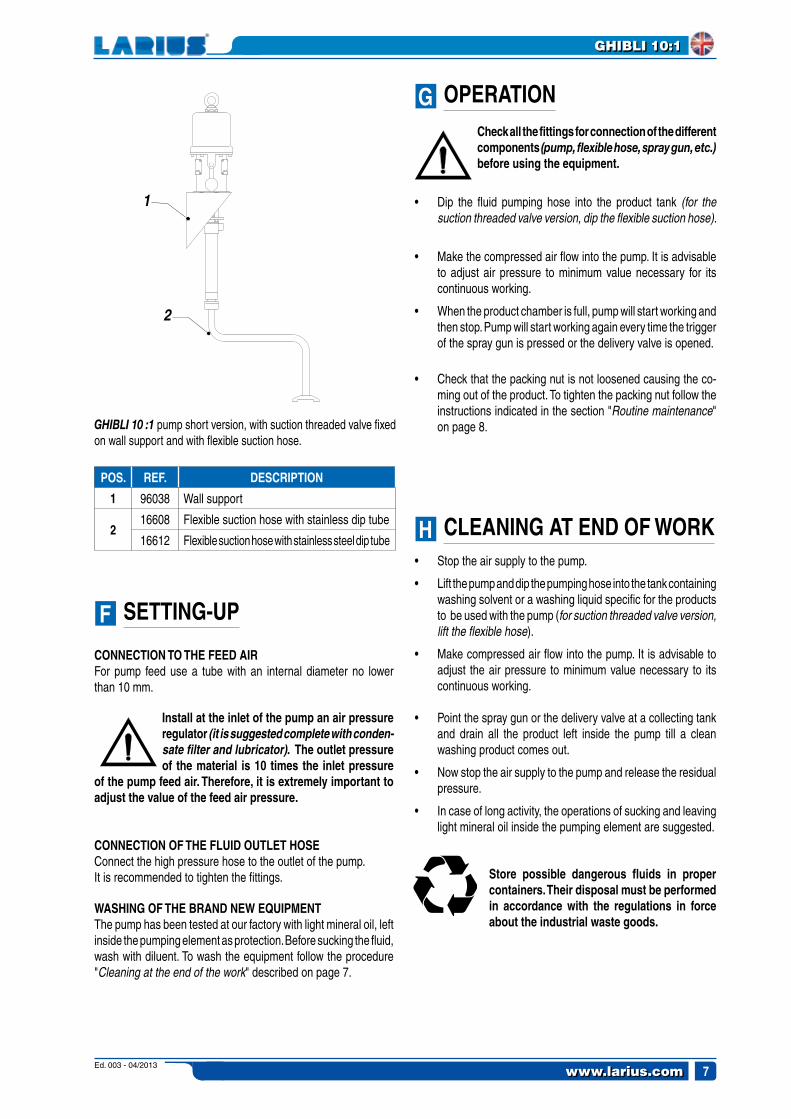
1 96038 Wall support
216608 Flexible suction hose with stainless dip tube
16612 Flexible suction hose with stainless steel dip tube
OPERATION
GHIBLI 10 :1 pump short version, with suction threaded valve fixed on wall support and with flexible suction hose.
Store possible dangerous fluids in proper containers. Their disposal must be performed in accordance with the regulations in force about the industrial waste goods.
CONNECTION TO THE FEED AIRFor pump feed use a tube with an internal diameter no lower than 10 mm.
Install at the inlet of the pump an air pressure regulator (it is suggested complete with conden-sate filter and lubricator). The outlet pressure of the material is 10 times the inlet pressure
of the pump feed air. Therefore, it is extremely important to adjust the value of the feed air pressure.
CONNECTION OF THE FLUID OUTLET HOSEConnect the high pressure hose to the outlet of the pump.It is recommended to tighten the fittings.
WASHING OF THE BRAND NEW EQUIPMENTThe pump has been tested at our factory with light mineral oil, left inside the pumping element as protection. Before sucking the fluid, wash with diluent. To wash the equipment follow the procedure "Cleaning at the end of the work" described on page 7.
SETTING-UP
Check all the fittings for connection of the different components (pump, flexible hose, spray gun, etc.) before using the equipment.
• Dip the fluid pumping hose into the product tank (for the suction threaded valve version, dip the flexible suction hose).
• Make the compressed air flow into the pump. It is advisable to adjust air pressure to minimum value necessary for its continuous working.
• When the product chamber is full, pump will start working and then stop. Pump will start working again every time the trigger of the spray gun is pressed or the delivery valve is opened.
• Check that the packing nut is not loosened causing the co-ming out of the product. To tighten the packing nut follow the instructions indicated in the section "Routine maintenance" on page 8.
• Stop the air supply to the pump.
• Lift the pump and dip the pumping hose into the tank containing washing solvent or a washing liquid specific for the products to be used with the pump (for suction threaded valve version, lift the flexible hose).
• Make compressed air flow into the pump. It is advisable to adjust the air pressure to minimum value necessary to its continuous working.
• Point the spray gun or the delivery valve at a collecting tank and drain all the product left inside the pump till a clean washing product comes out.
• Now stop the air supply to the pump and release the residual pressure.
• In case of long activity, the operations of sucking and leaving light mineral oil inside the pumping element are suggested.
CLEANING AT END OF WORK
Ed. 003 - 04/2013www.larius.com8
GHIBLI 10:1
AI
I1
ROUTINE MAINTENANCE
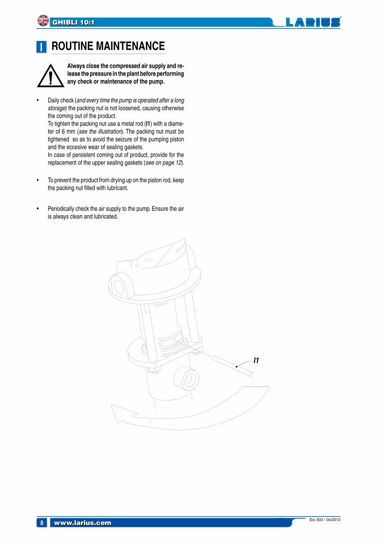
Always close the compressed air supply and re-lease the pressure in the plant before performing any check or maintenance of the pump.
• Daily check (and every time the pump is operated after a long storage) the packing nut is not loosened, causing otherwise the coming out of the product.
To tighten the packing nut use a metal rod (I1) with a diame-ter of 6 mm (see the illustration). The packing nut must be tightened so as to avoid the seizure of the pumping piston and the eccesive wear of sealing gaskets.
In case of persistent coming out of product, provide for the replacement of the upper sealing gaskets (see on page 12).
• To prevent the product from drying up on the piston rod, keep the packing nut filled with lubricant.
• Periodically check the air supply to the pump. Ensure the air is always clean and lubricated.

Ed. 003 - 04/2013 www.larius.com 9
GHIBLI 10:1
L
SolutionPossible causeProblem
• The pump does not start
• Accelerated working and no pres-sure of the pump
• The pump works but the flow of product is not sufficient
• Feed air not sufficient
• Outlet product line clogged
• Inlet product line clogged
• Pneumatic motor blocked at the upper or lower stroke end (Dead Center)
• Crosspiece screws failure of the pneu-matic motor
• Lack of product
• The pumps sucks air
• The product is too fluid
• Gaskets of the pumping rod worn
• The ball of the suction valve does not perfectly "close"
• Air feed pressure is too low
• Gaskets of the pumping rod worn
• Inlet product line clogged
• Product is too thick
• The ball of the suction valve does not perfectly "close"
• Check on the air supply line. Increase the diameter of the feed
hose.
• Clean. Disconnect the outlet hose of the product.
Feed the pump at he minimum pres-sure and verify if the pump starts without the outlet hose.
• Clean the suction pipe.
• Reduce feed pressure;
• Manually reset the pneumatic motor (see on page 10);
• Replace the screws (see on page 10).
• Add product.
• Check the flexible suction hose (only for suction threaded valve ver-
sion).
• Adjust the suction valve (see on page 11).
• Replace the lower gaskets (see on page 12).
• Disassemble the suction valve and clean (see on page 11).
• Increase air pressure.
• Replace the lower gaskets (see on page 12).
• Clean the suction pipe.
• Adjust the suction valve (see on page 11).
• Disassemble the suction valve and clean (see on page 11).
Always close the compressed air supply and release the pressure in the plant before performing any check or replacement of parts of the pump.
TROUBLESHOOTING

Ed. 003 - 04/2013www.larius.com10
GHIBLI 10:1
AM
AN
M1
M2
N1
N2
N4
N3
MANUAL RESET OF THE PNEUMATIC MOTOR
• The feed air pressure of the pump must never be higher than the maximum value indicated in the technical data (see p. 4). Exceed this value can block the valves of the pneumatic motor in the upper or lower position (Dead Center).
• To start again a blocked motor, close the air supply and re-lease pressure in the circuit. This operation should allow the recovery of the valves.
• In case the motor is blocked, proceed as follows:
Close the air supply to the pump and release the residual pressure in the plant.
• Unscrew the eyebolt or handle plug (M1) and pull it upwards together with the guide rod (M2) so allowing the manual release of the stroke reversal group.
• Screw again the plug.
Immediately replace the plug with a usual M8 nut before the guide rod slides into the cylinder (see illustration below).
• Remove the screws (N3).
• Carefully extract the motor cylinder (N4) from the pump.
DISASSEMBLY OF THE PNEU-MATIC MOTOR
Close the compressed air supply to the pump and release the residual pressure in the plant.
• Unscrew the eyebolt or handle plug (N1) and pull it upwards together with the guide rod (N2).
• Hold the guide rod and remove the plug (using two wrenches).
Ed. 003 - 04/2013 www.larius.com 11
GHIBLI 10:1
AO
N5
N6
O2
O1
3,5
mm
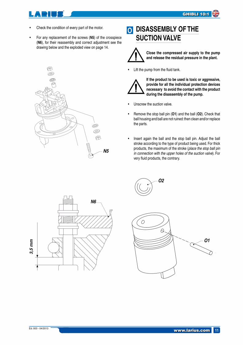
• Check the condition of every part of the motor.
• For any replacement of the screws (N5) of the crosspiece (N6), for their reassembly and correct adjustment see the drawing below and the exploded view on page 14.
DISASSEMBLY OF THE SUCTION VALVE
Close the compressed air supply to the pump and release the residual pressure in the plant.
• Lift the pump from the fluid tank.
If the product to be used is toxic or aggressive, provide for all the individual protection devices necessary to avoid the contact with the product during the disassembly of the pump.
• Unscrew the suction valve.
• Remove the stop ball pin (O1) and the ball (O2). Check that ball housing and ball are not ruined: then clean and/or replace the parts.
• Insert again the ball and the stop ball pin. Adjust the ball stroke according to the type of product being used. For thick products, the maximum of the stroke (place the stop ball pin in connection with the upper holes of the suction valve). For very fluid products, the contrary.

Ed. 003 - 04/2013www.larius.com12
GHIBLI 10:1
AP
AQ
P3
CHECK THE GASKETS: REPLACE IF WORN
P2
P4
P1
• Carefully screw again the fluid cylinder (it is suggested to lay a slight film of vaseline grease on the internal walls of the fluid cylinder).
REPLACEMENT OF THE LOWER GASKETS
Close the compressed air supply to the pump and release the residual pressure in the plant.
• Unscrew and remove the fluid cylinder (P1).
• Hold the bush (P2) with a wrench and with the other wrench unscrew the fitting (P3).
• Exctract the necessary lower gaskets (P4), supplied as spare parts.
• For the reassembling of the gaskets, respect the order as shown in the drawing.
REPLACEMENT OF THE UPPER GASKETS
Close the compressed air supply to the pump and release the residual pressure in the plant.
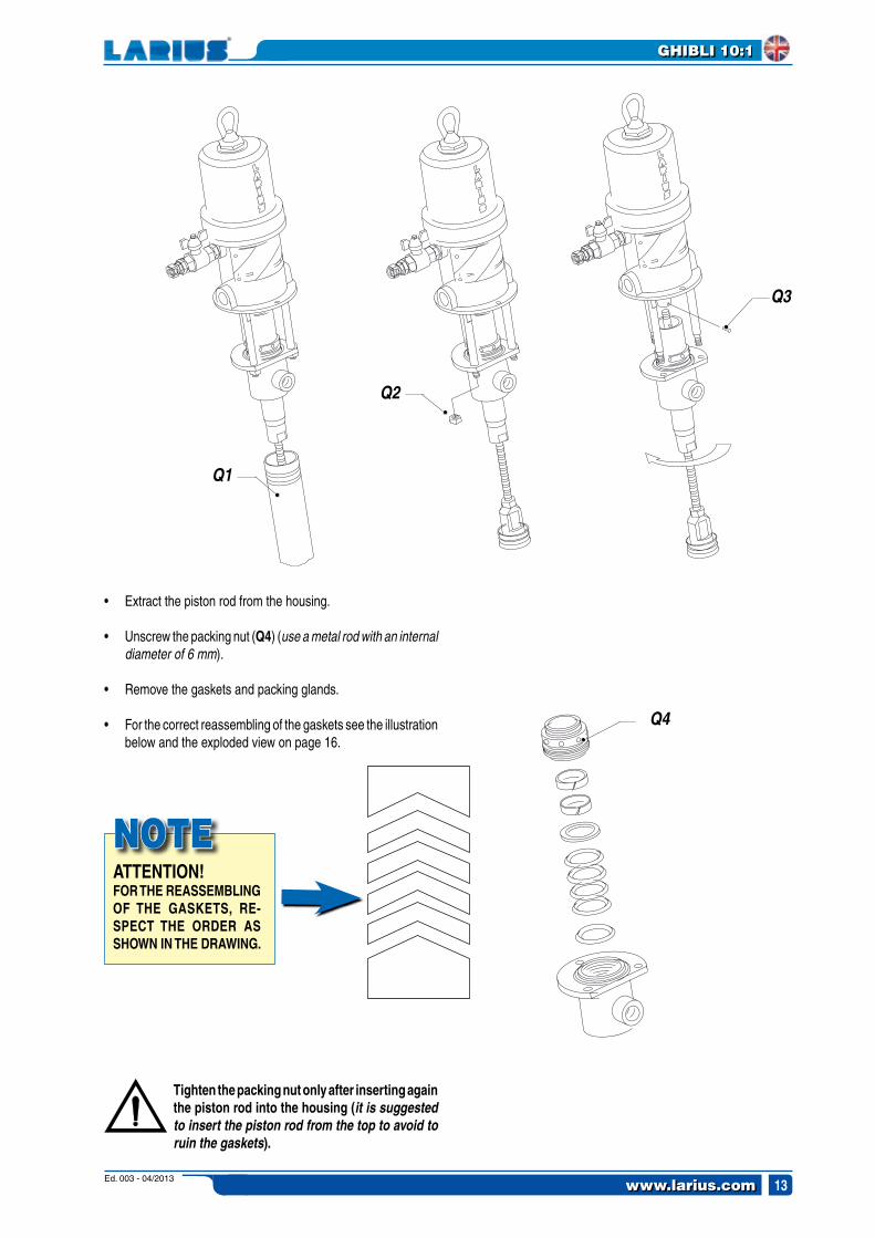
• Unscrew and extract the fluid cyclinder (Q1).
• Unscrew the three nuts (Q2).
• Remove the split pin (Q3) and unscrew the piston rod from the pneumatic motor. Disconnect the pumping group from the pneumatic motor.
Ed. 003 - 04/2013 www.larius.com 13
GHIBLI 10:1
ATTENTION!FOR THE REASSEMBLING OF THE GASKETS, RE-SPECT THE ORDER AS SHOWN IN THE DRAWING.
NOTE
Q4
Q1
Q2
Q3
• Extract the piston rod from the housing.
• Unscrew the packing nut (Q4) (use a metal rod with an internal diameter of 6 mm).
• Remove the gaskets and packing glands.
• For the correct reassembling of the gaskets see the illustration below and the exploded view on page 16.
Tighten the packing nut only after inserting again the piston rod into the housing (it is suggested to insert the piston rod from the top to avoid to ruin the gaskets).

Ed. 003 - 04/2013www.larius.com14
GHIBLI 10:1
1A
12
3
45
67
14
15
16
19
36
3738
39
24
25
26
30
2728
33
35
34
18
179101113
1211
10
8
20
21
22
23
9
40
32
4031
AR COMPLETE PNEUMATIC MOTOR REF. 96669WARNING: always indicate code and quantity for every part required.
Ed. 003 - 04/2013 www.larius.com 15
GHIBLI 10:1
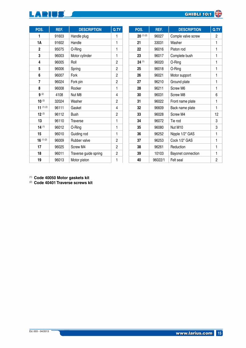
POS. REF. DESCRIPTION Q.TY
1 91603 Handle plug 1
1A 91602 Handle 1
2 95075 O-Ring 1
3 96003 Motor cylinder 1
4 96005 Roll 2
5 96006 Spring 2
6 96007 Fork 2
7 96024 Fork pin 2
8 96008 Rocker 1
9 (2) 4108 Nut M8 4
10 (2) 32024 Washer 2
11 (1) (2) 96111 Gasket 4
12 (2) 96112 Bush 2
13 96110 Traverse 1
14 (1) 96012 O-Ring 1
15 96010 Guiding rod 1
16 (1) (2) 96009 Rubber valve 2
17 96025 Screw M4 2
18 96011 Traverse guide spring 2
19 96013 Motor piston 1
(1) Code 40050 Motor gaskets kit (2) Code 40401 Traverse screws kit
POS. REF. DESCRIPTION Q.TY
20 (1) (2) 96027 Comple valve screw 2
21 33031 Washer 1
22 96016 Piston rod 1
23 96017 Complete bush 1
24 (1) 96020 O-Ring 1
25 96018 O-Ring 1
26 96021 Motor support 1
27 96210 Ground plate 1
28 96211 Screw M6 1
30 96031 Screw M8 6
31 96022 Front name plate 1
32 96609 Back name plate 1
33 96028 Screw M4 12
34 96072 Tie rod 3
35 96080 Nut M10 3
36 96252 Nipple 1/2" GAS 1
37 96253 Cock 1/2" GAS 1
38 96261 Reduction 1
39 10103 Bayonet connection 1
40 96022/1 Felt seal 2
Ed. 003 - 04/2013www.larius.com16
GHIBLI 10:1
27
29
31
30
28
4
3
5
6
7
89
10
11
12
13
14
15
16
19
20
21
22
23
24
25
23
2021
26
17
18
18
3
1
2
32
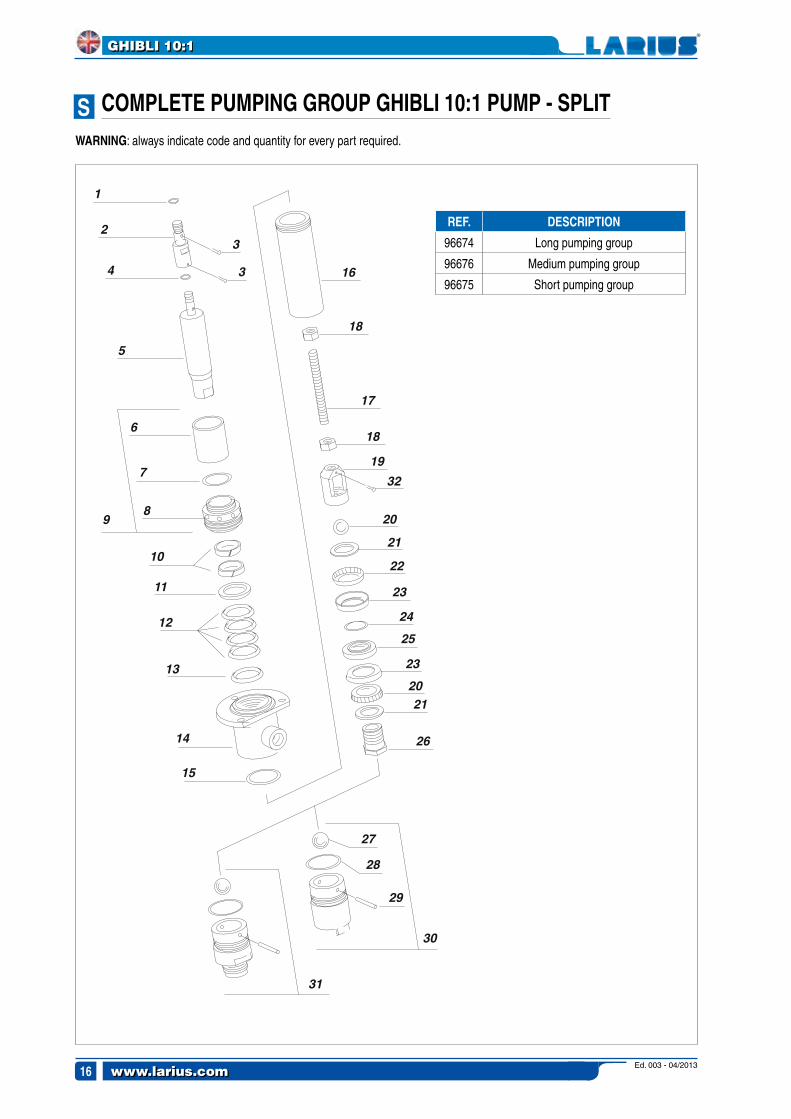
AS COMPLETE PUMPING GROUP GHIBLI 10:1 PUMP - SPLIT
REF. DESCRIPTION
96674 Long pumping group
96676 Medium pumping group
96675 Short pumping group
WARNING: always indicate code and quantity for every part required.

Ed. 003 - 04/2013 www.larius.com 17
GHIBLI 10:1
(1)
(2)
POS. REF. DESCRIPTION Q.TY
1 96073 O-Ring 1
2 96670 Pin 1
3 3323 Split pin 2
4 91008 O-Ring 1
5 98010 Piston rod 1
6 91001/1 Oil tank 1
7 3429 O-Ring 1
8 91371/2 Packing nut 1
9 91371 Complete tank 1
10 (1) (2) 91372 PTFE ring 2
11 98018 Female V ring 1
12 (1) (2) 91375 Gasket 4
13 98011 Male V ring 1
14 91379 Gaskets housing 1
15 91380 O-Ring 1
16
91341 Long fluid cylinder 1
91342 Medium fluid cylinder 1
91346 Short fluid cylinder 1
17
96671 Long tie rod 1
96673 Medium tie rod 1
96672 Short tie rod 1
(1) Code 40236 PTFE gaskets kit(2) Code 40237 Leather gaskets kit
POS. REF. DESCRIPTION Q.TY
18 81010 Nut M12 2
19 91334 Bush 1
20 95021 Ball Ø 7/8" 1
21 98006 Washer 2
22 (2) 91336 Comb spring (x leather gasket) 2
2391384 PTFE gasket (standard) 2
91337 Leather gasket (upon request) 2
24 (1) (2) 91338 O-Ring 1
25 98008 Ring 1
26 98009 Fitting 1
27 95027 Ball Ø 1.1/4" 1
28 (1) (2) 3397 O-Ring 1
29 98023 Stop ball pin 1
30 91385 Complete suction ball 1
31
91392 Compl. M36x2 suction valve 1
96696 Compl. 1" GAS suction valve 1
96695 Compl. 3/4" GAS suction valve 1
32 34005 Split pin (x short version only) 1

Ed. 003 - 04/2013www.larius.com18
GHIBLI 10:1
27
29
31
30
28
4
3
5
6
7
89
10
11
12
13
14
15
16
19
2021
23
2425
23
21
26
17
18
18
1
2
22
3
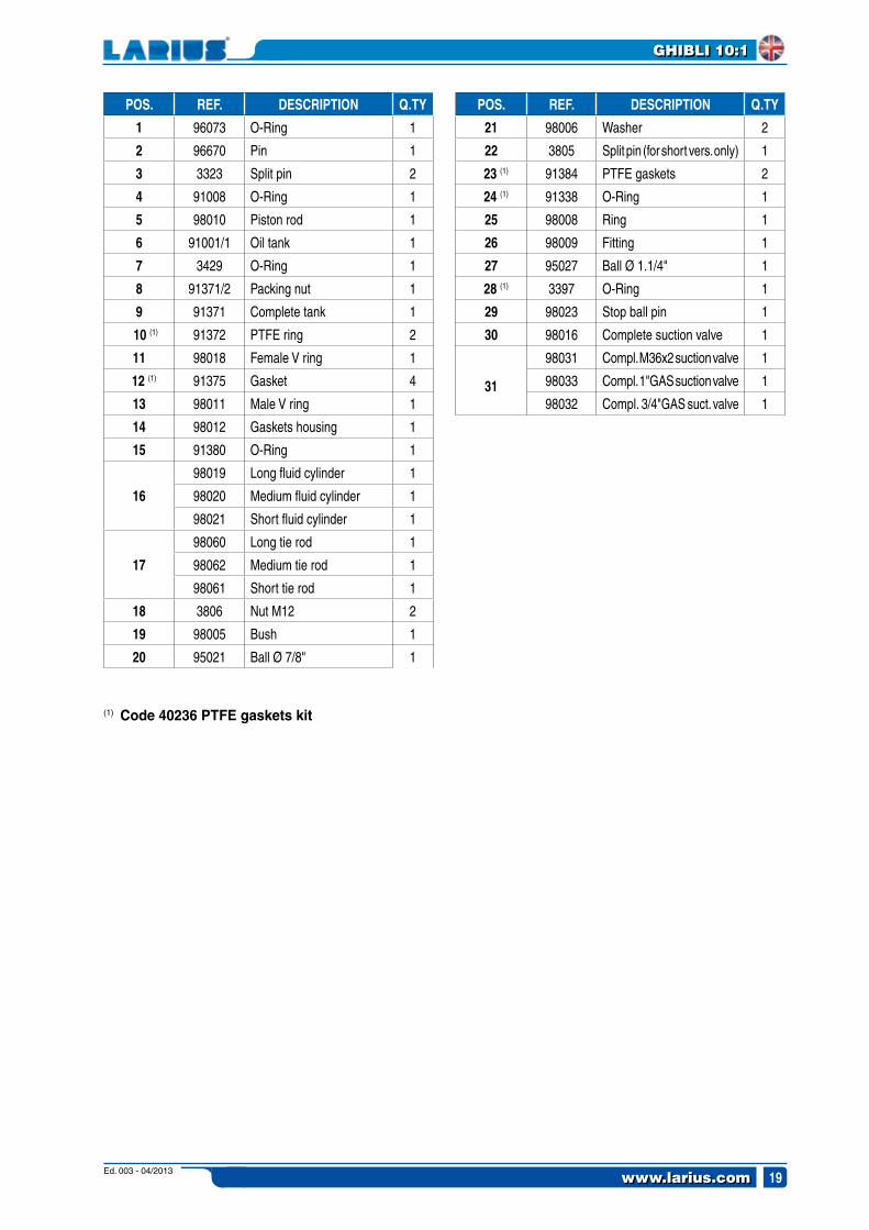
AT COMPLETE PUMPING GROUP GHIBLI 10:1 PUMP - SPLIT ST. STEEL
REF. DESCRIPTION
98050 Long pumping group
98052 Medium pumping group
98051 Short- pumping group
WARNING: always indicate code and quantity for every part required.
Ed. 003 - 04/2013 www.larius.com 19
GHIBLI 10:1
POS. REF. DESCRIPTION Q.TY
1 96073 O-Ring 1
2 96670 Pin 1
3 3323 Split pin 2
4 91008 O-Ring 1
5 98010 Piston rod 1
6 91001/1 Oil tank 1
7 3429 O-Ring 1
8 91371/2 Packing nut 1
9 91371 Complete tank 1
10 (1) 91372 PTFE ring 2
11 98018 Female V ring 1
12 (1) 91375 Gasket 4
13 98011 Male V ring 1
14 98012 Gaskets housing 1
15 91380 O-Ring 1
16
98019 Long fluid cylinder 1
98020 Medium fluid cylinder 1
98021 Short fluid cylinder 1
17
98060 Long tie rod 1
98062 Medium tie rod 1
98061 Short tie rod 1
18 3806 Nut M12 2
19 98005 Bush 1
20 95021 Ball Ø 7/8" 1
(1) Code 40236 PTFE gaskets kit
POS. REF. DESCRIPTION Q.TY
21 98006 Washer 2
22 3805 Split pin (for short vers. only) 1
23 (1) 91384 PTFE gaskets 2
24 (1) 91338 O-Ring 1
25 98008 Ring 1
26 98009 Fitting 1
27 95027 Ball Ø 1.1/4" 1
28 (1) 3397 O-Ring 1
29 98023 Stop ball pin 1
30 98016 Complete suction valve 1
31
98031 Compl. M36x2 suction valve 1
98033 Compl. 1"GAS suction valve 1
98032 Compl. 3/4"GAS suct. valve 1

Ed. 003 - 04/2013www.larius.com20
GHIBLI 10:1
Code 96038: WALL MOUNTING BRACKET
Code 40050 - MOTOR KIT
Code 16608: SUCTION HOSE + THICK PRODUCTS FILTER
Code 16612: ST. STEEL SUCT. HOSE + THICK PRODUCTS FILTER
Code 91107: AIR PRESSURE REGULATOR + CONDENSATION FILTER
Code 40401 - TRAVERSE SCREWS KIT
Code 40236 - PTFE GASKETS KITCode 40237 - LEATHER GASKETS KITCode 40238 - PTFE + LEATHER GASKETS KIT
CODE DESCRIPTION
96660 LONG STANDARD VERSION
96665 MEDIUM STANDARD VERSION
96668 SHORT STANDARD VERSION
CODE DESCRIPTION
96661 LONG STAINLESS STEEL VERSION
96666 MEDIUM STAINLESS STEEL VERSION
96667 SHORT STAINLESS STEEL VERSION
POST RAM complete w/ regulators and compressed air pressure gaugesCode 510500: single-cylinder double-effect post ram for
lt.30 up to max lt.200 drumsCode 510600: single-cylinder double-effect post ram for
lt.30 up to max lt.60 drumsCode 510090: double post ram for max lt.60 drums.
AU ACCESSORIES
AV AVAILABLE VERSIONS

These safety instructions refer to the installation, use and mainte-nance of LARIUS GHIBLI series pneumatic piston transfer pumps in high risk environments where potentially explosive gasses or vapours are present.
These instructions, along with the indica-tions provided in the user and maintenance manual, must be fully respected.
TECHNICAL CHARACTERISTICSThe main characteristics of the GHIBLI series pneumatic piston pumps are provided in the table below
LARIUS GHIBLI SERIES PNEUMATIC PISTON PUMPS ARE GROUP II MECHANICAL DEVI-CES FOR USE IN AREAS WHERE GASSES CLASSIFIED AS IIB (CATEGORY 2 G) ARE PRESENT. THEY ARE DESIGNED AND BUILT IN ACCORDANCE WITH THE 94/9/EC ATEX DIRECTIVE, BASED ON THE FOLLOWING EUROPEAN STANDARDS: EN 1127-1, EN 13463-1ED EN 13463-5.
Maximum number of cycles per minute: 60
Room temperature: -20°C to +60°C
Maximum fluid temperature [°C]: 60°C
ATEX CERTIFICATIONATEX CERTIFICATIONSafety instructions for using GHIBLI series pneumatic piston transfer pumps in high risk environ-ments where potentially explosive gasses or vapours are present.
96700 96710 3:1 3 ÷ 7 bar GC 1/2" Valve Ball GC 1" 21 bar 45 l/min
96701 96755 3:1 3 ÷ 7 bar GC 1/2" Valve Ball GC 1" 21 bar 45 l/min
96705 96715 3:1 3 ÷ 7 bar GC 1/2" Valve Ball GC 1" 21 bar 45 l/min
96660 96661 10:1 3 ÷ 7 bar GC 1/2" Valve Ball GC 3/4" 70 bar 12 l/min
96665 96666 10:1 3 ÷ 7 bar GC 1/2" Valve Ball GC 3/4" 70 bar 12 l/min
96668 96667 10:1 3 ÷ 7 bar GC 1/2" Valve Ball GC 3/4" 70 bar 12 l/min
96870 - 24:1 3 ÷ 7 bar GC 1/2" Piattello GC 3/4" 168 bar 4 l/min
96805 - 24:1 3 ÷ 7 bar GC 1/2" Piattello GC 3/4" 168 bar 4 l/min
96050 96056 30:1 3 ÷ 7 bar GC 3/4" Valve Ball GC 3/8" 210 bar 3,8 l/min
96055 96057 40:1 3 ÷ 7 bar GC 3/4" Valve Ball GC 3/8" 280 bar 3 l/min
Type Rapport Pressure Ø Air inlet Ø Input Ø Output Max working Max
Standard INOX alimetation matetial material pressure flow
DESCRIPTION
Ed. 003 - 04/2013 www.larius.com 21
GHIBLI 10:1
W
X
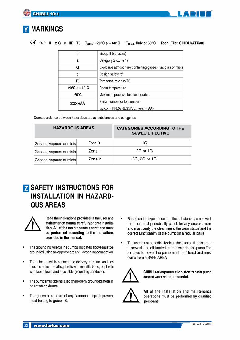
MARKINGS
3
X II 2 G c IIB T6 Tamb: -20°C ÷ + 60°C Tmax. fluido: 60°C Tech. File: GHIBLI/ATX/08
II
2
G
c
T6
- 20°C ÷ + 60°C
60°C
xxxxx/AA
Group II (surfaces)
Category 2 (zone 1)
Explosive atmosphere containing gasses, vapours or mists
Design safety “c”
Temperature class T6
Room temperature
Maximum process fluid temperature
Serial number or lot number
(xxxxx = PROGRESSIVE / year = AA)
Correspondence between hazardous areas, substances and categories
CATEGORIES ACCORDING TO THE 94/9/EC DIRECTIVE
Gasses, vapours or mists
Gasses, vapours or mists
Gasses, vapours or mists
1G
2G or 1G
3G, 2G or 1G
HAZARDOUS AREAS
Zone 0
Zone 1
Zone 2
SAFETY INSTRUCTIONS FOR INSTALLATION IN HAZARD-OUS AREAS
Read the indications provided in the user and maintenance manual carefully prior to installa-tion. All of the maintenance operations must be performed according to the indications provided in the manual.
• The grounding wire for the pumps indicated above must be grounded using an appropriate anti-loosening connection.
• The tubes used to connect the delivery and suction lines must be either metallic, plastic with metallic braid, or plastic with fabric braid and a suitable grounding conductor.
• The pumps must be installed on properly grounded metallic or antistatic drums.
• The gases or vapours of any flammable liquids present must belong to group IIB.
• Based on the type of use and the substances employed, the user must periodically check for any encrustations and must verify the cleanliness, the wear status and the correct functionality of the pump on a regular basis.
• The user must periodically clean the suction filter in order to prevent any solid materials from entering the pump. The air used to power the pump must be filtered and must come from a SAFE AREA.
GHIBLI series pneumatic piston transfer pump cannot work without material.
All of the installation and maintenance operations must be performed by qualified personnel.
Ed. 003 - 04/2013www.larius.com22
GHIBLI 10:1
Z
Y

The diagram shows a typical example of the installation of a pneumatic piston transfer pump.
We Larius S.r.l. Via Stoppani, 21 23801 Calolziocorte (LC)
declare under our sole responsability that the product:
GHIBLI series pneumatic piston transfer pump.
to which this declaration relates complies with the following directives:
- Directive 94/9/EC (ATEX)
3
X
The conformity is under observance of the following standards or standards documents:
- EN 1127-1 - EN 13463-5 - EN 13463-1
Markings
II 2 G c IIB T6 Tamb.: - 20°C ÷ 60°C Tmax. fluido: 60°CTech. File: GHIBLI/ATX/08 Technical dossier kept on file c/o: INERIS (0080)
Calolziocorte- LC Signature (LARIUS)
AB
AA EXAMPLE OF INSTALLATION
Ed. 003 - 04/2013 www.larius.com 23
GHIBLI 10:1
DECLARATIONOF CONFORMITY

www.larius.com
DIRECT LINE
CUSTOMERS TECHNICAL SERVICE
Tel. (39) 0341.621256 - Fax (39) 0341.621234
P A I N T S P R A Y I N G E Q U I P M E N T
MANUFACTURER:
23801 CALOLZIOCORTE - LECCO - ITALY - Via Antonio Stoppani, 21Tel. (39) 0341/62.11.52 - Fax (39) 0341/62.12.43E-mai l : lar ius@lar ius.com - Internet ht tp: / /www.lar ius.com


![An R companion to Experimental Design · PDF file... 1 f +p)"$ + % : "R +p) {s{{n{s{{s{{{s{{n{s{{s{{Xw f{ $p% +67 1'; ( z-:"R % * "$ 3 wp) * ¤] 1 z2?"Rp) + 1 W~X "$ z23' L ...](https://static.fdocuments.us/doc/165x107/5a787ebe7f8b9a852c8b8f29/an-r-companion-to-experimental-design-1-f-p-r-p-snsssnssxw.jpg)


